JP2006142835A - Tape printer - Google Patents
Tape printerDownload PDFInfo
- Publication number
- JP2006142835A JP2006142835AJP2005367557AJP2005367557AJP2006142835AJP 2006142835 AJP2006142835 AJP 2006142835AJP 2005367557 AJP2005367557 AJP 2005367557AJP 2005367557 AJP2005367557 AJP 2005367557AJP 2006142835 AJP2006142835 AJP 2006142835A
- Authority
- JP
- Japan
- Prior art keywords
- tape
- roller
- discharge
- cutting
- cut
- Prior art date
- Legal status (The legal status is an assumption and is not a legal conclusion. Google has not performed a legal analysis and makes no representation as to the accuracy of the status listed.)
- Granted
Links
- 238000005520cutting processMethods0.000claimsabstractdescription73
- 238000007599dischargingMethods0.000claimsabstractdescription23
- 230000005540biological transmissionEffects0.000claimsdescription8
- 230000002093peripheral effectEffects0.000claimsdescription6
- 230000007246mechanismEffects0.000abstractdescription61
- 239000002390adhesive tapeSubstances0.000abstractdescription22
- 230000000903blocking effectEffects0.000abstractdescription2
- 238000003825pressingMethods0.000description20
- 230000007723transport mechanismEffects0.000description5
- 230000000694effectsEffects0.000description4
- 239000004973liquid crystal related substanceSubstances0.000description2
- 239000000853adhesiveSubstances0.000description1
- 230000001070adhesive effectEffects0.000description1
- 238000010438heat treatmentMethods0.000description1
- 238000000034methodMethods0.000description1
- 230000000717retained effectEffects0.000description1
- 238000004804windingMethods0.000description1
Images


Landscapes
- Printers Characterized By Their Purpose (AREA)
- Handling Of Sheets (AREA)
Abstract
Translated fromJapaneseDescription
Translated fromJapanese本発明は、印刷用のテープが収容されるカセットが装着され、当該テープに、予め入力したデータに対応した文字や図形などを印刷し、その印刷したテープを強制的に排出する機構部をもつテーププリンタに関する。 The present invention has a mechanism for loading a cassette for storing a printing tape, printing characters or figures corresponding to previously input data on the tape, and forcibly discharging the printed tape. The present invention relates to a tape printer.
この種のテーププリンタとして、たとえば、特開平8−25756号公報には、印刷用のテープとインクリボンとが収容されたテープカセットが、ケーシング内のカセット収納部に着脱自在に装着され、そのカセット収納部に設けられたサーマルヘッドと、このサーマルヘッドを押圧する揺動可能なプラテンローラとによって、テープカセットから引き出されるテープに予め入力したデータに対応した文字や図形などを印刷するようにしたものが記載されている。そして、この特開平8−25756号公報に記載されるテーププリンタでは、印刷されたテープは、固定刃と可動刃とによって任意の長さにカットされて、ケーシングを矩形状に開口した排出口から切り落とすようにしている。 As this type of tape printer, for example, in Japanese Patent Application Laid-Open No. 8-25756, a tape cassette containing a printing tape and an ink ribbon is detachably mounted in a cassette housing portion in a casing. Characters and figures corresponding to data input in advance on the tape drawn out from the tape cassette are printed by a thermal head provided in the storage section and a swingable platen roller that presses the thermal head. Is described. And in the tape printer described in this Unexamined-Japanese-Patent No. 8-25756, the printed tape is cut to arbitrary lengths with a fixed blade and a movable blade, and it is from the discharge port which opened the casing in the rectangular shape. I'm trying to cut it off.
しかし、テーププリンタによって連続して印刷するような場合には、切り落とされたテープが排出口の付近に次第に溜まっていき、排出口を塞いでしまう場合がある。そのため、一度カットされたテープが下に落ちず、そのまま固定刃と可動刃との間に留まって、再度カットされるなどの不具合を生じることがある。 However, when continuous printing is performed by a tape printer, the tape that has been cut off gradually accumulates in the vicinity of the discharge port and may block the discharge port. For this reason, the tape that has been cut once does not fall down, but remains between the fixed blade and the movable blade as it is, which may cause a problem such as being cut again.
また、このようなテーププリンタは、規格化されたサイズの用紙に印刷するようなものではなく、印刷するデータの多少によって、カットされるテープの長さが適宜決定されるため、たとえば、排出口を塞がないように切り落とされたテープを整列させるための受けトレイを、そのテープの長さに対応させて予め設けておくということもできない。 In addition, such a tape printer is not intended to print on standard-size paper, and the length of the tape to be cut is appropriately determined depending on the amount of data to be printed. It is also impossible to provide a receiving tray for aligning the tapes cut off so as not to block them in advance corresponding to the length of the tape.
本発明は、上記した不具合に鑑みなされたものであり、その目的とするところは、印刷後にカットされたテープによってテープの排出口が塞がれず、良好な連続印刷およびカットを可能とする、テーププリンタを提供することにある。 The present invention has been made in view of the above-described problems, and the object of the present invention is to make it possible to perform good continuous printing and cutting without blocking the outlet of the tape by the tape cut after printing. To provide a printer.
上記の目的を達成するため、請求項1に記載の発明は、テープに印刷するための印刷手段と、印刷されたテープを任意の長さにカットするためのカット手段と、テープを外部へ排出するためのテープ排出口と、テープを搬送するためのテープ搬送手段とを備えるテーププリンタにおいて、前記カット手段によってカットされたテープを前記テープ排出口から強制的に排出するための排出手段を設け、前記排出手段は、前記テープ搬送手段によって前記印刷されたテープが搬送される搬送方向の延長線に沿った位置であって、前記テープ排出口と前記カット手段との間に配設したことを特徴としている。 In order to achieve the above object, the invention described in
また、請求項2に記載の発明は、請求項1に記載のテーププリンタにおいて、前記カット手段がこれを作動するための駆動源を備え、そして前記排出手段は前記駆動源の作動に連動するように構成したことを特徴としている。 According to a second aspect of the present invention, in the tape printer according to the first aspect, the cutting means includes a driving source for operating the cutting means, and the discharging means is interlocked with the operation of the driving source. It is characterized by being configured.
また、請求項3に記載の発明は、請求項1又は2に記載のテーププリンタにおいて、前記排出手段と前記テープ搬送手段を、それぞれ独立した駆動源によって作動するように構成したことを特徴としている。 According to a third aspect of the present invention, in the tape printer according to the first or second aspect, the discharge unit and the tape transport unit are configured to be operated by independent drive sources. .
また、請求項4に記載の発明は、請求項1乃至3の何れかに記載のテーププリンタにおいて、前記カット手段のカット動作に関連してばね力を蓄積するとともに、カット手段のカット動作の解除に関連して蓄積したばね力を解放するばね手段と、 前記ばね手段が解放した前記ばね力を前記排出手段に伝達する伝達手段とを備えて、前記排出手段は、前記伝達手段を介して伝達された前記ばね力に基づいて前記テープの排出を行うように構成されたことを特徴としている。 According to a fourth aspect of the present invention, in the tape printer according to any one of the first to third aspects, the spring force is accumulated in relation to the cutting operation of the cutting means, and the cutting operation of the cutting means is canceled. Spring means for releasing the spring force accumulated in relation to the transmission means, and transmission means for transmitting the spring force released by the spring means to the discharge means, wherein the discharge means is transmitted via the transmission means. The tape is discharged based on the spring force applied.
また、請求項5に記載の発明は、請求項1乃至4の何れかに記載のテーププリンタにおいて、前記排出手段が、テープを排出するための排出ローラを備えていることを特徴としている。 According to a fifth aspect of the present invention, in the tape printer according to any one of the first to fourth aspects, the discharge means includes a discharge roller for discharging the tape.
また、請求項6に記載の発明は、請求項5に記載のテーププリンタにおいて、前記テープ排出口と前記カット手段との間に、前記テープを案内する案内壁を設け、前記案内壁の一部には、前記排出ローラを排出位置に臨ませる切欠部を設けたことを特徴としている。 According to a sixth aspect of the present invention, in the tape printer of the fifth aspect, a guide wall for guiding the tape is provided between the tape discharge port and the cutting means, and a part of the guide wall is provided. Is characterized in that a notch is provided to allow the discharge roller to face the discharge position.
また、請求項7に記載の発明は、請求項5又は6に記載のテーププリンタにおいて、前記排出ローラは、前記駆動源の作動に連動する駆動ローラとその駆動ローラによって作動される従動ローラとからなることを特徴としている。 According to a seventh aspect of the present invention, in the tape printer according to the fifth or sixth aspect, the discharge roller includes a driving roller interlocked with the operation of the driving source and a driven roller operated by the driving roller. It is characterized by becoming.
また、請求項8に記載の発明は、請求項7に記載のテーププリンタにおいて、前記駆動ローラと従動ローラの少なくとも一方の外周部を、ゴム部材で構成したことを特徴としている。 According to an eighth aspect of the present invention, in the tape printer according to the seventh aspect, at least one outer peripheral portion of the driving roller and the driven roller is formed of a rubber member.
以上説明したことから明らかなように、請求項1に記載の発明は、テープに印刷するための印刷手段と、印刷されたテープを任意の長さにカットするためのカット手段と、テープを外部へ排出するためのテープ排出口と、テープを搬送するためのテープ搬送手段とを備えるテーププリンタにおいて、前記カット手段によってカットされたテープを前記テープ排出口から強制的に排出するための排出手段を設け、前記排出手段は、前記テープ搬送手段によって前記印刷されたテープが搬送される搬送方向の延長線に沿った位置であって、前記テープ排出口と前記カット手段との間に配設したものである。 As is apparent from the above description, the invention described in
従って、排出手段がテープ排出口とカット手段の間に配設されて印刷後にカットされたテープがテープ排出口から排出手段によって強制的に排出されるために、カットされたテープによって排出口が塞がれることはなく、連続して印刷とカットを繰り返すような場合でも、良好な印刷およびカット動作を確保することができ、さらに、テープ排出口とカット手段の間であってテープ搬送方向の延長線に沿った位置に排出手段が配設されているため、印刷されたテープが排出口に向かって搬送される過程でテープのカット動作に引き続いて強制排出動作がスムーズに行われるという効果を奏する。 Therefore, since the discharge means is disposed between the tape discharge opening and the cutting means and the tape cut after printing is forcibly discharged from the tape discharge opening by the discharge means, the discharge opening is blocked by the cut tape. Even when printing and cutting are repeated continuously, good printing and cutting operations can be secured, and the tape transport direction is extended between the tape discharge port and the cutting means. Since the discharge means is disposed at a position along the line, the forced discharge operation is smoothly performed following the tape cutting operation in the process in which the printed tape is conveyed toward the discharge port. .
また、請求項2に記載の発明は、請求項1に記載のテーププリンタにおいて、更にカット手段がこれを作動するための駆動源を備え、そして排出手段はこの駆動源の作動に連動するように構成されているため、カット手段のカット動作が行われる駆動源の作動によって排出手段の排出動作もおこなわれるために、テープの排出動作のために特別な駆動源を設ける必要がないというという効果を奏する。 According to a second aspect of the present invention, in the tape printer according to the first aspect, the cutting means further includes a drive source for operating the cut means, and the discharge means is interlocked with the operation of the drive source. Since it is configured, since the discharge operation of the discharge means is also performed by the operation of the drive source in which the cutting operation of the cutting means is performed, there is an effect that it is not necessary to provide a special drive source for the tape discharge operation. Play.
また、請求項3に記載の発明は、請求項1又は2に記載のテーププリンタにおいて、更に排出手段とテープ搬送手段が、それぞれ独立した駆動源によって作動するように構成されているため、テープ排出とテープ搬送とをそれぞれ独立して駆動することができるという効果を奏する。 According to a third aspect of the present invention, in the tape printer according to the first or second aspect, the discharge means and the tape transport means are further configured to operate by independent drive sources. And the tape transport can be driven independently.
また、請求項4に記載の発明は、請求項1乃至3の何れかに記載のテーププリンタにおいて、前記カット手段のカット動作に関連してばね力を蓄積するとともに、カット手段のカット動作の解除に関連して蓄積したばね力を解放するばね手段と、前記ばね手段が解放した前記ばね力を前記排出手段に伝達する伝達手段とを備え、前記排出手段は、前記伝達手段を介して伝達された前記ばね力に基づいて前記テープの排出を行うように構成されたものである。 According to a fourth aspect of the present invention, in the tape printer according to any one of the first to third aspects, the spring force is accumulated in relation to the cutting operation of the cutting means, and the cutting operation of the cutting means is canceled. Spring means for releasing the spring force accumulated in relation to the transmission means, and transmission means for transmitting the spring force released by the spring means to the discharge means. The discharge means is transmitted via the transmission means. Further, the tape is discharged based on the spring force.
従って、排出手段は、カット手段によるカット動作が行われた後に作動するので、テープカット中にテープが引っ張られるような不具合が生じることはなく、さらに、排出手段は、ばね手段に蓄えられ続いてカット動作の解除により一気に解放されるばね力に基づいて、カットされたテープを強制的に排出するのでテープ排出口は塞がれることはなく、連続して印刷とカットを繰り返すような場合でも、良好な印刷およびカット動作を確保することができるという効果を奏する。 Accordingly, since the discharging means operates after the cutting operation by the cutting means is performed, there is no problem that the tape is pulled during the tape cutting, and the discharging means is continuously stored in the spring means. Based on the spring force released at once by the release of the cutting operation, the cut tape is forcibly discharged, so the tape outlet is not blocked, even when printing and cutting are repeated continuously, There is an effect that good printing and cutting operations can be secured.
また、請求項5に記載の発明は、請求項1乃至4の何れかに記載のテーププリンタにおいて、前記排出手段は、テープを排出するための排出ローラを備えているため、その排出ローラによりテープをよりスムーズに排出することができるという効果を奏する。 According to a fifth aspect of the present invention, in the tape printer according to any one of the first to fourth aspects, the discharge means includes a discharge roller for discharging the tape. Can be discharged more smoothly.
また、請求項6に記載の発明は、請求項5に記載のテーププリンタにおいて、前記テープ排出口と前記カット手段との間に、前記テープを案内する案内壁を設け、前記案内壁の一部には、前記排出ローラを排出位置に臨ませる切欠部を設けたものである。 According to a sixth aspect of the present invention, in the tape printer according to the fifth aspect, a guide wall for guiding the tape is provided between the tape discharge port and the cutting means, and a part of the guide wall is provided. Is provided with a notch for allowing the discharge roller to face the discharge position.
従って、テープを案内する案内壁の一部を切り欠き、その切り欠きに排出ローラが臨むように配設されているので、テープ排出口とカット手段の間でテープが排出ローラに確実に導かれるためより確実に案内されて排出ローラによる排出の効果がより高まる。 Therefore, since a part of the guide wall for guiding the tape is cut out and the discharge roller faces the cutout, the tape is surely guided to the discharge roller between the tape discharge port and the cutting means. Therefore, it is guided more reliably and the effect of discharge by the discharge roller is further increased.
また、請求項7に記載の発明は、請求項5又は6に記載のテーププリンタにおいて、排出ローラは、駆動源の作動に連動する駆動ローラとその駆動ローラによって作動される従動ローラとからなるため、双方が回転しながら排出動作を行うためスムーズにテープを排出できるという効果を奏する。 According to a seventh aspect of the present invention, in the tape printer according to the fifth or sixth aspect, the discharge roller is composed of a driving roller interlocked with the operation of the driving source and a driven roller operated by the driving roller. The tape can be discharged smoothly because the discharging operation is performed while both of them rotate.
また、請求項8に記載の発明は、請求項7に記載のテーププリンタにおいて、駆動ローラと従動ローラの少なくとも一方の外周部を、ゴム部材で構成したため、ゴム部材の摩擦力により強制排出をより確実に行うことができるという効果を奏する。 According to an eighth aspect of the present invention, in the tape printer according to the seventh aspect, since at least one outer peripheral portion of the driving roller and the driven roller is made of a rubber member, the forced discharge is further increased by the frictional force of the rubber member. There is an effect that it can be performed reliably.
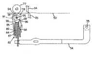
図1は、本発明のテーププリンタの一実施形態の外観を示す斜視図である。このテーププリンタ1は、本体ケーシング2の前部上面に設けられるキーボード3aと、そのキーボード3aの後方の中央部に設けられる液晶ディスプレイ3bと、その液晶ディスプレイ3bの後方に設けられる印刷ユニット4とを備えている。印刷ユニット4内には、後述するテープカセット5を着脱自在に収納するためのカセット収納部6や、次に述べる搬送機構部8、印刷手段としての印刷機構部9およびカット手段としてのカット機構部10などが設けられている。また、カセット収納部6にはテープカセット5を覆うための開閉蓋7が設けられている。さらに、本体ケーシング2における印刷ユニット4の左方には、湾曲状のテープ受け部51が設けられるとともに、本体ケーシング2における印刷ユニット4の左側壁には、矩形状のテープ排出口52が開口されている。 FIG. 1 is a perspective view showing an appearance of an embodiment of a tape printer of the present invention. The
図2は、印刷ユニット4内の要部構成を示す平面図である。図2において、この印刷ユニット4内には、テープカセット5内に収容される印刷用の透明テープ11(後述する。)の搬送やインクリボン13(後述する。)の巻き取りなどを行なうための搬送機構部8、透明テープ11に印刷を行なうための印刷機構部9、および、透明テープ11に印刷がなされ離型紙12(後述する。)が貼り合わされた貼着テープ50(後述する。)をカットするためのカット機構部10が設けられている。 FIG. 2 is a plan view showing a main part configuration in the
搬送機構部8は、カセット収納部6内にそれぞれ独立して起立状に配置される搬送ローラ駆動軸25および巻取ローラ駆動軸26と、カセット収容部6の外側に配置される搬送用モータ27(テープ搬送手段に関わる駆動源)と、カセット収容部6の底壁の下側に設けられるギヤ列28とを備えている。搬送用モータ27からの駆動は、ギヤ列28を介して搬送ローラ駆動軸25および巻取ローラ駆動軸26に伝達され、これによって搬送ローラ駆動軸25および巻取ローラ駆動軸26が回転される。 The
印刷機構部9は、プリンタヘッドとしてのサーマルヘッド29と、プラテンローラ30および可動搬送ローラ31が回転可能に支持されるプラテンホルダ32と、このプラテンホルダ32を、サーマルヘッド29に対して圧接させまたはその圧接を解除するための押圧作動機構部33とを備えている。サーマルヘッド29は、カセット収納部6内において起立状に配置されている。 The
また、プラテンホルダ32は、プラテンローラ30および可動搬送ローラ31を上下方向において平行状に支持するためのローラ支持部34と、このローラ支持部34に支持されるプラテンローラ30および可動搬送ローラ31が、それぞれサーマルヘッド29および固定側搬送ローラ20(後述する。)に対向するように揺動可能に枢支される枢支部35とから構成されている。 The
枢支部35には、その端部に枢着孔が形成されており、この枢着孔をカセットユニット4内において起立状に設けられる枢軸36に支持させて、これによってプラテンホルダ32を枢軸36のまわりに揺動可能に支持させている。また、枢支部35には、その一端が固定されているばね38が係止されており、このばね38の付勢力によって、プラテンホルダ32を、プラテンホルダ32の背面側であって印刷ユニット4内に起立状に設けられる支持板37に当接するようにしている。 A pivot hole is formed at the end of the
ローラ支持部34には、プラテンローラ30を支持するためのプラテンローラ支持部39と可動搬送ローラ31を支持するための可動搬送ローラ支持部40が形成されている。プラテンローラ支持部39は、断面コ字状をなし、その一側においてプラテンローラ30のローラ軸の下側端部を支持するとともに、他側には長溝42を形成して、そのローラ軸の上側端部43をこの長溝42に受け入れるようにしている。また、このプラテンローラ支持部39内には、プラテンローラ30を背面から押圧するばね(図示せず。)が設けられている。これによって、プラテンローラ30がサーマルヘッド29に対して押圧された時にサーマルヘッド29に対してプラテンローラ30が斜め状に当接しても、長溝42に挿通されるローラ軸の上側端部43の移動によって、サーマルヘッド29に対してプラテンローラ30が上下方向において均等な圧力で押圧されるようにしている。さらに、このプラテンローラ支持部39の下端部には、プラテンローラ30のローラ軸41の端部に設けられるギヤ(図示せず。)が回転可能に支持されており、プラテンホルダ32がサーマルヘッド29に対して圧接された時に、このギヤが搬送機構部8のギヤ列28のうちの1つのギヤ41に噛み合い、搬送用モータ27からの駆動がプラテンローラ30に伝達されるように構成している。 The
また、可動搬送ローラ支持部40も同様に、断面コ字状をなし、その一側において可動搬送ローラ31のローラ軸の下側端部を支持するとともに、他側には長溝45を形成して、ローラ軸の上側端部46をこの長溝45に受け入れるようにしている。また、この可動搬送ローラ支持部40内にも、可動搬送ローラ31を背面から押圧するばね(図示せず。)が設けられている。これによって、可動搬送ローラ31が後述するテープカセット5内の搬送ローラ20に対して押圧された時に搬送ローラ20に対して可動搬送ローラ31が斜め状に当接しても、長溝45に挿通されるローラ軸の上側端部46の移動によって、固定側搬送ローラ20に対して可動搬送ローラ31が上下方向において均等な圧力で押圧されるようにしている。さらに、この可動搬送ローラ支持部40の下端部には、可動搬送ローラ31のローラ軸の端部に設けられるギヤ(図示せず。)が回転可能に支持されており、プラテンホルダ32がサーマルヘッド29に対して圧接された時に、このギヤが搬送機構部8のギヤ列28のうちの1つのギヤ44に噛み合い、搬送用モータ27からの駆動が可動搬送ローラ31に伝達されるように構成している。 Similarly, the movable conveyance
押圧作動機構部33は、支持板37において、左右方向にスライド移動可能に設けられるスライド板部材47と、このスライド板部材47に係合し、開閉蓋7の開閉に連動して上下方向に回動されるリリースレバー48と、このリリースレバー48に係合し、水平方向に回動されるカセット当接部材49とを備えている。図3に示すように、テープカセット5がカセット収納部6に装着されると、テープカセット5の前端部がカセット当接部材49に当接して、このカセット当接部材49が枢支軸61を中心として時計方向に回動され、これによって、リリースレバー48が枢支軸53を中心としてやや下向きに回動される。さらに、この状態において、開閉蓋7を閉じると、その開閉蓋7に連動してリリースレバー48が支持軸53を中心としてさらに下向きに回動し、これによって、スライド板部材47がスライド方向左側にスライドして、スライド板部材47の左側端部がプラテンホルダ32の背面を押圧するようになる。その結果、プラテンホルダ32は、ばね38の付勢力に抗して揺動され、プラテンローラ30とサーマルヘッド29とが、互いに押圧される状態となる。 The
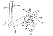
また、図2および図5に示すように、カット機構部10は、固定刃64と、この固定刃64とともにカット動作を行なう可動刃65と、この可動刃65に連結されるリンク機構部72と、このリンク機構部72にギヤ列66を介して連結されるカット用モータ67(カット手段及び排出手段に関わる駆動源)とを備えている。固定刃64は、印刷ユニット4内のカセット収納部6の左側において起立状に設けられる第1側板71に固定されている。可動刃65は、略V字状をなし、そのV字状とされた屈曲部が、この屈曲部を支点として可動刃65が回動できるような状態で第1側板71に支持されている。また、リンク機構部72は、図10にも示すように、ギヤ列66のうちの1つのギヤに噛み合うリンクギヤ73と、そのリンクギヤ73から突出し、V字状とされた可動刃64の一方の側に形成される長孔63に挿入されるリンク軸74と、そのリンクギヤ73から反対側に突出するカム75とを備えている。そして、カット用モータ67の駆動により、ギヤ列66を介してリンクギヤ73が回転されると、リンク軸74に連結された可動刃65が、その屈曲部を支点として揺動することによって、貼着テープ50をカットするようにしている。 As shown in FIGS. 2 and 5, the
図4は、カセット収納部6に収納されるテープカセット5内の要部構成を示す平面図である。次に、このように構成された印刷ユニット4のカセット収納部6に収納されるテープカセット5について説明する。図4において、このテープカセット5内には、透明テープリール14が右側後部において回転可能に設けられており、その透明テープリール14に隣り合う左側後部には、離型紙リール15が回転可能に設けられている。また、透明テープリール14と離型紙リール15との間の中央部には筒状の巻取ローラ17が回転可能に設けられるとともに、その巻取ローラ17に隣り合う斜め右側前方にはインクリボンリール16が回転可能に設けられている。また、このテープカセット5の前部には、サーマルヘッド29が嵌め込まれる嵌合部18が形成されており、この嵌合部18の一部が前方に向かって開口されることによって印刷処理部19が形成されている。さらに、嵌合部18に隣り合う左側前部には、筒状の搬送ローラ20が回転可能に設けられている。 FIG. 4 is a plan view showing the main configuration of the
このテープカセット5には、印刷用の透明テープ11、離型紙12およびインクリボン13の3種のテープが、それぞれ、透明テープリール14、離型紙リール15およびインクリボンリール16に巻回された状態で収容されている。透明テープ11は、透明テープリール14から、右側前部に設けられたころ21および22を介して印刷処理部19に引き出される。また、インクリボン13は、インクリボンリール16から印刷処理部19に引き出され、その後、ころ23を介して巻取ローラ17によって巻き取られる。また、離型紙12は、離型紙リール15から、ころ24と搬送ローラ20との間に引き出される。 In this
そして、このように構成されたテープカセット5は、カセット収納部6にセットされることによって、巻取ローラ17に巻取ローラ駆動軸26が嵌め込まれるとともに、搬送ローラ20に搬送ローラ駆動軸25が嵌め込まれ、搬送用モータ27の駆動に従って巻取ローラ17および搬送ローラ20が回転駆動され、これによって印刷用の透明テープ11の搬送やインクリボン13の巻き取りが行なわれる。そして、透明テープ11が、印刷処理部19において、インクリボン13と密着するような状態でサーマルヘッド29とプラテン30との間に挟まれて、サーマルヘッド29の発熱素子によって予め入力したデータに応じた文字や図形などの印刷がなされ、次いで、離型紙12を貼り合わせて貼着テープ50とした後に、上記したカット機構部10において、そのデータが印刷された長さに応じた任意の長さにカットされる。 The
このようなテーププリンタ1において、本実施形態では、図2に示すように、本体ケーシング2に開口されるテープ排出口51の近傍に配設され、カット機構部10においてカットされた後の貼着テープ50をテープ排出口52から強制的に排出するための排出手段として機能する排出機構部76を設けている。 In such a
この排出機構部76は、図2および図6に示すように、固定ローラ77と、この固定ローラ77に対して貼着テープ50を挟んで対向する排出ローラとしての可動ローラ78と、この可動ローラ78を貼着テープ50に対して押圧し、またはその押圧を解除するように作動される押圧作動手段としての押圧作動機構部79と、この押圧作動機構部79の押圧解除動作に連動して、可動ローラ78を貼着テープ50を排出するように回転させるための強制送出手段としての強制送出機構部80とを備えている。尚、前記排出手段の主体である固定ローラ77と可動ローラ78は、共同して粘着テープ50を排出する状態において、図2、図9、図11、図13及び図15に示されるように粘着テープ50の搬送方向の延長線に沿って設けられている。 2 and 6, the
テープ排出口52の内側には、図6に示すように、貼着シート50の排出を案内するための2つの案内壁81および82が設けられている。この2つの案内壁81および82は、固定刃64と可動刃65とでカットされた貼着テープ50の排出位置において、互いに所定の間隔が隔てられるように配置されている。そして、この2つの案内壁81および82の上下方向途中部が切り欠かれ、一方の案内壁81には、固定ローラ77が、この切欠部から貼着テープ50の排出位置に臨むようにして設けられている。一方、他方の案内壁82には、可動ローラ78が、この切欠部から貼着テープ50の排出位置に臨むようにして、強制送出機構部80を構成するローラホルダ83に支持されている。 As shown in FIG. 6, two
このローラホルダ83は、図7ないし図9に示すように、ローラホルダ本体84と、可動ローラ78を回転自在に支持するローラ支持部材85と、可動ローラ78を押圧するローラ押圧部材86と、2つの付勢ばね87および88とによって構成されている。一方、可動ローラ78は、図8に示すように、ローラ本体90と、このローラ本体90に形成される外周溝92に嵌め込まれるリング状のローラゴム91とにより構成されている。ローラ本体90における外周溝92の下側には、図9に示すように、2つの段部93が互いに180°変位した位置に設けられる第1突出部94と、その第1突出部94の下側に設けられる略断面矩形状の第2突出部95とが形成されている。 7 to 9, the
ローラ支持部材85は、この可動ローラ78をその上下方向から挟み込むようにして回転自在に支持するとともに、その軸部89に付勢ばね87が挿入された状態でローラホルダ本体84に取り付けられている。また、ローラ押圧部材86も付勢ばね88が介在された状態でローラホルダ本体84に取り付けられ、常には、その先端が可動ローラ78の第1突出部94の段部93を押圧している。また、ロールホルダ本体84には、固定ローラ77に向かう方向へ移動可能であり、その先端が可動ローラ78に向かって折曲げられたフック部材99が設けられており、図9に示すように、待機状態においては、フック部材99の先端が可動ローラ78の第2突出部95の側面に当接している。また、ロールホルダ本体84の下部には、2つの長孔96および97が、横に並ぶような状態で形成されるとともに、その上端部には2つの係止部材98が設けられている。ここで、ローラ支持部材85、ローラ押圧部材86、軸部89、段部93、第1突出部94、第2突出部95は伝達手段に相当し、さらに付勢ばね87、付勢ばね88は、ばね手段に相当する。 The
また、図2に示すように、印刷ユニット4内の第1側板71よりもさらに左方には、第2側板68が起立状に設けられており、図5に示すように、ロールホルダ83は、この第2側板68に横に並んで設けられる2つのピン69および70に、ロールホルダ本体84に形成される2つの長孔96および97を挿入させることによって、固定ローラ77に対して可動ローラ78が近接または離反する方向にスライド可能に支持されている。 Further, as shown in FIG. 2, a
また、ロールホルダ本体84の上端部に設けられる2つの係止部材98の間には、揺動アーム54の一端が摺動可能に取り付けられている。この揺動アーム54の他端部は、印刷ユニット4の底壁から起立する枢支軸55に取り付けられている。また、その途中部位には係止孔56が設けられており、この係止孔56には、揺動アーム54の揺動動作と可動刃65の揺動動作とを連動させるためのリンクアーム57の一端が挿入されている。このリンクアーム57は、図10にも示すように、略J字状をなし、リンクギヤ73に設けられるカム75に嵌め込まれるとともに、その下端部が係止軸58によって回動可能に支持されている。 In addition, one end of the
そして、カット用モータ67の駆動によって、リンクギヤ73が回転されると、リンクアーム57は、カム75の外周面に沿って係止軸58を支点として揺動され、その揺動に従って揺動アーム54が揺動される。さらに、この揺動アーム54の揺動に従ってロールホルダ83がスライドされ、これによって、可動ローラ78が固定ローラ77に対して近接または離反する方向にスライドされる。このように、押圧作動機構部79は、カム75、リンクアーム57、揺動アーム54およびロールホルダ83などによって構成されている。 When the
次に、このように構成されたカット機構部10および排出機構部76によって、貼着テープ50がカットされた後にテープ排出口52から強制的に排出される機構について、図9ないし図20を参照して説明する。 Next, with reference to FIGS. 9 to 20, a mechanism for forcibly ejecting the
図9および図10では、貼着テープ50のカットを待っている待機状態が示されている。この待機状態においては、図10に示すように、固定刃64と可動刃65とは最も開いた状態で保持されており、また、これに従って、可動ローラ78は固定ローラ77から最も離れた位置で保持されている。そして、ローラ押圧部材86が可動ローラ78の第1突出部94の一方の段部93を付勢ばね88の作用により押圧して、可動ローラ78を反時計方向に回転させようとするが、フック部材99の先端端面が可動ローラ78の第2突出部95の側面と当接しているので、可動ローラ78の反時計方向への回転が妨げられ、可動ローラ78は停止している。 In FIG. 9 and FIG. 10, a standby state waiting for cutting of the
次に、この待機状態からカット用モータ67の駆動によってカット動作が開始されると、可動刃65が、リンクギヤ73の回転によってリンク軸74を介して固定刃64に近接する方向に揺動される。また、それとともに、リンクギヤ73の回転によってリンクアーム57を介して揺動アーム54が揺動され、これによってローラホルダ83がスライドされ、可動ローラ78が固定ローラ77に押圧される。この状態が図11および図12に示されている。図11および図12に示すように、本実施形態では、貼着テープ50がカットされる前に、まず可動ローラ78が貼着テープ50を挟むような状態で固定ローラ77に押圧される。そして、この可動ローラ78と固定ローラ77とで貼着テープ50を挟んだ状態で貼着テープ50がカットされた状態が、図13および図14に示されている。この状態では、図13に示すように、固定ローラ77に対して可動ローラ78が押圧されることにより、ローラ支持部材85がローラホルダ本体84側に押しつけられ、これによってローラ支持部材85の軸部89に挿入される付勢ばね87には付勢力が蓄えられる状態となる。また、これとともに、ローラ押圧部材86の先端部は、ローラ本体90に形成される第1突出部94の段部93に、付勢ばね88の付勢力によって強く押圧された状態となる。フック部材99は、カット動作に伴って固定ローラ77に向かって移動するが、その先端端面は依然として第2突出部95の側面に当接しているので、可動ローラ78の反時計方向への回転が妨げられ、可動ローラ78は停止したままである。 Next, when the cutting operation is started by driving the cutting
そして、貼着テープ50のカットが終了すると、図15および図16に示すように、フック部材99と第2突出部95との当接が外れることにより、ローラ押圧部材86の付勢ばね88の付勢が解除されるので、そのローラ押圧部材86が付勢ばね88のばね力によって、第1突出部94の段部93を押してローラ本体90を貼着シート50を排出する方向に回転させ、これによって貼着シート50がそのローラ本体90が回転した分だけ排出される。また、このローラ本体90の回転によって、第2突出部95がフック部材99の折曲部分に引っ掛かることが可能な状態となる。続いて、固定刃64に対して可動刃65が離れるように動作されると、これに連動して、可動ローラ78は、固定ローラ77に対する押圧が解除されるように動作される。この状態が図17および図18に示されている。図17および図18に示されるように、可動ローラ78が固定ローラ77に対してその押圧が解除されるように動作されると、ローラ支持部材85の軸部89に挿入される付勢ばね87の付勢力が解放され始めるので、可動ローラ78に対してローラホルダ83が離れるように動作され、これによって、フック部材99が固定ローラ77から離れる方向に移動し、その折曲部分が第2突出部95に係合するようになる。 When the cutting of the
そして、固定刃64に対して可動刃65がさらに離れるように動作されると、これに連動して、可動ローラ78は、固定ローラ77に対して、さらにその押圧が解除されるように動作される。この状態が図19および図20に示されている。この図19および図20に示されるように、可動ローラ78の固定ローラ77に対する押圧力がある一定以上に解除されると、ローラ支持部材85の軸部89に挿入される付勢ばね87の付勢力が一気に解放されて、可動ローラ78は固定ローラ77との当接状態が保持されたまま、フック部材99が勢いよく固定ローラ77から離れる方向に移動する。この移動により、フック部材99の折曲部分が第2突出部95の一端を引っ掛けて、第2突出部95を反時計方向に回転させる。これによってローラ本体90が、貼着シート50を排出する方向に勢いよく回転され、貼着シート50が強制的に排出される。このような貼着シート50の排出が終了すると、可動刃65および可動ローラ78は、再び図9および図10に示す待機状態まで揺動される。 When the
このような構成によれば、貼着テープ50がテープ排出口52から排出機構部76の強制的な排出動作によって排出されるので、カットされた貼着テープ50によってテープ排出口52が塞がれることはなく、連続して印刷しカットするような場合でも、良好な印刷およびカット動作を確保することができる。 According to such a configuration, the
また、本実施形態では、排出機構部76排出動作と、カット機構部10のカット動作を、リンク機構部72、リンクアーム57および揺動アーム54によって連動させているので、カットされる貼着テープ50の長さがその都度変更されても、カットされた貼着テープ50をその度毎に確実に排出させることができる。 Moreover, in this embodiment, since the
さらに、本実施形態の排出機構部76では、カット終了後に、まずローラ押圧部材86の押圧力によってロール本体90を回転させ、次いで可動ローラ78の固定ローラ77に対する押圧力がある一定以上解除された時に、ローラ支持部材85の軸部89に挿入される付勢ばね87の付勢を一気に解放して、ローラ本体90を、貼着シート50を排出する方向に勢いよく回転させ、貼着シート50を強制的に排出させるようにしているので、簡易な構成によって確実な排出動作を確保できる。また、このような段階的な排出によって、貼着テープ50を確実に排出させることができる。 Further, in the
なお、以上述べた実施形態では、テーププリンタ1の構成要素として、排出機構部76を設けたが、たとえば、このような排出機構部76を構成する、固定ローラ77、可動ローラ78、押圧作動機構部79および強制送出機構部80によってシートを排出するためのシート排出装置を構成して、たとえば、シートにスタンプを押すスタンプ装置に、このシート排出装置を適用してもよい。 In the above-described embodiment, the
1 テーププリンタ
5 テープカセット
9 印刷機構部
10 カット機構部
33 押圧作動機構部
50 貼着テープ
52 テープ排出口
76 排出機構部
79 押圧作動機構部
80 強制送出機構部
DESCRIPTION OF
Claims (8)
Translated fromJapanese前記カット手段によってカットされたテープを前記テープ排出口から強制的に排出するための排出手段を設け、
前記排出手段は、前記テープ搬送手段によって前記印刷されたテープが搬送される搬送方向の延長線に沿った位置であって、前記テープ排出口と前記カット手段との間に配設したことを特徴とするテーププリンタ。Printing means for printing on a tape, cutting means for cutting the printed tape into an arbitrary length, a tape discharge port for discharging the tape to the outside, and a tape conveying means for conveying the tape A tape printer comprising:
A discharge means for forcibly discharging the tape cut by the cutting means from the tape discharge port;
The discharge means is a position along an extended line in the transport direction in which the printed tape is transported by the tape transport means, and is disposed between the tape discharge port and the cut means. And a tape printer.
前記ばね手段が解放した前記ばね力を前記排出手段に伝達する伝達手段とを備え、
前記排出手段は、前記伝達手段を介して伝達された前記ばね力に基づいて前記テープの排出を行うように構成されたことを特徴とする請求項1乃至3の何れかに記載のテーププリンタ。A spring means for accumulating a spring force related to the cutting operation of the cutting means, and a spring means for releasing the accumulated spring force related to the release of the cutting operation of the cutting means;
Transmission means for transmitting the spring force released by the spring means to the discharge means,
4. The tape printer according to claim 1, wherein the discharging unit is configured to discharge the tape based on the spring force transmitted through the transmitting unit.
8. The tape printer according to claim 7, wherein an outer peripheral portion of at least one of the driving roller and the driven roller is made of a rubber member.
Priority Applications (1)
| Application Number | Priority Date | Filing Date | Title |
|---|---|---|---|
| JP2005367557AJP4289349B2 (en) | 2005-12-21 | 2005-12-21 | Tape printer |
Applications Claiming Priority (1)
| Application Number | Priority Date | Filing Date | Title |
|---|---|---|---|
| JP2005367557AJP4289349B2 (en) | 2005-12-21 | 2005-12-21 | Tape printer |
Related Parent Applications (1)
| Application Number | Title | Priority Date | Filing Date |
|---|---|---|---|
| JP24295898ADivisionJP3852215B2 (en) | 1998-08-28 | 1998-08-28 | Tape printer |
Related Child Applications (1)
| Application Number | Title | Priority Date | Filing Date |
|---|---|---|---|
| JP2008150207ADivisionJP4337938B2 (en) | 2008-06-09 | 2008-06-09 | Tape printer |
Publications (2)
| Publication Number | Publication Date |
|---|---|
| JP2006142835Atrue JP2006142835A (en) | 2006-06-08 |
| JP4289349B2 JP4289349B2 (en) | 2009-07-01 |
Family
ID=36623038
Family Applications (1)
| Application Number | Title | Priority Date | Filing Date |
|---|---|---|---|
| JP2005367557AExpired - Fee RelatedJP4289349B2 (en) | 2005-12-21 | 2005-12-21 | Tape printer |
Country Status (1)
| Country | Link |
|---|---|
| JP (1) | JP4289349B2 (en) |
Cited By (17)
| Publication number | Priority date | Publication date | Assignee | Title |
|---|---|---|---|---|
| CN101934647A (en)* | 2009-06-30 | 2011-01-05 | 兄弟工业株式会社 | Tape box |
| WO2011074086A1 (en)* | 2009-12-16 | 2011-06-23 | ブラザー工業株式会社 | Tape cassette |
| US8061915B2 (en)* | 2007-06-04 | 2011-11-22 | Seiko Epson Corporation | Tape processing apparatus |
| US8360667B2 (en) | 2009-06-10 | 2013-01-29 | Brother Kogyo Kabushiki Kaisha | Printer |
| US8384750B2 (en) | 2010-03-31 | 2013-02-26 | Brother Kogyo Kabushiki Kaisha | Printing apparatus |
| US8382389B2 (en) | 2008-12-25 | 2013-02-26 | Brother Kogyo Kabushiki Kaisha | Tape cassette |
| US8562228B2 (en) | 2008-12-25 | 2013-10-22 | Brother Kogyo Kabushiki Kaisha | Tape printer |
| US8564632B2 (en) | 2010-03-31 | 2013-10-22 | Brother Kogyo Kabushiki Kaisha | Thermal printer |
| US8740482B2 (en) | 2009-03-31 | 2014-06-03 | Brother Kogyo Kabushiki Kaisha | Tape printer |
| US8757907B2 (en) | 2009-03-31 | 2014-06-24 | Brother Kogyo Kabushiki Kaisha | Tape cassette |
| US8764326B2 (en) | 2009-03-31 | 2014-07-01 | Brother Kogyo Kabushiki Kaisha | Tape cassette |
| US9132682B2 (en) | 2009-03-31 | 2015-09-15 | Brother Kogyo Kabushiki Kaisha | Tape unit and tape cassette |
| US9174476B2 (en) | 2010-02-26 | 2015-11-03 | Brother Kogyo Kabushiki Kaisha | Ribbon guide in a tape cassette |
| US9566808B2 (en) | 2009-03-31 | 2017-02-14 | Brother Kogyo Kabushiki Kaisha | Tape cassette |
| US9656495B2 (en) | 2009-12-28 | 2017-05-23 | Brother Kogyo Kabushiki Kaisha | Tape cassette |
| KR20220059797A (en)* | 2020-11-03 | 2022-05-10 | 송유빈 | Portable braille printer |
| US12296580B2 (en) | 2009-03-31 | 2025-05-13 | Brother Kogyo Kabushiki Kaisha | Tape cassette |
- 2005
- 2005-12-21JPJP2005367557Apatent/JP4289349B2/ennot_activeExpired - Fee Related
Cited By (85)
| Publication number | Priority date | Publication date | Assignee | Title |
|---|---|---|---|---|
| US8061915B2 (en)* | 2007-06-04 | 2011-11-22 | Seiko Epson Corporation | Tape processing apparatus |
| US9682584B2 (en) | 2008-12-25 | 2017-06-20 | Brother Kogyo Kabushiki Kaisha | Tape cassette |
| US9511610B2 (en) | 2008-12-25 | 2016-12-06 | Brother Kogyo Kabushiki Kaisha | Tape cassette |
| US12233641B2 (en) | 2008-12-25 | 2025-02-25 | Brother Kogyo Kabushiki Kaisha | Tape cassette |
| US11479053B2 (en) | 2008-12-25 | 2022-10-25 | Brother Kogyo Kabushiki Kaisha | Tape cassette |
| US11285749B2 (en) | 2008-12-25 | 2022-03-29 | Brother Kogyo Kabushiki Kaisha | Tape cassette |
| US8382389B2 (en) | 2008-12-25 | 2013-02-26 | Brother Kogyo Kabushiki Kaisha | Tape cassette |
| US10744798B2 (en) | 2008-12-25 | 2020-08-18 | Brother Kogyo Kabushiki Kaisha | Tape cassette |
| US10661589B2 (en) | 2008-12-25 | 2020-05-26 | Brother Kogyo Kabushiki Kaisha | Tape cassette |
| US8562228B2 (en) | 2008-12-25 | 2013-10-22 | Brother Kogyo Kabushiki Kaisha | Tape printer |
| US10189284B2 (en) | 2008-12-25 | 2019-01-29 | Brother Kogyo Kabushiki Kaisha | Tape cassette |
| US9855779B2 (en) | 2008-12-25 | 2018-01-02 | Brother Kogyo Kabushiki Kaisha | Tape cassette |
| US9656497B2 (en) | 2008-12-25 | 2017-05-23 | Brother Kogyo Kabushiki Kaisha | Tape cassette |
| US12304229B2 (en) | 2008-12-25 | 2025-05-20 | Brother Kogyo Kabushiki Kaisha | Tape cassette |
| US9751349B2 (en) | 2008-12-25 | 2017-09-05 | Brother Kogyo Kabushiki Kaisha | Tape cassette |
| US8651756B2 (en) | 2008-12-25 | 2014-02-18 | Brother Kogyo Kabushiki Kaisha | Tape cassette |
| US9656496B2 (en) | 2008-12-25 | 2017-05-23 | Brother Kogyo Kabushiki Kaisha | Tape cassette |
| US9649861B2 (en) | 2008-12-25 | 2017-05-16 | Brother Kogyo Kabushiki Kaisha | Tape cassette |
| US8770877B2 (en) | 2008-12-25 | 2014-07-08 | Brother Kogyo Kabushiki Kaisha | Tape printer |
| US9566812B2 (en) | 2008-12-25 | 2017-02-14 | Brother Kogyo Kabushiki Kaisha | Tape cassette |
| US9539838B2 (en) | 2008-12-25 | 2017-01-10 | Brother Kogyo Kabushiki Kaisha | Tape Cassette |
| US9533522B2 (en) | 2008-12-25 | 2017-01-03 | Brother Kogyo Kabushiki Kaisha | Tape cassette |
| US9522556B2 (en) | 2008-12-25 | 2016-12-20 | Brother Kogyo Kabushiki Kaisha | Tape cassette |
| US9511611B2 (en) | 2008-12-25 | 2016-12-06 | Brother Kogyo Kabushiki Kaisha | Tape cassette |
| US9511609B2 (en) | 2008-12-25 | 2016-12-06 | Brother Kogyo Kabushiki Kaisha | Tape cassette |
| US9493016B2 (en) | 2008-12-25 | 2016-11-15 | Brother Kogyo Kabushiki Kaisha | Tape cassette |
| US9498998B2 (en) | 2008-12-25 | 2016-11-22 | Brother Kogyo Kabushiki Kaisha | Tape cassette |
| US9498997B2 (en) | 2008-12-25 | 2016-11-22 | Brother Kogyo Kabushiki Kaisha | Tape cassette |
| US9132682B2 (en) | 2009-03-31 | 2015-09-15 | Brother Kogyo Kabushiki Kaisha | Tape unit and tape cassette |
| US9566808B2 (en) | 2009-03-31 | 2017-02-14 | Brother Kogyo Kabushiki Kaisha | Tape cassette |
| US9409425B2 (en) | 2009-03-31 | 2016-08-09 | Brother Kogyo Kabushiki Kaisha | Tape cassette |
| US9498987B2 (en) | 2009-03-31 | 2016-11-22 | Brother Kogyo Kabushiki Kaisha | Tape cassette |
| US9403389B2 (en) | 2009-03-31 | 2016-08-02 | Brother Kogyo Kabushiki Kaisha | Tape cassette |
| US9381756B2 (en) | 2009-03-31 | 2016-07-05 | Brother Kogyo Kabushiki Kaisha | Tape cassette |
| US9498988B2 (en) | 2009-03-31 | 2016-11-22 | Brother Kogyo Kabushiki Kaisha | Tape cassette |
| US9370949B2 (en) | 2009-03-31 | 2016-06-21 | Brother Kogyo Kabushiki Kaisha | Tape cassette |
| US12296580B2 (en) | 2009-03-31 | 2025-05-13 | Brother Kogyo Kabushiki Kaisha | Tape cassette |
| US9346296B2 (en) | 2009-03-31 | 2016-05-24 | Brother Kogyo Kabushiki Kaisha | Tape cassette |
| US12257827B2 (en) | 2009-03-31 | 2025-03-25 | Brother Kogyo Kabushiki Kaisha | Tape cassette |
| US11945217B2 (en) | 2009-03-31 | 2024-04-02 | Brother Kogyo Kabushiki Kaisha | Tape cassette |
| US11707938B2 (en) | 2009-03-31 | 2023-07-25 | Brother Kogyo Kabushiki Kaisha | Tape cassette |
| US9011028B2 (en) | 2009-03-31 | 2015-04-21 | Brother Kogyo Kabushiki Kaisha | Tape cassette |
| US10201993B2 (en) | 2009-03-31 | 2019-02-12 | Brother Kogyo Kabushiki Kaisha | Tape cassette |
| US10201988B2 (en) | 2009-03-31 | 2019-02-12 | Brother Kogyo Kabushiki Kaisha | Tape cassette |
| US11254149B2 (en) | 2009-03-31 | 2022-02-22 | Brother Kogyo Kabushiki Kaisha | Tape cassette |
| US9592692B2 (en) | 2009-03-31 | 2017-03-14 | Brother Kogyo Kabushiki Kaisha | Tape cassette |
| US9616690B2 (en) | 2009-03-31 | 2017-04-11 | Brother Kogyo Kabushiki Kaisha | Tape cassette |
| US8764326B2 (en) | 2009-03-31 | 2014-07-01 | Brother Kogyo Kabushiki Kaisha | Tape cassette |
| US8764325B2 (en) | 2009-03-31 | 2014-07-01 | Brother Kogyo Kabushiki Kaisha | Tape cassette |
| US8757907B2 (en) | 2009-03-31 | 2014-06-24 | Brother Kogyo Kabushiki Kaisha | Tape cassette |
| US11052685B2 (en) | 2009-03-31 | 2021-07-06 | Brother Kogyo Kabushiki Kaisha | Tape cassette |
| US9656488B2 (en) | 2009-03-31 | 2017-05-23 | Brother Kogyo Kabushiki Kaisha | Tape cassette |
| US10744802B2 (en) | 2009-03-31 | 2020-08-18 | Brother Kogyo Kabushiki Kaisha | Tape cassette |
| US10675894B2 (en) | 2009-03-31 | 2020-06-09 | Brother Kogyo Kabushiki Kaisha | Tape cassette |
| US8740482B2 (en) | 2009-03-31 | 2014-06-03 | Brother Kogyo Kabushiki Kaisha | Tape printer |
| US10618325B2 (en) | 2009-03-31 | 2020-04-14 | Brother Kogyo Kabushiki Kaisha | Tape cassette |
| US9427988B2 (en) | 2009-03-31 | 2016-08-30 | Brother Kogyo Kabushiki Kaisha | Tape cassette |
| US10226949B2 (en) | 2009-03-31 | 2019-03-12 | Brother Kogyo Kabushiki Kaisha | Tape cassette |
| US8360667B2 (en) | 2009-06-10 | 2013-01-29 | Brother Kogyo Kabushiki Kaisha | Printer |
| US8641304B2 (en) | 2009-06-30 | 2014-02-04 | Brother Kogyo Kabushiki Kaisha | Tape cassette |
| CN101934647A (en)* | 2009-06-30 | 2011-01-05 | 兄弟工业株式会社 | Tape box |
| US12194765B2 (en) | 2009-06-30 | 2025-01-14 | Brother Kogyo Kabushiki Kaisha | Tape cassette |
| US9573401B2 (en) | 2009-06-30 | 2017-02-21 | Brother Kogyo Kabushiki Kaisha | Tape cassette |
| US9802432B2 (en) | 2009-06-30 | 2017-10-31 | Brother Kogyo Kabushiki Kaisha | Tape cassette |
| US11225099B2 (en) | 2009-06-30 | 2022-01-18 | Brother Kogyo Kabushiki Kaisha | Tape cassette |
| US9676217B2 (en) | 2009-06-30 | 2017-06-13 | Brother Kogyo Kabushiki Kaisha | Tape cassette |
| EP2845743A1 (en)* | 2009-12-16 | 2015-03-11 | Brother Kogyo Kabushiki Kaisha | Tape cassette |
| CN102510806B (en)* | 2009-12-16 | 2014-06-18 | 兄弟工业株式会社 | with box |
| EP2514600A4 (en)* | 2009-12-16 | 2013-05-08 | Brother Ind Ltd | BAND CASSETTE |
| CN102510806A (en)* | 2009-12-16 | 2012-06-20 | 兄弟工业株式会社 | with box |
| JP5212550B2 (en)* | 2009-12-16 | 2013-06-19 | ブラザー工業株式会社 | Tape cassette |
| US11235600B2 (en) | 2009-12-16 | 2022-02-01 | Brother Kogyo Kabushiki Kaisha | Tape cassette |
| US10265976B2 (en) | 2009-12-16 | 2019-04-23 | Brother Kogyo Kabushiki Kaisha | Tape cassette |
| WO2011074086A1 (en)* | 2009-12-16 | 2011-06-23 | ブラザー工業株式会社 | Tape cassette |
| US9352600B2 (en) | 2009-12-16 | 2016-05-31 | Brother Kogyo Kabushiki Kaisha | Tape cassette |
| US9539837B2 (en) | 2009-12-16 | 2017-01-10 | Brother Kogyo Kabushiki Kaisha | Tape cassette |
| US11135862B2 (en) | 2009-12-28 | 2021-10-05 | Brother Kogyo Kabushiki Kaisha | Tape cassette with indicator portion having pressing and non-pressing portion for indentifying tape type |
| US9656495B2 (en) | 2009-12-28 | 2017-05-23 | Brother Kogyo Kabushiki Kaisha | Tape cassette |
| US12128697B2 (en) | 2009-12-28 | 2024-10-29 | Brother Kogyo Kabushiki Kaisha | Tape cassette |
| US10265982B2 (en) | 2009-12-28 | 2019-04-23 | Brother Kogyo Kabushiki Kaisha | Tape cassette |
| US9174476B2 (en) | 2010-02-26 | 2015-11-03 | Brother Kogyo Kabushiki Kaisha | Ribbon guide in a tape cassette |
| US8564632B2 (en) | 2010-03-31 | 2013-10-22 | Brother Kogyo Kabushiki Kaisha | Thermal printer |
| US8384750B2 (en) | 2010-03-31 | 2013-02-26 | Brother Kogyo Kabushiki Kaisha | Printing apparatus |
| KR102444223B1 (en) | 2020-11-03 | 2022-09-16 | 송유빈 | Portable braille printer |
| KR20220059797A (en)* | 2020-11-03 | 2022-05-10 | 송유빈 | Portable braille printer |
Also Published As
| Publication number | Publication date |
|---|---|
| JP4289349B2 (en) | 2009-07-01 |
Similar Documents
| Publication | Publication Date | Title |
|---|---|---|
| JP4289349B2 (en) | Tape printer | |
| JP5432050B2 (en) | Portable printer | |
| CN106132715B (en) | with box | |
| US20110058884A1 (en) | Tape cassette | |
| JP3721745B2 (en) | Recording device | |
| EP1950049B1 (en) | Continuous sheet processing apparatus and method of setting a roll body in the continuous sheet processing apparatus | |
| JP3852215B2 (en) | Tape printer | |
| CN107405937B (en) | with box | |
| CN101318415A (en) | with processing unit | |
| CN106103116B (en) | with box | |
| JP4337938B2 (en) | Tape printer | |
| CN102120388B (en) | Recording device | |
| CN106103112B (en) | With printing device and with printing system | |
| JP5289881B2 (en) | Tape printer | |
| JP4983888B2 (en) | Label printer | |
| JP7346940B2 (en) | Cutting device and printing device | |
| JP4033073B2 (en) | Tape printer | |
| JP3705002B2 (en) | Tape cartridge and tape printer having the same | |
| JP3724414B2 (en) | Printer device | |
| JP4900357B2 (en) | Printing device | |
| JP3899690B2 (en) | Tape printer | |
| JP3356015B2 (en) | Tape printer | |
| JP3780613B2 (en) | Web roll storage cassette | |
| JP3385926B2 (en) | Tape feeder and tape printer having the same | |
| JPH10139224A (en) | Recorder |
Legal Events
| Date | Code | Title | Description |
|---|---|---|---|
| A131 | Notification of reasons for refusal | Free format text:JAPANESE INTERMEDIATE CODE: A131 Effective date:20080826 | |
| RD02 | Notification of acceptance of power of attorney | Free format text:JAPANESE INTERMEDIATE CODE: A7422 Effective date:20081017 | |
| A521 | Written amendment | Free format text:JAPANESE INTERMEDIATE CODE: A523 Effective date:20081024 | |
| A131 | Notification of reasons for refusal | Free format text:JAPANESE INTERMEDIATE CODE: A131 Effective date:20081125 | |
| A521 | Written amendment | Free format text:JAPANESE INTERMEDIATE CODE: A523 Effective date:20090123 | |
| TRDD | Decision of grant or rejection written | ||
| A01 | Written decision to grant a patent or to grant a registration (utility model) | Free format text:JAPANESE INTERMEDIATE CODE: A01 Effective date:20090310 | |
| A01 | Written decision to grant a patent or to grant a registration (utility model) | Free format text:JAPANESE INTERMEDIATE CODE: A01 | |
| A61 | First payment of annual fees (during grant procedure) | Free format text:JAPANESE INTERMEDIATE CODE: A61 Effective date:20090323 | |
| R150 | Certificate of patent or registration of utility model | Free format text:JAPANESE INTERMEDIATE CODE: R150 | |
| FPAY | Renewal fee payment (event date is renewal date of database) | Free format text:PAYMENT UNTIL: 20120410 Year of fee payment:3 | |
| FPAY | Renewal fee payment (event date is renewal date of database) | Free format text:PAYMENT UNTIL: 20120410 Year of fee payment:3 | |
| FPAY | Renewal fee payment (event date is renewal date of database) | Free format text:PAYMENT UNTIL: 20130410 Year of fee payment:4 | |
| FPAY | Renewal fee payment (event date is renewal date of database) | Free format text:PAYMENT UNTIL: 20130410 Year of fee payment:4 | |
| FPAY | Renewal fee payment (event date is renewal date of database) | Free format text:PAYMENT UNTIL: 20140410 Year of fee payment:5 | |
| LAPS | Cancellation because of no payment of annual fees |