JP2006130691A - Method and apparatus for dividing and cutting fragile material - Google Patents
Method and apparatus for dividing and cutting fragile materialDownload PDFInfo
- Publication number
- JP2006130691A JP2006130691AJP2004319510AJP2004319510AJP2006130691AJP 2006130691 AJP2006130691 AJP 2006130691AJP 2004319510 AJP2004319510 AJP 2004319510AJP 2004319510 AJP2004319510 AJP 2004319510AJP 2006130691 AJP2006130691 AJP 2006130691A
- Authority
- JP
- Japan
- Prior art keywords
- brittle material
- condensing
- laser beam
- line
- cleaving
- Prior art date
- Legal status (The legal status is an assumption and is not a legal conclusion. Google has not performed a legal analysis and makes no representation as to the accuracy of the status listed.)
- Granted
Links
- 239000000463materialSubstances0.000titleclaimsabstractdescription106
- 238000000034methodMethods0.000titleclaimsdescription12
- 230000003287optical effectEffects0.000claimsdescription15
- 230000001678irradiating effectEffects0.000claimsdescription5
- 238000011144upstream manufacturingMethods0.000claimsdescription4
- 238000010521absorption reactionMethods0.000description5
- 239000011521glassSubstances0.000description3
- 230000003028elevating effectEffects0.000description2
- 239000004973liquid crystal related substanceSubstances0.000description2
- 239000004065semiconductorSubstances0.000description2
- 239000000758substrateSubstances0.000description2
- 238000004519manufacturing processMethods0.000description1
- 238000012986modificationMethods0.000description1
- 230000004048modificationEffects0.000description1
- 238000002407reformingMethods0.000description1
Images


Landscapes
- Dicing (AREA)
- Processing Of Stones Or Stones Resemblance Materials (AREA)
- Laser Beam Processing (AREA)
Abstract
Description
Translated fromJapanese本発明は脆性材料の割断方法とその装置に関し、脆性材料にレーザ光を照射して所要の形状に割断するようにした割断方法とその装置に関する。 The present invention relates to a brittle material cleaving method and apparatus, and more particularly to a cleaving method and apparatus for irradiating a brittle material with a laser beam to cleave it into a required shape.
従来、ガラスや半導体材料などの板状の脆性材料を所要の割断予定線に従って割断するため、レーザ光を集光して上記脆性材料に照射し、該レーザ光を上記割断予定線に沿って移動させる方法が知られている。(特許文献1〜3)
これらの特許文献では、上記脆性材料の内部に、レーザ光を集光させて集光点を形成し、この集光点の部分で多光子吸収を発生させることで、その部分をクラック領域や溶融処理領域などの改質領域に変質させる。
そして上記集光点を割断予定線に沿って移動させることで、上記改質領域が割断予定線に沿って形成され、その後、脆性材料に人為的な力を印加したり、またはそのまま放置することで、上記改質領域を基点に脆性材料の表面までクラックが進展し、脆性材料を割断予定線で分離させることができる。
特に特許文献3の割断方法では、上記集光点を板厚方向に順次移動させ、上記改質領域を脆性材料のレーザ光の入射方向に複数形成する割断方法であって、当該方法により板厚の厚い脆性材料であっても割断可能となっている。
In these patent documents, a laser beam is condensed inside the brittle material to form a condensing point, and multiphoton absorption is generated at the condensing point portion, so that the portion is cracked or melted. Change to a modified region such as a processing region.
Then, by moving the condensing point along the planned cutting line, the modified region is formed along the planned cutting line, and then an artificial force is applied to the brittle material or left as it is. Thus, cracks propagate to the surface of the brittle material with the modified region as a base point, and the brittle material can be separated along the planned cutting line.
In particular, the cleaving method of
上記特許文献1、2の場合、板厚の厚い脆性材料を割断するには、改質領域を形成した後、大きな力を脆性材料に印加させるか、レーザ光の出力を上げて集光点を中心に広範囲な改質領域を形成させ、当該改質領域を板厚方向に拡大させる必要がある。
しかしながら、大きな力を脆性材料に印加する際、改質領域と脆性材料の表面までの距離が離れていると、改質領域からのクラックが割断予定線に沿って進展せず、精度良く割断できないという問題がある。
また広範囲に改質領域を形成してしまうと、改質領域は脆性材料の厚さ方向だけではなく、割断予定線の幅方向にも拡大してしまうため、改質領域の幅内で割断した面がゆがみ、精度良く割断できないという問題がある。
さらに、上記特許文献3の場合、改質領域を脆性材料の板厚方向に複数形成するため、割断予定線の同じ位置に、改質領域を板厚方向に複数形成しなければならず、割断に時間がかかってしまう。
このような問題を解決するため、本発明は板厚の厚い脆性材料であっても、高精度でかつ短時間に割断することの可能な脆性材料の割断方法及びその装置を提供するものである。In the case of the above-mentioned
However, when a large force is applied to the brittle material, if the distance between the modified region and the surface of the brittle material is large, cracks from the modified region do not propagate along the planned cutting line and cannot be cleaved accurately. There is a problem.
If a modified region is formed over a wide area, the modified region expands not only in the thickness direction of the brittle material but also in the width direction of the planned cutting line. There is a problem that the surface is distorted and cannot be cleaved with high accuracy.
Furthermore, in the case of the above-mentioned
In order to solve such problems, the present invention provides a brittle material cleaving method and apparatus capable of cleaving in a short time with high accuracy even for a brittle material having a large plate thickness. .
すなわち、本発明に係る脆性材料の割断方法は、レーザ光を集光して板状の脆性材料に照射し、当該レーザ光を脆性材料の割断予定線に沿って移動させて、上記脆性材料の割断を行う脆性材料の割断方法において、
上記レーザ光をその光軸方向に線状に集光させて集光線を形成するとともに、該レーザ光を、上記集光線が脆性材料の内部に形成されるように脆性材料に照射して脆性材料の割断を行うことを特徴としている。That is, the brittle material cleaving method according to the present invention condenses the laser beam and irradiates the plate-like brittle material, moves the laser beam along the planned fracture line of the brittle material, In the cleaving method of brittle material for cleaving,
The laser beam is condensed linearly in the optical axis direction to form a condensed line, and the brittle material is irradiated with the laser beam so that the condensed line is formed inside the brittle material. It is characterized by cleaving.
また、本発明に係る脆性材料の割断装置は、レーザ光を発振するレーザ発振器と、レーザ発振器からのレーザ光を集光する集光手段と、上記集光手段と脆性材料とを相対移動させる移動手段とを備え、集光手段により集光されたレーザ光を、移動手段によって板状の脆性材料の割断予定線に沿って移動させ、上記脆性材料の割断を行う脆性材料の割断装置において、
上記集光手段を、上記レーザ光をその光軸方向に線状に集光させて集光線を形成する集光手段から構成して、上記集光線が脆性材料の内部に形成されるようにレーザ光を脆性材料に照射させて脆性材料の割断を行うことを特徴としている。The brittle material cleaving apparatus according to the present invention includes a laser oscillator that oscillates laser light, a condensing means that condenses the laser light from the laser oscillator, and a movement that relatively moves the condensing means and the brittle material. A brittle material cleaving apparatus for cleaving the brittle material by moving the laser light collected by the light converging means along the planned fracture line of the plate-shaped brittle material by the moving means.
The condensing means is composed of condensing means for condensing the laser beam in the optical axis direction to form a condensing line, so that the condensing line is formed inside the brittle material. The brittle material is cleaved by irradiating the brittle material with light.
上記割断方法及びその装置によれば、レーザ光を光軸方向に線状に集光させて集光線とし、さらにこの集光線を脆性材料の内部に形成されるようにしているので、脆性材料の内部に板厚方向に改質領域が形成することができる。
このため、板厚の厚い脆性材料であっても、形成された改質領域から脆性材料の表面までの距離を接近させることができるので、クラックが進展しやすく、また割断予定線の幅方向に改質領域が広がらないので、割断予定線に沿って高精度に割断を行うことができる。
さらに、上記集光線を移動手段によって割断予定線に沿って移動させればよいので、改質領域を板厚方向に複数形成する必要がなく、短時間に割断を行うことができる。According to the cleaving method and the apparatus, the laser beam is condensed in a linear shape in the optical axis direction to form a condensing line, and this condensing line is formed inside the brittle material. A modified region can be formed inside in the thickness direction.
For this reason, even with a brittle material with a large plate thickness, the distance from the formed modified region to the surface of the brittle material can be made closer, so that cracks tend to progress and the width of the planned breaking line is increased. Since the reforming region does not widen, the cutting can be performed with high accuracy along the planned cutting line.
Furthermore, since it is sufficient to move the condensing line along the planned cutting line by the moving means, it is not necessary to form a plurality of modified regions in the plate thickness direction, and the cutting can be performed in a short time.
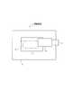
以下図示実施例について説明すると、図1は本発明に係る割断装置1を示し、この割断装置1により、透明な液晶ガラス基板等の脆性材料2を割断予定線Qに沿って割断するようになっている。
この割断装置1は、板状の脆性材料2を支持する加工テーブル3と、この加工テーブル3の上方に配置されて該加工テーブル3上の脆性材料2に対してレーザ光Lを照射する照射手段4と、この照射手段4を加工テーブル3上の脆性材料2に対して相対移動させる移動手段5とを備えている。
上記脆性材料2として、上述した液晶ガラス基板の他、半導体用のウェハなどの板状の脆性材料2を割断できるようになっており、本実施例の割断装置1によれば、上記脆性材料2の板厚が1000μmを越えていても、高精度で短時間に割断することが可能となっている。
加工テーブル3は工場内等の所定位置に固定されており、脆性材料2を下面から吸着保持して、脆性材料2が加工テーブル3上でずれないようになっている。FIG. 1 shows a cleaving apparatus 1 according to the present invention, and this cleaving apparatus 1 cleaves a
The cleaving apparatus 1 includes a processing table 3 that supports a plate-like
As the
The processing table 3 is fixed at a predetermined position in a factory or the like, and the
次に、図2に示すように、照射手段4は移動手段5に固定されたハウジング11と、当該ハウジング11内に配置されてレーザ光Lを発振するレーザ発振器12と、レーザ光Lを集光する集光手段13とを備えている。
上記移動手段5は、ハウジング11と共に、上記レーザ発振器12および集光手段13を平面方向及び垂直方向に移動させるようになっている。なお、上記移動手段5は従来公知であるため、詳細な説明は省略する。
上記レーザ発振器12は、短パルスUVレーザ光を発振し、本実施例では波長を紫外領域とし、パルス幅10ナノ秒以下、繰り返し周波数10kHz以上、平均出力2W以上の範囲で調節したレーザ光Lを発振するようになっている。
そして上記集光手段13はレーザ発振器12から発振されたレーザ光Lの光軸上に設けられており、本実施例の集光手段13は3枚の第1〜第3アキシコンレンズ14A〜14Cと、1枚の凸レンズ15とから構成されている。
またこれらのレンズはそれぞれ図示しない昇降手段によって相互に上下方向に移動可能となっており、レーザ光Lの集光を調節するようになっている。Next, as shown in FIG. 2, the irradiating means 4 includes a
The moving means 5 moves the
The
The condensing means 13 is provided on the optical axis of the laser beam L oscillated from the
Each of these lenses can be moved in the vertical direction by an elevating means (not shown), and the condensing of the laser light L is adjusted.
ここで、図3を用いてアキシコンレンズ14について説明すると、本実施例のアキシコンレンズ14は、少なくとも一方の面が略円錐状に加工されたレンズのことをいい、本実施例のアキシコンレンズ14は他方の面が平坦に加工されている。
図3に示すように、レーザ発振器12から照射されるレーザ光Lの光軸と、アキシコンレンズ14の中心とを一致させ、その状態でレーザ光Lをアキシコンレンズ14の円錐状の面に照射すると、レーザ光Lは円錐状の面でアキシコンレンズ14の中心に向けて屈折する。
屈折したレーザ光Lはアキシコンレンズ14の中心で集光され、集光による光強度の強い部分は、レーザ光Lの光軸方向に延びて線状の集光線Cとなり、この集光線Cの光軸方向の長さを焦点深度Dという。
そしてこの集光線Cの部分におけるレーザ光Lの光強度を脆性材料2の吸収閾値以上とすれば、この集光線Cの位置で脆性材料2が多光子吸収により変質し、当該部分に改質領域Tが形成され、集光線C以外の光強度が吸収閾値以下の部分は非改質領域となり、改質領域と非改質領域の境界がクラックとなる。
ただ、図3のようにアキシコンレンズ14の内部に上記集光線Cが形成されてしまうと、アキシコンレンズ14内に光強度の高い部分が位置してしまうので、アキシコンレンズ14自体が変質してしまうおそれがある。Here, the
As shown in FIG. 3, the optical axis of the laser beam L emitted from the
The refracted laser light L is collected at the center of the
If the light intensity of the laser beam L in the portion of the condensing line C is set to be equal to or higher than the absorption threshold of the
However, if the condensing line C is formed inside the
そこで、本実施例の集光手段4ではレーザ光Lの光路の上流側に、相互に円錐状の面が向き合うように配置した略同形状の第1,第2アキシコンレンズ14A,14Bを配置することで、各レンズの内部に集光線Cが形成されないようにしている。
すなわち、第1,第2アキシコンレンズ14A,14Bの円錐状の面が向き合うように配置することで、第1アキシコンレンズ14Aで屈折したレーザ光Lは、リング状に拡散し、その後拡散したレーザ光Lは第2アキシコンレンズ14Bで屈折して略円筒状のレーザ光Lとなる。
そして、この略円筒状のレーザ光Lは、円錐状の面を第2アキシコンレンズ14Bに向けた第3アキシコンレンズ14Cと、凸面を光路の上流側に向けた凸レンズ15とによって集光され、上記集光線Cが形成される。
このように、一旦第1,第2アキシコンレンズ14A,14Bによってレーザ光を拡散させてから再び第3アキシコンレンズ14C及び凸レンズ15によって集光することで、上記各レンズ内に集光線形成されるのを防止している。
なお、上記凸レンズ15を省略しても、レーザ光Lを集光して集光線Cを形成することが可能であることは言うまでもない。Therefore, in the light condensing means 4 of the present embodiment, the first and
That is, by arranging the conical surfaces of the first and
The substantially cylindrical laser light L is condensed by a third axicon lens 14C having a conical surface directed toward the
In this way, once the laser light is diffused by the first and
Needless to say, even if the
このようにして形成される集光線Cの焦点深度Dは、レーザ発振器12によるレーザ光Lの径や、上記昇降手段による各レンズの間隔によって適宜調整され、さらに上記移動手段5によってハウジング11の位置が調整されるようになっている。
本実施例では、集光線Cの位置を脆性材料2の略中央とし、焦点深度Dは脆性材料2の板厚の半分以上であって、集光線Cの両端と脆性材料の表面までの距離が等しくなるようにしている。なお、この集光線Cの両端と脆性材料の表面までの距離は、脆性材料の種類や板厚によって適宜変更可能となっている。
そして移動手段5は照射手段4を脆性材料2に対して相対移動させて、上記集光線Cを割断予定線Qに沿って移動させ、これにより、集光線Cの通過する位置で多光子吸収が発生し、割断予定線Qに沿って改質領域Tが形成される。
その結果、脆性材料2によっては、脆性材料2に力を印加しなくとも、改質領域Tと脆性材料2の表面との距離が近いので、上記改質領域Tの両端よりクラックが成長して脆性材料2の表面に達し、脆性材料2が割断予定線Qに沿って割断される。
また、クラックが脆性材料2の表面に達しなくとも、少しの力を脆性材料2に印加すれば、脆性材料2を割断予定線Qに沿って割断することができる。The focal depth D of the condensing line C formed in this way is adjusted as appropriate according to the diameter of the laser beam L by the
In the present embodiment, the position of the condensing line C is set to the approximate center of the
Then, the moving means 5 moves the irradiation means 4 relative to the
As a result, depending on the
Even if the crack does not reach the surface of the
このように、本実施例によれば、上記集光手段13によってレーザ光Lを板厚方向に伸びる線状の集光線Cに集光すると共に、この集光線Cの焦点深度Dを板厚の半分以上とすることで、これを割断予定線Qに沿って移動させるだけで、自然に、若しくは少ない力で脆性材料2を割断予定線Qに沿って割断することができる。
このとき、改質領域Tから脆性材料2の表面までの距離が近いので、クラックはほとんど割断予定線Qからそれずに脆性材料2の表面に達するので、精度良く脆性材料2を割断することができる。
また、本実施例では板厚方向に延びる線状の集光線Cにより改質領域Tを形成しているので、改質領域Tは割断予定線Qの幅方向に広がって形成されることはなく、クラックは改質領域Tの幅内で生成されるので、精度良く脆性材料2を割断することができる。
さらに、上記集光線Cを割断予定線Qに沿って移動させれば良いので、上記特許文献3のように集光点を板厚方向に移動させながら割断予定線にそって移動させることはなく、短時間に脆性材料2の割断を行うことができる。Thus, according to the present embodiment, the laser beam L is focused on the linear focusing line C extending in the thickness direction by the focusing means 13 and the focal depth D of the focusing line C is set to the thickness of the thickness. By making it more than half, the
At this time, since the distance from the modified region T to the surface of the
Further, in the present embodiment, the modified region T is formed by the linear condensing lines C extending in the plate thickness direction, so the modified region T is not formed so as to extend in the width direction of the planned cutting line Q. Since the crack is generated within the width of the modified region T, the
Furthermore, since it is only necessary to move the condensing line C along the planned cutting line Q, there is no movement along the planned cutting line while moving the condensing point in the thickness direction as in the above-mentioned
次に、図4は本発明の第2の実施例を示し、上記集光手段13についての断面図を示し、本実施例の集光手段13は、1枚のアキシコンレンズ14によって構成されている。
本実施例におけるアキシコンレンズ14は、円錐状の面をレーザ光Lの光路の上流側に向けており、この円錐状の面の頂部はレーザ光Lの光軸に直交する面に加工され、略円錐台状形状を有している。
そして、アキシコンレンズ14に入射したレーザ光Lのうち、円錐台の頂面に入射したレーザ光Lはそのまま直進し、一方円錐台の斜面に入射したレーザ光Lは当該斜面で屈折してアキシコンレンズ14の外部で集光されることで、上記集光線Cはアキシコンレンズ14の外部に形成される。
このように、アキシコンレンズ14のレーザ発振器12側の面を円錐台の形状とすることで、上記第1の実施例のように3枚のアキシコンレンズ14を使用せずとも、アキシコンレンズ14の損傷を防止しつつ、同様の集光線Cを形成することが可能であり、上記実施例と同様に高精度で短時間に脆性材料2の割断を行うことができる。
なお、この実施例においても、上記アキシコンレンズ14の下方に凸レンズ15を設け、集光線Cの焦点深度Dの調節を行うことが可能である。Next, FIG. 4 shows a second embodiment of the present invention, showing a cross-sectional view of the light condensing means 13, and the light condensing means 13 of this embodiment is constituted by a single axicon lens. Yes.
The
Of the laser light L incident on the
Thus, by making the surface of the
In this embodiment as well, the
なお、上記第1実施例では集光線Cの位置を脆性材料2の略中央に位置させ、焦点深度Dを板厚の半分以上としているが、これに限定されるものではない。
例えば、集光線Cの端部を脆性材料2の上面若しくは下面に位置させることや、集光線Cの焦点深度Dを脆性材料2の板厚以上とすることも可能であり、このようにしても板厚の厚い脆性材料2を高精度、かつ短時間に割断することができる。
さらに、上記移動手段5により集光手段13を脆性材料2の板厚方向に振動させながら、それと共に集光手段13と脆性材料2とを相対移動させることによっても、上記改質領域の形成を行うことも可能である。
これにより、脆性材料2の内部には上記集光線Cが通過した軌跡、すなわち焦点深度Dの幅で略波形の軌跡の改質領域Tが形成され、特に上記波形の頂点に位置する改質領域Tと脆性材料2の表面とを接近させることができるので、当該位置から成長するクラックを脆性材料2の表面まで達しやすくなり、良好な割断を行うことが可能となる。In the first embodiment, the focusing line C is positioned approximately at the center of the
For example, it is possible to position the end of the condensing line C on the upper surface or the lower surface of the
Furthermore, the above-mentioned modified region can also be formed by causing the condensing means 13 to vibrate in the plate thickness direction of the
As a result, a trajectory through which the condensing line C has passed, that is, a modified region T having a substantially waveform trajectory with a width of the focal depth D is formed inside the
1 割断装置 2 脆性材料
12 レーザ発振器 13 集光手段
14 アキシコンレンズ C 集光線
D 焦点深度 L レーザ光
Q 割断予定線 T 改質領域DESCRIPTION OF SYMBOLS 1
Claims (6)
Translated fromJapanese上記レーザ光をその光軸方向に線状に集光させて集光線を形成するとともに、該レーザ光を、上記集光線が脆性材料の内部に形成されるように脆性材料に照射して脆性材料の割断を行うことを特徴とする脆性材料の割断方法。In the brittle material cleaving method for cleaving the brittle material by condensing the laser beam and irradiating the plate-shaped brittle material, moving the laser beam along the planned fracture line of the brittle material,
The laser beam is condensed linearly in the optical axis direction to form a condensed line, and the brittle material is irradiated with the laser beam so that the condensed line is formed inside the brittle material. A method for cleaving brittle materials, characterized by cleaving.
上記集光手段を、上記レーザ光をその光軸方向に線状に集光させて集光線を形成する集光手段から構成して、上記集光線が脆性材料の内部に形成されるようにレーザ光を脆性材料に照射させて脆性材料の割断を行うことを特徴とする脆性材料の割断装置。A laser oscillator that oscillates the laser beam; a condensing unit that condenses the laser beam from the laser oscillator; and a moving unit that relatively moves the condensing unit and the brittle material. In the brittle material cleaving apparatus that cleaves the brittle material by moving the laser light along the planned cutting line of the plate-shaped brittle material by moving means,
The condensing means is composed of condensing means for condensing the laser beam in the optical axis direction to form a condensing line, so that the condensing line is formed inside the brittle material. A brittle material cleaving apparatus characterized by irradiating a brittle material with light to cleave the brittle material.
Priority Applications (1)
| Application Number | Priority Date | Filing Date | Title |
|---|---|---|---|
| JP2004319510AJP4692717B2 (en) | 2004-11-02 | 2004-11-02 | Brittle material cleaving device |
Applications Claiming Priority (1)
| Application Number | Priority Date | Filing Date | Title |
|---|---|---|---|
| JP2004319510AJP4692717B2 (en) | 2004-11-02 | 2004-11-02 | Brittle material cleaving device |
Publications (2)
| Publication Number | Publication Date |
|---|---|
| JP2006130691Atrue JP2006130691A (en) | 2006-05-25 |
| JP4692717B2 JP4692717B2 (en) | 2011-06-01 |
Family
ID=36724664
Family Applications (1)
| Application Number | Title | Priority Date | Filing Date |
|---|---|---|---|
| JP2004319510AExpired - Fee RelatedJP4692717B2 (en) | 2004-11-02 | 2004-11-02 | Brittle material cleaving device |
Country Status (1)
| Country | Link |
|---|---|
| JP (1) | JP4692717B2 (en) |
Cited By (61)
| Publication number | Priority date | Publication date | Assignee | Title |
|---|---|---|---|---|
| DE102007024701A1 (en)* | 2007-05-25 | 2008-11-27 | Fraunhofer-Gesellschaft zur Förderung der angewandten Forschung e.V. | Material removal method and apparatus for carrying out the method |
| JP2009063446A (en)* | 2007-09-06 | 2009-03-26 | Disco Abrasive Syst Ltd | Device for detecting the height position of the workpiece held on the chuck table |
| JP2009255113A (en)* | 2008-04-15 | 2009-11-05 | Linkstar Japan Co Ltd | Brittle material substrate processing apparatus and brittle material substrate cutting method |
| DE102008024136A1 (en)* | 2008-05-19 | 2009-11-26 | Fraunhofer-Gesellschaft zur Förderung der angewandten Forschung e.V. | Device for processing cylindrical workpieces |
| JP2010048715A (en)* | 2008-08-22 | 2010-03-04 | Disco Abrasive Syst Ltd | Height position detector and height position detection method |
| CN102436066A (en)* | 2011-12-29 | 2012-05-02 | 江苏大学 | Method and device for adjusting internal/external diameters of hollow beams |
| US8194170B2 (en)* | 2009-06-02 | 2012-06-05 | Algonquin College | Axicon lens array |
| US20140199519A1 (en)* | 2013-01-15 | 2014-07-17 | Corning Laser Technologies GmbH | Method and device for the laser-based machining of sheet-like substrates |
| WO2014119114A1 (en)* | 2013-01-31 | 2014-08-07 | 浜松ホトニクス株式会社 | Laser machining device and laser machining method |
| WO2014156687A1 (en)* | 2013-03-27 | 2014-10-02 | 浜松ホトニクス株式会社 | Laser machining device and laser machining method |
| KR20150133713A (en)* | 2013-03-27 | 2015-11-30 | 하마마츠 포토닉스 가부시키가이샤 | Laser machining device and laser machining method |
| KR20150133809A (en)* | 2013-03-27 | 2015-11-30 | 하마마츠 포토닉스 가부시키가이샤 | Laser machining device and laser machining method |
| KR20150135262A (en)* | 2013-03-27 | 2015-12-02 | 하마마츠 포토닉스 가부시키가이샤 | Laser machining device and laser machining method |
| WO2016010991A1 (en)* | 2014-07-14 | 2016-01-21 | Corning Incorporated | Interface block; system for and method of cutting a substrate being transparent within a range of wavelengths using such interface block |
| CN105481236A (en)* | 2014-07-14 | 2016-04-13 | 康宁股份有限公司 | System and method for cutting laminated structures |
| KR20160062802A (en)* | 2014-11-25 | 2016-06-03 | 삼성디스플레이 주식회사 | Substrate cutting equipmnet |
| KR20160098470A (en)* | 2013-12-17 | 2016-08-18 | 코닝 인코포레이티드 | Processing 3d shaped transparent brittle substrate |
| KR20160099673A (en)* | 2013-12-17 | 2016-08-22 | 코닝 인코포레이티드 | Laser cut composite glass article and method of cutting |
| US9517963B2 (en) | 2013-12-17 | 2016-12-13 | Corning Incorporated | Method for rapid laser drilling of holes in glass and products made therefrom |
| JP2017502844A (en)* | 2013-12-17 | 2017-01-26 | コーニング インコーポレイテッド | Cutting transparent materials using ultrafast laser and beam optics |
| KR20170028426A (en)* | 2014-07-15 | 2017-03-13 | 이놀라스 솔루션스 게엠베하 | Method and device for the laser-based working of two-dimensional, crystalline substrates, in particular semiconductor substrates |
| US9617180B2 (en) | 2014-07-14 | 2017-04-11 | Corning Incorporated | Methods and apparatuses for fabricating glass articles |
| JP2017510535A (en)* | 2014-01-27 | 2017-04-13 | コーニング インコーポレイテッド | Edge chamfering by mechanical processing of laser cut glass |
| US9676167B2 (en) | 2013-12-17 | 2017-06-13 | Corning Incorporated | Laser processing of sapphire substrate and related applications |
| US9701564B2 (en) | 2013-01-15 | 2017-07-11 | Corning Incorporated | Systems and methods of glass cutting by inducing pulsed laser perforations into glass articles |
| JP2017529311A (en)* | 2014-07-11 | 2017-10-05 | コーニング インコーポレイテッド | Glass cutting system and method by creating perforations with a pulsed laser in a glass article |
| JP2017530867A (en)* | 2014-07-14 | 2017-10-19 | コーニング インコーポレイテッド | System and method for processing transparent materials using adjustable length and diameter laser beam focal lines |
| US9815144B2 (en) | 2014-07-08 | 2017-11-14 | Corning Incorporated | Methods and apparatuses for laser processing materials |
| US9850159B2 (en) | 2012-11-20 | 2017-12-26 | Corning Incorporated | High speed laser processing of transparent materials |
| US9850160B2 (en) | 2013-12-17 | 2017-12-26 | Corning Incorporated | Laser cutting of display glass compositions |
| US10047001B2 (en) | 2014-12-04 | 2018-08-14 | Corning Incorporated | Glass cutting systems and methods using non-diffracting laser beams |
| US10173916B2 (en) | 2013-12-17 | 2019-01-08 | Corning Incorporated | Edge chamfering by mechanically processing laser cut glass |
| US10233112B2 (en) | 2013-12-17 | 2019-03-19 | Corning Incorporated | Laser processing of slots and holes |
| US10252931B2 (en) | 2015-01-12 | 2019-04-09 | Corning Incorporated | Laser cutting of thermally tempered substrates |
| US10280108B2 (en) | 2013-03-21 | 2019-05-07 | Corning Laser Technologies GmbH | Device and method for cutting out contours from planar substrates by means of laser |
| US10335902B2 (en) | 2014-07-14 | 2019-07-02 | Corning Incorporated | Method and system for arresting crack propagation |
| US10377658B2 (en) | 2016-07-29 | 2019-08-13 | Corning Incorporated | Apparatuses and methods for laser processing |
| US10522963B2 (en) | 2016-08-30 | 2019-12-31 | Corning Incorporated | Laser cutting of materials with intensity mapping optical system |
| US10525657B2 (en) | 2015-03-27 | 2020-01-07 | Corning Incorporated | Gas permeable window and method of fabricating the same |
| JP2020500808A (en)* | 2016-11-01 | 2020-01-16 | コーニング インコーポレイテッド | Glass plate moving device for cutting glass-like glass substrates based on laser |
| US10611667B2 (en) | 2014-07-14 | 2020-04-07 | Corning Incorporated | Method and system for forming perforations |
| US10626040B2 (en) | 2017-06-15 | 2020-04-21 | Corning Incorporated | Articles capable of individual singulation |
| US10688599B2 (en) | 2017-02-09 | 2020-06-23 | Corning Incorporated | Apparatus and methods for laser processing transparent workpieces using phase shifted focal lines |
| US10730783B2 (en) | 2016-09-30 | 2020-08-04 | Corning Incorporated | Apparatuses and methods for laser processing transparent workpieces using non-axisymmetric beam spots |
| US10752534B2 (en) | 2016-11-01 | 2020-08-25 | Corning Incorporated | Apparatuses and methods for laser processing laminate workpiece stacks |
| CN112838053A (en)* | 2019-11-25 | 2021-05-25 | 三星电子株式会社 | Substrate cutting method and method of manufacturing semiconductor device |
| US11062986B2 (en) | 2017-05-25 | 2021-07-13 | Corning Incorporated | Articles having vias with geometry attributes and methods for fabricating the same |
| US11078112B2 (en) | 2017-05-25 | 2021-08-03 | Corning Incorporated | Silica-containing substrates with vias having an axially variable sidewall taper and methods for forming the same |
| US11114309B2 (en) | 2016-06-01 | 2021-09-07 | Corning Incorporated | Articles and methods of forming vias in substrates |
| US11111170B2 (en) | 2016-05-06 | 2021-09-07 | Corning Incorporated | Laser cutting and removal of contoured shapes from transparent substrates |
| US11186060B2 (en) | 2015-07-10 | 2021-11-30 | Corning Incorporated | Methods of continuous fabrication of holes in flexible substrate sheets and products relating to the same |
| WO2022093738A1 (en)* | 2020-10-30 | 2022-05-05 | Corning Incorporated | Systems and methods for forming partial nano-perforations with variable bessel beam |
| US11542190B2 (en) | 2016-10-24 | 2023-01-03 | Corning Incorporated | Substrate processing station for laser-based machining of sheet-like glass substrates |
| US11556039B2 (en) | 2013-12-17 | 2023-01-17 | Corning Incorporated | Electrochromic coated glass articles and methods for laser processing the same |
| US11554984B2 (en) | 2018-02-22 | 2023-01-17 | Corning Incorporated | Alkali-free borosilicate glasses with low post-HF etch roughness |
| WO2023106018A1 (en) | 2021-12-08 | 2023-06-15 | 株式会社デンソー | Wafer manufacturing method |
| WO2023106016A1 (en) | 2021-12-08 | 2023-06-15 | 株式会社デンソー | Wafer manufacturing method |
| WO2023106017A1 (en) | 2021-12-08 | 2023-06-15 | 株式会社デンソー | Wafer-manufacturing method |
| US11774233B2 (en) | 2016-06-29 | 2023-10-03 | Corning Incorporated | Method and system for measuring geometric parameters of through holes |
| US11773004B2 (en) | 2015-03-24 | 2023-10-03 | Corning Incorporated | Laser cutting and processing of display glass compositions |
| US12180108B2 (en) | 2017-12-19 | 2024-12-31 | Corning Incorporated | Methods for etching vias in glass-based articles employing positive charge organic molecules |
Families Citing this family (12)
| Publication number | Priority date | Publication date | Assignee | Title |
|---|---|---|---|---|
| JP6121901B2 (en) | 2010-07-12 | 2017-04-26 | ロフィン−シナー テクノロジーズ インコーポレーテッド | Material processing by laser filament formation |
| US9102011B2 (en) | 2013-08-02 | 2015-08-11 | Rofin-Sinar Technologies Inc. | Method and apparatus for non-ablative, photoacoustic compression machining in transparent materials using filamentation by burst ultrafast laser pulses |
| US10017410B2 (en) | 2013-10-25 | 2018-07-10 | Rofin-Sinar Technologies Llc | Method of fabricating a glass magnetic hard drive disk platter using filamentation by burst ultrafast laser pulses |
| US11053156B2 (en) | 2013-11-19 | 2021-07-06 | Rofin-Sinar Technologies Llc | Method of closed form release for brittle materials using burst ultrafast laser pulses |
| US10005152B2 (en) | 2013-11-19 | 2018-06-26 | Rofin-Sinar Technologies Llc | Method and apparatus for spiral cutting a glass tube using filamentation by burst ultrafast laser pulses |
| US10252507B2 (en) | 2013-11-19 | 2019-04-09 | Rofin-Sinar Technologies Llc | Method and apparatus for forward deposition of material onto a substrate using burst ultrafast laser pulse energy |
| US9517929B2 (en) | 2013-11-19 | 2016-12-13 | Rofin-Sinar Technologies Inc. | Method of fabricating electromechanical microchips with a burst ultrafast laser pulses |
| US10144088B2 (en) | 2013-12-03 | 2018-12-04 | Rofin-Sinar Technologies Llc | Method and apparatus for laser processing of silicon by filamentation of burst ultrafast laser pulses |
| US9938187B2 (en) | 2014-02-28 | 2018-04-10 | Rofin-Sinar Technologies Llc | Method and apparatus for material processing using multiple filamentation of burst ultrafast laser pulses |
| US9757815B2 (en) | 2014-07-21 | 2017-09-12 | Rofin-Sinar Technologies Inc. | Method and apparatus for performing laser curved filamentation within transparent materials |
| EP3102358A4 (en) | 2015-01-13 | 2017-10-25 | Rofin-Sinar Technologies, Inc. | Method and system for scribing brittle material followed by chemical etching |
| JP6549014B2 (en)* | 2015-10-13 | 2019-07-24 | 株式会社ディスコ | Optical device wafer processing method |
Citations (7)
| Publication number | Priority date | Publication date | Assignee | Title |
|---|---|---|---|---|
| JPS63108318A (en)* | 1986-10-27 | 1988-05-13 | Nikon Corp | Laser processing equipment |
| JPH06262379A (en)* | 1993-03-17 | 1994-09-20 | Nec Corp | Laser processing device |
| JPH0780672A (en)* | 1993-09-10 | 1995-03-28 | Kawasaki Heavy Ind Ltd | Laser cutting method and device |
| JP2000288766A (en)* | 1999-04-07 | 2000-10-17 | Kubota Corp | Laser processing equipment |
| JP2003266185A (en)* | 2002-03-12 | 2003-09-24 | Hamamatsu Photonics Kk | Method of laser beam machining |
| JP2005028438A (en)* | 2003-07-11 | 2005-02-03 | Disco Abrasive Syst Ltd | Processing device using laser beam |
| JP2005288503A (en)* | 2004-03-31 | 2005-10-20 | Laser System:Kk | Laser beam machining method |
- 2004
- 2004-11-02JPJP2004319510Apatent/JP4692717B2/ennot_activeExpired - Fee Related
Patent Citations (7)
| Publication number | Priority date | Publication date | Assignee | Title |
|---|---|---|---|---|
| JPS63108318A (en)* | 1986-10-27 | 1988-05-13 | Nikon Corp | Laser processing equipment |
| JPH06262379A (en)* | 1993-03-17 | 1994-09-20 | Nec Corp | Laser processing device |
| JPH0780672A (en)* | 1993-09-10 | 1995-03-28 | Kawasaki Heavy Ind Ltd | Laser cutting method and device |
| JP2000288766A (en)* | 1999-04-07 | 2000-10-17 | Kubota Corp | Laser processing equipment |
| JP2003266185A (en)* | 2002-03-12 | 2003-09-24 | Hamamatsu Photonics Kk | Method of laser beam machining |
| JP2005028438A (en)* | 2003-07-11 | 2005-02-03 | Disco Abrasive Syst Ltd | Processing device using laser beam |
| JP2005288503A (en)* | 2004-03-31 | 2005-10-20 | Laser System:Kk | Laser beam machining method |
Cited By (129)
| Publication number | Priority date | Publication date | Assignee | Title |
|---|---|---|---|---|
| US8350188B2 (en) | 2007-05-25 | 2013-01-08 | Fraunhofer-Gesellschaft Zur Foerderung Der Angewandten Forschung E.V. | Method for material removal and device for carrying out said method |
| DE102007024701A1 (en)* | 2007-05-25 | 2008-11-27 | Fraunhofer-Gesellschaft zur Förderung der angewandten Forschung e.V. | Material removal method and apparatus for carrying out the method |
| JP2009063446A (en)* | 2007-09-06 | 2009-03-26 | Disco Abrasive Syst Ltd | Device for detecting the height position of the workpiece held on the chuck table |
| DE102008045716B4 (en) | 2007-09-06 | 2023-10-26 | Disco Corp. | Height position detector for a workpiece held on a clamping table |
| JP2009255113A (en)* | 2008-04-15 | 2009-11-05 | Linkstar Japan Co Ltd | Brittle material substrate processing apparatus and brittle material substrate cutting method |
| DE102008024136A1 (en)* | 2008-05-19 | 2009-11-26 | Fraunhofer-Gesellschaft zur Förderung der angewandten Forschung e.V. | Device for processing cylindrical workpieces |
| JP2010048715A (en)* | 2008-08-22 | 2010-03-04 | Disco Abrasive Syst Ltd | Height position detector and height position detection method |
| US8194170B2 (en)* | 2009-06-02 | 2012-06-05 | Algonquin College | Axicon lens array |
| CN102436066A (en)* | 2011-12-29 | 2012-05-02 | 江苏大学 | Method and device for adjusting internal/external diameters of hollow beams |
| US9850159B2 (en) | 2012-11-20 | 2017-12-26 | Corning Incorporated | High speed laser processing of transparent materials |
| JP2019034343A (en)* | 2013-01-15 | 2019-03-07 | コーニング レーザー テクノロジーズ ゲーエムベーハーCORNING LASER TECHNOLOGIES GmbH | Method of and device for laser-based machining of sheet-like substrate using laser beam focal line |
| US10421683B2 (en) | 2013-01-15 | 2019-09-24 | Corning Laser Technologies GmbH | Method and device for the laser-based machining of sheet-like substrates |
| US11028003B2 (en) | 2013-01-15 | 2021-06-08 | Corning Laser Technologies GmbH | Method and device for laser-based machining of flat substrates |
| US11345625B2 (en) | 2013-01-15 | 2022-05-31 | Corning Laser Technologies GmbH | Method and device for the laser-based machining of sheet-like substrates |
| CN106170365A (en)* | 2013-01-15 | 2016-11-30 | 康宁激光技术有限公司 | Use the method and apparatus that laser beam focal line carries out processing based on laser to sheet-like substrates |
| US20140199519A1 (en)* | 2013-01-15 | 2014-07-17 | Corning Laser Technologies GmbH | Method and device for the laser-based machining of sheet-like substrates |
| KR102230762B1 (en)* | 2013-01-15 | 2021-03-23 | 코닝 레이저 테크놀로지스 게엠베하 | Method of and device for the laser-based machining of sheet-like substrates using a laser beam focal line |
| WO2014111794A1 (en)* | 2013-01-15 | 2014-07-24 | Corning Laser Technologies GmbH | Method of and device for the laser-based machining of sheet-like substrates using a laser beam focal line |
| KR102165804B1 (en)* | 2013-01-15 | 2020-10-15 | 코닝 레이저 테크놀로지스 게엠베하 | Method and device for laser-based machining of flat substrates |
| JP2016513024A (en)* | 2013-01-15 | 2016-05-12 | コーニング レーザー テクノロジーズ ゲーエムベーハーCORNING LASER TECHNOLOGIES GmbH | Laser-based machining method and apparatus for flat substrates |
| US9701564B2 (en) | 2013-01-15 | 2017-07-11 | Corning Incorporated | Systems and methods of glass cutting by inducing pulsed laser perforations into glass articles |
| JP2016509540A (en)* | 2013-01-15 | 2016-03-31 | コーニング レーザー テクノロジーズ ゲーエムベーハーCORNING LASER TECHNOLOGIES GmbH | Laser-based machining method and apparatus for sheet-like substrates using laser beam focal lines |
| KR20160010396A (en)* | 2013-01-15 | 2016-01-27 | 코닝 레이저 테크놀로지스 게엠베하 | Method of and device for the laser-based machining of sheet-like substrates using a laser beam focal line |
| KR20160010397A (en)* | 2013-01-15 | 2016-01-27 | 코닝 레이저 테크놀로지스 게엠베하 | Method and device for laser-based machining of flat substrates |
| JP2014147946A (en)* | 2013-01-31 | 2014-08-21 | Hamamatsu Photonics Kk | Laser machining device and laser machining method |
| US20150343562A1 (en)* | 2013-01-31 | 2015-12-03 | Hamamatsu Photonics K.K. | Laser machining device and laser machining method |
| US10276388B2 (en)* | 2013-01-31 | 2019-04-30 | Hamamatsu Photonics K.K. | Laser machining device and laser machining method |
| WO2014119114A1 (en)* | 2013-01-31 | 2014-08-07 | 浜松ホトニクス株式会社 | Laser machining device and laser machining method |
| CN105008085A (en)* | 2013-01-31 | 2015-10-28 | 浜松光子学株式会社 | Laser machining device and laser machining method |
| KR20150110466A (en)* | 2013-01-31 | 2015-10-02 | 하마마츠 포토닉스 가부시키가이샤 | Laser machining device and laser machining method |
| TWI616259B (en)* | 2013-01-31 | 2018-03-01 | Hamamatsu Photonics Kk | Laser processing device and laser processing method |
| KR102250704B1 (en)* | 2013-01-31 | 2021-05-10 | 하마마츠 포토닉스 가부시키가이샤 | Laser machining device and laser machining method |
| US10280108B2 (en) | 2013-03-21 | 2019-05-07 | Corning Laser Technologies GmbH | Device and method for cutting out contours from planar substrates by means of laser |
| US11713271B2 (en) | 2013-03-21 | 2023-08-01 | Corning Laser Technologies GmbH | Device and method for cutting out contours from planar substrates by means of laser |
| DE112014001688B4 (en) | 2013-03-27 | 2024-06-06 | Hamamatsu Photonics K.K. | Laser processing device and laser processing method |
| KR102226815B1 (en) | 2013-03-27 | 2021-03-11 | 하마마츠 포토닉스 가부시키가이샤 | Laser machining device and laser machining method |
| KR102226808B1 (en) | 2013-03-27 | 2021-03-11 | 하마마츠 포토닉스 가부시키가이샤 | Laser machining device and laser machining method |
| KR102219653B1 (en) | 2013-03-27 | 2021-02-25 | 하마마츠 포토닉스 가부시키가이샤 | Laser machining device and laser machining method |
| KR102215918B1 (en) | 2013-03-27 | 2021-02-16 | 하마마츠 포토닉스 가부시키가이샤 | Laser machining device and laser machining method |
| DE112014001676B4 (en) | 2013-03-27 | 2024-06-06 | Hamamatsu Photonics K.K. | Laser processing device and laser processing method |
| KR102128416B1 (en) | 2013-03-27 | 2020-06-30 | 하마마츠 포토닉스 가부시키가이샤 | Laser machining device and laser machining method |
| US9914183B2 (en) | 2013-03-27 | 2018-03-13 | Hamamatsu Photonics K.K. | Laser machining device and laser machining method |
| DE112014001653B4 (en) | 2013-03-27 | 2024-06-06 | Hamamatsu Photonics K.K. | Laser processing device and laser processing method |
| KR20150136062A (en)* | 2013-03-27 | 2015-12-04 | 하마마츠 포토닉스 가부시키가이샤 | Laser machining device and laser machining method |
| KR20150135262A (en)* | 2013-03-27 | 2015-12-02 | 하마마츠 포토닉스 가부시키가이샤 | Laser machining device and laser machining method |
| KR20150133709A (en)* | 2013-03-27 | 2015-11-30 | 하마마츠 포토닉스 가부시키가이샤 | Laser machining device and laser machining method |
| KR20150133809A (en)* | 2013-03-27 | 2015-11-30 | 하마마츠 포토닉스 가부시키가이샤 | Laser machining device and laser machining method |
| US10124439B2 (en) | 2013-03-27 | 2018-11-13 | Hamamatsu Photonics K.K. | Laser machining device and laser machining method |
| KR20150133713A (en)* | 2013-03-27 | 2015-11-30 | 하마마츠 포토닉스 가부시키가이샤 | Laser machining device and laser machining method |
| US10124440B2 (en) | 2013-03-27 | 2018-11-13 | Hamamatsu Photonics K.K. | Laser machining device and laser machining method |
| US9902017B2 (en) | 2013-03-27 | 2018-02-27 | Hamamatsu Photonics K.K. | Laser machining device and laser machining method |
| US9902016B2 (en) | 2013-03-27 | 2018-02-27 | Hamamatsu Photonics K.K. | Laser machining device and laser machining method |
| WO2014156687A1 (en)* | 2013-03-27 | 2014-10-02 | 浜松ホトニクス株式会社 | Laser machining device and laser machining method |
| US10233112B2 (en) | 2013-12-17 | 2019-03-19 | Corning Incorporated | Laser processing of slots and holes |
| JP2017509569A (en)* | 2013-12-17 | 2017-04-06 | コーニング インコーポレイテッド | Laser cut composite glass article and cutting method |
| KR102287200B1 (en) | 2013-12-17 | 2021-08-09 | 코닝 인코포레이티드 | Laser cut composite glass article and method of cutting |
| US9850160B2 (en) | 2013-12-17 | 2017-12-26 | Corning Incorporated | Laser cutting of display glass compositions |
| JP2020097519A (en)* | 2013-12-17 | 2020-06-25 | コーニング インコーポレイテッド | Processing of 3d-molded transparent brittle substrate |
| US10144093B2 (en) | 2013-12-17 | 2018-12-04 | Corning Incorporated | Method for rapid laser drilling of holes in glass and products made therefrom |
| US10173916B2 (en) | 2013-12-17 | 2019-01-08 | Corning Incorporated | Edge chamfering by mechanically processing laser cut glass |
| US10179748B2 (en) | 2013-12-17 | 2019-01-15 | Corning Incorporated | Laser processing of sapphire substrate and related applications |
| US10183885B2 (en) | 2013-12-17 | 2019-01-22 | Corning Incorporated | Laser cut composite glass article and method of cutting |
| US9815730B2 (en) | 2013-12-17 | 2017-11-14 | Corning Incorporated | Processing 3D shaped transparent brittle substrate |
| KR102288419B1 (en) | 2013-12-17 | 2021-08-11 | 코닝 인코포레이티드 | Processing 3d shaped transparent brittle substrate |
| JP2017502844A (en)* | 2013-12-17 | 2017-01-26 | コーニング インコーポレイテッド | Cutting transparent materials using ultrafast laser and beam optics |
| US9517963B2 (en) | 2013-12-17 | 2016-12-13 | Corning Incorporated | Method for rapid laser drilling of holes in glass and products made therefrom |
| JP2017507878A (en)* | 2013-12-17 | 2017-03-23 | コーニング インコーポレイテッド | Processing of 3D molded transparent brittle substrates |
| US10293436B2 (en) | 2013-12-17 | 2019-05-21 | Corning Incorporated | Method for rapid laser drilling of holes in glass and products made therefrom |
| US9701563B2 (en) | 2013-12-17 | 2017-07-11 | Corning Incorporated | Laser cut composite glass article and method of cutting |
| KR20160098470A (en)* | 2013-12-17 | 2016-08-18 | 코닝 인코포레이티드 | Processing 3d shaped transparent brittle substrate |
| US10392290B2 (en) | 2013-12-17 | 2019-08-27 | Corning Incorporated | Processing 3D shaped transparent brittle substrate |
| US11556039B2 (en) | 2013-12-17 | 2023-01-17 | Corning Incorporated | Electrochromic coated glass articles and methods for laser processing the same |
| US10442719B2 (en) | 2013-12-17 | 2019-10-15 | Corning Incorporated | Edge chamfering methods |
| KR20160099673A (en)* | 2013-12-17 | 2016-08-22 | 코닝 인코포레이티드 | Laser cut composite glass article and method of cutting |
| US9676167B2 (en) | 2013-12-17 | 2017-06-13 | Corning Incorporated | Laser processing of sapphire substrate and related applications |
| US10611668B2 (en) | 2013-12-17 | 2020-04-07 | Corning Incorporated | Laser cut composite glass article and method of cutting |
| US9687936B2 (en) | 2013-12-17 | 2017-06-27 | Corning Incorporated | Transparent material cutting with ultrafast laser and beam optics |
| US10597321B2 (en) | 2013-12-17 | 2020-03-24 | Corning Incorporated | Edge chamfering methods |
| US11148225B2 (en) | 2013-12-17 | 2021-10-19 | Corning Incorporated | Method for rapid laser drilling of holes in glass and products made therefrom |
| JP2017510535A (en)* | 2014-01-27 | 2017-04-13 | コーニング インコーポレイテッド | Edge chamfering by mechanical processing of laser cut glass |
| US11697178B2 (en) | 2014-07-08 | 2023-07-11 | Corning Incorporated | Methods and apparatuses for laser processing materials |
| US9815144B2 (en) | 2014-07-08 | 2017-11-14 | Corning Incorporated | Methods and apparatuses for laser processing materials |
| JP2017529311A (en)* | 2014-07-11 | 2017-10-05 | コーニング インコーポレイテッド | Glass cutting system and method by creating perforations with a pulsed laser in a glass article |
| CN105481236A (en)* | 2014-07-14 | 2016-04-13 | 康宁股份有限公司 | System and method for cutting laminated structures |
| JP7119028B2 (en) | 2014-07-14 | 2022-08-16 | コーニング インコーポレイテッド | Systems and methods for processing transparent materials with adjustable length and diameter laser beam focal lines |
| US10611667B2 (en) | 2014-07-14 | 2020-04-07 | Corning Incorporated | Method and system for forming perforations |
| US11648623B2 (en) | 2014-07-14 | 2023-05-16 | Corning Incorporated | Systems and methods for processing transparent materials using adjustable laser beam focal lines |
| JP2020182977A (en)* | 2014-07-14 | 2020-11-12 | コーニング インコーポレイテッド | Systems and methods for processing transparent materials using laser beam focused lines with adjustable length and diameter |
| US10526234B2 (en) | 2014-07-14 | 2020-01-07 | Corning Incorporated | Interface block; system for and method of cutting a substrate being transparent within a range of wavelengths using such interface block |
| US9975799B2 (en) | 2014-07-14 | 2018-05-22 | Corning Incorporated | Methods and apparatuses for fabricating glass articles |
| US9617180B2 (en) | 2014-07-14 | 2017-04-11 | Corning Incorporated | Methods and apparatuses for fabricating glass articles |
| US10335902B2 (en) | 2014-07-14 | 2019-07-02 | Corning Incorporated | Method and system for arresting crack propagation |
| JP2017521346A (en)* | 2014-07-14 | 2017-08-03 | コーニング インコーポレイテッド | Method and apparatus for manufacturing glass articles |
| JP2017530867A (en)* | 2014-07-14 | 2017-10-19 | コーニング インコーポレイテッド | System and method for processing transparent materials using adjustable length and diameter laser beam focal lines |
| WO2016010991A1 (en)* | 2014-07-14 | 2016-01-21 | Corning Incorporated | Interface block; system for and method of cutting a substrate being transparent within a range of wavelengths using such interface block |
| JP2017521877A (en)* | 2014-07-15 | 2017-08-03 | イノラス ソリューションズ ゲーエムベーハー | Laser processing method and apparatus for planar crystalline substrate, particularly semiconductor substrate |
| KR20170028426A (en)* | 2014-07-15 | 2017-03-13 | 이놀라스 솔루션스 게엠베하 | Method and device for the laser-based working of two-dimensional, crystalline substrates, in particular semiconductor substrates |
| KR102318041B1 (en) | 2014-07-15 | 2021-10-27 | 이놀라스 솔루션스 게엠베하 | Method and device for the laser-based working of two-dimensional, crystalline substrates, in particular semiconductor substrates |
| KR20160062802A (en)* | 2014-11-25 | 2016-06-03 | 삼성디스플레이 주식회사 | Substrate cutting equipmnet |
| KR102232168B1 (en)* | 2014-11-25 | 2021-03-29 | 삼성디스플레이 주식회사 | Substrate cutting equipmnet |
| US10047001B2 (en) | 2014-12-04 | 2018-08-14 | Corning Incorporated | Glass cutting systems and methods using non-diffracting laser beams |
| US11014845B2 (en)* | 2014-12-04 | 2021-05-25 | Corning Incorporated | Method of laser cutting glass using non-diffracting laser beams |
| US10252931B2 (en) | 2015-01-12 | 2019-04-09 | Corning Incorporated | Laser cutting of thermally tempered substrates |
| US11773004B2 (en) | 2015-03-24 | 2023-10-03 | Corning Incorporated | Laser cutting and processing of display glass compositions |
| US10525657B2 (en) | 2015-03-27 | 2020-01-07 | Corning Incorporated | Gas permeable window and method of fabricating the same |
| US11186060B2 (en) | 2015-07-10 | 2021-11-30 | Corning Incorporated | Methods of continuous fabrication of holes in flexible substrate sheets and products relating to the same |
| US11111170B2 (en) | 2016-05-06 | 2021-09-07 | Corning Incorporated | Laser cutting and removal of contoured shapes from transparent substrates |
| US11114309B2 (en) | 2016-06-01 | 2021-09-07 | Corning Incorporated | Articles and methods of forming vias in substrates |
| US11774233B2 (en) | 2016-06-29 | 2023-10-03 | Corning Incorporated | Method and system for measuring geometric parameters of through holes |
| US10377658B2 (en) | 2016-07-29 | 2019-08-13 | Corning Incorporated | Apparatuses and methods for laser processing |
| US10522963B2 (en) | 2016-08-30 | 2019-12-31 | Corning Incorporated | Laser cutting of materials with intensity mapping optical system |
| US11130701B2 (en) | 2016-09-30 | 2021-09-28 | Corning Incorporated | Apparatuses and methods for laser processing transparent workpieces using non-axisymmetric beam spots |
| US10730783B2 (en) | 2016-09-30 | 2020-08-04 | Corning Incorporated | Apparatuses and methods for laser processing transparent workpieces using non-axisymmetric beam spots |
| US11542190B2 (en) | 2016-10-24 | 2023-01-03 | Corning Incorporated | Substrate processing station for laser-based machining of sheet-like glass substrates |
| US10752534B2 (en) | 2016-11-01 | 2020-08-25 | Corning Incorporated | Apparatuses and methods for laser processing laminate workpiece stacks |
| JP2020500808A (en)* | 2016-11-01 | 2020-01-16 | コーニング インコーポレイテッド | Glass plate moving device for cutting glass-like glass substrates based on laser |
| US10688599B2 (en) | 2017-02-09 | 2020-06-23 | Corning Incorporated | Apparatus and methods for laser processing transparent workpieces using phase shifted focal lines |
| US11972993B2 (en) | 2017-05-25 | 2024-04-30 | Corning Incorporated | Silica-containing substrates with vias having an axially variable sidewall taper and methods for forming the same |
| US11078112B2 (en) | 2017-05-25 | 2021-08-03 | Corning Incorporated | Silica-containing substrates with vias having an axially variable sidewall taper and methods for forming the same |
| US11062986B2 (en) | 2017-05-25 | 2021-07-13 | Corning Incorporated | Articles having vias with geometry attributes and methods for fabricating the same |
| US10626040B2 (en) | 2017-06-15 | 2020-04-21 | Corning Incorporated | Articles capable of individual singulation |
| US12180108B2 (en) | 2017-12-19 | 2024-12-31 | Corning Incorporated | Methods for etching vias in glass-based articles employing positive charge organic molecules |
| US11554984B2 (en) | 2018-02-22 | 2023-01-17 | Corning Incorporated | Alkali-free borosilicate glasses with low post-HF etch roughness |
| CN112838053A (en)* | 2019-11-25 | 2021-05-25 | 三星电子株式会社 | Substrate cutting method and method of manufacturing semiconductor device |
| WO2022093738A1 (en)* | 2020-10-30 | 2022-05-05 | Corning Incorporated | Systems and methods for forming partial nano-perforations with variable bessel beam |
| JP2023548304A (en)* | 2020-10-30 | 2023-11-16 | コーニング インコーポレイテッド | Partial microhole formation system and method using variable Bessel beam |
| WO2023106017A1 (en) | 2021-12-08 | 2023-06-15 | 株式会社デンソー | Wafer-manufacturing method |
| WO2023106016A1 (en) | 2021-12-08 | 2023-06-15 | 株式会社デンソー | Wafer manufacturing method |
| WO2023106018A1 (en) | 2021-12-08 | 2023-06-15 | 株式会社デンソー | Wafer manufacturing method |
Also Published As
| Publication number | Publication date |
|---|---|
| JP4692717B2 (en) | 2011-06-01 |
Similar Documents
| Publication | Publication Date | Title |
|---|---|---|
| JP4692717B2 (en) | Brittle material cleaving device | |
| US10179748B2 (en) | Laser processing of sapphire substrate and related applications | |
| KR101408491B1 (en) | Laser processing method and laser processing apparatus | |
| KR102366530B1 (en) | Laser processing of slots and holes | |
| KR101428823B1 (en) | Laser processing method and laser processing apparatus | |
| KR101549271B1 (en) | Laser processing method | |
| JP4551086B2 (en) | Partial machining with laser | |
| JP5670647B2 (en) | Processing object cutting method | |
| WO2010116917A1 (en) | Laser machining device and laser machining method | |
| JP2005179154A (en) | Method and apparatus for fracturing brittle material | |
| KR20170082974A (en) | METHOD FOR PRODUCING SiC WAFER | |
| KR20190019125A (en) | Multi-segment focusing lens and laser processing system for wafer dicing or cutting | |
| US20090045179A1 (en) | Method and system for cutting solid materials using short pulsed laser | |
| JP2015519722A (en) | Laser scribing with high depth action in the workpiece | |
| CN101346207A (en) | Laser material processing system | |
| JP2005288503A (en) | Laser beam machining method | |
| KR20110124207A (en) | Method of cutting object | |
| JP2008012542A (en) | Laser beam machining method | |
| JP5117806B2 (en) | Laser processing method and laser processing apparatus | |
| JP2005294325A (en) | Substrate manufacturing method and substrate manufacturing apparatus | |
| CN104944756A (en) | Laser machining strengthened glass | |
| JP2008036641A (en) | Laser beam machining apparatus and method | |
| JP2005047290A (en) | Laser machining device | |
| JP5361916B2 (en) | Laser scribing method | |
| JP2006205260A (en) | Device for laser beam machining |
Legal Events
| Date | Code | Title | Description |
|---|---|---|---|
| A621 | Written request for application examination | Free format text:JAPANESE INTERMEDIATE CODE: A621 Effective date:20070531 | |
| A977 | Report on retrieval | Free format text:JAPANESE INTERMEDIATE CODE: A971007 Effective date:20090812 | |
| A131 | Notification of reasons for refusal | Free format text:JAPANESE INTERMEDIATE CODE: A131 Effective date:20100707 | |
| A521 | Written amendment | Free format text:JAPANESE INTERMEDIATE CODE: A523 Effective date:20100906 | |
| TRDD | Decision of grant or rejection written | ||
| A01 | Written decision to grant a patent or to grant a registration (utility model) | Free format text:JAPANESE INTERMEDIATE CODE: A01 Effective date:20110126 | |
| A01 | Written decision to grant a patent or to grant a registration (utility model) | Free format text:JAPANESE INTERMEDIATE CODE: A01 | |
| A61 | First payment of annual fees (during grant procedure) | Free format text:JAPANESE INTERMEDIATE CODE: A61 Effective date:20110208 | |
| FPAY | Renewal fee payment (event date is renewal date of database) | Free format text:PAYMENT UNTIL: 20140304 Year of fee payment:3 | |
| R150 | Certificate of patent or registration of utility model | Free format text:JAPANESE INTERMEDIATE CODE: R150 | |
| LAPS | Cancellation because of no payment of annual fees |