JP2006126513A - Alignment element, alignment board, optical distribution board - Google Patents
Alignment element, alignment board, optical distribution boardDownload PDFInfo
- Publication number
- JP2006126513A JP2006126513AJP2004314709AJP2004314709AJP2006126513AJP 2006126513 AJP2006126513 AJP 2006126513AJP 2004314709 AJP2004314709 AJP 2004314709AJP 2004314709 AJP2004314709 AJP 2004314709AJP 2006126513 AJP2006126513 AJP 2006126513A
- Authority
- JP
- Japan
- Prior art keywords
- optical fiber
- optical
- alignment
- main body
- gate portion
- Prior art date
- Legal status (The legal status is an assumption and is not a legal conclusion. Google has not performed a legal analysis and makes no representation as to the accuracy of the status listed.)
- Granted
Links
Images


Landscapes
- Light Guides In General And Applications Therefor (AREA)
Abstract
Translated fromJapaneseDescription
Translated fromJapanese本発明は、複数重ね合わせて複数本の光ファイバの整列に用いられる整列エレメント、この整列エレメントが複数重ね合わせて構成された整列盤、この整列盤を具備する光配線盤に関する。 The present invention relates to an alignment element used for aligning a plurality of optical fibers by overlapping a plurality, an alignment board formed by overlapping a plurality of alignment elements, and an optical wiring board including the alignment board.
光ファイバ通信網の設備センターにおいて、いわゆるフロアコードケーブル(所内配線ケーブル)が引き込まれるケーブル収容架(配線架)と、所外ケーブル(外線光ファイバケーブル)の光ファイバをコネクタ接続可能に成端する光コネクタが多数配列されて群構成とされた接続盤を収容する接続盤収容架とを具備する光配線盤によって、フロアコードケーブルが接続されている伝送装置等の装置と所外ケーブルとの接続を行っている。この光配線盤では、伝送装置等の装置からケーブル収容架に引き込まれたフロアコードケーブルの端末から延出する光ファイバ(光ファイバコード)をケーブル収容架から接続盤に引き込んで、接続盤の光コネクタにコネクタ接続するが、光配線盤内の多数本の光ファイバの内、接続盤に接続しない光ファイバ(保留光ファイバ)については、ケーブル収容架から接続盤へ引き込む光ファイバの配線ルートとは別の配線ルートを確保して、光ファイバに取り付けられている光コネクタを保留する保留部に引き込み、接続盤に接続光ファイバ(現用光ファイバ)と区分けすることが行われており、この配線ルートの区分けのために、光ファイバを、現用光ファイバ用の配線ルートと保留光ファイバの配線ルートとに振り分ける機能を有する整列エレメントを用いている。この整列エレメントは、振り分けた光ファイバの抜き取り及び整列エレメントへの再配線が可能であり、これにより、光ファイバの配線ルートの変更(例えば、保留光ファイバを配線ルートの変更によって、現用光ファイバに変更すること。あるいは、その逆の変更)が可能である。整列エレメントは、1個当たり数十本程度の光ファイバを収容できるものが一般的であり、広く用いられている数百心から数千心の収容心数の光配線盤においては、扁平形状に形成された整列エレメントを複数重ね合わせた構造の整列盤を、多数本の光ファイバの振り分けに用いることが一般的である(例えば特許文献1、2)。 In the equipment center of the optical fiber communication network, the cable housing rack (wiring rack) into which the so-called floor cord cable (in-house wiring cable) is drawn and the optical fiber of the outside cable (outside optical fiber cable) are terminated so that the connectors can be connected. Connection between an external cable and a device such as a transmission device to which a floor cord cable is connected by an optical wiring board having a connection board housing rack that accommodates a connection board in which a plurality of optical connectors are arranged to form a group structure It is carried out. In this optical distribution board, the optical fiber (optical fiber cord) extending from the end of the floor cord cable drawn into the cable housing from the transmission device or the like is drawn into the connection board from the cable housing, and the optical of the connection board Of the many optical fibers in the optical distribution board that are connected to the connector but not connected to the connection board (holding optical fiber), what is the optical fiber wiring route that is drawn from the cable housing to the connection board? A separate wiring route is secured, the optical connector attached to the optical fiber is pulled into the holding section for holding, and the connection board is separated from the connection optical fiber (current optical fiber). Alignment with the function to distribute the optical fiber into the wiring route for the working optical fiber and the wiring route for the holding optical fiber It is used Remento. This alignment element can be used to pull out the distributed optical fiber and to reroute to the alignment element, thereby changing the optical fiber wiring route (for example, changing the holding optical fiber to the working optical fiber by changing the wiring route). It is possible to change or vice versa. The alignment element is generally capable of accommodating several tens of optical fibers per one, and is formed in a flat shape in the optical wiring board having a number of accommodating cores of several hundred to several thousand cores widely used. In general, an alignment board having a structure in which a plurality of aligned elements are overlapped is used for distributing a large number of optical fibers (for example,
上述のように、光ファイバの振り分け作業及び抜き取り作業の両方を実現する扁平構造の整列エレメントとしては、例えば、特許文献1の図1に例示されるように、架に取り付けられる本体部と、この本体部に回転可能に取り付けられ、光ファイバ集合部に光ファイバを集合保持したまま回転させることで光ファイバの配線ルートを切り換える(例えば、現用、保留の配線ルートの切り換え)移動部とを具備した構成のものや、特許文献2の図3、図4に示されるように、架に取り付けられる本体部から、光ファイバを取り出し可能に収容する光ファイバ収容部が突設されている構成のもの等が広く用いられている。この整列エレメントでは、移動部の光ファイバ集合部は光ファイバの取り出し(抜き取り)が可能であり、また、前記本体部に、光ファイバを取り出し(抜き取り)可能に収容する光ファイバ収容部が設けられているため、光ファイバ収容部を経由する配線ルートで配線する光ファイバを複数本集合保持することができ、しかも、光ファイバ収容部からの光ファイバの抜き取りが可能であるため、抜き取った光ファイバを、光ファイバ収容部を経由する配線ルートとは別の配線ルートに移設する、配線ルートの変更も可能である。
しかしながら、整列エレメントとしては、光ファイバの振り分け作業及び抜き取り作業の両方を実現するために様々な構造のものが提案されているが、上述したような従来構造の整列エレメントでは、これまで製品のサイズが大きいものしかなく、また、ジャンパユニットと対を構成した状態で架に実装されるようになっているため、実装スペースが比較的大きいといった不満があった。また、収容心数が少なく、構造上、収容心数の増大が困難であるといった不満もあった。このため、架の収容心数の増大の支障になっていた。また、整列盤の設置スペースが大きいため、適用可能な架の構造に制約があるといった不満もあった。 However, as the alignment element, various structures have been proposed in order to realize both the optical fiber distribution operation and the extraction operation, but the conventional alignment element as described above has hitherto been a product size. In addition, there was a dissatisfaction that the mounting space was relatively large because it was mounted on a rack in a state of being paired with a jumper unit. In addition, there were complaints that the number of accommodating cores was small and it was difficult to increase the number of accommodating cores due to the structure. For this reason, it has been a hindrance to the increase in the number of racks. In addition, since the installation space for the alignment board is large, there is a complaint that there is a restriction on the structure of the applicable rack.
本発明は、前記課題に鑑みて、光ファイバの収容心数の増大、及び、小型化を実現できる整列エレメント、整列盤、光配線盤の提供を目的としている。 The present invention has been made in view of the above problems, and an object of the present invention is to provide an alignment element, an alignment board, and an optical wiring board that can realize an increase in the number of optical fibers accommodated and a reduction in size.
上記課題を解決するために、本発明では以下の構成を提供する。
請求項1記載の発明は、外観薄板状に形成され、複数重ね合わせて、複数本の光ファイバの整列に用いられる整列エレメントであって、光ファイバが配線される上面を有するベース板と、このベース板の一端部に設けられ、前記ベース板上に配線される光ファイバが通される引き込みゲート部と、前記ベース板の前記一端部とは反対の側の他端部に設けられ、前記引き込みゲート部に通された光ファイバの内、前記ベース板の前記一端部から前記他端部にわたって引き通す第1配線ルートでベース板に配線される光ファイバが通される第1引き出しゲート部と、前記ベース板の前記第1配線ルートを介して両側又は片側に位置する側部あるいは前記一端部に設けられ、前記引き込みゲート部に通された光ファイバの内、前記引き込みゲート部から前記第1配線ルートとは異なる第2配線ルートでベース板上に配線される光ファイバが通される第2引き出しゲート部とを具備し、前記ベース板の両側又は片側の前記側部の内、第1引き出しゲート部から第2引き出しゲート部にわたって延在する部分である作業側部には、第1引き出しゲート部の内外に光ファイバを移動するための光ファイバ移動口と、第2引き出しゲート部の内外に光ファイバを移動するための光ファイバ移動口とが設けられ、第1配線ルート及び第2配線ルートの一方に配線されている光ファイバを前記作業側部からベース板の外側に取り出して、第1配線ルート及び第2配線ルートの他方に移設できるようになっていることを特徴とする整列エレメントを提供する。
請求項2記載の発明は、請求項1記載の整列エレメントにおいて、第1引き出しゲート部の光ファイバ移動口と、第2引き出しゲート部の光ファイバ移動口とに、該光ファイバ移動口を開閉する開閉部材が設けられていることを特徴とする。
請求項3に係る発明は、請求項1記載の整列エレメントにおいて、前記ベース板と、このベース板上に間隔をおいて設けられた蓋板とを具備して構成された薄形ケース状のエレメント本体を有し、前記エレメント本体には、前記引き込みゲート部と、前記第1引き出しゲート部と、前記第2引き出しゲート部とが、前記ベース板と前記蓋板との間に確保された光ファイバ収容空間の開口部として設けられ、前記エレメント本体において前記ベース板の前記作業側部に沿って延在する側部には、延在方向全長にわたって、前記光ファイバ収容空間の開口部である側部開口部がスリット状に形成されており、第1配線ルート及び第2配線ルートの一方に配線されている光ファイバを前記側部開口部からベース板の外側に取り出して、第1配線ルート及び第2配線ルートの他方に移設できるようになっていることを特徴とする。
請求項4記載の発明は、外観薄板状に形成され、複数重ね合わせて、複数本の光ファイバの整列に用いられる整列エレメントであって、ベース板と、このベース板上に間隔をおいて設けられた蓋板と、側壁部とによって断面コ字形に組み立てられ、光ファイバが配線される光ファイバ収容空間が内側に確保されたコ字形フレーム、及び、該コ字形フレームの前記側壁部に沿う延在方向の一端部における前記光ファイバ収容空間の開口部内に設けられて該開口部を二つに仕切る仕切壁を有する薄形ケース状のエレメント本体を具備し、前記エレメント本体は、該エレメント本体の前記側壁部に沿う延在方向の一端部における前記光ファイバ収容空間の開口部の内、前記仕切壁と前記側壁部との間に開口された部分であり、前記光ファイバ収容空間に配線される光ファイバが通される引き込みゲート部と、前記エレメント本体の延在方向他端部における前記光ファイバ収容空間の開口部であり、前記引き込みゲート部に通された光ファイバの内、前記側壁部に沿って前記光ファイバ収容空間に引き通す第1配線ルートで配線される光ファイバが通される第1引き出しゲート部と、前記エレメント本体の延在方向一端部における前記光ファイバ収容空間の開口部の内、前記仕切壁を介して前記引き込みゲート部と反対の側に開口され、前記引き込みゲート部に通された光ファイバの内、前記引き込みゲート部からU字形に湾曲させる第2配線ルートで前記光ファイバ収容空間内に配線される光ファイバが通される第2引き出しゲート部と、前記エレメント本体の前記側壁部とは反対の側の側部である作業側部における前記光ファイバ収容空間の開口部であり、第1引き出しゲート部から第2引き出しゲート部にわたって延在する前記作業側部の延在方向全長にスリット状に形成された側部開口部とを有し、第1配線ルート及び第2配線ルートの一方から前記側部開口部を介してエレメント本体の外側に取り出した光ファイバを、第1配線ルート及び第2配線ルートの他方に移設できるようになっていることを特徴とする整列エレメントである。
請求項5記載の発明は、外観薄板状に形成され、複数重ね合わせて、複数本の光ファイバの整列に用いられる整列エレメントであって、ベース板と、このベース板上に間隔をおいて設けられた蓋板と、側壁部とによって、前記ベース板と前記蓋板との間に光ファイバが配線される光ファイバ収容空間を有する薄形ケース状に組み立てられたエレメント本体を具備し、前記エレメント本体は、前記光ファイバ収容空間の開口部である引き込みゲート部が設けられている引き込み本体部と、該引き込み本体部から張り出すようにして延出された第1本体部と、前記引き込み本体部及び前記第1本体部で構成された本体幹部の側方へ前記引き込み本体部から分岐するようにして延出された第2本体部とを具備し、本体幹部の引き込み本体部とは反対の側の端部には、前記引き込みゲート部に通して前記光ファイバ収容空間内に配線される光ファイバの内、本体幹部内に引き通し配線された光ファイバが通される第1引き出しゲート部が設けられ、前記第2本体部の前記引き込み本体からの延出方向先端部には、前記引き込みゲート部に通して前記光ファイバ収容空間内に配線される光ファイバの内、第2本体部内に引き通し配線された光ファイバが通される第2引き出しゲート部が設けられ、前記第1本体部と前記第2本体部との間に挟まれた領域である作業空間に臨む前記エレメント本体の側部である作業側部には、前記光ファイバ収容空間の開口部である側部開口部が、前記第1引き出しゲート部から前記第2引き出しゲート部にわたって延在するスリット状に形成され、前記第1本体部及び前記第2本体部の一方から前記側部開口部を介して作業空間に取り出した光ファイバを、本体幹部及び第2本体部の他方に移設できるようになっていることを特徴とする整列エレメントである。
請求項6記載の発明は、請求項2〜5のいずれかに記載の整列エレメントにおいて、前記側部開口部の延在方向の1部又は全部を開閉する開閉部材が、前記側部開口部の延在方向の1又は複数箇所に設けられていることを特徴とする。
請求項7記載の発明は、請求項1〜6のいずれかに記載の整列エレメントにおいて、前記ベース板上には、引き込みゲート部と第1引き出しゲート部との間、あるいは、引き込みゲート部と第2引き出しゲート部との間に配線されている光ファイバを前記作業側部の側に移動させるための取出治具が、前記作業側部から引き出し可能に設けられており、前記取出治具は、前記作業側部からベース板の外側に突出するように配置される操作ハンドルを有していることを特徴とする。
請求項8記載の発明は、請求項7記載の整列エレメントにおいて、前記取出治具は、光ファイバが載せられる載せ台と、この載せ台上に突設され、取出治具が作業側部から引き出す方向に移動されたときに、光ファイバ収容空間内の光ファイバを作業側部の側に移動させる光ファイバ移動片とを有することを特徴とする。
請求項9記載の発明は、請求項8記載の整列エレメントにおいて、前記取出治具が、U字状に曲げられて内側に光ファイバを収容する可撓性のシートであり、前記シートの両端、あるいは、前記シートの一端と連結された該シートの他端が、前記操作ハンドルとして前記作業側部から突出されていることを特徴とする。
請求項10記載の発明は、請求項1〜9のいずれかに記載の整列エレメントを、前記第1、第2引き出しゲート部及び前記作業側部の向きを揃えて複数重ね合わせて構成したことを特徴とする整列盤である。
請求項11記載の発明は、請求項10記載の整列盤と、前記整列盤の前記整列エレメントの前記第1引き出しゲート部から延出された光ファイバの先端と別の光ファイバとの接続部が設けられる接続盤ユニットとが搭載されていることを特徴とする光配線盤である。
請求項12記載の発明は、請求項11記載の光配線盤において、さらに、前記整列エレメントの前記第2引き出しゲート部から延出された光ファイバの先端部に取り付けられている光コネクタを保留する保留エレメントを具備していることを特徴とするIn order to solve the above problems, the present invention provides the following configuration.
The invention according to
According to a second aspect of the present invention, in the alignment element according to the first aspect, the optical fiber moving port is opened and closed at the optical fiber moving port of the first pulling gate portion and the optical fiber moving port of the second pulling gate portion. An opening / closing member is provided.
According to a third aspect of the present invention, there is provided the alignment element according to the first aspect, wherein the base plate and a thin case-like element comprising the base plate and a lid plate provided on the base plate with a space therebetween. An optical fiber having a main body, and the element main body having the lead-in gate portion, the first lead-out gate portion, and the second lead-out gate portion secured between the base plate and the lid plate A side part which is provided as an opening part of the accommodation space and extends along the working side part of the base plate in the element main body is an opening part of the optical fiber accommodation space over the entire length in the extending direction. An opening is formed in a slit shape, and an optical fiber wired in one of the first wiring route and the second wiring route is taken out from the side opening to the outside of the base plate, and the first wiring route is taken out. Wherein the and is adapted to be transferred to the other of the second wiring route.
According to a fourth aspect of the present invention, there is provided an alignment element which is formed into a thin plate-like appearance and is used for aligning a plurality of optical fibers by being overlapped with each other. The alignment element is provided on the base plate at intervals. A U-shaped frame that is assembled in a U-shaped cross section by the lid plate and the side wall portion, and an optical fiber housing space in which an optical fiber is routed is secured inside, and the U-shaped frame extends along the side wall portion. A thin case-shaped element body having a partition wall provided in an opening of the optical fiber housing space at one end in the direction of orientation and partitioning the opening into two; and the element body of the element body Of the opening of the optical fiber housing space at one end in the extending direction along the side wall, the portion opened between the partition wall and the side wall, and the optical fiber housing space A drawing gate portion through which an optical fiber wired through is passed, and an opening portion of the optical fiber housing space at the other end in the extending direction of the element body, and among the optical fibers passed through the drawing gate portion, A first extraction gate portion through which an optical fiber wired through a first wiring route extending through the optical fiber accommodation space along the side wall portion is passed; and the optical fiber accommodation space at one end portion in the extending direction of the element body. A second wiring that opens to the opposite side of the drawing gate portion through the partition wall and curves in a U-shape from the drawing gate portion of the optical fiber passed through the drawing gate portion. A second lead gate portion through which an optical fiber wired in the optical fiber accommodation space is routed, and a side opposite to the side wall portion of the element body This is an opening of the optical fiber housing space in the working side portion which is a portion, and is a side formed in a slit shape along the entire length in the extending direction of the working side portion extending from the first drawing gate portion to the second drawing gate portion. And an optical fiber taken out from the element main body from one of the first wiring route and the second wiring route to the outside of the element body through the other of the first wiring route and the second wiring route. This is an alignment element characterized in that it can be moved.
The invention according to
The invention according to
According to a seventh aspect of the present invention, in the alignment element according to any one of the first to sixth aspects, on the base plate, between the pull-in gate portion and the first pull-out gate portion or between the pull-in gate portion and the first pull-out gate portion. 2 An extraction jig for moving the optical fiber wired between the drawing gate part and the working side part is provided so that it can be drawn out from the working side part. An operation handle is provided so as to protrude from the working side portion to the outside of the base plate.
According to an eighth aspect of the present invention, in the alignment element according to the seventh aspect, the take-out jig is provided on a stage on which an optical fiber is placed, and protrudes on the stage, and the take-out jig is pulled out from the working side. And an optical fiber moving piece that moves the optical fiber in the optical fiber housing space to the working side when moved in the direction.
The invention according to claim 9 is the alignment element according to
A tenth aspect of the present invention is that a plurality of the alignment elements according to any one of the first to ninth aspects of the present invention are configured by aligning the directions of the first and second drawer gate portions and the working side portion. It is a characteristic alignment board.
According to an eleventh aspect of the present invention, there is provided an alignment plate according to the tenth aspect, and a connecting portion between the tip of the optical fiber extended from the first pull-out gate portion of the alignment element of the alignment plate and another optical fiber. An optical distribution board characterized in that a connection board unit to be provided is mounted.
According to a twelfth aspect of the present invention, in the optical wiring board according to the eleventh aspect, the optical connector attached to the tip of the optical fiber extended from the second pull-out gate portion of the alignment element is further retained. Characterized by having a holding element
請求項1に係わる発明の整列エレメントは、引き込みゲート部に通された光ファイバを、第1配線ルートと第2配線ルートとに振り分けて配線でき、しかも、第1配線ルート及び第2配線ルートの一方に配線されている光ファイバをベース板の作業側部から整列エレメントの外側に取り出して(抜き取り)、第1配線ルート及び第2配線ルートの他方に移設することで、光ファイバの配線ルートの切り換えを容易に行えるようになっている。このため、ベース板には、第1配線ルートで光ファイバが配線される部分と、第2配線ルートで光ファイバが配線される部分とが確保されていれば良く、整列エレメントは、非常に単純な構成で済み、また、小型化も容易に実現できる。低コスト化も容易である。
また、従来構成の整列エレメントが移動部を具備した構成であるのに比べて、本発明に係る整列エレメントは移動部が無い構成であるため、ベース板の、第1配線ルートで光ファイバが配線される領域、及び、第2配線ルートで光ファイバが配線される領域を広く確保することができ、収容心数を増大できる。
また、この整列エレメントは、第2引き出しゲート部が、前記ベース板の前記第1配線ルートを介して両側又は片側の側部あるいはベース板の一端部(引き込みゲート部が設けられている側の端部)に設けられている構成であるため、第1、第2引き出しゲート部から延出される光ファイバを明瞭に区分けでき、輻輳を確実に防止できる。The alignment element according to the first aspect of the invention can distribute the optical fiber passed through the lead-in gate portion into the first wiring route and the second wiring route, and the first wiring route and the second wiring route. The optical fiber wired on one side is taken out from the working side of the base plate to the outside of the alignment element (extracted), and transferred to the other of the first wiring route and the second wiring route, so that the optical fiber wiring route Switching can be done easily. Therefore, the base plate only needs to have a portion where the optical fiber is routed by the first wiring route and a portion where the optical fiber is routed by the second wiring route, and the alignment element is very simple. A simple structure is sufficient, and miniaturization can be easily realized. Cost reduction is also easy.
In addition, the alignment element according to the present invention has no moving part compared to the conventional arrangement element having a moving part. Therefore, the optical fiber is wired in the first wiring route of the base plate. The area where the optical fiber is routed and the area where the optical fiber is routed in the second wiring route can be secured widely, and the number of accommodating cores can be increased.
Further, in this alignment element, the second lead gate portion is arranged on both sides or one side portion or one end portion of the base plate (the end on the side where the lead gate portion is provided) via the first wiring route of the base plate. Therefore, the optical fibers extended from the first and second extraction gates can be clearly divided, and congestion can be reliably prevented.
請求項4に係わる発明の整列エレメントは、引き込みゲート部に通された光ファイバを、第1配線ルートと第2配線ルートとに振り分けて配線でき、しかも、作業側部に開口する側部開口部を介して、第1配線ルート及び第2配線ルートの一方に配線されている光ファイバのエレメント本体外側への取り出し(抜き取り)、及び、第1配線ルート及び第2配線ルートの他方への収容を行うことができ、これにより、第1、第2配線ルートの間での光ファイバの移設、光ファイバの配線ルートの切り換えを容易に行えるようになっている。このため、エレメント本体は、内部に、第1配線ルートで配線される光ファイバを収容する領域と、第2配線ルートで配線される光ファイバを収容する領域とを確保できる構成であれば良く、非常に単純な構成で済み、また、小型化も容易に実現できる。したがい、整列エレメントの小型化、低コスト化を容易に実現できる。
また、従来構成の整列エレメントが移動部を具備した構成であるのに比べて、この整列エレメントは移動部が無い構成であるため、エレメント本体内に、第1配線ルートで光ファイバが配線される領域、及び、第2配線ルートで光ファイバが配線される領域を広く確保することができ、収容心数を増大できる。
また、この整列エレメントは、第2引き出しゲート部が、エレメント本体の延在方向一端部(引き込みゲート部が設けられている側の端部)に設けられている構成であるため、第1、第2引き出しゲート部から延出される光ファイバを明瞭に区分けでき、輻輳を確実に防止できる。The alignment element of the invention according to
In addition, since the alignment element of the conventional configuration has a moving portion, the alignment element has no moving portion, so that the optical fiber is routed through the first wiring route in the element body. The area and the area where the optical fiber is routed along the second wiring route can be secured widely, and the number of accommodating cores can be increased.
In addition, the alignment element has a configuration in which the second draw gate portion is provided at one end portion in the extending direction of the element body (the end portion on the side where the draw gate portion is provided). 2. The optical fiber extended from the drawer gate portion can be clearly divided, and congestion can be reliably prevented.
請求項5に係わる発明の整列エレメントは、引き込みゲート部に通された光ファイバを、本体幹部と第2本体部とに振り分けて配線でき、しかも、作業側部に開口する側部開口部を介して、本体幹部及び第2本体部の一方に配線されている光ファイバのエレメント本体外側への取り出し(抜き取り)、及び、本体幹部及び第2本体部の他方への収容を行うことができ、これにより、本体幹部と第2本体部との間での光ファイバの移設、光ファイバの配線ルートの切り換えを容易に行えるようになっている。このため、エレメント本体は、本体幹部と第2本体部とを確保できる構成であれば良く、非常に単純な構成で済み、また、小型化も容易に実現できる。したがい、整列エレメントの小型化、低コスト化を容易に実現できる。
また、従来構成の整列エレメントが移動部を具備した構成であるのに比べて、この整列エレメントは移動部が無い構成であるため、本体幹部及び第2本体部に充分な大きさを確保することができ、収容心数を増大できる。
また、この整列エレメントは、第2引き出しゲート部が、本体幹部の側方に延出された第2本体部に設けられている構成であるため、第1、第2引き出しゲート部から延出される光ファイバを明瞭に区分けでき、輻輳を確実に防止できる。The alignment element of the invention according to
In addition, since the alignment element of the conventional configuration has a moving part, this alignment element has no moving part, so that the main body trunk and the second main body have a sufficient size. Can increase the number of accommodating hearts.
Further, this alignment element has a configuration in which the second pull-out gate portion is provided in the second main body portion extending to the side of the main body trunk portion, and therefore, the alignment element extends from the first and second pull-out gate portions. The optical fibers can be clearly separated, and congestion can be reliably prevented.
本発明に係わる整列盤は、本発明に係わる整列エレメントを利用して構成されるものであるため、整列エレメントの小型化及び低コスト化により、小型化、低コスト化を実現できる。また、整列エレメントの収容心数の増大により高密度化を実現でき、重ね合わせる整列エレメントの数を減少させることで、小型化も実現できる。小型化により、適用可能な光配線盤の幅が拡がり、汎用性を確保できる。
本発明に係わる光配線盤は、本発明に係わる整列盤を搭載したものであるため、低コスト化、高密度化、対応心数の増大等を実現できる。Since the aligning board according to the present invention is configured by using the aligning element according to the present invention, downsizing and cost reduction can be realized by reducing the size and cost of the aligning element. Further, the density can be increased by increasing the number of accommodating cores of the alignment elements, and the size can be reduced by reducing the number of alignment elements to be overlapped. By downsizing, the width of applicable optical wiring boards is expanded, and versatility can be secured.
Since the optical wiring board according to the present invention is equipped with the alignment board according to the present invention, it is possible to realize a reduction in cost, a higher density, an increase in the number of corresponding cores, and the like.
以下、本発明を実施した光配線盤について、図面を参照して説明する。
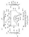
図1は、本発明に係る整列エレメント10を示す全体斜視図、図2は図1の整列エレメントから蓋板を取り外した状態を示す斜視図、図3は図1の整列エレメントに適用される開閉部材の一例を示す図であって、(a)は平面図、(b)は左側面図、(c)は正面図、図4は前記整列エレメント10の構造を示す図であって、(a)は平面図、(b)は正面図、(c)は側面図、(d)はエレメント本体11の作業側部11a付近を示す拡大側断面図、図5は前記整列エレメント10の構造を示す図であり、(a)は取出治具の収容位置付近を示す断面図、(b)は図5(a)のC−C線断面矢視図である。また、図6は、図1の整列エレメントのエレメント本体の変形例を示す斜視図、図7は、図6のエレメント本体の開閉部材付近を示す断面図である。また、図8は本発明に係る光配線盤1を示す全体斜視図、図9は前記光配線盤1を示す図であり(a)は正面図、(b)は側面図、図10は図9(b)のA−A線矢視図、図11は図9(a)のB−B線断面矢視図、図12は光配線盤1の成端架2に搭載されるモジュール収容ユニット5を示す斜視図、図13はモジュール収容ユニット5を示す図であって(a)は平面図、(b)は正面図、図14はモジュール収容ユニット5を示す側面図(但し、光コネクタアダプタ43の構造を実線で示した)、図15は保留エレメント35を示す斜視図である。Hereinafter, an optical wiring board embodying the present invention will be described with reference to the drawings.
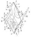
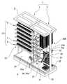
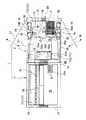
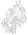
1 is an overall perspective view showing an
まず、本発明に係る光配線盤1の全体構造について説明する。
前記光配線盤1は、本発明に係る整列エレメント10を複数集合させて構成された整列盤33A、33Bを具備するものであり、図8、図9(a)に示すように、成端架2と、この成端架2の隣に横並びに設置された配線架3とを有している。前記整列盤33A、33Bは、配線架3に搭載されている。First, the overall structure of the
The
成端架2は、枠状のフレーム21(以下、架本体)と、この架本体21内に設置された接続盤ユニット22とを有している。前記成端架2は、光ファイバケーブル6の端末が引き込まれるとともに、この光ファイバケーブル6の端末に露出されている光ファイバ61(以下、ケーブル側光ファイバとも言う)を、前記接続盤ユニット22に設けられている光コネクタ42によって、配線架3から引き込まれた光ファイバ(後述の成端光ファイバ71)に対してコネクタ接続可能に成端する機能を果たすものである。
前記接続盤ユニット22の前面側(光配線盤1の前面側。図9(a)紙面手前側、図11左側)と、背面側(光配線盤1の背面側。図9(a)紙面奥側、図11右側)とには、ケーブル側光ファイバ61をコネクタ接続可能に成端するための光コネクタ42(ここでは光コネクタアダプタであり、以下、光コネクタ42を光コネクタアダプタという場合もある)が複数設置されている。図示例の光配線盤1において、接続盤ユニット22の前記光コネクタ42は、接続盤ユニット22に複数収容された光モジュール4の側部に取り付けられたものである。接続盤ユニット22及び光モジュール4の構成については、後に詳述する。The
The front side of the connection board unit 22 (front side of the
ここで、「コネクタ接続可能に成端」(以下、コネクタ成端とも言う)という言葉の意味は、光ファイバの先端に光コネクタを取り付ける行為を指す。光ファイバの先端に取り付ける光コネクタとしては、光コネクタプラグの他、光コネクタレセプタクル等も含まれる。また、本明細書では、光ファイバ先端の光コネクタプラグを光コネクタアダプタ(例えば、光コネクタアダプタである前述の光コネクタ42)などといったハウジングに組み込んで組み立てたユニットも、光ファイバをコネクタ成端する光コネクタと称することとする。また、本明細書では、すでにコネクタ成端されている光ファイバを、光ファイバの先端(コネクタ成端されていない先端)に融着接続やメカニカルスプライスを用いた機械的接続等によって接続することも、結果的に、光ファイバが、コネクタ成端済みの光ファイバに取り付けられている光コネクタによって、コネクタ成端されることになるので、コネクタ成端済みの光ファイバに取り付けられた光コネクタを、コネクタ成端されていない光ファイバの先端をコネクタ成端するための光コネクタとして扱う。
コネクタ接続可能に成端された光ファイバは、当該光ファイバ先端の光コネクタを別の光コネクタと接続(前記受け側光コネクタへの光コネクタプラグの挿入)することで、別の光ファイバの側の光回線との光接続が実現される。また、ここでは、受け側光コネクタに対する光コネクタプラグの接続は、着脱可能であるものとする。Here, the meaning of the term “terminated so that the connector can be connected” (hereinafter also referred to as connector termination) refers to the act of attaching the optical connector to the tip of the optical fiber. The optical connector attached to the tip of the optical fiber includes an optical connector receptacle and the like in addition to the optical connector plug. Further, in this specification, a unit in which an optical connector plug at the tip of the optical fiber is assembled in a housing such as an optical connector adapter (for example, the above-described
An optical fiber terminated to be connectable to a connector can be connected to another optical connector by inserting the optical connector at the tip of the optical fiber (inserting an optical connector plug into the receiving optical connector). The optical connection with the optical line is realized. Here, it is assumed that the connection of the optical connector plug to the receiving side optical connector is detachable.
前述のケーブル側光ファイバ61について説明すれば、前記接続盤ユニット22の光コネクタ42は、成端光ファイバ71の先端に取り付けられた光コネクタ72(光コネクタプラグ)が挿入して接続される光コネクタアダプタあるいは光コネクタレセプタクルといった受け側光コネクタ(光コネクタ)である。この受け側光コネクタをケーブル側光ファイバ61の先端に直接取り付けるか、あるいは、この受け光コネクタが一端に取り付けられている光ファイバの他端側にケーブル側光ファイバ61を光接続することで、ケーブル側光ファイバ61のコネクタ成端が実現される。成端光ファイバ71先端に取り付けられた光コネクタ72(光コネクタプラグ)の光コネクタ42への挿入、接続によって、ケーブル側光ファイバ61と成端光ファイバ71との光接続が実現される。 The above-described cable side
前面側接続盤23及び背面側接続盤24は、それぞれ、架本体21に上下多段に取り付けた複数のモジュール収容ユニット5によって構成されている。モジュール収容ユニット5は、外観薄板状に形成された光モジュール4を縦置き横並びの配列状態に複数収容している。このモジュール収容ユニット5の構成については、後に詳述する。図示例の光配線盤1では、前面側接続盤23、背面側接続盤24のいずれも、架本体21に6段搭載されたモジュール収容ユニット5によって構成されているが、前面側接続盤23及び背面側接続盤24を構成するモジュール収容ユニット5の数はこれに限定されず、それぞれ変更可能である。
但し、前面側接続盤23及び背面側接続盤24は、成端架2の下部に確保したケーブル収容空間25よりも上に設けられる。The front-
However, the front-
図12、図13(a)、(b)、図14に示すように、モジュール収容ユニット5は枠状のモジュール収容部51を有しており、このモジュール収容部51内に前記光モジュール4を縦置き横並びの配列状態に複数収容している。
図12、図14に示すように、光モジュール4は、外観薄板状に形成された扁平ケース状のモジュール本体41の一端部(前端部。側部の一部)に光コネクタ42、43(ここではその形状により光コネクタアダプタあるいは光コネクタレセプタクルであるが、光コネクタレセプタクルの場合も、光コネクタアダプタとも言うことがある)が実装された構造である。
前面側接続盤23においては、光モジュール4は、光コネクタアダプタ42、43が、光配線盤1の前面側(図9(a)紙面手前側、図11左側)となる向きでモジュール収容ユニット5のモジュール収容部51内に収容される。一方、背面側接続盤24においては、光モジュール4は、光コネクタアダプタ42、43が、光配線盤1の背面側(図9(a)紙面奥側、図11右側)となる向きでモジュール収容ユニット5のモジュール収容部51内に収容される。
なお、図12中、符号42aはキャップであり、光コネクタアダプタ42に離脱可能に装着してある。光コネクタアダプタ42からキャップ42aを取り外せば、光コネクタアダプタ42への成端光ファイバ71先端の光コネクタ72の挿入及び接続が可能となる。As shown in FIGS. 12, 13 (a), 13 (b), and 14, the
As shown in FIGS. 12 and 14, the
In the front-
In FIG. 12,
前面側接続盤23は、光配線盤1の前面側からのモジュール収容ユニット5(詳細にはモジュール収容部51)への光モジュール4の挿入、モジュール収容ユニット5から光配線盤1の前面側への光モジュール4の引き出しが可能である。背面側接続盤24は、光配線盤1の背面側からのモジュール収容ユニット5(詳細にはモジュール収容部51)への光モジュール4の挿入、モジュール収容ユニット5から光配線盤1の背面側への光モジュール4の引き出しが可能である。以下、前面側接続盤23のモジュール収容ユニット5に対する光モジュール4の出し入れが行われる前面側(光配線盤1の前面側)を、(前面側接続盤23についての)作業面側とも言う。また、以下、背面側接続盤24のモジュール収容ユニット5に対する光モジュール4の挿入、引き出しが行われる背面側(光配線盤1の背面側)を、(背面側接続盤24についての)作業面側とも言う。また、以下、モジュール収容ユニット5が搭載されている接続盤が前面側接続盤23、背面側接続盤24のいずれであっても、モジュール収容ユニット5から光モジュール4が引き出される側を、モジュール収容ユニット5の作業面側として説明する。 The front-
前面側接続盤23、背面側接続盤24のモジュール収容ユニット5への作業面側からの光モジュール4の挿入は、図14に示すように、モジュール収容ユニット5(詳細にはモジュール収容部51)の作業面側から見て奥行き方向最深部に設けられているストッパ部材52に、光モジュール4の前記前端部とは反対側の後端部が突き当たったところで、それ以上の押し込みが規制され、挿入限界となる。モジュール収容ユニット5に対する光モジュール4の挿入、引き出しの作業は、作業面側からのみ可能である。
なお、ストッパ部材52は、光モジュール4が当接されることでモジュール収容ユニット5に対する光モジュール4の挿入限界を決める機能を果たすものであれば良く、必ずしも、光モジュール4の後端部に当接するものである必要は無い。As shown in FIG. 14, the
The
図11、図14に示すように、前面側接続盤23のモジュール収容ユニット5と背面側接続盤24のモジュール収容ユニット5とは、成端架2の奥行き方向(前後方向。図11左右方向)の中央部にて突き合わせるようにして近接配置されている。
本発明に係る接続盤ユニット22としては、例えば、前面側接続盤23のモジュール収容ユニット5と背面側接続盤24のモジュール収容ユニット5との間に、光ファイバケーブルの挿通等に利用される空間を確保した構成等も採用することができる。但し、前面側接続盤23のモジュール収容ユニット5と背面側接続盤24のモジュール収容ユニット5とを突き合わせるように近接配置する構成であれば、接続盤ユニット22の成端架2の奥行き方向寸法を出来るだけ小さくできる利点がある。As shown in FIGS. 11 and 14, the
As the
成端架2には光ファイバケーブル6が引き込まれる。光ファイバケーブル6は、成端架2のケーブル収容空間25に引き込まれ、このケーブル収容空間25内に設けられているケーブル固定具25aによって固定される。但し、光ファイバケーブル6の成端架2への引き込み位置は、必ずしもケーブル収容空間25である必要は無く、例えば、成端架2の上にケーブル固定具25aを取り付けた固定棚を設けて、この固定棚に引き込む構成等であっても良い。 An
光ファイバケーブル6の端末に露出された光ファイバ61(以下、ケーブル側光ファイバとも言う)は、前面側接続盤23あるいは背面側接続盤24に引き込まれ、光モジュール4の光コネクタアダプタ42によって、配線架3から成端架2に引き込まれる光ファイバ71(後述)先端の光コネクタ72に対してコネクタ接続可能に成端される(図14参照)。
図9(a)、図10等に示すように、ケーブル側光ファイバ61は、ケーブル収容空間25から光配線盤1の中央部に確保された余長収容空間34(後述)を経由して、接続盤ユニット22の側部(配線架3側の側部)から目的のモジュール収容ユニット5に引き込まれる。図示例では、ケーブル側光ファイバ61として、先端が、光コネクタ62(光コネクタプラグ)によってコネクタ接続可能に成端されたコネクタ付き光ファイバを例示しており、光モジュール4の光コネクタアダプタ43に押し込むだけで、ケーブル側光ファイバ61と光モジュール4内の光ファイバ44との光接続が実現されるようになっている。光モジュール4内の光ファイバ44は、一端が光コネクタアダプタ42に接続され、他端が光コネクタアダプタ43に接続されており、光コネクタアダプタ43にて、この光ファイバ44にケーブル側光ファイバ61を接続すると、ケーブル側光ファイバ61が光ファイバ44を介して光コネクタアダプタ42によって、成端光ファイバ71に対してコネクタ接続可能に成端されることとなる。An
As shown in FIG. 9A, FIG. 10 and the like, the cable side
図14に示す例を具体的に説明すると、ケーブル側光ファイバ61として多心光ファイバテープ心線を採用しており、ケーブル側光ファイバ61先端を成端する光コネクタ62として、MT形光コネクタ(MT:Mechanically Transferable。JIS C 5981に制定されるF12形光コネクタ)にて用いられる光コネクタフェルール(以下、MT形光コネクタという)を採用している。光モジュール4内に収容されている光ファイバ44は、光コネクタ62と同じ心数の多心用のMT形光コネクタである光コネクタ44aによって先端がコネクタ接続可能に成端された多心光ファイバ部44bと、この多心光ファイバ部44bの前記光コネクタ44aとは反対側の端部である分岐部44cから単心分岐された複数本の単心光ファイバ部44dと、各単心光ファイバ部44dの先端に取り付けられた光コネクタ44e(単心光コネクタプラグ)とを有する分岐接続用の光ファイバである。 14 will be described in detail. A multi-core optical fiber ribbon is used as the cable-side
光コネクタ44eは、光モジュール4の内側から光コネクタアダプタ42に接続されている。モジュール収容ユニット5内の光モジュール4の光コネクタアダプタ42に作業面側から成端光ファイバ71(ここでは、単心光ファイバ)先端の光コネクタ72を挿入して接続すると、光コネクタアダプタ42内での光コネクタ44e、72同士の接続によって、光ファイバ44の単心光ファイバ部44dと成端光ファイバ71とが光接続される。光コネクタアダプタ42は、ここではMU形光コネクタ(MU:Miniature-unit Coupling optical fiber connector。JIS C 5983に制定されるF14形光コネクタ)であり、複数対の光コネクタ44e、72同士の接続を実現できる。光ファイバ44の単心光ファイバ部44d先端の光コネクタ44e、及び、成端光ファイバ71先端の光コネクタ72は、光コネクタアダプタ42に接続可能な光コネクタプラグである。 The
一方、光ファイバ44の多心光ファイバ部44b先端の光コネクタ44aは、光コネクタアダプタ43に組み込まれており、作業面側からケーブル側光ファイバ61先端の光コネクタ62が光コネクタアダプタ43に押し込まれることで、光コネクタアダプタ43内で光コネクタ62と接続される。光コネクタ44a、43同士が接続されると、ケーブル側光ファイバ61が光ファイバ44の多心光ファイバ部44bと光接続され、これにより、ケーブル側光ファイバ61が光ファイバ44を介して単心分岐されて、光コネクタアダプタ42によって成端光ファイバ71に対してコネクタ接続可能に成端される。 On the other hand, the
ケーブル側光ファイバ61先端の光コネクタ62は、作業面側から光コネクタアダプタ43に押し込むだけで、光ファイバ44の光コネクタ44aと接続できる。また、光コネクタアダプタ43にケーブル側光ファイバ61先端の光コネクタ62を押し込んだ後、光コネクタアダプタ43に設けられている板バネ状のクリップ43aを回転操作して光コネクタ62と係合させることで、光コネクタアダプタ43内への光コネクタ62の押し込み状態の維持と、光コネクタ44a、62間の突き当て力付与とを実現できる。また、クリップ43aと光コネクタ62との係合は、クリップ43aの回転操作(光コネクタ62に対する係合時とは反対の方向への回転操作)によって簡単に解除することができ、これにより、光コネクタアダプタ43からの光コネクタ62の抜き出し、光コネクタ44aとの接続解除を簡単に実現できる。光コネクタアダプタ43は、光ファイバケーブル6端末に露出された光ファイバ61がコネクタ接続されるケーブル接続用光コネクタとして機能する。 The
なお、光ファイバ44、61、71の心数、光コネクタアダプタ42、43の種類等は、上述した構成のものに限定されず、適宜、変更可能である。また、光モジュール4に設けられる光コネクタ42、43としては、成端光ファイバ71あるいはケーブル側光ファイバ61を光モジュール4内の光ファイバと接続する機能を果たすものであれば良く、光コネクタアダプタに限定されず、例えば、光コネクタレセプタクル等も採用可能である。光コネクタプラグである光コネクタ44a、44e、62、72としては、光コネクタ42あるいは光コネクタ43の種類に対応して接続可能なものを採用することは言うまでも無い。 Note that the number of
図9(a)、(b)等に示すように、配線架3には、例えば、所内に設置された伝送装置(図示略)等と接続されたフロアコードケーブルといった光ファイバケーブル7が、該配線架3の下部に確保されたケーブル収容空間31に引き込まれ、ケーブル収容空間31内に設けられているケーブル固定具32によって固定される。光ファイバケーブル7の端末に露出されている光ファイバ71は、先端が、光コネクタ72(光コネクタプラグ)によってコネクタ接続可能に成端されている成端光ファイバである(以下、この光ファイバを成端光ファイバとも言う)。
配線架3から成端架2に引き込まれる多数本の成端光ファイバ71は、配線架3内に設置されている整列盤33A、33Bに引き通されて整列されるようになっている。配線架3には、二つの整列盤33A、33Bが、配線架3の奥行き方向(図10上下方向、図11左右方向。換言すれば前後方向)に位置をずらして設けられている。整列盤33A、33Bは、配線架3に配線される多数本の成端光ファイバ71を整列させる外観薄板状の整列エレメント10(図1参照)を上下多段に積層した構造であり、多数本の成端光ファイバ71を上下多段に整列させて支持する機能を果たす。この整列盤33A、33Bは、成端架3の上端から中央部までの範囲に設けられている。成端光ファイバ71は、成端架2の接続盤ユニット22と整列盤33A、33Bとの間に確保された余長収容空間34を経由して接続盤ユニット22の目的のモジュール収容ユニット5に引き込まれるようになっている。
なお、整列エレメント10は、これ単独でも本発明に係る整列盤として機能し得る。As shown in FIGS. 9A, 9B, etc., the
A large number of termination
The
配線架3に複数の整列盤33A、33Bを設置した構成であれば、整列盤が一つのみである場合に比べて、整列盤の上下方向寸法を縮小でき(整列盤一つ当たりの整列エレメント10の積層数を少なくできる)、整列盤の設置位置を配線架3の出来るだけ上側とする(最下段の整列エレメント10の位置を出来るだけ上側にする)点で有利である。また、複数の整列盤33A、33Bによって成端光ファイバ71を整列させる構成であれば、成端光ファイバ71の導入本数が多い場合でも整列配線が容易であり、しかも、成端光ファイバ71の移設、撤去等の際に、作業対象の成端光ファイバ71を発見しやすく、作業性を向上できるといった利点がある。 In the configuration in which a plurality of
なお、整列盤33A、33Bは、ケーブル収容空間31の上側に設けられており、整列盤33A、33Bの最下段に引き通される成端光ファイバ71の導入部分の位置(高さ)は、接続盤ユニット22の下端と同じか、あるいは、それよりも上側に位置する。
配線架3に引き込まれる成端光ファイバ71は、光ファイバケーブル7として引き込まれる形態に限定されず、例えば、光ファイバコード等である成端光ファイバ71を直接配線架3に引き込むことも可能である。
図示例の光配線盤1では、成端架2の接続盤ユニット22の側部が配線架3に近接配置されているため、前記余長収容空間34は全体が配線架3内に位置するが、例えば、接続盤ユニット22が成端架2における配線架3側の側部よりも成端架2内側に引き込んだ位置である場合は、余長収容空間34が成端架2と配線架3とに跨って存在する構成や、成端架3側のみに存在する構成も採用できる。The
The termination
In the illustrated
また、図9(b)、図10に示すように、配線架3には、成端光ファイバ71の内、光モジュール4の光コネクタアダプタ42に接続していない成端光ファイバ71(以下、保留光ファイバ712と称する場合がある)の端末を保留するための保留エレメント35が設けられている。図15に示すように、前記保留エレメント35は、成端光ファイバ71先端の光コネクタ72を取り出し可能に収容するケース状の部材であり、図9(b)、図10に示すように、前記配線架3の前面側の開閉扉36の内面側(整列盤33Aに対面される側)と、背面側の開閉扉37の内面側(整列盤33Bに対面される側)とにそれぞれ複数設けられている。これら保留エレメント35は、開閉扉を配線架3の外側に開く(図10仮想線参照)ことで露出させることができ、成端光ファイバ71先端の光コネクタ72の収容及び取り出しを行える。 Further, as shown in FIGS. 9B and 10, the
光配線盤1における整列盤33A、33Bから保留エレメント35までの保留光ファイバ712の配線ルートは、整列盤33A、33Bから接続盤ユニット22に引き込まれる成端光ファイバ71(現用光ファイバ711)の配線ルートとは区分けされている。現用光ファイバ711及び保留光ファイバ712は、長手方向の一部が整列エレメント10に収容されるようにして整列エレメント10に挿通して配線された成端光ファイバ71の整列エレメント10から延出された先端側(光コネクタ72側)の光配線盤1内における配線ルートによって区分けされている。また、現用光ファイバ711及び保留光ファイバ712は、整列エレメント10の振り分け機能によって、それぞれの配線ルートに対応して整列エレメント10から振り分け配線されているが、後述のように、整列エレメント10において、成端光ファイバ71の先端側(光コネクタ72側)を延出させる第1、第2引き出しゲート部13、14を切り換えることで、現用光ファイバ711から保留光ファイバ712への変更、並びに、保留光ファイバ712から現用光ファイバ711への変更を行える。 The wiring route of the holding
次に、本発明に係る整列エレメント10について説明する。
図1〜図5に示すように、整列エレメント10は、外観薄板ケース状のエレメント本体11と、このエレメント本体11の側部に着脱可能に装着された開閉部材16と、エレメント本体11のベース部111(詳細には後述のベース板114)と蓋板112との間に確保された間隙である光ファイバ収容空間113内に収容された取出治具17(後述)とを具備して構成されている。Next, the
As shown in FIGS. 1 to 5, the
エレメント本体11は、プレート状のベース部111と該ベース部111上に装着された蓋板112とからなるコ字形フレーム11Fと、このコ字形フレーム11Fに取り付けられた仕切壁15(後述)とで構成されている。
エレメント本体11のベース部111は、平板状のベース板114と、このベース板114の一側部に立設されたリブ状の側壁部115とを有して構成されている。蓋板112は、ベース部111の側壁部115上に装着することで、ベース板114から間隔をおいてベース板114と並行するようにしてベース部111に取り付けられ、蓋板112とベース板114との間に光ファイバ収容空間113が確保される。The
The
コ字形フレーム11Fの内側の空間、すなわちベース板114と蓋板112との間に確保されたクリアランス(隙間)は、光ファイバが配線される光ファイバ収容空間113として機能する。エレメント本体11の前記側壁部115に沿う延在方向の一端部における前記光ファイバ収容空間113の開口部は、該開口部内に設けられた仕切る仕切壁15によって、二つに仕切られている。具体的には、光ファイバ収容空間113内に配線される光ファイバ(成端光ファイバ71)が通される引き込みゲート部12と第2引き出しゲート部14(後述)とに仕切られている。
引き込みゲート部12は、光ファイバ収容空間113の開口部の内、仕切壁15と側壁部115との間に開口する部分であり、第2引き出しゲート部14は仕切壁15から側壁部115とは反対側に開口する部分である。
一方、エレメント本体11の前記側壁部115に沿う延在方向他端部側(引き込みゲート部12、第2引き込みゲート部14が設けられている一端部とは反対の側)には、光ファイバ収容空間113の開口部である第1引き出しゲート部13が設けられている。The space inside the
The lead-in
On the other hand, the other end of the
整列エレメント10に通される成端光ファイバ71は、全て引き込みゲート部12に通され、この引き込みゲート部12に収容された部分よりも先端側(光コネクタ72)側が、第1引き込みゲート部13又は第2引き込みゲート部14に通して、エレメント本体11から外側に延出される。
引き込みゲート部12は、ベース部111のベース板114と、蓋板112と、仕切壁15と、側壁部115とによって囲まれる内側に成端光ファイバ71を収容するようになっている。第1引き出しゲート部13は、ベース部111のベース板114と、蓋板112と、側壁部115とによって囲まれる内側に成端光ファイバ71を収容するようになっている。第2引き出しゲート部13は、ベース部111のベース板114と、蓋板112と、仕切壁15とによって囲まれる内側に成端光ファイバ71を収容するようになっている。The termination
The lead-in
前記仕切壁15は、図示例の整列エレメント10では、ベース部111と蓋板112との間に介装された状態で、ベース部111と蓋板112にねじ止め固定してエレメント本体11に取り付けたものであるが、本発明に係わる仕切壁としては、これに限定されず、例えば、ベース部111又は蓋板112に突設された突起(例えば、ベース部111又は蓋板112を、突起状の仕切壁が突設された合成樹脂製の一体成形品とすることや、仕切壁がベース部111及び蓋板112の一方のみに固定された部材であること)等であっても良い。 The
エレメント本体11に開閉部材16を装着すると、扁平な筒状体である光ファイバ収容体10aが組み立てられる。前記光ファイバ収容空間113は、この光ファイバ収容体10aの内側を貫通する貫通穴である。この光ファイバ収容空間113は、整列エレメント10を貫通する内部空間全体を指すものである。
図示例の開閉部材16は、コ字形フレーム11Fの「コ字」の開口部(後述の側部開口部11b)に着脱可能に装着される。
扁平筒状の光ファイバ収容体10aの幅方向(図5における断面長手方向)両側(両端)の側壁部の内、一方(幅方向一端側)は前記側壁部115であり、他方(幅方向他端側。換言すればベース部111のベース板114の他側部の側)が着脱可能な開閉部材16である。When the opening / closing
The opening / closing
Of the side wall portions on both sides (both ends) of the flat cylindrical optical fiber housing 10a in the width direction (cross-sectional longitudinal direction in FIG. 5), one side (one end side in the width direction) is the
なお、光ファイバ収容体自体、エレメント本体自体も、本発明に係る整列エレメントとして機能する。
蓋板112は、ベース部111に対して開閉可能であることが好ましい。
また、図1等において、符号18は、この整列エレメント10を配線架3の架本体30(フレーム)に取り付けるための係合片18である。この係合片18は、架本体30の柱30aに対して押し込むだけで係合するラッチ構造になっている。また、この係合片18は、該係合片18の側部から突設されている係合解除レバー18aを操作することで、架本体30に対する係合を解除できるようになっている。The optical fiber container itself and the element body itself also function as the alignment element according to the present invention.
It is preferable that the
Moreover, in FIG. 1 etc., the code |
整列盤33A、33Bは、前記整列エレメント10を上下に複数重ね合わせた構造になっている。
整列エレメント10は、成端光ファイバ71の長手方向の一部をエレメント本体11内に収容するようになっており、成端光ファイバ71のエレメント本体11から延出された先端側(光コネクタ72側)を、光配線盤1内での配線ルートの違い(整列盤から余長収容空間34を経由して成端架2へ現用光ファイバ711を引き込む配線ルートと、整列盤から保留エレメント35に保留光ファイバ712を引き込む配線ルート)に対応させて振り分ける機能と、成端光ファイバ71の配線ルートの切り換えに対応して、成端光ファイバ71のエレメント本体11からの引き出し方向(延出方向)を切り換えるための機能とを具備している。The
The
この整列エレメント10のエレメント本体11内には、成端光ファイバ71(ここでは現用光ファイバ711)が、引き込みゲート部12と第1引き出しゲート部13とに通して、側壁部115に沿わせるようにしてエレメント本体11内に引き通し配線される領域である第1配線収容部10c(第1配線ルート)と、成端光ファイバ71(ここでは保留光ファイバ712)が、引き込みゲート部12と第2引き出しゲート部14とに通して、光ファイバ収容空間113内にU字状に湾曲配線される領域である第2配線収容部10d(第2配線ルート)とが確保されている。
第1配線収容部10cは、引き込みゲート部12から側壁部115に沿って第1引き出しゲート部13まで延在している。
第2配線収容部10dは、引き込みゲート部12付近で、第1配線収容部10cから、エレメント本体11における第1配線収容部10cを介して両側の側部の内の片方の側(後述の作業側部11a)へ分岐され、U字形に湾曲して第2引き出しゲート部14に到達しており、第1配線収容部10cと区分けされている。In the element
The first
10 d of 2nd wiring accommodating parts are one side in the side part of both sides via the 1st
図10に示すように、前記整列エレメント10は、配線架3において、第1引き出しゲート部13が余長収容空間34側、第2引き出しゲート部14及び引き込みゲート部12が反対側となる向きで配置される。
また、前面側の整列盤33Aの整列エレメント10は開閉部材16が配線架2の前面側、前面側の整列盤33Bの整列エレメント10は開閉部材16が配線架2の背面側となる向きで配線架2に設けられる。
前面側の整列盤33Aの整列エレメント10では、引き込みゲート部12が第2引き出しゲート部14よりも配線架3奥行き方向(前後方向)で背面側にずれた所に位置し、背面側の整列盤33Bの整列エレメント10では、引き込みゲート部12が第2引き出しゲート部14よりも配線架3奥行き方向(前後方向)で前面側にずれた所に位置している。As shown in FIG. 10, the
Further, the
In the
なお、整列エレメント10及び光ファイバ収容体10a及びエレメント本体11について、光ファイバ収容空間113の軸方向に沿った方向(すなわち、側壁部115に沿った方向)を延在方向、これに垂直の方向、すなわち、第1配線収容部10cを横切る断面の長手方向(図5左右方向)を幅方向と称することとする。また、ここでは、整列エレメント10の厚み方向、すなわち、図1上下方向、図4(b)上下方向、図4(c)左右方向、図5(a)、(b)上下方向を上下方向(ベース部111が下側、蓋板112が上側)と称することとする。 For the
整列盤33A、33Bから前記接続盤ユニット22に引き込まれて光モジュール4の光コネクタアダプタ42に接続される成端光ファイバ71(現用回線の成端光ファイバ。以下、現用光ファイバ711とも称する)は、第1引き出しゲート部13と引き込みゲート部12とを通るようにして整列エレメント10に引き通される。現用光ファイバ711の内、整列エレメント10内に収容された部分から先端側(光コネクタ72側)は、整列エレメント10の第1引き出しゲート部13から整列エレメント10の外側に延出され、基端側(光ファイバケーブル7側)は引き込みゲート部12から整列エレメント10の外側に延出される。
一方、保留光ファイバ712は、整列エレメント10内に収容された部分から基端側(光ファイバケーブル7側)が引き込みゲート部12から整列エレメント10の外側に延出されることは現用光ファイバ711と同じであるが、先端側(光コネクタ72側)は整列エレメント10の第2引き出しゲート部14から整列エレメント10の外側に延出され、配線架3内での引き回しによって保留エレメント35まで配線される。Terminating
On the other hand, the retention
前記エレメント本体11の幅方向(図5における断面長手方向)の一端部(一側部)は、前記ベース部111の側壁部115によって光ファイバ収容空間113が閉塞されており、光ファイバ収容空間113から整列エレメント10の外側への成端光ファイバ71の離脱が規制されている。一方、エレメント本体11の幅方向他端部(他側部。作業側部11a)の側は、光ファイバ収容空間113の開口部(以下、側部開口部11b)となっている。側部開口部11bは、作業側部11aに沿って、エレメント本体11の延在方向全長にわたって形成されており、作業側部11aの延在方向両端(エレメント本体11の延在方向の両端)では、第1引き出しゲート部13及び第2引き出しゲート部14と連通されている。この側部開口部11bは、第1引き出しゲート部13の内外に成端光ファイバ71を移動するための光ファイバ移動口131と、第2引き出しゲート部14の内外に成端光ファイバ71を移動するための光ファイバ移動口141と、前記第1配線収容部10cの内外に成端光ファイバ71を移動するための光ファイバ移動口と、前記第2配線収容部10dの内外に光ファイバを移動するための光ファイバ移動口とを兼ねる。 One end (one side) of the
前記開閉部材16は、側部開口部11bを塞ぐようにしてエレメント本体11の作業側部11aに着脱可能に装着される。
図1中、2点鎖線で示すように、エレメント本体11から開閉部材16を取り外すと、側部開口部11b全体が開口されて、第1、第2配線収容部10c、10dから整列エレメント10の外側への成端光ファイバ71の取り出し(抜き取り)、及び、整列エレメント10の外側から第1、第2配線収容部10c、10dへの成端光ファイバ71の収容を、側部開口部11bを介して行えるようになる。このため、第1配線収容部10cと第2配線収容部10dとの間での成端光ファイバ71の移設も可能となる。すなわち、エレメント本体11の側部開口部11b経由の成端光ファイバ71の移動によって、保留光ファイバ712の現用光ファイバ711への変更、現用光ファイバ711の保留光ファイバ712への変更を自在に行える。The opening / closing
1, when the opening / closing
一方、開閉部材16をエレメント本体11に取り付けた状態では、エレメント本体11の内部を貫通するようにして引き通し配線されている成端光ファイバ71(現用光ファイバ711)や、第2配線収容部10dに収容されている成端光ファイバ71(保留光ファイバ712)が、エレメント本体11の側部開口部11bから整列エレメント10外側に飛び出たり、不用意に引き出されるといった不都合が、開閉部材16によって防止される。また、開閉部材16が、第1引き出しゲート部13と第2引き出しゲート部14との間を仕切る仕切部材としての機能を果たすため、エレメント本体11内における現用光ファイバ711の配線ルートと保留光ファイバ712の配線ルートとが開閉部材16によって厳密に仕切られて、現用光ファイバ711及び保留光ファイバ712のエレメント本体11内における輻輳を防止できる。
なお、図示例の整列エレメント10では、開閉部材16は、エレメント本体11に装着することで、エレメント本体11の側部開口部11bの内、第2引き出しゲート部14の光ファイバ移動口141から、整列エレメント10の延在方向における中央部までの範囲を塞ぐように設けられるが、これに限定されず、例えば、エレメント本体11の側部開口部11b全体を塞ぐように設けられる構成や、側部開口部11bの内、光ファイバ移動口131、121の間に位置する部分のみを塞ぐ構成等であっても良い。On the other hand, in a state where the opening / closing
In the illustrated
開閉部材16及び該開閉部材16のエレメント本体11に対する取付構造の一例を具体的に説明する。
図3、図4(d)に示すように、前記開閉部材16は、ベース部61と蓋板112との間に挿入される棒状の挿入片161と、この挿入片161の長手方向の片端から前記挿入片161を延長するようにして突設された断面コ字形の外側配置片162とを具備している。外側配置片162は、内側に、エレメント本体11の作業側部11aを収容できる。
この開閉部材16は、挿入片161をベース部61と蓋板112との間に挿入し、外側配置片162の内側に作業側部11aを収容した状態で、エレメント本体11に取り付けられる。エレメント本体11に取り付けた開閉部材16は、挿入片161の両側(図4(d)の左右両側)に突設されたスライド突起163が、ベース部61及び蓋板112の互いに対面する内面側に作業側部11aに沿って延在するようにして形成されているガイド溝117に挿入されるため、このスライド突起163がガイド溝117にガイドされつつ、エレメント本体11の作業側部11aに沿ってスライド移動できる。An example of the opening / closing
As shown in FIGS. 3 and 4D, the opening / closing
The opening / closing
開閉部材16は、ガイド溝117に沿ったスライド移動によって、エレメント本体11の延在方向一端部(ここでは、第2引き出しゲート部14)から抜き出すようにして、エレメント本体11から離脱できる。エレメント本体11のガイド溝117は、延在方向の一端部が第2引き出しゲート部14に開口しているため、ガイド溝117からのスライド突起163の離脱も円滑に行える。
開閉部材16は、逆に、エレメント本体11の延在方向一端部、つまり、第2引き出しゲート部14の側からベース部61と蓋板112との間に挿入片161を挿入し、スライド突起163をガイド溝117に挿入することで、エレメント本体11に装着できる。
すなわち、この整列エレメント10では、エレメント本体11に対する開閉部材16の着脱作業を第2引き出しゲート部14側から行える。なお、外側配置片162の側部にはツマミ164が突設されていて、作業側部11aに沿って開閉部材16のスライド移動させる操作を容易に行えるようになっている。The opening / closing
Conversely, the opening / closing
That is, in this
なお、ガイド溝117は、エレメント本体11の作業側部11aの第2引き出しゲート部14側の端部から、第1引き出しゲート部13付近にてエレメント本体11のベース部61及び蓋板112を作業側部11aからエレメント本体11の幅方向に沿って切り欠いた凹形の凹形切込部118付近まで延在するように形成されており、凹形切込部118から第1引き出しゲート部13側には形成されていない。作業側部11aに沿ってスライド移動される開閉部材16は、凹形切込部118付近にてエレメント本体11内に突設されたストッパ壁116(図5(b)参照)に当接されることで、第1引き出しゲート部13側へのそれ以上の移動が規制される。 The
図示例の整列エレメント10では、第1引き出しゲート部13の光ファイバ移動口131のベース部61及び蓋板112にガイド溝117が形成されていないため、第1引き出しゲート部13の光ファイバ移動口131側からエレメント本体11に対する開閉部材16の着脱作業は行えないが、本発明においては、第2引き出しゲート部14側から着脱作業を行える構成に限定されず、例えば、第1引き出しゲート部13の光ファイバ移動口131のベース部61及び蓋板112にガイド溝117を形成して、第1引き出しゲート部13側から、エレメント本体11に対する開閉部材16の着脱作業を行えるようにすることも可能である。
また、図示例の整列エレメント10では、エレメント本体11に形成したガイド溝117によって開閉部材16をガイドする構成を例示したが、これに限定されず、エレメント本体11の作業側部11aに沿って形成したガイド突条によって、開閉部材16を作業側部11aに沿ってスライド移動自在にガイドする構成等も採用可能である。
また、エレメント本体11に対して開閉部材16を着脱可能に装着するための取付構造としては、前述のような、ガイド溝117あるいはガイド突条を利用したスライド移動によるものに限定されず、例えば、係合爪を利用したものや、エレメント本体11と開閉部材16とに離脱可能に刺し通すピンを利用した閂状の係止構造等も採用可能である。係合爪を利用した取付構造としては、例えば、開閉部材16をエレメント本体11の側方から側部開口部11bに押し込むことで、開閉部材16あるいはエレメント本体11に突設された係合爪によって開閉部材16がエレメント本体11に係止され、強制的な引き抜き操作、あるいは、係止解除片の操作によって、係止が解除されて、エレメント本体11から開閉部材16を離脱できる構造などを採用できる。In the illustrated
In the illustrated example of the
Further, the mounting structure for detachably mounting the opening / closing
次に、取出治具17について説明する。
取出治具17は、エレメント本体11の内に配線されている成端光ファイバ71の内、引き出しゲート部11に通されている現用光ファイバ711を作業側部11aからエレメント本体11の外側(図4(a)においては、図中、作業側部11aの下側。作業側部11aの外側を指す。図10においては、図中、前面側の整列盤33Aの下側、背面側の整列盤33Bの上側。以下、作業面側とも言う。)に取り出す作業等に用いることができる。この取出治具17は、エレメント本体11の幅方向に沿って移動自在としてエレメント本体11内に収容されており、エレメント本体11の幅方向に沿った移動によって、エレメント本体11の側部開口部11bから引き出し可能であり、また、エレメント本体11の側部開口部11bから引き出した状態からエレメント本体11に押し込むことも可能である。Next, the take-out
The take-out
図1〜図5に示すように、この取出治具17は、ベース部111上に設置される平板部171aと該平板部171a上に突設された光ファイバ移動片171bとを具備してなる治具本体171上に、脱落防止部材173(後述)等を設けたものである。
光ファイバ移動片171bは、平板部171aの一端部(取出治具17をエレメント本体11に収容したときに、エレメント本体11の側壁部115に対面される端部)上に突設されている。また、脱落防止部材173は、平板部171aの前記一端部とは反対の側である他端部に取り付けられている。
前記取出治具17は、平板部171aの一端部(前記光ファイバ移動片171bが突設されている端部)がエレメント本体11の幅方向一端側(側壁部115の側)、平板部171aの他端部がエレメント本体11の幅方向他端側(作業側部11aの側)となる向きでエレメント本体11内に収容される。As shown in FIGS. 1 to 5, the take-out
The optical
In the
なお、取出治具17の治具本体171については、以下、エレメント本体11の幅方向に沿った方向を「延在方向」として説明することとする。
治具本体171は、単独で、本発明に係る取出治具として機能し得るものであり、本発明に係る取出治具としては、治具本体171のみによって構成されているものも採用可能である。
また、図5(a)等では、平板部171aと光ファイバ移動片171bとが一枚の金属板によって形成された一部品になっている構成の治具本体171を例示しているが、本発明では、これに限定されず、平板部171aに、これとは別部材の光ファイバ移動片171bを固定した構成も採用可能である。The jig body 171 of the take-out
The jig body 171 can function alone as the take-out jig according to the present invention, and as the take-out jig according to the present invention, one constituted only by the jig main body 171 can be adopted. .
Further, in FIG. 5A and the like, a jig body 171 having a configuration in which the flat plate portion 171a and the optical
この取出治具17のエレメント本体11における収容位置は、第1引き出しゲート部13内、第2引き出しゲート部14内、あるいは、第1引き出しゲート部13と第2引き出しゲート部14との間のいずれであっても良いが、図示例の整列エレメント10では、第1引き出しゲート部13と第2引き出しゲート部14との間であり、第1引き出しゲート部13に対して、エレメント本体11の延在方向一端側、つまり、第2引き出しゲート部14及び引き込みゲート部12の側に僅かにずれた第1引き出しゲート部13近傍としている。また、この取出治具17の収容位置は、ベース部111及び蓋板112に形成された凹形切込部118の形成位置と重なっている。
なお、図示例の取出治具17の治具本体171の平板部171aは、延在方向に沿って細長い形状に形成されているが(すなわち、延在方向が平板部171aの長手方向)、これに限定されず、例えば、エレメント本体11の延在方向に沿った方向(幅方向)の寸法が延在方向寸法よりも大きいもの等であっても良い。The storage position of the
The flat plate portion 171a of the jig body 171 of the take-out
引き込みゲート部12と第1引き出しゲート部13とに通して整列エレメント10の光ファイバ収容空間113に引き通し配線された成端光ファイバ71(現用光ファイバ172)は、エレメント本体11内に収容された取出治具17の光ファイバ移動片171bと脱落防止部材173との間に通される。したがい、エレメント本体11内に収容されている取出治具17をエレメント本体11の作業面側に引き出すことで、第1引き出しゲート部13に通されている成端光ファイバ71をエレメント本体11の作業側部11aから引き出すことができる。つまり、取出治具17をエレメント本体11の作業面側に引き出すと、現用光ファイバ172が取出治具17の光ファイバ移動片171bによって押し動かされながら取出治具17の移動に追従するようにして移動されるため、作業面側に引き出すことができる。また、成端光ファイバ71は、エレメント本体11の作業面側に引き出した取出治具17上に載ったままの状態で、エレメント本体11の外側に取り出されるため、不用意に落下させて傷める、といった不都合を生じにくい。このとき、光ファイバ移動片171b及び脱落防止部材173は、取出治具17からの成端光ファイバ71の脱落を防止する機能を果たす。治具本体171は、成端光ファイバ71が載せられる載せ台として機能する。
一方、成端光ファイバ71を、取出治具17の光ファイバ移動片171bと脱落防止部材173との間に通して治具本体171上に載せた状態で、取出治具17を作業面側から光ファイバ収容空間113へ押し込んで行くと、脱落防止部材173によって成端光ファイバ71を押圧しつつ光ファイバ収容空間113内に移動していくことができ、光ファイバ収容空間113内に成端光ファイバ71を収容する作業を簡単に行うことができる。
なお、脱落防止部材173は、省略することも可能である。The terminated optical fiber 71 (working optical fiber 172) that passes through the lead-in
On the other hand, with the termination
Note that the
図示例の取出治具17の光ファイバ移動片171bは、治具本体171の延在方向一端部にて平板部171a上に立ち上げられた立上部171dと、この立上部171dの平板部171aからの突出先端から治具本体171の延在方向他端側に向けて平板部171aと平行に延出する押さえ板部171eとを有する鉤状になっている。取出治具17をエレメント本体11の作業側部11aからエレメント本体11の外に引き出すと、第1引き出しゲート11に通されている成端光ファイバ71が、平板部171aと光ファイバ移動片171bとによって囲まれる内側の領域に収容された状態で、エレメント本体11の作業側部11aに引き出されてくる。この光ファイバ移動片171bは、エレメント本体11の作業面側に引き出された取出治具17上から成端光ファイバ71が不用意に脱落してしまうといった不都合を防止する機能を果たす。 The optical
治具本体171(具体的には平板部171a)の延在方向他端部は、取出治具17をエレメント本体11の幅方向に移動させるための操作ハンドルとして機能させることができる。
図示例の整列エレメント10では、治具本体171(具体的には平板部171a)の延在方向他端部と、脱落防止部材173に取り付けた補助板174とを、前記操作ハンドル178として機能させている。
脱落防止部材173は、治具本体171の平板部171aの延在方向他端部の先端よりも、治具本体171の延在方向一端部側(つまり、光ファイバ移動片171bの側)にずれた位置に固定されている。したがい、治具本体171は、脱落防止部材173を介して光ファイバ移動片171bとは反対の側に突出する突出部171c(長手方向他端部の先端)を有している。
補助板174は、脱落防止部材173に、治具本体171とは反対側となる位置で固定され、治具本体171の平板部171aと平行に設けられている。具体的には、ブロック状の脱落防止部材173と、この脱落防止部材173の両側に配置された補助板174及び治具本体171とを、治具本体171、脱落防止部材173、補助板174に刺し通したねじ175によって一括固定しているが、脱落防止部材173及び補助板174を治具本体171に固定する手法としては、これに限定されず、例えば、接着剤を用いた接着固定や、嵌合等の機械的固定等、様々なものを採用できる。補助板174は、脱落防止部材173から光ファイバ移動片171bとは反対の方向に、平板部171aに平行に延出する突出部174aを有している。なお、補助板174は、脱落防止部材173から平板部171aの延在方向一端部側には突出していない。The other end in the extending direction of the jig main body 171 (specifically, the flat plate portion 171a) can function as an operation handle for moving the
In the illustrated
The drop-
The
取出治具17のエレメント本体11の幅方向に沿った方向の寸法(換言すれば、図示例の整列エレメント10では治具本体171の延在方向寸法と一致)は、エレメント本体11の幅方向寸法からベース部111の側壁部115の厚みを除いた寸法とほぼ一致されている。エレメント本体11に収容した取出治具17の治具本体171の延在方向一端部をエレメント本体11の側壁部115に突き当てると、前記突出部171c、174aの脱落防止部材173からの突出先端がエレメント本体11の作業側部11aに配置されて、突出部171c、174aを、作業者が手指で把持して取出治具17をエレメント本体11の幅方向に沿って移動操作するための操作ハンドル178として機能させることができる。 The dimension in the direction along the width direction of the
図5(a)、(b)に示すように、治具本体171の平板部171a及び前記補助板174は、エレメント本体11のベース部111(詳細にはベース板114)及び蓋板112の互いに対面する内面側に、エレメント本体11の幅方向に沿って延在形成された治具ガイド溝119a、119bに収容されている。取出治具17のエレメント本体11の幅方向に沿った移動は、平板部171a及び前記補助板174と治具ガイド溝119a、119bの内面との摺動によって、エレメント本体11にガイドされつつ円滑になされる。 As shown in FIGS. 5A and 5B, the flat plate portion 171a and the
具体的には、治具本体171の平板部171aは、ベース部111のベース板114に形成された治具ガイド溝119aに収容され、補助板174は、蓋板112に形成された治具ガイド溝119bに収容されている。治具ガイド溝119a、119bは光ファイバ収容体10aの光ファイバ収容空間113を介して丁度対面する位置に形成されている。エレメント本体11のベース部111のベース板114及び前記蓋板112にそれぞれ形成されている凹形切込部118は、治具ガイド溝119a、119bの溝幅方向(エレメント本体の延在方向に一致)の中央部に位置しており、前記治具ガイド溝119a、119bの溝幅方向の両端は、凹形切込部118から両側に張り出している。
ここで、エレメント本体11のベース部111と蓋板112とが、取出治具17をガイドするガイド部材として機能するが、ベース部111及び蓋板112の一方のみがガイド部材としての機能を果たすようになっていても良い。また、ガイド部材としては、別途、光ファイバ収容空間113内に設けた部材であっても良い。また、平板部171a及び前記補助板174は、ガイド部材に摺動する摺動部材として機能するが、摺動部材としては、平板部171a及び前記補助板174に限定されず、例えば、補助板174を省略して脱落防止部材173自体を摺動部材として機能させたり、あるいは、治具本体171に別途取り付けた部材を摺動部材として機能させることも可能である。Specifically, the flat plate portion 171 a of the jig body 171 is accommodated in a
Here, the
エレメント本体11に装着した開閉部材16は、エレメント本体11の作業側部11aに沿ったスライド移動によって、外側配置片162を、エレメント本体11の凹形切込部118の作業面側(エレメント本体11の作業面側)に配置することができる。これにより、開閉部材16を、エレメント本体11の光ファイバ収容空間113内に収容しておいた取出治具17がエレメント本体11の作業面側に不用意に引き出されたり飛び出したりすることを防止するストッパとして機能させることができ、エレメント本体11内に取出治具17が収容された状態を安定に維持できる。 The opening / closing
具体的には、治具本体171の延在方向一端部をベース部111の側壁部115に突き当てて、取出治具17をエレメント本体11内に収容すれば、治具本体171及び補助板174の突出部171c、174aの先端の位置が、エレメント本体11のベース部111及び蓋板112の作業側部11a側の端部に揃えられ、開閉部材16のエレメント本体11の作業側部11aに沿ったスライド移動によって、開閉部材16の断面コ字形の外側配置片162を、治具本体171及び補助板174の突出部171c、174aの先端を作業面側から覆う位置に配置できる。断面コ字形の外側配置片162は、エレメント本体11の作業側部11aに作業面側から被せるようにして装着され、この装着状態を保ったまま、開閉部材16のエレメント本体11の作業側部11aに沿ったスライド移動によって、作業側部11aに沿ってスライド移動するようになっている。そして、外側配置片162が凹形切込部118に移動されると、外側配置片162の内側に、治具本体171及び補助板174の突出部171c、174aの先端が収容され、外側配置片162が、エレメント本体11の作業面側への取出治具17の突出を規制するストッパとして機能するようになる。
なお、開閉部材16は、スライド突起163が、ベース部111及び蓋板112のガイド溝117の端部に設けられたストッパ壁116(図5(d)参照)に当接すると、外側配置片162が凹形切込部118の作業面側の開口部を覆う位置に配置されるようになっている。Specifically, if one end of the jig body 171 in the extending direction is abutted against the
Note that the opening / closing
また、開閉部材16のエレメント本体11の作業側部11aに沿ったスライド移動によって、前記外側配置片162を凹形切込部118の作業面側の開口部を覆う位置に移動していくと、前記外側配置片162の内面側(具体的には、断面コ字形の外側配置片162の両側壁162aの互いに対面する内面側)に形成されている突条収容溝165(図4(d)参照)に、治具本体171及び補助板174の突出部171c、174aの先端に突設されているガイド突条176が収容され、外側配置片162が取出治具17の操作ハンドル178に嵌合する。図4(d)、図5(a)、(b)に示すように、取出治具17の平板部171a及び補助板174に突設されたガイド突条176は、丁度、エレメント本体11の凹形切込部118に露出するところに位置しており、平板部171a及び補助板174から凹形切込部118を介してエレメント本体11の両側(上下両側)に突出されている。従い、開閉部材16のエレメント本体11の作業側部11aに沿ったスライド移動によって、前記外側配置片162を凹形切込部118の作業面側の開口部を覆う位置に移動していくと、エレメント本体11の作業側部11aに内面を摺動させつつ移動する外側配置片162の突条収容溝165内に取出治具17のガイド突条176が収容される。
これにより、エレメント本体11の側部開口部11b内に挿入片161が保持された着脱仕切片16によって、取出治具17がガタ付かないように安定に保持される。取出治具17の安定保持は、整列エレメント10内の成端光ファイバ71が活線状態にあるときに、この成端光ファイバ71による光通信に振動による悪影響を与えないようにする点で有利である。When the
Accordingly, the take-out
図示例の取出治具17では、平板部171a及び補助板174の突出部171c、174aの外面側に、前記ガイド突条176が突設されている突条付きプレート177を被着して、平板部171a及び補助板174にガイド突条176を設けた構成になっているが、これに限定されず、例えば、平板部171a及び補助板174に直接、接着剤による接着や、溶接等によってガイド突条176となる条体を固定した構成や、平板部171a及び補助板174の一部曲げ加工等によってガイド突条176を設けた構成等も採用可能である。
取出治具17の平板部171a及び補助板174に被着された突条付きプレート177は、取出治具17をエレメント本体11内に収容したときに、丁度、凹形切込部118内に配置されるようになっており、エレメント本体11の幅方向への取出治具17の移動の障害にはならない。In the take-out
The
開閉部材16の外側配置片52の形状は、エレメント本体11の作業面側への取出治具17の突出を規制するストッパ機能を満たす点では、必ずしも、コ字形である必要は無く、取出治具17の操作ハンドル178の形状に応じて、ストッパ機能を満たす形状であれば良く、各種形状を採用できる。
また、取出治具17の安定保持の機能を満たすための開閉部材16の構造としては、必ずしも、上述した構造に限定されず、例えば、係合爪によって、取出治具17に対して係脱可能に係合される構造等、各種構造を採用できる。The shape of the
Further, the structure of the opening / closing
また、第1配線収容部10c(及び第1引き出しゲート部13)と第2配線収容部10d(及び第2引き出しゲート部14)との間での成端光ファイバ71の移動を行うために、凹形切込部118の作業面側に配置されていた開閉部材16を、エレメント本体11の作業側部11aに沿ったスライド移動によってエレメント本体11から離脱させてしまえば、エレメント本体11からの取出治具17の引き出しが可能となる。開閉部材16をエレメント本体11から離脱させれば、側部開口部11b全体が開放されるため、エレメント本体11の光ファイバ収容空間113内からエレメント本体11の作業面側への、成端光ファイバ71の取り出し(抜き取り)が可能となることは言うまでも無い。 Further, in order to move the termination
図10に示すように、配線架3の前面側の整列盤33Aに搭載される整列エレメント10は、作業側部11aが配線架3の前面側に臨むように向きを揃えて設けられ、配線架3の背面側の整列盤33Bに搭載される整列エレメント10は、作業側部11aが配線架3の背面側に臨む側となるように向きを揃えて設けられる。配線架3の開閉扉36(または開閉扉37)を開放すれば、各整列盤33A、33Bの整列エレメント10の作業側部11aを露出させることができ、エレメント本体11に対する開閉部材16の着脱操作や、取出治具17の引き出し、再収容等の作業を行える。これにより、現用光ファイバ711から保留光ファイバ712への変更、保留光ファイバ712から現用光ファイバ711への変更を行える。 As shown in FIG. 10, the
前面側の整列盤33Aから延出された保留光ファイバ712は、配線架3の奥行き方向において整列盤33Aよりも前面側に設けられた保留エレメント35まで配線され、背面側の整列盤33Bから延出された保留光ファイバ712は、配線架3の奥行き方向(前後方向)において整列盤33Bよりも背面側に設けられた保留エレメント35まで配線されるようになっており、配線ルートを区別したことにより、前面側の整列盤33Aから延出された保留光ファイバ712と、背面側の整列盤33Bから延出された保留光ファイバ712との輻輳が回避できるようになっている。このため、保留光ファイバ712の本数が多い場合でも、現用光ファイバ711へ変更する保留光ファイバ712の発見、取り出し(抜き取り)、配線ルートの変更等が容易になるといった利点がある。 The holding
すなわち、成端光ファイバ71は、整列盤33A、33Bから接続盤ユニット22に引き込まれる配線ルートと、整列盤33A、33Bから前記保留エレメント35に引き込まれる配線ルートとにそれぞれ対応して、整列エレメント10の第1、第2引き出しゲート部11、12の内の一方を選択して、選択したゲート部から先端側(光コネクタ72側)が延出されるようにして、整列エレメント10に引き通し配線する。これにより、現用光ファイバ711と保留光ファイバ712とが、別々の配線ルートに明瞭に区分けして配線されることとなり、現用光ファイバ711と保留光ファイバ712との輻輳を確実に防止できる。 That is, the termination
上述したように、本発明に係わる整列エレメント(整列エレメント10、光ファイバ収容体10a、エレメント本体11)は、側部開口部11bを介して、第1引き出しゲート部13と第2引き出しゲート部14との間、第1配線収容部10cと第2配線収容部10dとの間での成端光ファイバ71の移動が可能な構造になっている。すなわち、本発明に係わる整列エレメントは、第1、第2引き出しゲート部11、12が設けられているエレメント本体11自体が、エレメント本体11に通した成端光ファイバ71の先端側の配線ルート(引き出し方向)に応じて成端光ファイバ71を引き留める引き留め部として機能するものであり、非常に単純な構造でありながら、異なる複数の配線ルート(換言すれば、エレメント本体11からの引き出し方向。)に対応した成端光ファイバ71の振り分けと、成端光ファイバ71を通す引き出しゲート部の変更(エレメント本体11からの成端光ファイバ71の先端側の引き出し口である複数の引き出しゲート部(ここでは、第1引き出しゲート部13と第2引き出しゲート部14の2つ)間での成端光ファイバ71の移動)とが可能なものである。さらに言えば、本発明に係わる整列エレメントは、エレメント本体11内における成端光ファイバ71の配線ルートの変更(図示例では、第1配線収容部10cと第2配線収容部10dとの間での成端光ファイバ71の移設)により、この成端光ファイバ71を通す引き出しゲート部を変更できるものであり、エレメント本体11の内部の光ファイバ収容空間113を、成端光ファイバ71のエレメント本体11からの引き出し方向の変更、成端光ファイバ71を引き出す引き出しゲート部の変更のために成端光ファイバ71を移動するための空間(移動空間)として利用する構成である。このため、本発明に係わる整列エレメントは、エレメント本体の外側に、成端光ファイバ71の配線ルートに応じて成端光ファイバ71を引き留めるための引き留め部を別途設ける必要が無く、小型化が容易である。従来構成の整列エレメントは、成端光ファイバを収容するエレメント本体の外側に、成端光ファイバの配線ルートに応じて成端光ファイバを引き留めるための引き留め部を別途設けた構成が一般的であり、また、成端光ファイバを配線ルートに応じて振り分けて配線ルート毎に明瞭に区分けするために、引き留め部同士間の距離を充分に確保する必要があるなど、小型化が困難で、大型化しやすいが、本発明に係わる整列エレメントは、このような従来構成の整列エレメントに比べて小型化が容易であることは明らかであり、構造の単純化により、部品点数の減少や、低コスト化も実現できる。また、整列エレメントの小型化により、本発明に係わる整列エレメントを複数重ね合わせた構成の整列盤も小型化することができる。また、この整列盤を搭載した光配線盤では、整列盤の小型化により、収容心数の増大や、高密度化を実現できる。 As described above, the alignment elements (
図6は、整列エレメントのエレメント本体の変形例を示す。
図6に示すエレメント本体11Aは、ベース部111の全体を覆う蓋板112に代えて、ベース部111の側壁部115に沿う延在方向両端のみを覆う形状の蓋板112a、112bを採用したものである。蓋板112a、112bは、引き込みゲート部12、第1、第2引き出しゲート部13、14の構成部材としても機能する。
また、このエレメント本体11Aについては、開閉部材16に代えて、第1、第2引き出しゲート部13、14の光ファイバ移動口131、141のみの開閉を行う開閉部材16Aが設けられている。この開閉部材16Aは、図7に示すように、合成樹脂製の蓋板112a、112bに一体成形された突片であり、薄肉部16A1を介して、蓋板112a、112bから突出ようにして形成されており、薄肉部16A1をヒンジとする回転によって、光ファイバ移動口131、141を開閉できる。また、この開閉部材16Aは、該開閉部材16Aの蓋板112a、112bからの突出先端に形成されている係止片16A2によって、ベース部111に係脱可能に係合できる。
開閉部材16Aは、蓋板112a、112b側に代えてベース部11に設けられていても良いし、ベース部811及び蓋板812の両方に設けられていても良い。また、開閉部材16Aは、必ずしも、蓋板112a、112bあるいはベース部11に一体成形されている必要は無く、例えば、ヒンジを介して、蓋板112a、112bあるいはベース部11に回転自在に取り付けたもの等であっても良い。FIG. 6 shows a modification of the element body of the alignment element.
The
In addition, the element
16 A of opening / closing members may be provided in the
次に、モジュール収容ユニット5について説明する。
図12、図14に示すように、光配線盤1の成端架2に搭載されているモジュール収容ユニット5は、前記モジュール収容部51と、このモジュール収容部51から前記光モジュール4の光コネクタアダプタ42に対する成端光ファイバ71の切替接続作業が行われる作業面側に突設された成端光ファイバ用ダクト53と、前記モジュール収容部51の下に設けられたケーブル側光ファイバ用ダクト54とを有している。成端光ファイバ用ダクト53は、ケーブル側光ファイバ用ダクト54よりも作業面側に位置している。
ケーブル側光ファイバ用ダクト54をモジュール収容部51の下に設けたことは、ケーブル側光ファイバ用ダクト54の全体をモジュール収容部51の作業面側に設置した場合に比べて、モジュール収容ユニット5の奥行き方向の寸法を縮小できる利点がある。Next, the
As shown in FIGS. 12 and 14, the
The provision of the cable-side
成端光ファイバ用ダクト53は、成端架2の左右方向(図9(a)左右)に沿って延在するモジュール収容ユニット5の延在方向に沿って左右に延在されている。この成端光ファイバ用ダクト53には、配線架3から成端架2に引き込まれて光モジュール4の光コネクタアダプタ42に接続された成端光ファイバ71が配線される。なお、図13(a)、図14に示すように、光モジュール4の光コネクタアダプタ42に接続された成端光ファイバ71において、光モジュール4からモジュール収容ユニット5の作業面側に成端光ファイバ用ダクト53まで延びる部分は、成端光ファイバ用ダクト53上に突設されたRガイド56及びクリップ57によって緩やかに湾曲した状態が維持される。クリップ57は、一対の樹脂製線材57aの間に成端光ファイバ71を離脱可能に保持するものであり、同一の光モジュール4に接続されている複数本の成端光ファイバ71を一括保持することができる。 The termination
ケーブル側光ファイバ用ダクト54は、モジュール収容ユニット5に沿って成端光ファイバ用ダクト53と並列に左右に延在されている。このケーブル側光ファイバ用ダクト54には、成端架2に導入された光ファイバケーブル6の端末からモジュール収容ユニット5に引き込まれて光モジュール4の光コネクタアダプタ43に接続されたケーブル側光ファイバ61が配線される。ケーブル側光ファイバ61は、余長収容空間34から目的のモジュール収容ユニット5のケーブル側光ファイバ用ダクト54に引き込まれて、目的の光モジュール4まで配線される。
図14に示すように、ケーブル側光ファイバ用ダクト54は、モジュール収容部51から作業面側に張り出した部分(張出部54a)を有し、ケーブル側光ファイバ61は、上方開放されている張出部54aからモジュール収容ユニット5の作業面側に引き上げるようにして目的の光モジュール4の光コネクタアダプタ43に接続される。The cable-side
As shown in FIG. 14, the cable-side
なお、成端光ファイバ用ダクト53及びケーブル側光ファイバ用ダクト54は、いずれも、樋状に形成されているため、配線された光ファイバ61、71が脱落しにくく、また、ケーブル側光ファイバ61と成端光ファイバ71とが輻輳するといった不都合も確実に防止できる。 The termination
図9(a)に示すように、余長収容空間34には、配線架3から成端架2に引き込まれる成端光ファイバ71の余長71aが収容される。余長収容空間34に収容される成端光ファイバ71の余長71aは、成端光ファイバ71が引き込まれたモジュール収容ユニット5の成端光ファイバ用ダクト53の余長収容空間34側の端部(以下、導入端部53aとも言う)と、整列盤33A、33B(具体的には、整列エレメント10の第1引き出しゲート部13)とから下方に垂れ下げるようにしてU字状に湾曲処理される。また、余長収容空間34は、接続盤ユニット22及び整列盤33A、33Bよりも下方に延在する下部収容空間34aの上下方向寸法により、モジュール収容ユニット5と整列盤33A、33Bとの間に確保した成端光ファイバ71の余長71aが長い場合や、前面側あるいは背面側の接続盤23、24において下部に位置するモジュール収容ユニット5と、整列盤33A、33Bの下部に位置する整列エレメント10との間に確保された余長71aについても、U字状の湾曲処理を確実に行うことができ、配線架3から成端架2に引き込まれる全ての成端光ファイバ71の余長71aについて、モジュール収容ユニット5と整列盤33A、33Bとの間に垂れ下げるようなU字状の湾曲処理を行える。 As shown in FIG. 9A, the surplus
この光配線盤1は、前面側接続盤23と背面側接続盤24とを有しているため、充分な収容心数を確保しつつも、モジュール収容ユニット5の設置位置を出来るだけ光配線盤1の上側とすることが容易であるため、余長収容空間34の下部収容空間34aに充分な大きさ(特に、上下方向寸法)を確保できる。このため、モジュール収容ユニット5の設置位置を出来るだけ光配線盤1の上側として、全ての成端光ファイバ71の余長71aについて、モジュール収容ユニット5と整列盤33A、33Bとの間に垂れ下げるようなU字状の湾曲処理を実現するにしても、モジュール収容ユニット5の設置数を確保でき、収容心数を充分に確保することができる。 Since the
ケーブル側光ファイバ61は、図9(a)、図10に示すように、接続盤ユニット22の余長収容空間34側の側部に設けられているファイバ固定部55によって引き留めることができる。ファイバ固定部55は、モジュール収容ユニット5毎に設置されており、ケーブル側光ファイバ61を、引き込み対象の目的のモジュール収容ユニット5の成端光ファイバ用ダクト53の導入端部53a付近で引き留めることができる。ファイバ固定部55としては、成端光ファイバ71を離脱可能に固定する構造を採用する。図示例のファイバ固定部55は、着脱式の固定部材55a(図9(a)参照)を取り付けることで成端光ファイバ71を離脱可能に固定する構造であるため、切替接続等に伴うモジュール収容ユニット5間での成端光ファイバ71の移設等の作業を行う場合は、ファイバ固定部55から固定部材55aを離脱することで、成端光ファイバ71の固定を簡単に解除でき、作業性確保の点で有利である。また、図8、図10に示すように、ケーブル側光ファイバ61は、前面側接続盤23の各モジュール収容ユニット5に対応して設けられて上下に多段に配列されたファイバ固定部55の列と、背面側接続盤24の各モジュール収容ユニット5に対応して設けられて上下に多段に配列されたファイバ固定部55の列との間に確保された引き込み空間55bを介して、ケーブル側光ファイバ用ダクト54に引き込まれる。
図示例のように、ケーブル収容空間25から前面側接続盤23までのケーブル側光ファイバ61の配線ルートと、ケーブル収容空間25から背面側接続盤24までのケーブル側光ファイバ61の配線ルートとが区分けされている構成であれば、ケーブル側光ファイバ61の本数が多い場合でも、ケーブル側光ファイバ61の輻輳を回避することができ、成端架2に引き込んだ光ファイバケーブル6端末から光モジュール4までケーブル側光ファイバ61を配線する作業や、移設、撤去といった作業の作業性を向上できるといった利点がある。As shown in FIGS. 9A and 10, the cable-side
As in the illustrated example, the wiring route of the cable-side
なお、図示例の光配線盤1では、接続盤ユニット22を構成する前面側接続盤23のモジュール収容ユニット5の上下位置と、背面側接続盤24のモジュール収容ユニット5の上下位置とが揃えられており、前面側接続盤23のモジュール収容ユニット5毎に設けられたファイバ固定部55と、背面側接続盤24のモジュール収容ユニット5毎に設けられたファイバ固定部55とは上下位置が揃えられている。引き込み空間55bを介して横並びに配置されたファイバ固定部55間は後付け可能な連結板55c(図10のみに図示)で連結されることで、一つのユニット(固定部ユニット55d)を構成する。ケーブル側光ファイバ61は、ケーブル収容空間25から、引き込み空間55bを介して横並びに配置された一対のファイバ固定部55と連結板55cとで囲まれる引き込み空間55b、つまり、固定部ユニット55dの内側を経由して、ケーブル側光ファイバ用ダクト54に到達するように配線される。
一方、成端光ファイバ71は、固定部ユニット55dの内側には配線されず、固定部ユニット55dの外側を通るようにして、整列盤33A、33Bからモジュール収容ユニット5の成端光ファイバ用ダクト53に引き込み配線される。このため、余長収容空間34では、ケーブル側光ファイバ61と成端光ファイバ71とが固定部ユニット55dの内外に区分けして配線されるため、輻輳を防止できる。In the illustrated
On the other hand, the termination
この光配線盤1では、配線架3から成端架2に引き込んだ成端光ファイバ71を、前面側あるいは背面側の接続盤23、24のモジュール収容ユニット5の光モジュール4に実装されている光コネクタアダプタ42にコネクタ接続することで、前記光コネクタアダプタ42によってコネクタ接続可能に成端されているケーブル側光ファイバ61と成端光ファイバ71とが光接続され、光ファイバケーブル6側の光線路を、成端光ファイバ71に接続されている伝送装置等と接続できる。成端光ファイバ71は、先端の光コネクタ72によって、光モジュール4の光コネクタアダプタ42に対して切替接続可能であり、これにより、光ファイバケーブル6側の光線路に対する成端光ファイバ71の接続を切り替えることができる。 In this
図10に示すように、配線架3から成端架2に引き込まれる成端光ファイバ71は、余長収容空間34での振り分け配線によって、前面側接続盤23への引き込みと背面側接続盤24への引き込みとを選択できる。したがい、光モジュール4の光コネクタアダプタ42に対する成端光ファイバ71の切替接続を、前面側接続盤23のモジュール収容ユニット5に収容されている光モジュール4の光コネクタアダプタ42と、背面側接続盤24のモジュール収容ユニット5に収容されている光モジュール4の光コネクタアダプタ42との間で行う場合、余長収容空間34での配線ルートの変更によって、前面側接続盤23及び背面側接続盤24の一方から他方へ成端光ファイバ71の引き込み先を変更することで、引き込み先のモジュール収容ユニット5の選択を簡単に行うことができ、切替接続の作業性を確保できる。 As shown in FIG. 10, the terminated
また、この光配線盤1では、成端架2に設置されるモジュール収容ユニット5を、前面側接続盤23と背面側接続盤24とに分けて設置することで、モジュール収容ユニット5の設置位置を出来るだけ光配線盤1の上側として、全ての成端光ファイバ71の余長71aについて、モジュール収容ユニット5と整列盤33A、33Bとの間に垂れ下げるようなU字状の湾曲処理を実現したことにより、成端光ファイバ71の余長処理手法が統一されるため、光モジュール4の光コネクタアダプタ42に対する成端光ファイバ71の切替接続、光モジュール4の光コネクタアダプタ42に接続される成端光ファイバ71(現用光ファイバ711)の増設(保留光ファイバ712を現用光ファイバ711に変更すること等)、撤去(現用光ファイバ711を保留光ファイバ712に変更すること等)等の作業性を確保できる。 Further, in this
(別実施形態)
次に、本発明に係わる整列エレメントの別実施形態を説明する。
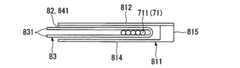
図16は整列エレメント80を示す全体斜視図、図17(a)〜(e)は整列エレメント80の構造を示す図、図18は整列エレメント80のエレメント本体81のベース部811に対して蓋板812を開放した状態を示す展開図、図19はエレメント本体81のベース部811と蓋板812との連結部付近(図18の範囲S)を拡大して示す拡大側面図である。
図16、図17(a)〜(e)に示すように、整列エレメント80は、プレート状のベース部811と該ベース部811上に被せるようにして設けられた蓋板812とを有する外観薄板状のエレメント本体81と、このエレメント本体81のベース部811(詳細にはベース板814)と蓋板812との間に確保された隙間である光ファイバ収容空間82内に収容された取出治具83とを具備している。
この整列エレメント80は、前述の整列エレメント10に代えて、光配線盤1に用いることができる。この整列エレメント80は、上下に複数重ね合わせて整列盤を構成する。
図16等において、符号89は、この整列エレメント80を配線架3の架本体30に取り付けるための係合片である。この係合片89は、架本体30の柱30aに対して押し込むだけで係合するラッチ構造になっている。また、この係合片89は、該係合片89の側部から突設されている係合解除レバー89aを操作することで、架本体30に対する係合を解除できるようになっている。(Another embodiment)
Next, another embodiment of the alignment element according to the present invention will be described.
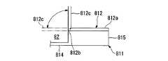
16 is an overall perspective view showing the alignment element 80, FIGS. 17A to 17E are views showing the structure of the alignment element 80, and FIG. 18 is a cover plate for the
As shown in FIGS. 16 and 17A to 17E, the alignment element 80 has an outer thin plate having a plate-
The alignment element 80 can be used in the
In FIG. 16 and the like,
図示例のエレメント本体81のベース部811及び蓋板812は、それぞれ合成樹脂製の一体成形品である。図18、図19に示すように、エレメント本体81のベース部811は、平板状のベース板814と、このベース板814の一側部に沿って立設されたリブ状の突条である側壁部815とを有する板状の部材である。
蓋板812は、ベース部811の側壁部815の上部に固定された固定部812aと、この固定部812aに対して薄肉部812bを介して連結され、ベース板814上を開閉する開閉部812cとを具備して構成されている。前記薄肉部812bは、蓋板812をベース部811に対して回転自在に支持するヒンジとしての機能とを果たす。蓋板812は、前記薄肉部812bを中心とする回転によって、ベース部811に対して開閉可能である。The
The
エレメント本体81は、蓋板812をベース部811上に被せるようにしてベース部811に並行に設けることで、図17(a)〜(e)に示すように薄形ケース状に構成されている。ベース部811(詳細にはベース板814)と蓋板812との間には、光ファイバ収容空間82が確保される。
この整列エレメント80は、成端光ファイバ71の長手方向の途中をエレメント本体81に収容するようになっている。エレメント本体81に通される成端光ファイバ71は、ベース部811(エレメント本体81)の側壁部815に沿う延在方向(図17(a)、(c)、(e)の左右方向、図18左右方向)の一端側(図17(a)、(c)、(e)の右側、図18右側)における前記光ファイバ収容空間82の開口部である引き込みゲート部851に収容するとともに、成端光ファイバ71の前記引き込みゲート部851よりも先端側(光コネクタ72)側が、エレメント本体81の延在方向他端部側における光ファイバ収容空間82の開口部である第1引き出しゲート部852、あるいは、エレメント本体81の延在方向に沿って延在する本体幹部81Aから該本体幹部81Aの側方に延出する第2本体部81Bに設けられた第2引き出しゲート部853からエレメント本体81の外側へ延出するように配線される。
引き込みゲート部851からは、エレメント本体81に収容された成端光ファイバ71の基端側(光ファイバケーブル7側)が延出される。第1引き出しゲート部852(エレメント本体81の他端部)からは、現用光ファイバ711の先端側(光コネクタ72側)が延出される。第2引き出しゲート部853からは、保留光ファイバ712の先端側(光コネクタ72側)が延出される。The element
The alignment element 80 is adapted to accommodate the middle of the termination
From the
ベース部811上に装着された蓋板812は、前記側壁部815と、エレメント本体81の延在方向一端部に確保された引き込みゲート部851(後述)を介して前記側壁部815とは逆の側にてベース部811上に突設された仕切壁88とによって、ベース部811(詳細にはベース板814)に平行に支持される。仕切壁88は、引き込みゲート部851から第2引き出しゲート部853まで延在している。
ベース部811の側壁部815は、光ファイバ収容空間82内に収容した成端光ファイバ71が、エレメント本体81の一側部(図17(b)上側、図17(d)上側)からエレメント本体81の外に出ることを規制する機能を果たす。
なお、エレメント本体81自体も、本発明に係る整列エレメントとして機能する。
また、エレメント本体としては、全体が一体成形されている構成に限定されず、例えば、ベース部と、このベース部とは別体の蓋板がベース部上に装着された構成(蓋板がヒンジでベース部に連結された構成等も含む)等も採用可能である。蓋板はベース部に対して開閉自在であることが好ましい。また、ベース部と蓋板とが別体になっている構成では、ベース部及び蓋板の材質は合成樹脂に限定されず、様々なものを採用できる。
側壁部815は、ベース部及び蓋板に対して別体の部材であっても良い。The
The
The
Further, the element body is not limited to a configuration in which the whole is integrally formed. For example, a configuration in which a base portion and a lid plate separate from the base portion are mounted on the base portion (the lid plate is a hinge) In addition, the structure connected to the base portion may also be adopted. The lid plate is preferably openable and closable with respect to the base portion. In the configuration in which the base portion and the lid plate are separate, the material of the base portion and the lid plate is not limited to the synthetic resin, and various materials can be adopted.
The
図18に示すように、前記ベース部811は、引き込みゲート部851を形成する引き込み台部816と、この引き込み台部816から張り出すように延出された第1ベース部817と、前記引き込み台部816から前記第1ベース部817とは別の方向に張り出すように延出された第2ベース部818とで構成されている。ベース部811の前記側壁部815は、引き込み台部816と第1ベース部817とで構成される幹部819の延在方向(図18左右)に沿って延在する突条状に形成されている。第2ベース部818は、引き込み台部816から前記側壁部815とは逆の方向に延出されている。したがい、ベース部811は、概略L字形に形成されている。
蓋板812は、ベース部811と同様の平面形状を有している。エレメント本体81の平面視形状(図17(c)参照)も、ベース部811の平面視形状にほぼ一致する。
また、以下、エレメント本体81の内、ベース部811の第1ベース部817と、前記蓋板812の内の光ファイバ収容空間82を介して第1ベース部817に対面する部分とによって構成される部分を第1本体部81A2、ベース部811の第2ベース部818と、前記蓋板812の内の光ファイバ収容空間82を介して第2ベース部818に対面する部分とによって構成される部分を第2本体部81Bと称して説明する場合がある。As shown in FIG. 18, the
The
In the following, the
前記エレメント本体81は、引き込みゲート部851が設けられている引き込み本体部81A1と、該引き込み本体部81A1から張り出すようにして延出された第1本体部81A2と、前記引き込み本体部81A1及び前記第1本体部81A2で構成された本体幹部81Aの側方へ前記引き込み本体部81A1から分岐するようにして延出された第2本体部81Bとを具備している。第2本体部81Bは、引き込み本体部81Aから側壁部815とは反対の側へ延出されている。
本体幹部81A内には、前記引き込みゲート部851に通して前記光ファイバ収容空間82内に配線される成端光ファイバ71の内、第1引き出しゲート部852に通される現用光ファイバ711が収容される。第2本体部81B内には、前記引き込みゲート部851に通して前記光ファイバ収容空間82内に配線される成端光ファイバ71の内、第2引き出しゲート部853に通される保留光ファイバ712が収容される。The element
In the main
この整列エレメント80内には、保留光ファイバ712と現用光ファイバ711とが、異なる配線ルートで配線される。
すなわち、光ファイバ収容空間82内における保留光ファイバ712の配線ルートは、引き込み本体部81A1にて、現用光ファイバ711の光ファイバ収容空間82内における配線ルートから分岐されており、本体幹部81Aに引き通し配線される現用光ファイバ711の配線ルートと区分けされている。以下、光ファイバ収容空間82内において、現用光ファイバ711が配線される領域(すなわち、ベース部811上において、引き込みゲート部851と第1引き出しゲート部852とに通して引き通し配線される成端光ファイバ71の配線領域)を第1配線ルート841、保留光ファイバ712が配線される領域(すなわち、ベース部811上において、引き込みゲート部851と第2引き出しゲート部853とに通して配線される成端光ファイバ71の配線領域)を第1配線ルート842と称する。第1配線ルート841及び第1配線ルート842は、光ファイバ収容空間82の一部である。In the alignment element 80, the holding
That is, the wiring route of the reserved
引き込みゲート部851は、ベース部811と蓋板812との間において、側壁部815と仕切壁88との間に確保された開口部である。
引き込みゲート部851は、ベース部111のベース板814及び側壁部815と、蓋板812と、仕切壁88とによって囲まれる内側に成端光ファイバ71を収容する。
第1引き出しゲート部852は、ベース部111のベース板814及び側壁部815と、蓋板812と、開閉部材87(後述)とによって囲まれる内側に成端光ファイバ71を収容する。
第2引き出しゲート部853は、ベース部111のベース板814及び仕切壁88と、蓋板812と、開閉部材87(後述)とによって囲まれる内側に成端光ファイバ71を収容する。
前記仕切壁88は、引き込みゲート部851と第1引き出しゲート部852との間を、成端光ファイバ71が移動できないように仕切る機能と、第1配線ルート842に収容した成端光ファイバ71(保留光ファイバ712)が、エレメント本体81の第2本体部81Bの作業側部81a(後述)とは反対の側から出ることを規制する機能とを果たすものである。The pull-in
The lead-in
The first
The second
The
エレメント本体81の第1本体部81Aと第2本体部81Bとは、前記ベース部811と同様にL字形になっているエレメント本体81の内角側の空間である作業空間86に臨んでいる。
エレメント本体81の他側部(ベース部811の側壁部815がある一側部とは反対の側の側部)の側において、前記作業空間86に臨むエレメント本体81の側部、すなわち、第1引き出しゲート部852から第2引き出しゲート部853にわたって延在するエレメント本体81の側部(以下、作業側部81aとも言う)には、延在方向全長にわたって、光ファイバ収容空間82の開口部である側部開口部81bが開口されている。前記側部開口部81bは、第1引き出しゲート部852の作業空間86側の開口部である光ファイバ移動口と、第2引き出しゲート部853の作業空間86側の開口部である光ファイバ移動口と、第1配線ルート841の作業空間86側の開口部である光ファイバ移動口と、第1配線ルート842の作業空間86側の開口部である光ファイバ移動口として機能する、1本の連続した開口部である。この側部開口部81bは、作業側部81aに沿った延在方向全長にわたって成端光ファイバ71が通過できるように開口されている。The first
On the other side of the element body 81 (on the side opposite to the one side where the
第1引き出しゲート部852の作業空間86側の開口部である光ファイバ移動口852aと、第2引き出しゲート部853の作業空間86側の開口部である光ファイバ移動口853aとには、該光ファイバ移動口852a、853aを開閉する開閉部材87が設けられている。区別のため、図18等においては、第1引き出しゲート部852の光ファイバ移動口852aに設けられた開閉部材87に符号871、第2引き出しゲート部853の光ファイバ移動口853aに設けられた開閉部材87に符号872を付している。また、第1配線ルート841の第1引き出しゲート部852を除く部分についても、作業空間86側の開口部である光ファイバ移動口841aに、開閉部材87(区別のため、符号873を付して説明する場合がある)が開閉可能に設けられている。 The optical
図示例の整列エレメント80では、前記開閉部材87は、図20に示すように、蓋板812の作業側部81a側の端部から突出する突片である。この開閉部材87は、具体的には、薄肉部874を介して蓋板812の開閉部812cと連結されており、薄肉部874を中心とする回転によって開閉される。ここで、開閉部材87は、側部開口部81bの延在方向の一部(具体的には、光ファイバ移動口)を塞いだ状態が「閉」の状態であり、側部開口部81bを開放した状態が「開」の状態である。この開閉部材87は、閉状態としたときに、ベース部811に係脱可能に係合する係合手段を有しており、この係合手段の係合によって閉状態を維持できる。
図18、図20において、具体的には、前記開閉部材87には、ベース部811の作業側部81a側の端部に突設されている係止爪875(弾性爪)を受け容れる係合穴876が形成されており、開閉部材87を前記薄肉部874を中心とする回転によって、ベース部811の作業空間86の側(以下、作業面側とも言う)の端部(作業側部81a)に押し当てて前記係合穴876に前記係止爪875を入り込ませると、前記係止爪875によって開閉部材87がベース部811に係止され、開閉部材87の閉状態が維持される。また、ベース部811に対して係合状態にある開閉部材87を強く引っ張って、開閉部材87を係止爪875から強制的に離脱させれば、開状態とすることができる。係合穴876は、特に必要で無ければ、形成を省略できる。In the alignment element 80 of the illustrated example, the opening / closing
In FIG. 18 and FIG. 20, specifically, the opening / closing
前記係合手段としては、図示例の構成に限定されず、例えば、開閉部材87に突設した係合爪等、各種構成が採用可能である。
開閉部材87は、ベース部811に設けられていても良いし、ベース部811及び蓋板812の両方に設けられていても良い。また、開閉部材87は、必ずしも、エレメント本体81に一体成形されている必要は無く、例えば、ヒンジを介して、エレメント本体81のベース部811又は蓋板812に回転自在に取り付けられたものや、エレメント本体81に作業空間86側からの押し込みによって離脱可能に嵌合又は係合して装着される構造のもの、エレメント本体81の作業側部81aに沿ったスライド移動によってエレメント本体81に対して着脱される構成のもの、等であっても良い。The engagement means is not limited to the configuration shown in the drawing, and various configurations such as an engagement claw protruding from the opening / closing
The opening / closing
この整列エレメント80では、開閉部材871、872を開いて光ファイバ移動口852a、853aを開放することで、側部開口部81b全体を開放することができる。第1引き出しゲート部852の光ファイバ移動口851aの開閉部材871を開いて光ファイバ移動口851aを開放すれば、側部開口部81bを介して、第1配線ルート841から作業空間86への成端光ファイバ71の取り出し作業、及び、作業空間86から第1引き出しゲート部852への成端光ファイバ71の収容作業を行うことができる。第2引き出しゲート部853の光ファイバ移動口853aの開閉部材872を開いて光ファイバ移動口853aを開放すれば、側部開口部81bを介して、第1配線ルート842から作業空間86への成端光ファイバ71の取り出し作業、及び、作業空間86から第2引き出しゲート部853への成端光ファイバ71の収容作業を行うことができる。これにより、第1配線ルート841と第1配線ルート842との間での成端光ファイバ71の移設を作業空間86経由で行うことができ、保留光ファイバ712から現用光ファイバ711への変更、現用光ファイバ711から保留光ファイバ712への変更を行える。
開閉部材87を閉状態とし、第1、第2引き出しゲート部852、853の光ファイバ移動口852a、853aを開閉部材87によって閉じておけば、光ファイバ移動口852a、853aから成端光ファイバ71が抜け出ることが開閉部材87によって規制されることは言うまでも無い。In the alignment element 80, the
When the opening / closing
図21に示すように、取出治具83は、可撓性のシート(例えば合成樹脂製シート。ここでは、所謂フィルム等も含む)によって形成されており、U字状に曲げられて、内側に成端光ファイバ71を収容した状態で、光ファイバ収容空間82に収容されている。図17(c)、図18に示すように、図示例の整列エレメント80では、取出治具83は、光ファイバ収容空間82の内、第1配線ルート841に収容されている。また、取出治具83のU字状に湾曲された部分を介して両側の端部831(両端)は、側部開口部81bを介して作業側部81aから作業空間86に突出されており、この作業空間86に突出された両端が、取出治具83をエレメント本体81から作業面側に引き出すようにして取り出すための操作ハンドルとして機能する。操作ハンドルとして機能する両端部831を、作業者が手指等で引っ張って、取出治具83を作業空間86側に引き出すと、この取出治具83と一緒に、取出治具83の内側に収容されている成端光ファイバ71(現用光ファイバ711)を作業空間86に取り出すことができる(図16の仮想線で示す成端光ファイバ71を参照)。これにより、エレメント本体81からの成端光ファイバ71の取り出しを簡単に行うことができる。 As shown in FIG. 21, the take-out
なお、エレメント本体81における取出治具83の収容位置は、第1配線ルート841に限定されず、第1配線ルート842であっても良く、また、第1配線ルート841と第1配線ルート842の両方であっても良い。
また、取出治具83は、例えば、U字状に湾曲された部分を介して両側の端部の一方(一端)を他方(他端)に連結して、他端のみを前記操作ハンドルとして機能させる構成とすることも可能である。取付治具83の一端を他端に連結する手法としては、例えば、接着剤による接着、熱溶着による固定、クリップ等の固定用の別部材を用いた固定、一端及び/又は他端に形成したスリットや切欠部を利用した係脱可能な係合、などが採用可能である。In addition, the accommodation position of the
In addition, the take-out
この整列エレメント80は、エレメント本体81の第1本体部81Aと第2本体部81Bとの間に、エレメント本体81の作業側部81a側を一部切り欠いた形状の作業空間86が確保されており、側部開口部81b全体がこの作業空間86に開口されていることから、この作業空間86を、第1配線ルート841と第2配線ルート842との間での成端光ファイバ71の移設等の作業に利用することで、整列エレメント80の側部に確保すべき作業スペースを縮小することができる。この作業スペースの縮小は、この整列エレメント80を複数重ね合わせて構成した整列盤についても同様に言える。また、この整列盤を搭載した光配線盤の高密度化を実現できるといった効果も得られる。 In the alignment element 80, a
図22は、この整列エレメントの変形例を示す。
図22に示す整列エレメント80Aは、本体幹部81Aの両側に、引き込み本体部81A1から延出する第2本体部81Bが本体幹部81Aから分岐するように形成されたエレメント本体81’を採用したものである。作業側部81a及び側部開口部81bは、本体幹部81A及び第2本体部81Bの内、本体幹部81Aの両側に確保された作業空間86に臨む部分に設けられている。この場合、本体幹部81Aの内、第1本体部81A2の両側、第1引き出しゲート部852の両側に、光ファイバ移動口を有する構成を採用する。
また、図16、図22等に例示した整列エレメント80、80Aについて、引き込みゲート部、第1、第2引き出しゲート部に対応する部分のみに蓋板を設けた構成を採用することも可能である。FIG. 22 shows a variation of this alignment element.
The
Further, the
なお、本発明は、前述した実施形態に限定されず、各種変更が可能であることは言うまでも無い。
エレメント本体の具体的形状は、本発明の主旨を逸脱しない範囲で、適宜変更できることは言うまでも無い。また、エレメント本体のベース部及び蓋板は、それぞれ、樹脂一体成形品であることが、低コスト化等の点で好ましいが、本発明ではこれに限定されず、複数の部材を用いた組み立て品であっても良い。
また、本発明に係る整列エレメントの適用対象の光配線盤は、上述した実施形態のものに限定されず、様々なものを適用できることは言うまでも無い。また、上述の実施形態では、整列エレメントを、配線架3から成端架2に引き込む成端光ファイバ71の整列に用いた場合を例示したが、本発明に係る整列エレメントの適用対象の光ファイバは成端光ファイバ71に限定されず、光コネクタによる先端のコネクタ成端の有無等に拘わらず、各種の光ファイバの整列や、振り分け配線に用いることができる。Needless to say, the present invention is not limited to the above-described embodiments, and various modifications are possible.
Needless to say, the specific shape of the element body can be changed as appropriate without departing from the gist of the present invention. Further, it is preferable that the base part and the cover plate of the element main body are each a resin-integrated molded product in terms of cost reduction, but the present invention is not limited to this, and an assembled product using a plurality of members. It may be.
Moreover, it goes without saying that the optical wiring board to which the alignment element according to the present invention is applied is not limited to that of the above-described embodiment, and various types can be applied. In the above-described embodiment, the case where the alignment element is used for alignment of the termination
1…光配線盤、2…成端架、22…接続盤ユニット、3…配線架、33A、33B…整列盤、10…整列エレメント、10c…第1配線ルート(第1配線収容部)、10d…第2配線ルート(第2配線収容部)、11…エレメント本体、11A…エレメント本体、11F…コ字形フレーム、11a…作業側部、11b…側部開口部、111…ベース部、112…蓋板、113…光ファイバ収容空間、114…ベース板、115…側壁部、12…引き込みゲート部、13…第1引き出しゲート部、14…第2引き出しゲート部、15…仕切壁、16…開閉部材、17…取出治具、171…治具本体、171a…平板部、171b…光ファイバ移動片、178…操作ハンドル、35…保留エレメント、42…光コネクタ(光コネクタアダプタ)、71…成端光ファイバ、711…成端光ファイバ(現用光ファイバ)、712…成端光ファイバ(保留光ファイバ)、72…光コネクタ(光コネクタプラグ)、80、80A…整列エレメント、81、81’…エレメント本体、81A…本体幹部、81A1…引き込み本体部、81A2…第1本体部、81B…第2本体部、81a…作業側部、81b…側部開口部、811…ベース部、812…蓋板、814…ベース板、815…側壁部、83…取出治具(シート)、831…操作ハンドル(端部)、841…第1配線ルート、842…第2配線ルート、851…引き込みゲート部、852…第1引き出しゲート部、853…第2引き出しゲート部、86…作業空間、87…開閉部材、88…側壁部(仕切壁)。 DESCRIPTION OF
Claims (12)
Translated fromJapanese光ファイバが配線される上面を有するベース板(114、814)と、
このベース板の一端部に設けられ、前記ベース板上に配線される光ファイバが通される引き込みゲート部(12、851)と、
前記ベース板の前記一端部とは反対の側の他端部に設けられ、前記引き込みゲート部に通された光ファイバの内、前記ベース板の前記一端部から前記他端部にわたって引き通す第1配線ルート(10c、841)でベース板に配線される光ファイバが通される第1引き出しゲート部(13、852)と、
前記ベース板の前記第1配線ルートを介して両側又は片側に位置する側部あるいは前記一端部に設けられ、前記引き込みゲート部に通された光ファイバの内、前記引き込みゲート部から前記第1配線ルートとは異なる第2配線ルート(10d、842)でベース板上に配線される光ファイバが通される第2引き出しゲート部(14、853)とを具備し、
前記ベース板の両側又は片側の前記側部の内、第1引き出しゲート部から第2引き出しゲート部にわたって延在する部分である作業側部(11a、81a)には、第1引き出しゲート部の内外に光ファイバを移動するための光ファイバ移動口(131、852a)と、第2引き出しゲート部の内外に光ファイバを移動するための光ファイバ移動口(141、853a)とが設けられ、
第1配線ルート及び第2配線ルートの一方に配線されている光ファイバを前記作業側部からベース板の外側に取り出して、第1配線ルート及び第2配線ルートの他方に移設できるようになっていることを特徴とする整列エレメント(10、80、80A)。An alignment element that is formed into an external thin plate shape and is used for aligning a plurality of optical fibers (71, 711, 712),
A base plate (114, 814) having an upper surface to which the optical fiber is wired;
A lead-in gate portion (12, 851) provided at one end of the base plate and through which an optical fiber wired on the base plate is passed,
A first optical fiber that is provided at the other end of the base plate opposite to the one end and passes from the one end of the base plate to the other end of the optical fiber that is passed through the lead-in gate. A first extraction gate portion (13, 852) through which an optical fiber wired to the base plate through the wiring route (10c, 841) is passed;
Of the optical fibers that are provided on both sides or one end portion of the base plate via the first wiring route and located on one side or the one end, and passed through the drawing gate portion, the first wiring from the drawing gate portion. A second extraction gate part (14, 853) through which an optical fiber wired on the base plate is passed through a second wiring route (10d, 842) different from the route;
Of the side portions on both sides or one side of the base plate, the working side portions (11a, 81a), which are portions extending from the first drawing gate portion to the second drawing gate portion, have inner and outer sides of the first drawing gate portion. An optical fiber moving port (131, 852a) for moving the optical fiber, and an optical fiber moving port (141, 853a) for moving the optical fiber in and out of the second extraction gate portion,
An optical fiber wired to one of the first wiring route and the second wiring route can be taken out of the base plate from the working side and transferred to the other of the first wiring route and the second wiring route. Alignment elements (10, 80, 80A) characterized in that
前記エレメント本体には、前記引き込みゲート部と、前記第1引き出しゲート部と、前記第2引き出しゲート部とが、前記ベース板と前記蓋板との間に確保された光ファイバ収容空間(113、82)の開口部として設けられ、
前記エレメント本体において前記ベース板の前記作業側部に沿って延在する側部(11a、81a)には、延在方向全長にわたって、前記光ファイバ収容空間の開口部である側部開口部(11b、81b)がスリット状に形成されており、
第1配線ルート及び第2配線ルートの一方に配線されている光ファイバを前記側部開口部からベース板の外側に取り出して、第1配線ルート及び第2配線ルートの他方に移設できるようになっていることを特徴とする請求項1記載の整列エレメント。A thin case-shaped element body (11, 11A, 81) configured to include the base plate and a cover plate (112, 812) provided on the base plate at an interval;
In the element body, the drawing gate portion, the first drawing gate portion, and the second drawing gate portion are optical fiber accommodation spaces (113,) secured between the base plate and the lid plate. 82) as an opening,
In the element body, side portions (11a, 81a) extending along the working side portion of the base plate have side openings (11b) that are openings of the optical fiber accommodation space over the entire length in the extending direction. 81b) is formed in a slit shape,
An optical fiber wired to one of the first wiring route and the second wiring route can be taken out of the base plate from the side opening and transferred to the other of the first wiring route and the second wiring route. The alignment element according to claim 1, wherein
ベース板(114)と、このベース板上に間隔をおいて設けられた蓋板(112)と、側壁部(115)とによって断面コ字形に組み立てられ、光ファイバが配線される光ファイバ収容空間(113)が内側に確保されたコ字形フレーム(11F)、及び、該コ字形フレームの前記側壁部に沿う延在方向の一端部における前記光ファイバ収容空間の開口部内に設けられて該開口部を二つに仕切る仕切壁(15)を有する薄形ケース状のエレメント本体(11)を具備し、
前記エレメント本体は、
該エレメント本体の前記側壁部に沿う延在方向の一端部における前記光ファイバ収容空間の開口部の内、前記仕切壁と前記側壁部との間に開口された部分であり、前記光ファイバ収容空間に配線される光ファイバが通される引き込みゲート部(12)と、
前記エレメント本体の延在方向他端部における前記光ファイバ収容空間の開口部であり、前記引き込みゲート部に通された光ファイバの内、前記側壁部に沿って前記光ファイバ収容空間に引き通す第1配線ルート(10c)で配線される光ファイバ(711)が通される第1引き出しゲート部(13)と、
前記エレメント本体の延在方向一端部における前記光ファイバ収容空間の開口部の内、前記仕切壁を介して前記引き込みゲート部と反対の側に開口され、前記引き込みゲート部に通された光ファイバの内、前記引き込みゲート部からU字形に湾曲させる第2配線ルート(10d)で前記光ファイバ収容空間内に配線される光ファイバ(712)が通される第2引き出しゲート部(14)と、
前記エレメント本体の前記側壁部とは反対の側の側部である作業側部(11a)における前記光ファイバ収容空間の開口部であり、第1引き出しゲート部から第2引き出しゲート部にわたって延在する前記作業側部の延在方向全長にスリット状に形成された側部開口部(11b)とを有し、
第1配線ルート及び第2配線ルートの一方から前記側部開口部を介してエレメント本体の外側に取り出した光ファイバを、第1配線ルート及び第2配線ルートの他方に移設できるようになっていることを特徴とする整列エレメント(10)。An alignment element that is formed into an external thin plate shape and is used for aligning a plurality of optical fibers (71, 711, 712),
An optical fiber housing space in which an optical fiber is routed by being assembled in a U-shaped cross section by a base plate (114), a lid plate (112) provided on the base plate at an interval, and a side wall (115). (113) is provided inside the opening of the optical fiber housing space at one end in the extending direction along the side wall of the U-shaped frame (11F) secured inside. A thin case-like element body (11) having a partition wall (15) for partitioning
The element body is
Of the opening portion of the optical fiber housing space at one end portion in the extending direction along the side wall portion of the element body, the portion opened between the partition wall and the side wall portion, and the optical fiber housing space A lead-in gate section (12) through which an optical fiber wired to
An opening of the optical fiber housing space at the other end in the extending direction of the element body, and among the optical fibers passed through the pull-in gate portion, the first through the optical fiber housing space along the side wall portion. A first extraction gate portion (13) through which an optical fiber (711) wired through one wiring route (10c) is passed;
Among the openings of the optical fiber housing space at one end in the extending direction of the element body, the optical fiber is opened on the side opposite to the drawing gate portion through the partition wall and passed through the drawing gate portion. A second drawing gate portion (14) through which an optical fiber (712) wired in the optical fiber housing space is passed through a second wiring route (10d) curved in a U shape from the drawing gate portion;
The opening of the optical fiber housing space in the working side (11a), which is the side opposite to the side wall of the element body, extends from the first draw gate to the second draw gate. A side opening (11b) formed in a slit shape in the entire length of the working side in the extending direction;
An optical fiber taken out from the element main body from one of the first wiring route and the second wiring route through the side opening can be moved to the other of the first wiring route and the second wiring route. An alignment element (10) characterized in that.
ベース板(814)と、このベース板上に間隔をおいて設けられた蓋板(812)と、側壁部(815、88)とによって、前記ベース板と前記蓋板との間に光ファイバが配線される光ファイバ収容空間(82)を有する薄形ケース状に組み立てられたエレメント本体(81)を具備し、
前記エレメント本体は、前記光ファイバ収容空間の開口部である引き込みゲート部(851)が設けられている引き込み本体部(81A1)と、該引き込み本体部から張り出すようにして延出された第1本体部(81A2)と、前記引き込み本体部及び前記第1本体部で構成された本体幹部(81A)の側方へ前記引き込み本体部から分岐するようにして延出された第2本体部(81B)とを具備し、
本体幹部の引き込み本体部とは反対の側の端部には、前記引き込みゲート部に通して前記光ファイバ収容空間内に配線される光ファイバの内、本体幹部内に引き通し配線された光ファイバが通される第1引き出しゲート部(852)が設けられ、
前記第2本体部の前記引き込み本体からの延出方向先端部には、前記引き込みゲート部に通して前記光ファイバ収容空間内に配線される光ファイバの内、第2本体部内に引き通し配線された光ファイバが通される第2引き出しゲート部(853)が設けられ、
前記第1本体部と前記第2本体部との間に挟まれた領域である作業空間(86)に臨む前記エレメント本体の側部である作業側部(81a)には、前記光ファイバ収容空間の開口部である側部開口部(81b)が、前記第1引き出しゲート部から前記第2引き出しゲート部にわたって延在するスリット状に形成され、
前記第1本体部及び前記第2本体部の一方から前記側部開口部を介して作業空間に取り出した光ファイバを、本体幹部及び第2本体部の他方に移設できるようになっていることを特徴とする整列エレメント(80、80A)。An alignment element that is formed into an external thin plate shape and is used for aligning a plurality of optical fibers (71, 711, 712),
An optical fiber is provided between the base plate and the cover plate by the base plate (814), the cover plate (812) provided on the base plate with a space therebetween, and the side wall portions (815, 88). Comprising an element body (81) assembled into a thin case having an optical fiber accommodation space (82) to be wired;
The element body includes a lead body portion (81A1) provided with a lead gate portion (851) which is an opening portion of the optical fiber housing space, and a first extending so as to protrude from the lead body portion. A main body portion (81A2) and a second main body portion (81B) extending so as to branch from the pull-in main body portion to the side of a main body trunk portion (81A) constituted by the pull-in main body portion and the first main body portion. )
Optical fiber routed into the main body trunk of the optical fiber routed in the optical fiber housing space through the pull-in gate portion at the end of the main body trunk opposite to the main body portion A first extraction gate portion (852) through which is passed,
The leading end of the second main body portion extending from the lead-in main body is routed into the second main body portion of the optical fiber that passes through the pull-in gate portion and is routed into the optical fiber housing space. A second extraction gate portion (853) through which the optical fiber is passed,
In the work side part (81a) which is the side part of the element body facing the work space (86) which is a region sandwiched between the first body part and the second body part, the optical fiber housing space is provided. A side opening (81b) that is an opening of the first extension gate portion is formed in a slit shape extending from the first extraction gate portion to the second extraction gate portion,
An optical fiber taken out from one of the first main body and the second main body into the work space through the side opening can be transferred to the other of the main body trunk and the second main body. Characteristic alignment element (80, 80A).
前記取出治具は、前記作業側部からベース板の外側に突出するように配置される操作ハンドル(178、831)を有していることを特徴とする請求項1〜6のいずれかに記載の整列エレメント。On the base plate, an optical fiber wired between the drawing gate portion and the first drawing gate portion or between the drawing gate portion and the second drawing gate portion is moved to the working side portion side. Take-out jigs (17, 83) to be pulled out from the working side,
The said extraction jig has an operation handle (178, 831) arrange | positioned so that it may protrude outside the said base plate from the said operation | work side part. Alignment elements.
Priority Applications (1)
| Application Number | Priority Date | Filing Date | Title |
|---|---|---|---|
| JP2004314709AJP4184329B2 (en) | 2004-10-28 | 2004-10-28 | Alignment element, alignment board, optical distribution board |
Applications Claiming Priority (1)
| Application Number | Priority Date | Filing Date | Title |
|---|---|---|---|
| JP2004314709AJP4184329B2 (en) | 2004-10-28 | 2004-10-28 | Alignment element, alignment board, optical distribution board |
Publications (2)
| Publication Number | Publication Date |
|---|---|
| JP2006126513Atrue JP2006126513A (en) | 2006-05-18 |
| JP4184329B2 JP4184329B2 (en) | 2008-11-19 |
Family
ID=36721332
Family Applications (1)
| Application Number | Title | Priority Date | Filing Date |
|---|---|---|---|
| JP2004314709AExpired - LifetimeJP4184329B2 (en) | 2004-10-28 | 2004-10-28 | Alignment element, alignment board, optical distribution board |
Country Status (1)
| Country | Link |
|---|---|
| JP (1) | JP4184329B2 (en) |
Cited By (35)
| Publication number | Priority date | Publication date | Assignee | Title |
|---|---|---|---|---|
| US8184938B2 (en) | 2008-08-29 | 2012-05-22 | Corning Cable Systems Llc | Rear-installable fiber optic modules and equipment |
| US8280216B2 (en) | 2009-05-21 | 2012-10-02 | Corning Cable Systems Llc | Fiber optic equipment supporting moveable fiber optic equipment tray(s) and module(s), and related equipment and methods |
| US8433171B2 (en) | 2009-06-19 | 2013-04-30 | Corning Cable Systems Llc | High fiber optic cable packing density apparatus |
| US8452148B2 (en) | 2008-08-29 | 2013-05-28 | Corning Cable Systems Llc | Independently translatable modules and fiber optic equipment trays in fiber optic equipment |
| US8542973B2 (en) | 2010-04-23 | 2013-09-24 | Ccs Technology, Inc. | Fiber optic distribution device |
| US8593828B2 (en) | 2010-02-04 | 2013-11-26 | Corning Cable Systems Llc | Communications equipment housings, assemblies, and related alignment features and methods |
| US8625950B2 (en) | 2009-12-18 | 2014-01-07 | Corning Cable Systems Llc | Rotary locking apparatus for fiber optic equipment trays and related methods |
| US8660397B2 (en) | 2010-04-30 | 2014-02-25 | Corning Cable Systems Llc | Multi-layer module |
| US8662760B2 (en) | 2010-10-29 | 2014-03-04 | Corning Cable Systems Llc | Fiber optic connector employing optical fiber guide member |
| US8699838B2 (en) | 2009-05-14 | 2014-04-15 | Ccs Technology, Inc. | Fiber optic furcation module |
| US8705926B2 (en) | 2010-04-30 | 2014-04-22 | Corning Optical Communications LLC | Fiber optic housings having a removable top, and related components and methods |
| US8712206B2 (en) | 2009-06-19 | 2014-04-29 | Corning Cable Systems Llc | High-density fiber optic modules and module housings and related equipment |
| US8718436B2 (en) | 2010-08-30 | 2014-05-06 | Corning Cable Systems Llc | Methods, apparatuses for providing secure fiber optic connections |
| US8879881B2 (en) | 2010-04-30 | 2014-11-04 | Corning Cable Systems Llc | Rotatable routing guide and assembly |
| US8913866B2 (en) | 2010-03-26 | 2014-12-16 | Corning Cable Systems Llc | Movable adapter panel |
| US8953924B2 (en) | 2011-09-02 | 2015-02-10 | Corning Cable Systems Llc | Removable strain relief brackets for securing fiber optic cables and/or optical fibers to fiber optic equipment, and related assemblies and methods |
| US8989547B2 (en) | 2011-06-30 | 2015-03-24 | Corning Cable Systems Llc | Fiber optic equipment assemblies employing non-U-width-sized housings and related methods |
| US8985862B2 (en) | 2013-02-28 | 2015-03-24 | Corning Cable Systems Llc | High-density multi-fiber adapter housings |
| US8995812B2 (en) | 2012-10-26 | 2015-03-31 | Ccs Technology, Inc. | Fiber optic management unit and fiber optic distribution device |
| US9008485B2 (en) | 2011-05-09 | 2015-04-14 | Corning Cable Systems Llc | Attachment mechanisms employed to attach a rear housing section to a fiber optic housing, and related assemblies and methods |
| US9020320B2 (en) | 2008-08-29 | 2015-04-28 | Corning Cable Systems Llc | High density and bandwidth fiber optic apparatuses and related equipment and methods |
| US9022814B2 (en) | 2010-04-16 | 2015-05-05 | Ccs Technology, Inc. | Sealing and strain relief device for data cables |
| US9038832B2 (en) | 2011-11-30 | 2015-05-26 | Corning Cable Systems Llc | Adapter panel support assembly |
| US9059578B2 (en) | 2009-02-24 | 2015-06-16 | Ccs Technology, Inc. | Holding device for a cable or an assembly for use with a cable |
| US9075216B2 (en) | 2009-05-21 | 2015-07-07 | Corning Cable Systems Llc | Fiber optic housings configured to accommodate fiber optic modules/cassettes and fiber optic panels, and related components and methods |
| US9075217B2 (en) | 2010-04-30 | 2015-07-07 | Corning Cable Systems Llc | Apparatuses and related components and methods for expanding capacity of fiber optic housings |
| US9116324B2 (en) | 2010-10-29 | 2015-08-25 | Corning Cable Systems Llc | Stacked fiber optic modules and fiber optic equipment configured to support stacked fiber optic modules |
| US9213161B2 (en) | 2010-11-05 | 2015-12-15 | Corning Cable Systems Llc | Fiber body holder and strain relief device |
| US9250409B2 (en) | 2012-07-02 | 2016-02-02 | Corning Cable Systems Llc | Fiber-optic-module trays and drawers for fiber-optic equipment |
| US9279951B2 (en) | 2010-10-27 | 2016-03-08 | Corning Cable Systems Llc | Fiber optic module for limited space applications having a partially sealed module sub-assembly |
| US9519118B2 (en) | 2010-04-30 | 2016-12-13 | Corning Optical Communications LLC | Removable fiber management sections for fiber optic housings, and related components and methods |
| US9632270B2 (en) | 2010-04-30 | 2017-04-25 | Corning Optical Communications LLC | Fiber optic housings configured for tool-less assembly, and related components and methods |
| US9645317B2 (en) | 2011-02-02 | 2017-05-09 | Corning Optical Communications LLC | Optical backplane extension modules, and related assemblies suitable for establishing optical connections to information processing modules disposed in equipment racks |
| US9720195B2 (en) | 2010-04-30 | 2017-08-01 | Corning Optical Communications LLC | Apparatuses and related components and methods for attachment and release of fiber optic housings to and from an equipment rack |
| US11294135B2 (en) | 2008-08-29 | 2022-04-05 | Corning Optical Communications LLC | High density and bandwidth fiber optic apparatuses and related equipment and methods |
- 2004
- 2004-10-28JPJP2004314709Apatent/JP4184329B2/ennot_activeExpired - Lifetime
Cited By (56)
| Publication number | Priority date | Publication date | Assignee | Title |
|---|---|---|---|---|
| US11294135B2 (en) | 2008-08-29 | 2022-04-05 | Corning Optical Communications LLC | High density and bandwidth fiber optic apparatuses and related equipment and methods |
| US11092767B2 (en) | 2008-08-29 | 2021-08-17 | Corning Optical Communications LLC | High density and bandwidth fiber optic apparatuses and related equipment and methods |
| US10094996B2 (en) | 2008-08-29 | 2018-10-09 | Corning Optical Communications, Llc | Independently translatable modules and fiber optic equipment trays in fiber optic equipment |
| US8452148B2 (en) | 2008-08-29 | 2013-05-28 | Corning Cable Systems Llc | Independently translatable modules and fiber optic equipment trays in fiber optic equipment |
| US10120153B2 (en) | 2008-08-29 | 2018-11-06 | Corning Optical Communications, Llc | Independently translatable modules and fiber optic equipment trays in fiber optic equipment |
| US10126514B2 (en) | 2008-08-29 | 2018-11-13 | Corning Optical Communications, Llc | Independently translatable modules and fiber optic equipment trays in fiber optic equipment |
| US10222570B2 (en) | 2008-08-29 | 2019-03-05 | Corning Optical Communications LLC | Independently translatable modules and fiber optic equipment trays in fiber optic equipment |
| US10416405B2 (en) | 2008-08-29 | 2019-09-17 | Corning Optical Communications LLC | Independently translatable modules and fiber optic equipment trays in fiber optic equipment |
| US12072545B2 (en) | 2008-08-29 | 2024-08-27 | Corning Optical Communications LLC | High density and bandwidth fiber optic apparatuses and related equipment and methods |
| US11754796B2 (en) | 2008-08-29 | 2023-09-12 | Corning Optical Communications LLC | Independently translatable modules and fiber optic equipment trays in fiber optic equipment |
| US10422971B2 (en) | 2008-08-29 | 2019-09-24 | Corning Optical Communicatinos LLC | High density and bandwidth fiber optic apparatuses and related equipment and methods |
| US11609396B2 (en) | 2008-08-29 | 2023-03-21 | Corning Optical Communications LLC | High density and bandwidth fiber optic apparatuses and related equipment and methods |
| US10444456B2 (en) | 2008-08-29 | 2019-10-15 | Corning Optical Communications LLC | High density and bandwidth fiber optic apparatuses and related equipment and methods |
| US11294136B2 (en) | 2008-08-29 | 2022-04-05 | Corning Optical Communications LLC | High density and bandwidth fiber optic apparatuses and related equipment and methods |
| US8184938B2 (en) | 2008-08-29 | 2012-05-22 | Corning Cable Systems Llc | Rear-installable fiber optic modules and equipment |
| US10459184B2 (en) | 2008-08-29 | 2019-10-29 | Corning Optical Communications LLC | High density and bandwidth fiber optic apparatuses and related equipment and methods |
| US10564378B2 (en) | 2008-08-29 | 2020-02-18 | Corning Optical Communications LLC | High density and bandwidth fiber optic apparatuses and related equipment and methods |
| US9910236B2 (en) | 2008-08-29 | 2018-03-06 | Corning Optical Communications LLC | High density and bandwidth fiber optic apparatuses and related equipment and methods |
| US11086089B2 (en) | 2008-08-29 | 2021-08-10 | Corning Optical Communications LLC | High density and bandwidth fiber optic apparatuses and related equipment and methods |
| US10852499B2 (en) | 2008-08-29 | 2020-12-01 | Corning Optical Communications LLC | High density and bandwidth fiber optic apparatuses and related equipment and methods |
| US9020320B2 (en) | 2008-08-29 | 2015-04-28 | Corning Cable Systems Llc | High density and bandwidth fiber optic apparatuses and related equipment and methods |
| US10606014B2 (en) | 2008-08-29 | 2020-03-31 | Corning Optical Communications LLC | Independently translatable modules and fiber optic equipment trays in fiber optic equipment |
| US9059578B2 (en) | 2009-02-24 | 2015-06-16 | Ccs Technology, Inc. | Holding device for a cable or an assembly for use with a cable |
| US8699838B2 (en) | 2009-05-14 | 2014-04-15 | Ccs Technology, Inc. | Fiber optic furcation module |
| US8538226B2 (en) | 2009-05-21 | 2013-09-17 | Corning Cable Systems Llc | Fiber optic equipment guides and rails configured with stopping position(s), and related equipment and methods |
| US8280216B2 (en) | 2009-05-21 | 2012-10-02 | Corning Cable Systems Llc | Fiber optic equipment supporting moveable fiber optic equipment tray(s) and module(s), and related equipment and methods |
| US9075216B2 (en) | 2009-05-21 | 2015-07-07 | Corning Cable Systems Llc | Fiber optic housings configured to accommodate fiber optic modules/cassettes and fiber optic panels, and related components and methods |
| US8712206B2 (en) | 2009-06-19 | 2014-04-29 | Corning Cable Systems Llc | High-density fiber optic modules and module housings and related equipment |
| US8433171B2 (en) | 2009-06-19 | 2013-04-30 | Corning Cable Systems Llc | High fiber optic cable packing density apparatus |
| US8625950B2 (en) | 2009-12-18 | 2014-01-07 | Corning Cable Systems Llc | Rotary locking apparatus for fiber optic equipment trays and related methods |
| US8992099B2 (en) | 2010-02-04 | 2015-03-31 | Corning Cable Systems Llc | Optical interface cards, assemblies, and related methods, suited for installation and use in antenna system equipment |
| US8593828B2 (en) | 2010-02-04 | 2013-11-26 | Corning Cable Systems Llc | Communications equipment housings, assemblies, and related alignment features and methods |
| US8913866B2 (en) | 2010-03-26 | 2014-12-16 | Corning Cable Systems Llc | Movable adapter panel |
| US9022814B2 (en) | 2010-04-16 | 2015-05-05 | Ccs Technology, Inc. | Sealing and strain relief device for data cables |
| US8542973B2 (en) | 2010-04-23 | 2013-09-24 | Ccs Technology, Inc. | Fiber optic distribution device |
| US8879881B2 (en) | 2010-04-30 | 2014-11-04 | Corning Cable Systems Llc | Rotatable routing guide and assembly |
| US9075217B2 (en) | 2010-04-30 | 2015-07-07 | Corning Cable Systems Llc | Apparatuses and related components and methods for expanding capacity of fiber optic housings |
| US8705926B2 (en) | 2010-04-30 | 2014-04-22 | Corning Optical Communications LLC | Fiber optic housings having a removable top, and related components and methods |
| US9632270B2 (en) | 2010-04-30 | 2017-04-25 | Corning Optical Communications LLC | Fiber optic housings configured for tool-less assembly, and related components and methods |
| US9519118B2 (en) | 2010-04-30 | 2016-12-13 | Corning Optical Communications LLC | Removable fiber management sections for fiber optic housings, and related components and methods |
| US8660397B2 (en) | 2010-04-30 | 2014-02-25 | Corning Cable Systems Llc | Multi-layer module |
| US9720195B2 (en) | 2010-04-30 | 2017-08-01 | Corning Optical Communications LLC | Apparatuses and related components and methods for attachment and release of fiber optic housings to and from an equipment rack |
| US8718436B2 (en) | 2010-08-30 | 2014-05-06 | Corning Cable Systems Llc | Methods, apparatuses for providing secure fiber optic connections |
| US9279951B2 (en) | 2010-10-27 | 2016-03-08 | Corning Cable Systems Llc | Fiber optic module for limited space applications having a partially sealed module sub-assembly |
| US9116324B2 (en) | 2010-10-29 | 2015-08-25 | Corning Cable Systems Llc | Stacked fiber optic modules and fiber optic equipment configured to support stacked fiber optic modules |
| US8662760B2 (en) | 2010-10-29 | 2014-03-04 | Corning Cable Systems Llc | Fiber optic connector employing optical fiber guide member |
| US9213161B2 (en) | 2010-11-05 | 2015-12-15 | Corning Cable Systems Llc | Fiber body holder and strain relief device |
| US10481335B2 (en) | 2011-02-02 | 2019-11-19 | Corning Optical Communications, Llc | Dense shuttered fiber optic connectors and assemblies suitable for establishing optical connections for optical backplanes in equipment racks |
| US9645317B2 (en) | 2011-02-02 | 2017-05-09 | Corning Optical Communications LLC | Optical backplane extension modules, and related assemblies suitable for establishing optical connections to information processing modules disposed in equipment racks |
| US9008485B2 (en) | 2011-05-09 | 2015-04-14 | Corning Cable Systems Llc | Attachment mechanisms employed to attach a rear housing section to a fiber optic housing, and related assemblies and methods |
| US8989547B2 (en) | 2011-06-30 | 2015-03-24 | Corning Cable Systems Llc | Fiber optic equipment assemblies employing non-U-width-sized housings and related methods |
| US8953924B2 (en) | 2011-09-02 | 2015-02-10 | Corning Cable Systems Llc | Removable strain relief brackets for securing fiber optic cables and/or optical fibers to fiber optic equipment, and related assemblies and methods |
| US9038832B2 (en) | 2011-11-30 | 2015-05-26 | Corning Cable Systems Llc | Adapter panel support assembly |
| US9250409B2 (en) | 2012-07-02 | 2016-02-02 | Corning Cable Systems Llc | Fiber-optic-module trays and drawers for fiber-optic equipment |
| US8995812B2 (en) | 2012-10-26 | 2015-03-31 | Ccs Technology, Inc. | Fiber optic management unit and fiber optic distribution device |
| US8985862B2 (en) | 2013-02-28 | 2015-03-24 | Corning Cable Systems Llc | High-density multi-fiber adapter housings |
Also Published As
| Publication number | Publication date |
|---|---|
| JP4184329B2 (en) | 2008-11-19 |
Similar Documents
| Publication | Publication Date | Title |
|---|---|---|
| JP4184329B2 (en) | Alignment element, alignment board, optical distribution board | |
| JP4118862B2 (en) | Optical distribution board | |
| US11506854B2 (en) | Slidable telecommunications tray with cable slack management | |
| JP3107704U (en) | cabinet | |
| JP3847533B2 (en) | Optical distribution board and optical module | |
| US7346254B2 (en) | Fiber optic splitter module with connector access | |
| US9377597B2 (en) | Aggregator for a switch rack system | |
| JP4511530B2 (en) | Optical fiber cable distribution frame | |
| US7376323B2 (en) | Fiber optic adapter module | |
| JP2001154030A (en) | Optical wiring unit | |
| JP2008224892A (en) | Optical distribution board | |
| JP5264633B2 (en) | Optical termination box | |
| JP4215938B2 (en) | Optical module, optical wiring system and optical wiring unit | |
| JP2005181600A (en) | Optical module | |
| KR20100026442A (en) | Optical fiber distribution | |
| JP4184328B2 (en) | Optical distribution board | |
| JP2009008960A (en) | Light closure | |
| JP2019211699A (en) | Optical fiber storage tray, optical wiring unit, and optical adaptor holding unit | |
| JP3176905B2 (en) | Optical module | |
| JP4159728B2 (en) | Optical module | |
| JP3819373B2 (en) | Optical frame and optical wiring system |
Legal Events
| Date | Code | Title | Description |
|---|---|---|---|
| A521 | Request for written amendment filed | Free format text:JAPANESE INTERMEDIATE CODE: A523 Effective date:20060421 | |
| A711 | Notification of change in applicant | Free format text:JAPANESE INTERMEDIATE CODE: A711 Effective date:20060421 | |
| A521 | Request for written amendment filed | Free format text:JAPANESE INTERMEDIATE CODE: A821 Effective date:20060421 | |
| A621 | Written request for application examination | Free format text:JAPANESE INTERMEDIATE CODE: A621 Effective date:20070309 | |
| A977 | Report on retrieval | Free format text:JAPANESE INTERMEDIATE CODE: A971007 Effective date:20080408 | |
| A131 | Notification of reasons for refusal | Free format text:JAPANESE INTERMEDIATE CODE: A131 Effective date:20080415 | |
| A521 | Request for written amendment filed | Free format text:JAPANESE INTERMEDIATE CODE: A523 Effective date:20080616 | |
| TRDD | Decision of grant or rejection written | ||
| A01 | Written decision to grant a patent or to grant a registration (utility model) | Free format text:JAPANESE INTERMEDIATE CODE: A01 Effective date:20080826 | |
| A01 | Written decision to grant a patent or to grant a registration (utility model) | Free format text:JAPANESE INTERMEDIATE CODE: A01 | |
| A61 | First payment of annual fees (during grant procedure) | Free format text:JAPANESE INTERMEDIATE CODE: A61 Effective date:20080903 | |
| FPAY | Renewal fee payment (event date is renewal date of database) | Free format text:PAYMENT UNTIL: 20110912 Year of fee payment:3 | |
| R150 | Certificate of patent or registration of utility model | Ref document number:4184329 Country of ref document:JP Free format text:JAPANESE INTERMEDIATE CODE: R150 Free format text:JAPANESE INTERMEDIATE CODE: R150 | |
| FPAY | Renewal fee payment (event date is renewal date of database) | Free format text:PAYMENT UNTIL: 20120912 Year of fee payment:4 | |
| R250 | Receipt of annual fees | Free format text:JAPANESE INTERMEDIATE CODE: R250 | |
| FPAY | Renewal fee payment (event date is renewal date of database) | Free format text:PAYMENT UNTIL: 20130912 Year of fee payment:5 | |
| R250 | Receipt of annual fees | Free format text:JAPANESE INTERMEDIATE CODE: R250 | |
| R250 | Receipt of annual fees | Free format text:JAPANESE INTERMEDIATE CODE: R250 | |
| S531 | Written request for registration of change of domicile | Free format text:JAPANESE INTERMEDIATE CODE: R313531 | |
| R350 | Written notification of registration of transfer | Free format text:JAPANESE INTERMEDIATE CODE: R350 | |
| R250 | Receipt of annual fees | Free format text:JAPANESE INTERMEDIATE CODE: R250 | |
| R250 | Receipt of annual fees | Free format text:JAPANESE INTERMEDIATE CODE: R250 | |
| R250 | Receipt of annual fees | Free format text:JAPANESE INTERMEDIATE CODE: R250 | |
| R250 | Receipt of annual fees | Free format text:JAPANESE INTERMEDIATE CODE: R250 | |
| R250 | Receipt of annual fees | Free format text:JAPANESE INTERMEDIATE CODE: R250 | |
| R250 | Receipt of annual fees | Free format text:JAPANESE INTERMEDIATE CODE: R250 | |
| R250 | Receipt of annual fees | Free format text:JAPANESE INTERMEDIATE CODE: R250 | |
| R250 | Receipt of annual fees | Free format text:JAPANESE INTERMEDIATE CODE: R250 | |
| R250 | Receipt of annual fees | Free format text:JAPANESE INTERMEDIATE CODE: R250 | |
| R250 | Receipt of annual fees | Free format text:JAPANESE INTERMEDIATE CODE: R250 | |
| R250 | Receipt of annual fees | Free format text:JAPANESE INTERMEDIATE CODE: R250 | |
| EXPY | Cancellation because of completion of term |