JP2006125535A - Auto cruise device for moving vehicles - Google Patents
Auto cruise device for moving vehiclesDownload PDFInfo
- Publication number
- JP2006125535A JP2006125535AJP2004315153AJP2004315153AJP2006125535AJP 2006125535 AJP2006125535 AJP 2006125535AJP 2004315153 AJP2004315153 AJP 2004315153AJP 2004315153 AJP2004315153 AJP 2004315153AJP 2006125535 AJP2006125535 AJP 2006125535A
- Authority
- JP
- Japan
- Prior art keywords
- pedal
- reverse
- speed
- trunnion shaft
- continuously variable
- Prior art date
- Legal status (The legal status is an assumption and is not a legal conclusion. Google has not performed a legal analysis and makes no representation as to the accuracy of the status listed.)
- Pending
Links
Images


Classifications
- Y—GENERAL TAGGING OF NEW TECHNOLOGICAL DEVELOPMENTS; GENERAL TAGGING OF CROSS-SECTIONAL TECHNOLOGIES SPANNING OVER SEVERAL SECTIONS OF THE IPC; TECHNICAL SUBJECTS COVERED BY FORMER USPC CROSS-REFERENCE ART COLLECTIONS [XRACs] AND DIGESTS
- Y02—TECHNOLOGIES OR APPLICATIONS FOR MITIGATION OR ADAPTATION AGAINST CLIMATE CHANGE
- Y02T—CLIMATE CHANGE MITIGATION TECHNOLOGIES RELATED TO TRANSPORTATION
- Y02T10/00—Road transport of goods or passengers
- Y02T10/10—Internal combustion engine [ICE] based vehicles
- Y02T10/40—Engine management systems
Landscapes
- Gear-Shifting Mechanisms (AREA)
- Controls For Constant Speed Travelling (AREA)
- Control Of Fluid Gearings (AREA)
Abstract
Translated fromJapaneseDescription
Translated fromJapaneseこの発明は、トラクタや乗用芝刈機等の移動車両のオートクルーズ装置に関するものである。特に走行伝動系の中に油圧式無段変速装置(HST)が組み込まれた移動車両に利用される。 The present invention relates to an automatic cruise device for a moving vehicle such as a tractor or a riding lawn mower. Particularly, it is used for a moving vehicle in which a hydraulic continuously variable transmission (HST) is incorporated in a traveling transmission system.
従来のオートクルーズ装置としては、特許文献1に記載されたもののように走行用の操作ペダルに連動された手動操作レバーの操作によって踏み込まれたペダルをその踏み込み位置で固定維持するものや、特許文献2に記載されたもののように電磁石を利用して速度調節用のペダルの踏み込み位置を固定維持するものが知られている。
しかしながら、これらの文献に記載されたものは、前進ペダルや後進ペダルと油圧式無段変速装置であるHSTのトラニオン軸とがロッドやリンク等からなる機械的連係手段を介して連動連結されているので、ペダルを踏んでトラニオン軸を回動させるのに力を要したり、ペダルを踏み込み始めてトラニオン軸が回動されるまでに時間が掛かるといった不具合がある。しかも、オートクルーズ機構を利用して車速をある速度に設定しても、その車速を僅かに変更する場合にはオートクルーズを一旦解除し、その後、再度前進ペダルや後進ペダルを踏み込んで車速の調節を行い、再びオートクルーズのロック機構を用いて車速を固定しなければならず、操作が甚だ面倒である。 However, in these documents, the forward pedal or the reverse pedal and the trunnion shaft of the HST, which is a hydraulic continuously variable transmission, are interlocked and connected via mechanical linkage means such as a rod or a link. Therefore, there is a problem that it takes force to turn the trunnion shaft by stepping on the pedal, or it takes time until the trunnion shaft is turned after the pedal is started to be depressed. Moreover, even if the vehicle speed is set to a certain speed using the auto-cruise mechanism, if the vehicle speed is to be changed slightly, the auto-cruise is canceled once, and then the forward pedal or reverse pedal is depressed again to adjust the vehicle speed. The vehicle speed must be fixed again using the auto-cruise lock mechanism, and the operation is troublesome.
この発明は、油圧式無段変速装置のトラニオン軸に対する回動操作力が全く要らず、しかもオートクルーズ機構を用いて設定した車速の変更も簡単に行える装置を得ることを目的とする。 An object of the present invention is to provide a device that does not require any turning operation force with respect to a trunnion shaft of a hydraulic continuously variable transmission and that can easily change a vehicle speed set by using an auto-cruise mechanism.
請求項1の発明は、油圧式無段変速装置10を有し、前進ペダル23あるいは後進ペダル24を踏み込むと、その踏込み量に応じて正逆転モータ22が駆動され、この正逆転モータ22により前記油圧式無段変速装置10のトラニオン軸14が正転方向または逆転方向に回動するように構成した移動車両において、前記トラニオン軸14の回動位置を固定する固定手段50を設けたことを特徴とする移動車両のオートクルーズ装置の構成とした。 According to the first aspect of the present invention, the hydraulic continuously
請求項2の発明は、前記固定手段50によって固定されたトラニオン軸14に対して、微小に増速回転あるいは減速回転させるスイッチ機構52,53が設けられていることを特徴とする請求項1記載の移動車両のオートクルーズ装置とした。 The invention of
請求項3の発明は、油圧式無段変速装置10を有し、前進ペダル23あるいは後進ペダル24を踏み込むと、その踏込み量に応じて正逆転モータ22が駆動され、この正逆転モータ22により前記油圧式無段変速装置10のトラニオン軸14が正転方向または逆転方向に回動させるように構成した移動車両において、前記トラニオン軸14の回動位置を固定する固定手段と、この固定状態を解除する解除手段が備わっていることを特徴とする移動車両のオートクルーズ装置とした。 The invention of
請求項4の発明は、解除手段がブレーキペダル55あるいはクラッチペダル56で構成され、このブレーキペダル55またはクラッチペダル56の踏み込み操作によって解除手段が作動するように構成されていることを特徴とする請求項3記載の移動車両のオートクルーズ装置の構成とした。 According to a fourth aspect of the present invention, the release means is constituted by a
請求項1に記載の発明によると、前進ペダル23又は後進ペダル24を踏むとトラニオン軸14が正逆転モータ22の駆動力によって軽く回されることになり、前進ペダル23又は後進ペダル24を踏み込む際に然程力を要さず、操作性が向上する。また、オートクルーズスイッチ50を押すなどしてトラニオン軸14の回動位置を固定することにより走行速度を一定に維持することができるので燃費が向上するだけでなく、長時間の作業でもオペレータは疲れることがない。 According to the first aspect of the present invention, when the
請求項2の発明によると、オートクルーズが作動しているときであって、走行速度の増減速調節を行いたいという場合には、増速スイッチ52か減速スイッチ53を押して微小な範囲で車速を上げ、あるいは下げて所望とする車速に調節できるので、車速が変動した際の微調整が容易であり、操作性が向上する。 According to the second aspect of the present invention, when the auto cruise is operating and it is desired to adjust the traveling speed to increase / decrease, the
請求項3に記載の発明では、オートクルーズが作動しているときに、解除手段を操作して正逆転モータ22の固定を直ちに解除させ、正逆転モータ22は元の中立位置に復帰して機体を停止させることができるので、緊急の場合の危険回避が図れる。 According to the third aspect of the present invention, when the auto cruise is operating, the release means is operated to immediately release the fixing of the forward /
また、請求項4に記載の発明では、ブレーキペダル55かクラッチペダル56を踏み込むことによってオートクルーズが解除され、正逆転モータ22は元の中立位置に復帰し、トラニオン軸14も中立位置に戻るので機体は確実に停止して危険を回避することができる。 Further, in the invention described in claim 4, since the auto-cruise is released by depressing the
前後輪の操舵が可能で走行伝動系に油圧式無段変速装置を有する多目的用の移動車両に例をとって説明する。 An example of a multi-purpose mobile vehicle that can steer front and rear wheels and has a hydraulic continuously variable transmission in a traveling transmission system will be described.
以下、図面に基づいて実施例を説明する。
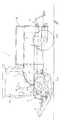
まず、構成から説明すると、1は移動車両の一形態を示す多目的型の運搬車両であって、機体の前後部に夫々前輪2と後輪3を備え、これらは操縦席5の近傍に設けた操舵スイッチ6を操作することによって前輪2のみが操舵できる前輪操舵と、後輪3のみが操舵できる後輪操舵と、前後輪2,3が互いに逆向きに操舵される4WS操舵とに切換えができるようになっている。Embodiments will be described below with reference to the drawings.
First, from the configuration, 1 is a multi-purpose transport vehicle showing one form of a moving vehicle, which includes
機体後部にはエンジン8が搭載され、このエンジン8の回転動力はミッションケース9内に収容されている油圧式無段変速装置(HST)10と高中低速3段に変速可能な副変速装置11とに伝達され、これらの油圧式無段変速装置(HST)10、副変速装置11によって減速された回転動力が前輪2と後輪3に伝達される。副変速装置11は図5に示すようにレバーガイド30に設けられた副変速レバー12を前後方向に操作して切り換える。 An engine 8 is mounted at the rear of the machine body. The rotational power of the engine 8 is a hydraulic continuously variable transmission (HST) 10 housed in a
前記油圧式無段変速装置10は油圧ポンプと油圧モータとからなるユニットを一体構成した周知の構造のものであり、ユニットから左右横方向に突出するトラニオン軸14の回動角を変更することによって油圧式無段変速装置10の斜板の角度を変え、機体の進行方向と速度を変えることができる。油圧式無段変速装置10の操作部の構造については後述する。多目的運搬車両1は機体の前部と後部に夫々昇降装置15,16を備えており、機体前部においては芝刈作業を行うモア18を昇降自在に連結し、機体後部においては道路を清掃するブラシ等を連結することができるようになっている。フロント、リヤに装着される作業機はこれらのモア、ブラシに限定されるものではなく、これら以外の例えば除雪機や簡易型のカルチ等であってもよい。 The hydraulic continuously
この実施例で説明する運搬車両1は操縦席5の周囲がキャビン19で覆われており、その後方には作業機や資材を積み込むことができる荷台20が設けられている。この荷台20は固定式であっても回動であってもよく、回動式の場合は油圧シリンダー等で荷台20部分を上昇させる。 In the
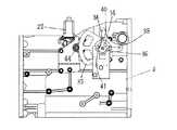
次に図2、図3に基づいて油圧式無段変速装置10の操作部の構成について説明する。
この発明における油圧式無段変速装置10のトラニオン軸14は電動式の正逆転モータ22で駆動される点が特徴であり、このため、前進ペダル23あるいは後進ペダル24を踏み込むとその踏み込み量がポジションセンサ25で検出され、コントローラ27からの指令によって踏込量に応じて正逆転モータ22が駆動される。具体的構成を説明すると、フロア29の右側には前進ペダル23と後進ペダル24が軸33,33を中心に回動自在に支持され、夫々の軸33上には各ペダル23,24の踏込回動角度を検出するアナログ式のポジションセンサ25,25が取り付けられている。前進ペダル23と後進ペダル24は夫々独立して左右に併設する形態でも良いが、ペダル全体を1枚の板で形成した一体型とし、つま先でペダルの前側を踏めば前進、踵でペダルの後側を踏めば後進する形態のもでもよい。また、ポジションセンサ25は1つで前進側と後進側の踏み込み量を検出するものでもよい。Next, the configuration of the operation unit of the hydraulic continuously
The
一方、トラニオン軸14上には扇型状の大径ギヤ35が固着され、更にその外側にトラニオン軸14の回動角度を検出するセンサ36が設けられている。なお、この実施例ではトラニオン軸14の外側に円筒状のボス37を嵌合させ、このボス37をボルト38で締め付けてトラニオン軸14とボス37との一体化を図り、このボス37には水平横向きにピン34を固着する。そして、上記センサ36の回動軸39にアーム40を取り付け、このアーム40にはU字状に形成された長孔41を形成し、この長孔41内にボス37側のピン34を挿入してトラニオン軸14の回動角度を検出するように構成している。 On the other hand, a fan-shaped large-
長孔41内をピン34が相対的に摺動する構成のため、センサ36がピン34に対して直交していなくても回動量の検出に支障を来たすことはない。
また、前記扇型状の大径ギヤ35の前側には小径のピニオンギヤ44が噛み合わされ、このピニオンギヤ44はミッションケース9の左側横にあって縦方向に設けられた正逆転モータ22により駆動されるようにしている。Since the
Further, a small-
このような構成において、前進ペダル23を踏むとその踏み込み量がポジションセンサ25で検出され、その踏み込み量に応じた値の正転出力が正逆転モータ22に対して出力される。そして、トラニオン軸14が正転方向に回動されるとその回動量がトラニオン軸回動センサ36によって検出され、設定された回動角に達した時点で正逆転モータ22に対する制御出力をカットするようにしている。後進の場合も同様であり、後進ペダル24の踏み込み量に応じて正逆転モータ22が逆転方向に駆動され、設定された角度に達すると正逆転モータ22に対する制御出力をカットするようにしている。 In such a configuration, when the
前進、後進、いずれの場合もペダル23,24から足を離せば図示外の中立復帰機構が作動してペダル23,24が中立位置に戻り、トラニオン軸14を中立位置に復帰させ、機体を停止させるようにしている。 In both forward and reverse directions, when the foot is released from the
また、この発明においては、ペダル23,24を踏み込んだ状態でオートクルーズスイッチ50を押せばペダル23,24から足を離してもトラニオン軸14は設定された踏み込み位置を保持する機構が設けられている。この場合において、前進ペダル23と後進ペダル24自体は元の中立位置に戻るようにしている。さらにその状態において、僅かに前進速度、あるいは後進速度を増減速させたいときには、増速スイッチ52と減速スイッチ53を押せばトラニオン軸14が微小角度だけ増速方向、あるいは減速方向に回転する。 In the present invention, if the auto-
図6は制御ブロック図であり、構成を簡単に説明すると、コントローラ27の入力側には、前進ペダル23の踏み込み量を検知する前進用ポジションセンサ25、後進用ペダル24の踏み込み量を検知する後進用ポジションセンサ25、トラニオン軸14の回動量を検出するトラニオン軸14回動センサ36、前進ペダル23で設定された車速を維持するときに押すクルーズコントロールSW50、オートクルーズにより設定された車速を僅かに増減させるときに押す増速SW52と減速SW53がコントローラ27の入力側に接続され、出力側には正逆転モータ22が接続されている。 FIG. 6 is a control block diagram, and the configuration will be briefly described. On the input side of the
このような構成において、オペレータが前進ペダル23を踏み込むと、ペダルの踏み込み量が前進用ポジションセンサ25で検出され、それによってトラニオン軸14が正転(前進)方向に回動させられる。トラニオン軸14の回動量はトラニオン軸14回動センサ36で検出されているので、設定された角度に達すると正逆転モータ22の回転は停止される。通常はこの状態で作業を行うが、定速走行を行うときにはオートクルーズスイッチ50を押す。すると、その時点で正逆転モータ22に対する制御指令がカットされるため、モータ22はその位置で停止することになり、前進ペダル23は中立位置に復帰するものの、トラニオン軸14は設定された位置に止まって機体の前進速度は一定に保たれることになる。 In such a configuration, when the operator depresses the
そして、作業中に作業機側の負荷が大きくなって車速を僅かに下げたいときには、減速スイッチ53を押す。減速スイッチ53を押すとトラニオン軸14は逆転(後進)方向に戻され、機体の走行速度はそれまでの設定車速に対して僅かに減速させられる。 Then, when the load on the work machine side increases during work and it is desired to slightly reduce the vehicle speed, the
反対に機体の車速を増速したいときには増速スイッチ52を押す。この場合は先の場合と逆にトラニオン軸14は正転(前進)方向に回動されて車速は増速される。
このように、この実施例においては、完全なフィードバック制御ではないものの、オペレータが意識的に車速の増減速を図りたいときだけ増速スイッチ52か減速スイッチ53を押して車速を微少に調節できるものであるから、応答速度が速いだけでなく、構成も簡潔な分、廉価に構成できる特徴を有する。On the contrary, when it is desired to increase the vehicle speed of the fuselage, the
As described above, in this embodiment, although the feedback control is not complete, the vehicle speed can be slightly adjusted by pressing the
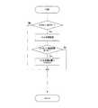
図7のフローチャートは増減速スイッチ52,53自体を廃止し、前進ペダル23と後進ペダル24でその機能を持たせるようにしたものである。
即ち、前進ペダル23の踏み込み中にオートクルーズスイッチ50を押して正逆転モータ22に対する制御出力をカットし、その前進速度を固定する点は前述の場合と同じであるが、この場合においては前進ペダル23が増速スイッチ52として、後進ペダル24が減速スイッチ53として機能するようにした点が異なっている。In the flowchart of FIG. 7, the acceleration / deceleration switches 52 and 53 themselves are eliminated, and the
That is, while the
オートクルーズを設定して前進走行しているときに前進ペダル23を踏むと車速が僅かに増速されてそれが新たな前進車速になり、逆に後進ペダル24を踏むと速度が減速されるようになっている。なお、この実施例においては、元々運搬車に備えられている前進ペダル23と後進ペダル24とを利用してこれらの踏み込みによってオートクルーズで設定した車速を微小に増減速させる構成としたので、余分なスイッチが不要になるというメリットがあると共に、全て足で操作できるので、瞬時に増減速調節に対応できるという特徴が存する。図8も図7の場合と同様の構成であり、オートクルーズの設定中に前進ペダル23又は後進ペダル24を踏み込み、その踏み込み時間が所定時間(この例では1秒)以上であれば設定された車速に対して略1km/h分だけ速度を上昇させ、後進ペダル24を踏むと逆に略1km/h分だけ速度を下げるように構成している。 When the
なお、一度設定された車速はブレーキペダル55を踏むか、クラッチペダル56を踏むか、副変速操作レバー12を高速側に切り換えたときに解除するように電気的にあるいは機械的に連動構成すればよく、そのように構成することによってオペレータがオートクルーズが作動していることを忘れてしまって事故を招いてしまうといった危険を回避することができるものである。 The vehicle speed once set may be electrically or mechanically linked so as to be released when the
また、オートクルーズスイッチ50とは別に前回の設定を有効とする記憶スイッチ(図示省略)を設けてもよく、この記憶スイッチを設けることによって、オートクルーズ設定中に前回使用していた車速を再び選択することができる。図9のフローチャートはその流れを説明したものであり、記憶スイッチを押すことによって前回固定維持していたトラニオン軸14の位置に正逆転モータ22が駆動され、その位置に固定されるので、例えば、オートクルーズを用いた芝刈作業を中断し、再び作業を開始するようなときには便利である。作業中断の前後で作業速度は変わらないので、刈跡が変わるといった問題を生じることがない。 In addition to the
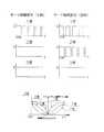
最後に図10、図11に示すペダルの戻りに関する改良機構について説明する。
一般に前進ペダル23あるいは後進ペダル24から足を離すと油圧式無段変速装置10に具備された中立復帰用機構が作動してペダル23,24が急激に中立位置(停止位置)に戻ることになるが、この戻り方は副変速装置11の変速位置によって大きく変わる。Finally, an improved mechanism for returning the pedal shown in FIGS. 10 and 11 will be described.
Generally, when the foot is released from the
比較的高速で走行している3速の状態よりも、減速比が大きい1速、2速のときの方がその戻りが急激となり勝ちである。そこで、この不具合を解消する機構として、減速比が大きいとき程、車速を減速させる、即ち、正逆転モータ22に対する逆転出力を遅くするようにしている。 The first and second gears with a large reduction ratio are more rapid than the third gear running at a relatively high speed, and the return is quicker. Therefore, as a mechanism for solving this problem, the vehicle speed is reduced as the reduction ratio is larger, that is, the reverse rotation output to the forward /
図10に示すように、3速の連続波形に対して2速、1速はパルス波形とし、2速の場合よりも1速のパルス幅をさらに細かくした点が特徴であり、高速で走行している副変速の3速時の減速は、一気に減速させても惰性で走行できる分だけショックが少なく、2速、1速の場合には減速を一気に行うとオペレータは前方につんのめるような感じになるので、正逆転モータ22による逆転出力を遅く出すようにしている。前進ペダル23から足を離したときに減速が徐々に行われるから機体が急激に停止するような危険性はなく、滑らかな減速が行われ燃費も向上する。 As shown in FIG. 10, the second speed and the first speed are pulse waveforms with respect to the continuous speed of the third speed, and the pulse width of the first speed is made finer than that of the second speed. The speed reduction at the 3rd speed of the sub-shift is less shocking as long as the vehicle can run by inertia even if it is decelerated at once, and in the case of 2nd speed and 1st speed, the operator feels like picking forward. Therefore, the reverse rotation output by the forward /
図11は発進時と後進時にパルスの幅を変更して制御する例を示したものである。発進時で副変速装置が1速の場合にはパルス制御によって正逆転モータ22を正転させる構造とし、2速、3速では連続出力でモータを回転させる。後進時は1速、2速ともパルス制御とし、3速のみ連続出力とした。このように制御することによって前進時も後進時も滑らかに発進でき減速する際のショックも軽減される。 FIG. 11 shows an example in which control is performed by changing the pulse width at the time of start and reverse. When the sub-transmission device is at the first speed at the start, the forward /
1 運搬車
2 前輪
3 後輪
5 操縦席
8 エンジン
9 ミッションケース
10 油圧式無段変速装置
14 トラニオン軸
22 正逆転モータ
23 前進ペダル
24 後進ペダル
25 ポジションセンサ
27 コントローラ
36 トラニオン軸回動センサ
50 オートクルーズスイッチ
52 増速スイッチ
53 減速スイッチDESCRIPTION OF
Claims (4)
Translated fromJapanesePriority Applications (1)
| Application Number | Priority Date | Filing Date | Title |
|---|---|---|---|
| JP2004315153AJP2006125535A (en) | 2004-10-29 | 2004-10-29 | Auto cruise device for moving vehicles |
Applications Claiming Priority (1)
| Application Number | Priority Date | Filing Date | Title |
|---|---|---|---|
| JP2004315153AJP2006125535A (en) | 2004-10-29 | 2004-10-29 | Auto cruise device for moving vehicles |
Publications (1)
| Publication Number | Publication Date |
|---|---|
| JP2006125535Atrue JP2006125535A (en) | 2006-05-18 |
Family
ID=36720467
Family Applications (1)
| Application Number | Title | Priority Date | Filing Date |
|---|---|---|---|
| JP2004315153APendingJP2006125535A (en) | 2004-10-29 | 2004-10-29 | Auto cruise device for moving vehicles |
Country Status (1)
| Country | Link |
|---|---|
| JP (1) | JP2006125535A (en) |
Cited By (10)
| Publication number | Priority date | Publication date | Assignee | Title |
|---|---|---|---|---|
| JP2009180232A (en)* | 2008-01-29 | 2009-08-13 | Iseki & Co Ltd | Continuously variable work vehicle |
| JP2011505527A (en)* | 2007-11-30 | 2011-02-24 | キャタピラー インコーポレイテッド | Dynamic controller for continuously variable transmission |
| JP2011064275A (en)* | 2009-09-17 | 2011-03-31 | Yanmar Co Ltd | Riding type farm working machine |
| JP2016008655A (en)* | 2014-06-24 | 2016-01-18 | 井関農機株式会社 | Work vehicle |
| JP2016098985A (en)* | 2014-11-26 | 2016-05-30 | 井関農機株式会社 | Work vehicle |
| EP2551557A3 (en)* | 2011-07-29 | 2018-01-10 | Kubota Corporation | Speed change control system for a vehicle |
| CN108674181A (en)* | 2018-07-23 | 2018-10-19 | 安徽省锦瑞汽车部件有限公司 | A kind of electronic pedal structure |
| CN109703690A (en)* | 2019-01-15 | 2019-05-03 | 东北大学 | A multi-purpose continuously variable transmission that can be controlled manually or automatically |
| US10280595B2 (en) | 2014-03-03 | 2019-05-07 | Cnh Industrial America Llc | Compact wheel loader |
| JP2020065469A (en)* | 2018-10-23 | 2020-04-30 | 株式会社クボタ | Mower |
Citations (3)
| Publication number | Priority date | Publication date | Assignee | Title |
|---|---|---|---|---|
| JPH0725265A (en)* | 1993-07-12 | 1995-01-27 | Jidosha Denki Kogyo Co Ltd | Automatic constan speed traveling device |
| JPH07132756A (en)* | 1993-11-05 | 1995-05-23 | Fujitsu Ten Ltd | Constant speed running device |
| JP2004017912A (en)* | 2002-06-20 | 2004-01-22 | Yanmar Agricult Equip Co Ltd | Work vehicle |
- 2004
- 2004-10-29JPJP2004315153Apatent/JP2006125535A/enactivePending
Patent Citations (3)
| Publication number | Priority date | Publication date | Assignee | Title |
|---|---|---|---|---|
| JPH0725265A (en)* | 1993-07-12 | 1995-01-27 | Jidosha Denki Kogyo Co Ltd | Automatic constan speed traveling device |
| JPH07132756A (en)* | 1993-11-05 | 1995-05-23 | Fujitsu Ten Ltd | Constant speed running device |
| JP2004017912A (en)* | 2002-06-20 | 2004-01-22 | Yanmar Agricult Equip Co Ltd | Work vehicle |
Cited By (13)
| Publication number | Priority date | Publication date | Assignee | Title |
|---|---|---|---|---|
| JP2011505527A (en)* | 2007-11-30 | 2011-02-24 | キャタピラー インコーポレイテッド | Dynamic controller for continuously variable transmission |
| JP2009180232A (en)* | 2008-01-29 | 2009-08-13 | Iseki & Co Ltd | Continuously variable work vehicle |
| JP2011064275A (en)* | 2009-09-17 | 2011-03-31 | Yanmar Co Ltd | Riding type farm working machine |
| EP2551557A3 (en)* | 2011-07-29 | 2018-01-10 | Kubota Corporation | Speed change control system for a vehicle |
| US10280595B2 (en) | 2014-03-03 | 2019-05-07 | Cnh Industrial America Llc | Compact wheel loader |
| JP2016008655A (en)* | 2014-06-24 | 2016-01-18 | 井関農機株式会社 | Work vehicle |
| JP2016098985A (en)* | 2014-11-26 | 2016-05-30 | 井関農機株式会社 | Work vehicle |
| CN108674181A (en)* | 2018-07-23 | 2018-10-19 | 安徽省锦瑞汽车部件有限公司 | A kind of electronic pedal structure |
| CN108674181B (en)* | 2018-07-23 | 2024-01-26 | 安徽省锦瑞汽车部件有限公司 | Electronic pedal structure |
| JP2020065469A (en)* | 2018-10-23 | 2020-04-30 | 株式会社クボタ | Mower |
| JP7065747B2 (en) | 2018-10-23 | 2022-05-12 | 株式会社クボタ | Mower |
| CN109703690A (en)* | 2019-01-15 | 2019-05-03 | 东北大学 | A multi-purpose continuously variable transmission that can be controlled manually or automatically |
| CN109703690B (en)* | 2019-01-15 | 2020-04-28 | 东北大学 | Multipurpose stepless speed changer capable of being manually or automatically controlled |
Similar Documents
| Publication | Publication Date | Title |
|---|---|---|
| CN106184210B (en) | Working truck | |
| KR101716724B1 (en) | Riding-type rice transplanter | |
| WO2001056864A1 (en) | Hydraulically driven traveling vehicle | |
| KR20100125250A (en) | Traveling agricultural machine | |
| JP2006125535A (en) | Auto cruise device for moving vehicles | |
| JP6548609B2 (en) | Work vehicle | |
| JP4653725B2 (en) | Work vehicle | |
| JP5858029B2 (en) | Tractor | |
| JP2013170609A (en) | Working vehicle | |
| JP2005119466A (en) | Travel transmission for work vehicle | |
| JP2007230304A (en) | Auto cruise device for HST tractor | |
| JP5958363B2 (en) | Traveling vehicle | |
| JP6090068B2 (en) | Work vehicle | |
| JP2009083612A (en) | Work vehicle | |
| JP4479325B2 (en) | PTO control device for tractor | |
| JP4796432B2 (en) | Work vehicle travel stop control device | |
| JP2009132309A (en) | Work vehicle | |
| JP5742688B2 (en) | Work vehicle | |
| JP3497411B2 (en) | Travel shifting structure of paddy field vehicle | |
| JP2021107689A (en) | Work vehicle | |
| JP2007245861A (en) | Forward / reverse switching control device for work vehicle | |
| JP2015101163A (en) | Work vehicle | |
| JP2003185006A (en) | Work vehicle shift control device | |
| JP6484977B2 (en) | Work vehicle | |
| JP2010053925A (en) | Work vehicle |
Legal Events
| Date | Code | Title | Description |
|---|---|---|---|
| A621 | Written request for application examination | Free format text:JAPANESE INTERMEDIATE CODE: A621 Effective date:20071029 | |
| A977 | Report on retrieval | Free format text:JAPANESE INTERMEDIATE CODE: A971007 Effective date:20100128 | |
| A131 | Notification of reasons for refusal | Free format text:JAPANESE INTERMEDIATE CODE: A131 Effective date:20100216 | |
| A521 | Written amendment | Free format text:JAPANESE INTERMEDIATE CODE: A523 Effective date:20100416 | |
| A02 | Decision of refusal | Free format text:JAPANESE INTERMEDIATE CODE: A02 Effective date:20100824 |