JP2006119941A - Moving image storage method - Google Patents
Moving image storage methodDownload PDFInfo
- Publication number
- JP2006119941A JP2006119941AJP2004307584AJP2004307584AJP2006119941AJP 2006119941 AJP2006119941 AJP 2006119941AJP 2004307584 AJP2004307584 AJP 2004307584AJP 2004307584 AJP2004307584 AJP 2004307584AJP 2006119941 AJP2006119941 AJP 2006119941A
- Authority
- JP
- Japan
- Prior art keywords
- image
- storage
- control
- data
- request
- Prior art date
- Legal status (The legal status is an assumption and is not a legal conclusion. Google has not performed a legal analysis and makes no representation as to the accuracy of the status listed.)
- Pending
Links
Images


Classifications
- H—ELECTRICITY
- H04—ELECTRIC COMMUNICATION TECHNIQUE
- H04N—PICTORIAL COMMUNICATION, e.g. TELEVISION
- H04N21/00—Selective content distribution, e.g. interactive television or video on demand [VOD]
- H04N21/40—Client devices specifically adapted for the reception of or interaction with content, e.g. set-top-box [STB]; Operations thereof
- H04N21/43—Processing of content or additional data, e.g. demultiplexing additional data from a digital video stream; Elementary client operations, e.g. monitoring of home network or synchronising decoder's clock; Client middleware
- H04N21/436—Interfacing a local distribution network, e.g. communicating with another STB or one or more peripheral devices inside the home
- H04N21/43615—Interfacing a Home Network, e.g. for connecting the client to a plurality of peripherals
- H—ELECTRICITY
- H04—ELECTRIC COMMUNICATION TECHNIQUE
- H04L—TRANSMISSION OF DIGITAL INFORMATION, e.g. TELEGRAPHIC COMMUNICATION
- H04L67/00—Network arrangements or protocols for supporting network services or applications
- H04L67/01—Protocols
- H04L67/10—Protocols in which an application is distributed across nodes in the network
- H04L67/1001—Protocols in which an application is distributed across nodes in the network for accessing one among a plurality of replicated servers
- H04L67/1004—Server selection for load balancing
- H04L67/1017—Server selection for load balancing based on a round robin mechanism
- H—ELECTRICITY
- H04—ELECTRIC COMMUNICATION TECHNIQUE
- H04L—TRANSMISSION OF DIGITAL INFORMATION, e.g. TELEGRAPHIC COMMUNICATION
- H04L12/00—Data switching networks
- H04L12/28—Data switching networks characterised by path configuration, e.g. LAN [Local Area Networks] or WAN [Wide Area Networks]
- H04L12/2803—Home automation networks
- H04L12/2838—Distribution of signals within a home automation network, e.g. involving splitting/multiplexing signals to/from different paths
- H—ELECTRICITY
- H04—ELECTRIC COMMUNICATION TECHNIQUE
- H04L—TRANSMISSION OF DIGITAL INFORMATION, e.g. TELEGRAPHIC COMMUNICATION
- H04L12/00—Data switching networks
- H04L12/28—Data switching networks characterised by path configuration, e.g. LAN [Local Area Networks] or WAN [Wide Area Networks]
- H04L12/2803—Home automation networks
- H04L2012/2847—Home automation networks characterised by the type of home appliance used
- H04L2012/2849—Audio/video appliances
Landscapes
- Engineering & Computer Science (AREA)
- Signal Processing (AREA)
- Computer Networks & Wireless Communication (AREA)
- Multimedia (AREA)
- Two-Way Televisions, Distribution Of Moving Picture Or The Like (AREA)
- Information Transfer Between Computers (AREA)
- Information Retrieval, Db Structures And Fs Structures Therefor (AREA)
- Closed-Circuit Television Systems (AREA)
Abstract
Translated fromJapaneseDescription
Translated fromJapanese画像を蓄積する技術に関する。 The present invention relates to a technique for accumulating images.
近年、監視映像やライブ映像等の動画コンテンツ蓄積は、アナログ方式に比べて画質劣化がない等の優れた特徴をもつデジタル形式での蓄積へと移行しつつある。こうした背景の中、ネットワーク接続したストレージ装置(以下、画像蓄積装置と称する)に画像を蓄積する技術への関心が高まっている。動画像の蓄積技術は、室内監視のような小規模なものから都市監視や河川監視など広域を監視する大規模なものまで様々な需要がある。 In recent years, the accumulation of moving image content such as surveillance video and live video is shifting to the digital format having superior characteristics such as no deterioration in image quality compared to the analog method. Against this background, interest in technology for storing images in a storage device connected to a network (hereinafter referred to as an image storage device) is increasing. There is a variety of demands for moving image storage technology, from a small one such as indoor monitoring to a large one that monitors a wide area such as city monitoring and river monitoring.
ここで、複数の画像入力装置(監視カメラ等)から送出される動画データを受信して蓄積する画像蓄積装置がある。この既存技術は、画像入力装置が画像蓄積装置に対し制御データである蓄積要求を送出し、当該要求に対する画像蓄積装置からの応答に応じて画像入力装置が動画データを送出することを特徴とする。しかし、1台の画像蓄積装置に同時蓄積できる画像量には画像蓄積装置性能面での限界があるため、画像入力装置の台数の増加に伴い、複数の画像蓄積装置に分散して動画データを蓄積するための蓄積先選択装置(負荷分散装置)が使用されている。 Here, there is an image storage device that receives and stores moving image data transmitted from a plurality of image input devices (such as monitoring cameras). This existing technology is characterized in that the image input device sends a storage request as control data to the image storage device, and the image input device sends moving image data in response to a response from the image storage device to the request. . However, since the amount of images that can be stored simultaneously in one image storage device is limited in terms of image storage device performance, as the number of image input devices increases, moving image data is distributed to a plurality of image storage devices. A storage destination selection device (load distribution device) for storage is used.
一般に、蓄積先選択装置及び画像蓄積装置は監視センタなどに設置され、画像入力装置は監視対象エリア全体に広域に設置される。防犯を目的とした監視システムなどでは画像蓄積装置を保護する必要があるため、ファイアウォールと呼ばれる保護装置も使用されている。監視センタにファイアウォール装置を置くことにより、監視妨害を目的とした不正アクセスから蓄積先選択装置及び画像蓄積装置を保護することができる。以下、既存の負荷分散技術について述べ、次に既存の保護技術について述べる。 In general, the storage destination selection device and the image storage device are installed in a monitoring center or the like, and the image input device is installed over the entire monitoring target area. Since it is necessary to protect the image storage device in a surveillance system for the purpose of crime prevention, a protection device called a firewall is also used. By placing a firewall device in the monitoring center, the storage destination selection device and the image storage device can be protected from unauthorized access for the purpose of monitoring interference. The following describes the existing load balancing technology, and then describes the existing protection technology.
既存の負荷分散技術として、例えば、DNSラウンドロビンを用いた方式では、予めドメイン名に対応するIPアドレスをDNSサーバに複数登録しておき、DNSサーバへIPアドレス問い合わせがある毎に順次異なるIPアドレスを返信する(非特許文献1参照)。これにより、同一ドメインへのアクセスを異なるアクセス先に分散することができる。即ち、DNSサーバが蓄積先選択装置に相当し、DNSサーバにより提供されたIPアドレスが割り当てられた画像蓄積装置の宛先に対応する。また、画像蓄積装置の空き容量などといった情報を用いて、DNSラウンドロビンより高度に画像蓄積装置を選択している方式もある(特許文献1参照)。 As an existing load balancing technology, for example, in the method using DNS round robin, multiple IP addresses corresponding to domain names are registered in advance in the DNS server, and each time an IP address inquiry is made to the DNS server, the IP address is sequentially changed. Is returned (see Non-Patent Document 1). Thereby, access to the same domain can be distributed to different access destinations. That is, the DNS server corresponds to the storage destination selection device, and corresponds to the destination of the image storage device to which the IP address provided by the DNS server is assigned. There is also a method in which an image storage device is selected more highly than DNS round robin using information such as the free space of the image storage device (see Patent Document 1).
次に、既存の保護技術として、ファイアウォールがある。ファイアウォールは保護対象ネットワークを外部ネットワークからの不正アクセスから保護するための装置である。保護方式には、保護対象ネットワークの内部から外部へのアクセスのみ許可し、外部から内部へのアクセスを全て禁止するといった比較的単純な処理のものから、パケットを暗号化したりヘッダ内容の検査を行うなど複雑な処理のものまで、様々な方式がある。画像蓄積では大量のデータを送受するので、ファイアウォールにも高い性能(スループット)が求められる。このため、複雑なセキュリティ方式では高速なプロセッサを搭載する必要がありファイアウォール構築コストが高くなるという問題がある。 Next, there is a firewall as an existing protection technology. A firewall is a device for protecting a protection target network from unauthorized access from an external network. The protection method uses only relatively simple processing such as permitting only access from the inside to the outside of the protected network and prohibiting all access from the outside to the inside, and performs packet encryption and header content inspection. There are various methods up to complicated processing. In image storage, a large amount of data is transmitted and received, so high performance (throughput) is also required for the firewall. For this reason, in a complicated security method, it is necessary to install a high-speed processor, and there is a problem that the cost for constructing a firewall becomes high.
ここで、安価に高セキュリティかつ高スループットのファイアウォールを構築する方法に、PULL型アクセスがある。PULL型アクセスではファイアウォール外部から内部へのアクセス禁止する。そして、HTTPといったプロトコルを用いて内部から外部へのアクセスの応答として外部のデータを取得する(非特許文献1参照)。これは、ファイアウォールを越えるための一般的な手法でもある(特許文献2参照)。 Here, PULL type access is a method for constructing a firewall with high security and high throughput at low cost. In PULL type access, access from outside to inside of the firewall is prohibited. Then, external data is acquired as a response to access from the inside to the outside using a protocol such as HTTP (see Non-Patent Document 1). This is also a general method for crossing a firewall (see Patent Document 2).
これに対して、ファイアウォールを介して、直接外部から内部へデータを送る場合はPUSH型アクセスと呼ばれる。PUSH型アクセスを実現するためには、あらかじめファイアウォールに特定のPUSH型アクセスのみ通過できる穴をあける設定を行う必要がある。この穴がセキュリティホールとなってしまう可能性があるため、必要なときだけ穴をあけて普段は閉じておく、認証機能を併用する、などの対策が必要となる。即ち、PULL型のみの場合と比較すると、PUSH型では高いセキュリティを保つためにコスト高になる傾向にある。 On the other hand, when data is sent directly from outside to inside through a firewall, it is called PUSH type access. In order to realize PUSH type access, it is necessary to make a setting to make a hole that allows only specific PUSH type access through the firewall in advance. Since this hole may become a security hole, it is necessary to take measures such as making a hole only when necessary and closing it normally, or using an authentication function together. That is, compared with the case of only the PULL type, the PUSH type tends to be expensive in order to maintain high security.
上記従来技術では、最終的に画像入力装置が画像蓄積装置に対し蓄積要求(制御データ)を行い、それと同じ経路で画像を画像蓄積装置に送出している。そのため、安価に画像蓄積装置を保護できるPULL方式を用いることができないので画像蓄積装置の保護に必要なコストが高い。更に、システム規模が大規模になるほど画像蓄積装置台数も多くなり、画像蓄積装置毎に備える必要のある保護装置台数も多くなるため設備コスト増大の要因となっている。 In the above prior art, the image input device finally makes a storage request (control data) to the image storage device, and sends the image to the image storage device through the same route. Therefore, since the PULL system that can protect the image storage device at low cost cannot be used, the cost required for protecting the image storage device is high. Furthermore, the larger the system scale, the greater the number of image storage devices, and the greater the number of protection devices that need to be provided for each image storage device, which increases the facility cost.
本発明の目的は、この問題を解決してスケーラブルかつセキュアな動画像蓄積システムを低コストで実現することである。 An object of the present invention is to solve this problem and realize a scalable and secure moving image storage system at low cost.
蓄積要求などの制御データと画像データを異なる経路で画像蓄積装置に送出する。即ち、画像入力装置から送出された制御データは蓄積先選択装置を介して画像蓄積装置に送出し、画像データは画像入力装置が直接、画像蓄積装置へ送出する。 Control data such as a storage request and image data are sent to the image storage device through different paths. That is, the control data sent from the image input device is sent to the image storage device via the storage destination selection device, and the image data is sent directly to the image storage device by the image input device.
本発明によれば、制御データと動画データの送出経路を分離することによりデータ種類に応じて異なる保護方法で画像蓄積装置を保護することができる。従って、データ量の少ない制御データを集中的にチェックすることができ、高いセキュリティレベルの実現と画像蓄積装置保護に伴うコストの削減を両立することが可能となる。 According to the present invention, the image storage apparatus can be protected by a different protection method depending on the data type by separating the control data and moving image data transmission paths. Therefore, control data with a small amount of data can be intensively checked, and it is possible to achieve both a high security level and a reduction in costs associated with image storage device protection.
以下に、本発明の実施の形態を説明する。 Hereinafter, embodiments of the present invention will be described.
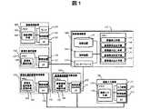
図1は、本発明のシステム構成を示す。システムは複数の画像入力装置101、蓄積先選択装置102、画像蓄積装置103、画像視聴装置106、画像蓄積装置103を保護する画像蓄積装置保護装置104、及び、蓄積先選択装置102を保護する蓄積先選択装置保護装置105とからなる。 FIG. 1 shows a system configuration of the present invention. The system includes a plurality of
画像蓄積装置保護装置104及び蓄積先選択装置保護装置105はファイアウォールと称される装置である。画像視聴装置106は画像を表示するためのモニタを備えた端末装置である。例えば、ビル監視システムにおいては、蓄積先選択装置102、画像蓄積装置103、画像視聴装置106、及び、保護装置104、105は、監視室に設置され、画像入力装置101は監視対象エリアであるビル内の各フロアに設置される。 The image storage
画像入力装置101は、インターフェース171、制御装置172、入力装置173、及び、メモリ174とからなる。メモリ173は、画像入力手順プログラム175を格納する。画像入力装置101では、制御装置172が、入力装置173から入力された動画像を、画像入力手順プログラム175を実行することによりパケット化し、インターフェース171を介してネットワークへ送出する。 The
蓄積先選択装置102は、インターフェース121、制御装置122、及び、メモリ123とからなる。メモリ123は、蓄積先選択手順プログラム124を格納する。制御装置122は、蓄積先選択手順プログラム124を実行することにより、インターフェース121を介して画像入力装置101より送出される蓄積要求を受信し、画像蓄積装置を選択し、選択した画像蓄積装置へ蓄積要求を転送する。 The storage
画像蓄積装置103は、記憶装置112、メモリ113、制御装置114、及び、インターフェース115とからなる。メモリ113は、障害検出手順プログラム107、蓄積要求送出手順プログラム108、画像読み出し手順プログラム109、蓄積要求判定手順プログラム110、及び、画像書き込み手順プログラム111を格納する。制御装置114は、蓄積要求判定手順プログラム110を実行することにより、インターフェース115を介して受信した蓄積要求を受理可能か判定し、画像書き込み手順プログラム111を実行することにより、動画データを記憶装置112へ蓄積する。同様に障害検出手順プログラム102を実行することにより、記憶装置112の障害を検出し、蓄積要求送出手順プログラム108を実行することにより、インターフェース115を介して他の画像蓄積装置へ代理蓄積を要求する。また、画像読み出し手順プログラム109を実行することにより、記憶装置112に格納された動画を画像視聴装置106へ送出する。 The
画像蓄積装置保護装置104は、インターフェース141、制御装置142、及び、メモリ143とからなる。メモリ143は、画像蓄積装置保護手順プログラム144を格納する。制御装置142は、画像蓄積装置保護手順プログラム144を実行することにより、インターフェース141を介して受信したパケットをチェックする。当該装置はデータ量の多い動画データを中継するため、高いスループットが要求される。画像入力装置側からのアクセスを完全に禁止することで、画像蓄積装置保護に要する処理を最小限に抑えることができる。 The image storage
蓄積先選択装置保護装置105は、インターフェース151、制御装置152、及び、メモリ153とからなる。メモリ153は、蓄積選択装置保護手順プログラム154を格納する。制御装置152は、蓄積選択装置保護手順プログラム154を実行することにより、インターフェース151を介して受信したパケットをチェックする。当該装置はデータ量の少ない制御データを中継するため、様々な複雑な保護処理を実行することができる。複雑な処理の例として、SSLやTLSやIPsecのようなパケットの暗号化がある。また、少数のサーバに認証処理等を集約することができるため、パスワード管理などの管理コストの削減も期待できる。 The storage destination selection
画像視聴装置106は、インターフェース161、制御装置162、モニタ165、及び、メモリ163とからなる。メモリ163は、画像視聴手順プログラム164を格納する。制御装置162は、画像視聴手順プログラム164を実行することにより、インターフェース161を介して受信した動画データをモニタ165に表示する。 The image viewing device 106 includes an
次に、図2に従って、画像入力装置101により生成される画像が画像蓄積装置103内の記憶装置112に格納されるまでのプロセス(ステップ201〜204)と、格納した画像を視聴するプロセス(ステップ205、206)を示す。本図は、画像入力装置101、蓄積先選択装置保護装置105、蓄積先選択装置102、画像視聴装置106、画像蓄積装置保護装置104、画像蓄積装置103間の通信の流れを示しており、縦軸は上から下へ時間の流れを示す。横軸は装置間で矢印の示す方向へデータが送出されたことを示す。 Next, referring to FIG. 2, a process until the image generated by the
まず、画像入力装置101より蓄積先選択装置102へ蓄積すべき画像があることが通知される(ステップ201)。次に、蓄積先選択装置102が、選択した一つの画像蓄積装置103に画像蓄積要求を送出する。画像蓄積装置の選択手順(アルゴリズム)については後述する。 First, the
尚、ステップ201では、蓄積先選択装置102から画像入力装置101へ蓄積すべき画像があるか問い合わせる方法もある。この場合、ユーザ等が事前に画像入力装置101のアドレス一覧を蓄積先選択装置102のメモリ123に登録しておかなければならない。 In
画像蓄積要求に対し、画像蓄積装置103の制御装置114は、書き込み中の動画の総ビットレート、読み出し中の動画の総ビットレート、及び、記憶装置112の残り容量といった情報に基づき、蓄積要求判定手順プログラム110を実行することにより、当該要求を受理可能か否か判断し、判断結果を蓄積先選択装置102へ応答する(ステップ202)。 In response to the image storage request, the
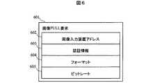
要求が受理されなかった場合、蓄積先選択装置102は後述のアルゴリズムに従い他の画像蓄積装置103へ画像蓄積要求を送出する。要求が受理された場合は、画像蓄積装置103から画像入力装置101へ画像PULL要求が送出される(ステップ203)。そして、その応答として画像入力装置101から画像データを得る(ステップ204)。当該画像データは画像のプロトコルやフォーマット(コーデック)毎に異なる画像書き込み手順プログラム111が実行されることにより、記憶装置112へ格納される。 If the request is not accepted, the storage
上述の、画像PULL要求の詳細を図6に示す。画像PULL要求601は、画像入力装置アドレス602、認証情報603、フォーマット604、ビットレート605などの情報からなる。画像入力装置101が複数のフォーマットやビットレートに対応する場合、制御装置114は、画像のフォーマット604、ビットレート605の値を参考に1つを選択する。また、画像入力装置101から先だって送出される画像蓄積要求中にランダムに生成したパスワードを埋め込み、このパスワードを認証情報603として埋め込むことで、蓄積要求を送出した相手がPULLしていることを確認することができる。 Details of the image pull request described above are shown in FIG. The
PULL方式では画像蓄積装置103から画像入力装置101へアクセスが行われるため、画像入力装置101から画像蓄積装置103へアクセスするPUSH型のように、動画転送性能を兼ね備えた認証機能を画像蓄積装置毎に具備する必要はない。 In the PULL system, since the
ステップ201における画像入力装置101と蓄積先選択装置102間の通信は蓄積先選択装置保護装置105を介して行われ、ステップ203及びステップ204の通信は画像蓄積装置保護装置104を介して行われる。保護装置104はデータ量の多い画像データを送受するので処理性能の低下を避けるために、外部からのアクセスを全て遮断するなどの単純なフィルタ処理を行う。 Communication between the
一方、保護装置105ではデータ量の少ない制御データしか送受しないため、暗号化、認証機能、複雑なフィルタ処理などを実行できる。即ち、制御データと画像データの通信経路を分割することにより、高価な高スループットかつ複雑な認証・フィルタ処理を実行できるファイアウォールを設置する必要はない。 On the other hand, since the
続いて、蓄積した画像を視聴するプロセスについて述べる。画像の視聴には画像視聴装置106を用いる。視聴したい画像の格納先を蓄積先選択装置102に問い合わせた後(ステップ205)、画像蓄積装置103へ画像要求を行う(ステップ206)。画像要求により視聴する画像が特定できると画像蓄積装置103から画像視聴装置106に動画データが送出される。 Next, a process for viewing the stored image will be described. The image viewing device 106 is used for viewing the image. After inquiring the storage
画像要求の内容を図7に示す。画像要求701は、画像入力装置名702、画像ファイル名703、記録開始・終了時刻704、フォーマット705、ビットレート706などの情報からなる。画像要求への応答内容のフォーマットも、図7と同様である。 The contents of the image request are shown in FIG. The
最初の画像要求に対して合致する画像が一つの場合、当該画像情報の記された画像要求応答と動画データが画像視聴装置106に送出される。複数の画像が合致した場合は、そのリストが画像視聴装置106に送出される。画像視聴装置106のモニタ165上に上記リストを表示し、視聴者がリスト中から1つを選択することにより、次の画像要求で動画を特定し視聴することができる。 When there is one image that matches the first image request, the image request response and the moving image data in which the image information is described are sent to the image viewing device 106. If a plurality of images match, the list is sent to the image viewing device 106. The list is displayed on the
ただし、最初の画像要求で指定した条件が広く、非常に多くの画像が合致するような場合には、リストアップを途中で打ち切り過剰な負荷が蓄積先選択装置102にかかるのを防いでもよい。 However, when the conditions specified in the first image request are wide and a very large number of images are matched, the list-up may be interrupted and an excessive load applied to the storage
蓄積先選択装置102におけるリスト(画像要求応答)作成手順については後述する。 A procedure for creating a list (image request response) in the storage
次に、記憶装置112に障害が発生した場合の処理手順について説明する。制御装置114は、障害検出装置プログラム107を実行しており、例えば、記憶装置112を構成するディスクユニットのうち1つが破損した場合などに、障害を検出する。RAID5などを用いた冗長構成になっていた場合であっても、この状況で更にディスクユニットが破損すると画像データを失ってしまうため、ディスクへの負担を軽減するために現在実行中の蓄積処理を他の画像蓄積装置103に割り当てることが望ましい。 Next, a processing procedure when a failure occurs in the storage device 112 will be described. The
図3に従い、再割り当ての一連のプロセスを説明する。本図は、画像入力装置101、画像蓄積装置保護装置104、蓄積先選択装置102、画像蓄積装置1(103)、画像蓄積装置2(305)間の通信の流れを示しており、縦軸は上から下へ各装置の時間の流れを示す。横軸は装置間で矢印の示す方向へデータが送出されたことを示す。 A series of reallocation processes will be described with reference to FIG. This figure shows the flow of communication among the
まず、障害の発生した画像蓄積装置1(103)から他の画像蓄積装置2(305)に画像蓄積要求が送出される。この要求が受理されるまで後述のアルゴリズムに従い画像蓄積装置を探す(ステップ301)。要求が受理されたら蓄積先選択装置102に通知する(ステップ302)。この通知により、後述の蓄積先割り当て状況テーブルを更新することができる。画像蓄積装置2は画像入力装置101より画像を取得する(ステップ303、304)。 First, an image storage request is sent from the failed image storage device 1 (103) to another image storage device 2 (305). Until this request is accepted, an image storage device is searched according to an algorithm described later (step 301). When the request is accepted, the storage
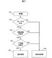
次に、先に述べた蓄積先選択アルゴリズムについて、図4を用いて説明する。電源ON時(ステップ401)に、画像蓄積装置103の制御装置114は、画像蓄積装置一覧と、一覧へのポインタを初期化する(ステップ402)。当該一覧は、蓄積先選択装置102のメモリ123に格納される。ユーザが登録してもよいし、自動化して更新するようにしてもよい。 Next, the storage destination selection algorithm described above will be described with reference to FIG. When the power is turned on (step 401), the
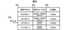
画像蓄積装置一覧を図8に示す。当該一覧は、画像蓄積装置のアドレスと性能等情報をまとめたテーブルであり、画像蓄積装置と通信するための宛先アドレス(801)、対応フォーマット(802)、及び、I/O性能(803)を各行に持つテーブルとして定義される。ポインタ(804)は、このテーブルの何れかの行を参照している。宛先アドレス801は具体的にはIPアドレスなどが該当する。また、対応フォーマット802にはmpeg2、mpeg4などの動画フォーマットの他、HTTP、RTPなど動画転送プロトコルの種類などの情報が含まれる。I/O性能803は当該動画蓄積装置に同時に書き込み可能な総ビットレートをあらわす。画像蓄積装置一覧中の対応フォーマット802及び、I/O性能803の情報は、後述の蓄積先割り当て情報テーブルの情報と合わせて用いることで、蓄積要求が受理されるか否かを予測するために、蓄積要求を送出する前に用いる。これにより処理の高速化を行うことができる。その詳細については後述する。 A list of image storage devices is shown in FIG. This list is a table that summarizes information such as the address and performance of the image storage device, and shows the destination address (801), the corresponding format (802), and the I / O performance (803) for communicating with the image storage device. Defined as a table with each row. The pointer (804) refers to any row of this table. Specifically, the
障害が発生すると(ステップ403)、ポインタが他の画像蓄積装置を指しているかチェックし(ステップ404)、自分自身を指しているならポインタを次の行へずらす(ステップ408)。次に、ポインタの指す画像蓄積装置に対して、現在実行中の画像蓄積に関する画像蓄積要求を送出する(ステップ405)。画像蓄積要求に対して、要求を送出した先の画像蓄積装置から、受理または非受理の応答が返される。要求が受理されるまでポインタをずらし、順次異なる画像蓄積装置に対して画像蓄積要求を送出する(ステップ406、408)。受理されたなら画像蓄積装置一覧を更新して処理を終了する(ステップ407)。 When a failure occurs (step 403), it is checked whether the pointer points to another image storage device (step 404), and if it points to itself, the pointer is shifted to the next line (step 408). Next, an image storage request relating to the image storage currently being executed is sent to the image storage device pointed to by the pointer (step 405). In response to the image storage request, a response of acceptance or non-acceptance is returned from the image storage device to which the request has been sent. The pointer is shifted until the request is accepted, and image storage requests are sequentially sent to different image storage devices (
次に、先に述べた画像蓄積要求の内容について、図9を用いて説明する。画像蓄積要求901は、画像入力装置の宛先アドレス(902)や、画像入力装置名やパスワードを含む認証用情報903や、蓄積する画像・音声のビットレートやコーデック(904〜907)といった情報からなる。画像蓄積装置は、画像入力装置の宛先アドレス902を用いて、画像を画像入力装置よりPULLすることもできる。画像入力装置が複数のコーデックやビットレートに対応している場合もあるため、コーデックやビットレート情報はリスト形式で記述される。 Next, the contents of the above-described image accumulation request will be described with reference to FIG. The
画像蓄積要求に対する応答内容を図10に示す。画像蓄積要求応答1001は、要求の受理または非受理を示す判定結果1002、受理の場合生成されたファイル名1003、画像ビットレート1004、画像コーデック1005、音声ビットレート1006、及び、音声コーデック1007からなる。画像蓄積要求901の、認証用情報903中の画像入力装置名は装置毎にユニークな名称とすることで、画像を記録するのに必要なファイル名の一部に利用することができる。例えば、ファイル名1003は画像入力装置毎にユニークな文字列+時刻から生成することができる。蓄積先選択装置102にて上記のようにファイル名を生成し、認証用情報の一部として上記ファイル名を画像蓄積要求中に書き込み画像蓄積装置103へ送出することで、システム全体でユニークなファイル名を生成することができる。 FIG. 10 shows the contents of the response to the image storage request. The image
次に、蓄積要求判定手順110の動作アルゴリズムについて、図5を用いて説明する。画像蓄積装置103の制御装置114は、蓄積要求を受信すると(ステップ501)、要求されたフォーマットに対応する画像書き込み手順プログラム111があるかチェックする。無ければ要求を拒否する(ステップ506)。次に、記憶装置112の空き容量をチェックする(ステップ502)。余裕が無ければ要求を拒否する(ステップ5
06)。そして、現在蓄積中の画像のビットレート及び読み出し中の画像のビットレートを計算しI/O性能に比して余裕があるかチェックする。余裕があれば要求を受理(ステップ505)。余裕が無ければ拒否(ステップ506)する。Next, the operation algorithm of the accumulation request determination procedure 110 will be described with reference to FIG. When receiving the storage request (step 501), the
06). Then, the bit rate of the image currently being stored and the bit rate of the image being read are calculated, and it is checked whether there is a margin compared to the I / O performance. If there is room, the request is accepted (step 505). If there is no allowance, it is rejected (step 506).
次に、上述の蓄積先割り当て状況テーブルについて、図11を用いて説明する。当該テーブルは、画像蓄積装置103のメモリ113に格納されており、画像入力装置毎にユニークとなる画像入力装置名(1101)、割り当てた蓄積先のアドレス(1102)、トータルのビットレート(1103)、フォーマット(1104)、記録時刻(1105)、ファイル名(1106)などの情報からなる。そして、当該テーブルは蓄積要求が画像蓄積装置103に受理される毎に追加される。例えば、ある蓄積先へ割り当てた総ビットレートを計算すれば、画像蓄積装置一覧中の画像蓄積装置I/O性能と比較することにより、要求が受理されるか否か実際に蓄積要求を送出することなく知る。I/O性能をビットレートの合計が上回れば要求は非受理、上回らなければ受理である。また、画像蓄積先が途中で変更した場合、元のファイルの記録時刻に記録終了時刻が書き込まれ、新たなファイルおよび蓄積先割り当て状況テーブルが生成される。 Next, the above-described storage destination allocation situation table will be described with reference to FIG. The table is stored in the memory 113 of the
図11の3行目〜4行目は画像蓄積先が変化した場合の例である。3行目がアドレス192.168.1.3を持つ元々の蓄積先に残された2001年10月1日1時3分から2002年11月1日10時1分までの動画データの存在を示し、4行目が2001年11月1日10時2分から現在も192.168.1.4のアドレスを持つ画像蓄積装置に画像蓄積中であることを示す。現在記録中でない上記3行目のようなエントリは画像視聴時にのみ用いられる。現在記録中のエントリは蓄積要求結果の予測にも用いられる。 The third to fourth lines in FIG. 11 are examples when the image storage destination is changed. The third line shows the existence of video data from 1: 3 on October 1, 2001 to 10:01 on November 1, 2002 that was left in the original storage destination with address 192.168.1.3. Indicates that images are being stored in the image storage device having the address of 192.168.1.4 from 10:02 on November 1, 2001. The entry on the third line that is not currently recorded is used only when viewing an image. The entry currently being recorded is also used for predicting the accumulation request result.
画像視聴時には先に述べたように画像視聴装置106より画像要求が送出される。蓄積先選択装置102上の蓄積先割り当て状況テーブルのうち、画像要求の内容に合致するものを選択しリストにしたものが、画像要求応答として画像視聴装置106へ応答される。 When viewing an image, an image request is sent from the image viewing device 106 as described above. Of the storage destination allocation status tables on the storage
蓄積先選択装置102にて、上述の画像蓄積装置一覧とこのテーブルを保持することにより、図4記載のアルゴリズムにて画像蓄積要求(405)の結果を予測することができる。これにより、無駄な画像蓄積要求の送出を削減しシステムの性能を向上することができる。 By storing the above-described image storage device list and this table in the storage
ここでは、これまでの説明で前提としてきた方式とは異なる方式にも、本発明を適用可能であることを示す。実施例1では、画像データの送受方法としてPULL方式を用いている。また、画像入力装置からの蓄積要求は蓄積先選択装置へPUSHする方式を用いている。しかし、画像データの送受方法にはPULL方式だけでなくPUSH方式を用いることもできる。更に、上記画像データの送受方法とは独立に、画像入力装置からの蓄積要求としてPUSH方式、PULL方式を選択できるので組み合わせると4つの実施例が考えられる。ここでは、実施例1とは逆に画像データ送受にPUSH方式、蓄積要求にPULL方式を用いた場合を例として、4つの実施例が可能であることを示す。 Here, it is shown that the present invention can be applied to a scheme different from the scheme assumed in the above description. In the first embodiment, the PULL method is used as the image data transmission / reception method. In addition, the storage request from the image input device uses a method of pushing to the storage destination selection device. However, not only the PULL method but also the PUSH method can be used for transmitting and receiving image data. Furthermore, since the PUSH method and the PULL method can be selected as a storage request from the image input device independently of the image data transmission / reception method, four embodiments can be considered when combined. Here, in contrast to the first embodiment, the case where the PUSH method is used for image data transmission / reception and the PULL method is used for the storage request is shown as an example, and four embodiments are possible.
図12を用いて全体の動作手順について述べる。そして、画像データの送受方法としてPUSH方式を用いた点について述べ、次に蓄積先選択装置が画像入力装置から蓄積要求をPULLする点について述べる。図12は、画像入力装置101により生成される画像が画像蓄積装置103内の記録装置112に格納されるまでのプロセス(ステップ1201〜1204)において、画像入力装置101、蓄積先選択装置保護装置105、蓄積先選択装置102、画像蓄積装置保護装置104、画像蓄積装置103、間の通信の流れを示しており、縦軸は上から下へ各装置の時間の流れを示す。横軸は装置間で矢印の示す方向へデータが送出されたことを示す。 The overall operation procedure will be described with reference to FIG. Then, the point that the PUSH method is used as the image data transmission / reception method will be described, and then the point that the storage destination selection device will pull the storage request from the image input device will be described. FIG. 12 shows the
まず、ステップ1201では蓄積先選択装置保護装置105を介して蓄積先選択装置102が画像入力装置101へ蓄積すべき画像があるか問い合わせる。この応答として蓄積要求が蓄積先選択装置へ送られる(PULL)。蓄積先選択装置102は複数の画像蓄積装置103から1台を選択し、蓄積要求を転送する。 First, in
画像蓄積装置103は上記要求に対して、応答を返す(ステップ1202)。また、要求を受理した場合には、画像蓄積装置保護装置104に対して画像データの通過を許可するよう要求を送出する(ステップ1203)。画像入力装置101は、蓄積要求が受理されたことをステップ1202の応答にて確認すると、画像データを画像蓄積装置へ送出する(ステップ1204)。この画像データは、ステップ1203の手順により保護装置を通過することが許可されているので、画像蓄積装置103に蓄積される。以上が、全体の動作手順である。 The
次に、PUSH方式を用いた画像データの送受について詳細を述べる。画像入力装置から画像蓄積装置に向けて画像を送出するPUSH方式では、ファイアウォールを通過することができない。そこで、2つの機能を追加している。まず、画像蓄積装置の書き込み手順に新たな手順を追加する。この新たな手順では、蓄積要求を受信するとともに画像蓄積装置を画像受信待機状態にする。次に、蓄積要求を画像蓄積装置に送出するのと同じタイミングで蓄積先選択装置102から画像蓄積装置保護装置104に、当該画像データが通過できる穴を開けるように指示する。これにより、PUSH方式、PULL方式の画像入力装置を混在させることもできる。従って、例えばすでにPUSH方式の画像入力装置が設置済みの監視システムを段階的に本発明方式に移行するといったことも可能である。画像蓄積装置からの指示で保護装置に穴をあけることにより、保護装置の穴を必要最小限に留めることができるが、外部ネットワークからのアクセスを全て遮断することができるPULL方式に比べてセキュリティ面で不利な構成となる。 Next, details of image data transmission / reception using the PUSH method will be described. In the PUSH system in which an image is transmitted from the image input device to the image storage device, it cannot pass through the firewall. Therefore, two functions are added. First, a new procedure is added to the writing procedure of the image storage device. In this new procedure, the storage request is received and the image storage apparatus is set in an image reception standby state. Next, the storage
最後に、PULL方式を用いた蓄積要求の送受について詳細を述べる。蓄積先選択装置が画像入力装置より蓄積要求をPULLする方式では、新たに蓄積先選択装置に予め全ての画像入力装置のアドレスを登録するための手順が必要になる。更に、画像入力装置はシステムを構成する装置のうちもっとも台数の多い装置と考えられるため、故障等障害の発生確率も高く、機器の一時撤去に伴うアドレス更新など管理コストを増大させる恐れもある。逆に、メリットとしては、監視対象エリアにある画像入力装置ネットワークからの蓄積先選択装置に対するアクセスを全て遮断できるため、セキュリティ面で有利なシステムを構築することができる。 Finally, the details of sending and receiving storage requests using the PULL method will be described. In the method in which the storage destination selection device pulls the storage request from the image input device, a procedure for newly registering the addresses of all the image input devices in the storage destination selection device is required. Furthermore, since the image input device is considered to be the device with the largest number among the devices constituting the system, the probability of occurrence of a failure such as a failure is high, and there is a risk of increasing the management cost such as updating the address when the device is temporarily removed. On the other hand, as an advantage, since it is possible to block all accesses to the storage destination selection device from the image input device network in the monitoring target area, it is possible to construct a system advantageous in terms of security.
上述の実施例では、蓄積先選択装置保護装置、及び、画像蓄積装置保護装置を、それぞれ独立した装置として記載したが、これら保護装置は当該機能を、それぞれ蓄積先選択装置および画像蓄積装置に内蔵して実施することもできる。 In the above-described embodiment, the storage destination selection device protection device and the image storage device protection device are described as independent devices, but these protection devices have the functions incorporated in the storage destination selection device and the image storage device, respectively. It can also be implemented.
上述の実施例では、蓄積先選択装置、及び、画像蓄積装置を、それぞれ独立した装置として記載したが、当該機能を同一の装置上で実施することもできる。具体的には1台の装置に複数のディスク・ボリュームが接続されている場合である。ディスク・ボリューム及び当該ディスク・ボリュームにデータを書き込むプログラムは上述の画像蓄積装置に相当し、複数のディスク・ボリュームから書き込み先ボリュームを選択するプログラムが蓄積先選択装置に相当する。このとき、ディスク・ボリュームを選択するプログラムからディスク・ボリュームに書き込みを行うプログラムに対して制御データを渡すことは、上述の実施例で述べた蓄積先選択装置から画像蓄積装置への制御データの送信に相当する。 In the above-described embodiments, the storage destination selection device and the image storage device are described as independent devices, but the function can be performed on the same device. Specifically, this is a case where a plurality of disk volumes are connected to one device. A disk volume and a program for writing data to the disk volume correspond to the above-described image storage device, and a program for selecting a write destination volume from a plurality of disk volumes corresponds to the storage destination selection device. At this time, passing the control data from the program for selecting the disk volume to the program for writing to the disk volume means that the control data is transmitted from the storage destination selecting apparatus described in the above embodiment to the image storage apparatus. It corresponds to.
上述の実施例では、制御データと画像データを分離して、蓄積先選択装置を経由して制御データを画像蓄積装置に送出した。しかし、制御データが経由する装置は、蓄積先選択機能をもつ装置に限らない。例えば、画像蓄積装置が1台の場合には、蓄積先選択装置のかわりに単なる中継装置を用いることができる。制御データを送受する経路上の中継装置から画像蓄積装置へ制御データを送出することは、上述の実施例で述べた蓄積先選択装置から画像蓄積装置への制御データの送信に相当する。このような実施においても、制御データはレイテンシのできるだけ小さい経路で送受して、画像データはできるだけスループットの大きい経路で送受することができるなど、制御データと画像データを分離することによるメリットがある。 In the above-described embodiment, the control data and the image data are separated, and the control data is sent to the image storage device via the storage destination selection device. However, the device through which the control data passes is not limited to a device having a storage destination selection function. For example, when there is one image storage device, a simple relay device can be used instead of the storage destination selection device. Sending control data from the relay device on the path for transmitting and receiving control data to the image storage device corresponds to transmission of control data from the storage destination selection device to the image storage device described in the above-described embodiment. Even in such an implementation, there is a merit by separating the control data and the image data, such that the control data can be transmitted and received through a path with as low latency as possible, and the image data can be transmitted and received through a path with as high a throughput as possible.
101 画像入力装置、102 蓄積先選択装置、103 画像蓄積装置、104 画像蓄積装置保護装置、105 蓄積先選択装置保護装置、106 画像視聴装置、112 記憶装置、113 メモリ、114 制御装置、115 インターフェース
DESCRIPTION OF
Claims (10)
Translated fromJapanese前記第一の装置は、第一の制御装置と、第一のメモリを有し、
前記第一のメモリは、制御データを前記第二の装置に送出し、実データを前記第三の装置に送出するための第一のプログラムを格納し、
前記第二の装置は、第二の制御装置と、第二のメモリを有し、
前記第二のメモリは、前記第一の装置から受信した前記制御データに応じて前記第三の装置に前記制御データを送出するための第二のプログラムを格納し、
前記第三の装置は、第三の制御装置と、第三のメモリと、記憶装置を有し、
前記第三のメモリは、前記第二の装置から受信した前記制御データに応じて、前記第一の装置から受信した前記実データを前記記憶装置に格納するための第三のプログラムを格納し、
前記第一の制御装置は、前記第一のプログラムを、前記第二の制御装置は、前記第二のプログラムを、前記第三の制御装置は、前記第三のプログラムをそれぞれ実行する、システム。In a system in which a first device to which data is input, a second device that selects a data storage destination, and a third device that stores data are interconnected,
The first device has a first control device and a first memory,
The first memory stores a first program for sending control data to the second device and sending actual data to the third device;
The second device has a second control device and a second memory,
The second memory stores a second program for sending the control data to the third device according to the control data received from the first device,
The third device includes a third control device, a third memory, and a storage device,
The third memory stores a third program for storing the actual data received from the first device in the storage device according to the control data received from the second device,
The first control device executes the first program, the second control device executes the second program, and the third control device executes the third program.
前記第六の装置は、第六の制御装置と、第六のメモリを有し、
前記第六のメモリは、前記第二の装置に蓄積先を問い合わせ、当該問い合わせの返答に応じて、前記第三の装置から実データを取得するための第六のプログラムを格納し、
前記第六の制御装置は、前記第六のプログラムを実行する、請求項1記載のシステム。A sixth device for viewing the actual data is connected to the second device;
The sixth device has a sixth control device and a sixth memory,
The sixth memory stores a sixth program for inquiring about the storage destination of the second device, and for acquiring actual data from the third device in response to a response to the inquiry,
The system according to claim 1, wherein the sixth control device executes the sixth program.
前記第三の制御装置は、前記テーブルに応じて、前記第二の装置から受信した制御データに関する実データを受理するか否かを決定する、請求項1記載のシステム。The third memory stores a table indicating a storage destination situation,
The system according to claim 1, wherein the third control device determines whether to accept actual data related to control data received from the second device, according to the table.
第三の装置に障害が発生した場合、当該第三の装置内の第三の制御装置は、他の第三の装置に対して、制御データを送出し、当該制御データに対する返答に応じて、前記他の第三の装置に実データを送出する、請求項1記載のシステム。Multiple third devices are connected,
When a failure occurs in the third device, the third control device in the third device sends control data to the other third device, and in response to a response to the control data, The system according to claim 1, wherein actual data is sent to the other third device.
前記第一の装置は、第一の制御装置と、第一のメモリを有し、
前記第一のメモリは、制御データを前記第二の装置に送出し、実データを前記第三の装置に送出するための第一のプログラムを格納し、
前記第二の装置は、第二の制御装置と、第二のメモリを有し、
前記第二のメモリは、前記第一の装置から受信した前記制御データを中継して前記第三の装置に前記制御データを送出するための第二のプログラムを格納し、
前記第三の装置は、第三の制御装置と、第三のメモリと、記憶装置を有し、
前記第三のメモリは、前記第二の装置から受信した前記制御データに応じて、前記第一の装置から受信した前記実データを前記記憶装置に格納するための第三のプログラムを格納し、
前記第一の制御装置は、前記第一のプログラムを、前記第二の制御装置は、前記第二のプログラムを、前記第三の制御装置は、前記第三のプログラムをそれぞれ実行する、システム。In a system in which a first device to which data is input, a second device that relays data, and a third device that stores data are interconnected,
The first device has a first control device and a first memory,
The first memory stores a first program for sending control data to the second device and sending actual data to the third device;
The second device has a second control device and a second memory,
The second memory stores a second program for relaying the control data received from the first device and sending the control data to the third device;
The third device includes a third control device, a third memory, and a storage device,
The third memory stores a third program for storing the actual data received from the first device in the storage device according to the control data received from the second device,
The first control device executes the first program, the second control device executes the second program, and the third control device executes the third program.
前記第六の装置は、第六の制御装置と、第六のメモリを有し、
前記第六のメモリは、前記第二の装置に蓄積先を問い合わせ、当該問い合わせの返答に応じて、前記第三の装置から実データを取得するための第六のプログラムを格納し、
前記第六の制御装置は、前記第六のプログラムを実行する、請求項6記載のシステム。A sixth device for viewing the actual data is connected to the second device;
The sixth device has a sixth control device and a sixth memory,
The sixth memory stores a sixth program for inquiring about the storage destination of the second device, and for acquiring actual data from the third device in response to a response to the inquiry,
The system according to claim 6, wherein the sixth control device executes the sixth program.
前記第三の制御装置は、前記テーブルに応じて、前記第二の装置から受信した制御データに関する実データを受理するか否かを決定する、請求項6記載のシステム。The third memory stores a table indicating a storage destination situation,
The system according to claim 6, wherein the third control device determines whether to accept actual data related to control data received from the second device, according to the table.
第三の装置に障害が発生した場合、当該第三の装置内の第三の制御装置は、他の第三の装置に対して、制御データを送出し、当該制御データに対する返答に応じて、前記他の第三の装置に実データを送出する、請求項6記載のシステム。
Multiple third devices are connected,
When a failure occurs in the third device, the third control device in the third device sends control data to the other third device, and in response to a response to the control data, The system according to claim 6, wherein actual data is sent to the other third device.
Priority Applications (2)
| Application Number | Priority Date | Filing Date | Title |
|---|---|---|---|
| JP2004307584AJP2006119941A (en) | 2004-10-22 | 2004-10-22 | Moving image storage method |
| US11/002,697US7643722B2 (en) | 2004-10-22 | 2004-12-01 | Video storage system |
Applications Claiming Priority (1)
| Application Number | Priority Date | Filing Date | Title |
|---|---|---|---|
| JP2004307584AJP2006119941A (en) | 2004-10-22 | 2004-10-22 | Moving image storage method |
Publications (1)
| Publication Number | Publication Date |
|---|---|
| JP2006119941Atrue JP2006119941A (en) | 2006-05-11 |
Family
ID=36207302
Family Applications (1)
| Application Number | Title | Priority Date | Filing Date |
|---|---|---|---|
| JP2004307584APendingJP2006119941A (en) | 2004-10-22 | 2004-10-22 | Moving image storage method |
Country Status (2)
| Country | Link |
|---|---|
| US (1) | US7643722B2 (en) |
| JP (1) | JP2006119941A (en) |
Cited By (5)
| Publication number | Priority date | Publication date | Assignee | Title |
|---|---|---|---|---|
| JP2009157846A (en)* | 2007-12-27 | 2009-07-16 | Toshiba Tec Corp | Flow line data editing apparatus and flow line data editing program |
| JP2009260838A (en)* | 2008-04-18 | 2009-11-05 | Canon Inc | Monitoring device and control method thereof, and program |
| US8312211B2 (en) | 2008-05-23 | 2012-11-13 | Fujitsu Limited | Disk array apparatus, method for application of control firmware, and controlling unit for controlling application of control firmware |
| JP2013088998A (en)* | 2011-10-18 | 2013-05-13 | Buffalo Inc | Network storage system, data operation method in network storage system, storage device, and computer program for controlling client device |
| JP6042013B1 (en)* | 2016-05-16 | 2016-12-14 | 一般財団法人首都高速道路技術センター | Inspection information management system and inspection information management method |
Families Citing this family (12)
| Publication number | Priority date | Publication date | Assignee | Title |
|---|---|---|---|---|
| US20070208619A1 (en)* | 2005-09-30 | 2007-09-06 | Bellsouth Intellectual Property Corporation | Methods, systems, and computer program products for providing targeted advertising to communications devices |
| US8223938B2 (en) | 2005-09-30 | 2012-07-17 | At&T Intellectual Property I, L.P. | Methods, systems, and computer program products for providing caller identification services |
| US7890552B2 (en)* | 2005-09-30 | 2011-02-15 | At&T Intellectual Property I, L.P. | Methods, systems, and computer program products for implementing media content analysis, distribution, and re-allocation services |
| US20070209054A1 (en)* | 2005-09-30 | 2007-09-06 | Bellsouth Intellectual Property Corporation | Methods, systems, and computer program products for providing communications services |
| US8804695B2 (en)* | 2005-09-30 | 2014-08-12 | At&T Intellectual Property I, L.P. | Methods, systems, and computer program products for providing alerts and notifications |
| JP4696089B2 (en)* | 2007-03-30 | 2011-06-08 | 三菱電機インフォメーションシステムズ株式会社 | Distributed storage system |
| JP2012023685A (en)* | 2010-07-16 | 2012-02-02 | Toshiba Corp | Recording control device and recording control method |
| TWI496458B (en)* | 2011-12-30 | 2015-08-11 | Amtran Technology Co Ltd | Television receiving device providing a real time live video data stream file and method thereof |
| CN105812902B (en)* | 2016-03-17 | 2018-09-04 | 联发科技(新加坡)私人有限公司 | Method, equipment and the system of data playback |
| US11475112B1 (en) | 2016-09-12 | 2022-10-18 | Verint Americas Inc. | Virtual communications identification system with integral archiving protocol |
| CN110874185B (en)* | 2018-09-04 | 2021-12-17 | 杭州海康威视系统技术有限公司 | Data storage method and storage device |
| US11863815B2 (en) | 2019-09-17 | 2024-01-02 | Lightmetrics Technologies Pvt. Ltd. | Methods and systems for managing storage of videos in a storage device |
Citations (9)
| Publication number | Priority date | Publication date | Assignee | Title |
|---|---|---|---|---|
| JPH03219360A (en)* | 1990-01-24 | 1991-09-26 | Nec Corp | Multiprocessor control system |
| JPH05210612A (en)* | 1992-01-30 | 1993-08-20 | Nec Corp | Remote procedure calling system |
| JPH1185694A (en)* | 1997-09-11 | 1999-03-30 | Fujitsu Ltd | Server operation system |
| JP2000125062A (en)* | 1998-10-15 | 2000-04-28 | Canon Inc | Data communication system, data communication device, control method therefor, and storage medium |
| JP2000207374A (en)* | 1999-01-11 | 2000-07-28 | Toshiba Corp | Distributed processing computer system |
| JP2000268012A (en)* | 1999-03-12 | 2000-09-29 | Nec Corp | Method and device for distributing load in client server system |
| JP2003046552A (en)* | 2001-07-30 | 2003-02-14 | Fujitsu Ltd | Data processing program and data processing apparatus |
| JP2003224840A (en)* | 2002-01-31 | 2003-08-08 | Toshiba Corp | Image selection distribution system and image selection distribution method |
| JP2004272339A (en)* | 2003-03-05 | 2004-09-30 | Tokyo Inst Of Technol | Storage control device, storage control program, and storage control method |
Family Cites Families (15)
| Publication number | Priority date | Publication date | Assignee | Title |
|---|---|---|---|---|
| JP3635712B2 (en)* | 1995-04-08 | 2005-04-06 | ソニー株式会社 | Image information decoding apparatus and image information reproducing apparatus |
| JPH099195A (en)* | 1995-06-19 | 1997-01-10 | Matsushita Electric Ind Co Ltd | Moving picture storage device and moving picture storage method |
| US5826014A (en)* | 1996-02-06 | 1998-10-20 | Network Engineering Software | Firewall system for protecting network elements connected to a public network |
| JP3217002B2 (en)* | 1996-11-19 | 2001-10-09 | 株式会社日立製作所 | Digital studio apparatus and control method thereof |
| JP3369445B2 (en)* | 1997-09-22 | 2003-01-20 | 富士通株式会社 | Network service server load adjusting device, method and recording medium |
| US7055173B1 (en)* | 1997-12-19 | 2006-05-30 | Avaya Technology Corp. | Firewall pooling in a network flowswitch |
| US6941374B1 (en)* | 1999-08-05 | 2005-09-06 | Amazon.Com, Inc. | Hidden agent transfer protocol |
| US6880089B1 (en)* | 2000-03-31 | 2005-04-12 | Avaya Technology Corp. | Firewall clustering for multiple network servers |
| WO2002001439A2 (en)* | 2000-06-29 | 2002-01-03 | Musicgenome.Com Inc. | Using a system for prediction of musical preferences for the distribution of musical content over cellular networks |
| AU2001288463A1 (en)* | 2000-08-30 | 2002-03-13 | Citibank, N.A. | Method and system for internet hosting and security |
| US7093288B1 (en)* | 2000-10-24 | 2006-08-15 | Microsoft Corporation | Using packet filters and network virtualization to restrict network communications |
| WO2002101516A2 (en)* | 2001-06-13 | 2002-12-19 | Intruvert Networks, Inc. | Method and apparatus for distributed network security |
| US7676562B2 (en)* | 2004-01-20 | 2010-03-09 | Microsoft Corporation | Computer system for accessing instrumentation information |
| US7401355B2 (en)* | 2004-04-30 | 2008-07-15 | Sun Microsystems | Firewall load balancing using a single physical device |
| US8028334B2 (en)* | 2004-12-14 | 2011-09-27 | International Business Machines Corporation | Automated generation of configuration elements of an information technology system |
- 2004
- 2004-10-22JPJP2004307584Apatent/JP2006119941A/enactivePending
- 2004-12-01USUS11/002,697patent/US7643722B2/enactiveActive
Patent Citations (9)
| Publication number | Priority date | Publication date | Assignee | Title |
|---|---|---|---|---|
| JPH03219360A (en)* | 1990-01-24 | 1991-09-26 | Nec Corp | Multiprocessor control system |
| JPH05210612A (en)* | 1992-01-30 | 1993-08-20 | Nec Corp | Remote procedure calling system |
| JPH1185694A (en)* | 1997-09-11 | 1999-03-30 | Fujitsu Ltd | Server operation system |
| JP2000125062A (en)* | 1998-10-15 | 2000-04-28 | Canon Inc | Data communication system, data communication device, control method therefor, and storage medium |
| JP2000207374A (en)* | 1999-01-11 | 2000-07-28 | Toshiba Corp | Distributed processing computer system |
| JP2000268012A (en)* | 1999-03-12 | 2000-09-29 | Nec Corp | Method and device for distributing load in client server system |
| JP2003046552A (en)* | 2001-07-30 | 2003-02-14 | Fujitsu Ltd | Data processing program and data processing apparatus |
| JP2003224840A (en)* | 2002-01-31 | 2003-08-08 | Toshiba Corp | Image selection distribution system and image selection distribution method |
| JP2004272339A (en)* | 2003-03-05 | 2004-09-30 | Tokyo Inst Of Technol | Storage control device, storage control program, and storage control method |
Cited By (5)
| Publication number | Priority date | Publication date | Assignee | Title |
|---|---|---|---|---|
| JP2009157846A (en)* | 2007-12-27 | 2009-07-16 | Toshiba Tec Corp | Flow line data editing apparatus and flow line data editing program |
| JP2009260838A (en)* | 2008-04-18 | 2009-11-05 | Canon Inc | Monitoring device and control method thereof, and program |
| US8312211B2 (en) | 2008-05-23 | 2012-11-13 | Fujitsu Limited | Disk array apparatus, method for application of control firmware, and controlling unit for controlling application of control firmware |
| JP2013088998A (en)* | 2011-10-18 | 2013-05-13 | Buffalo Inc | Network storage system, data operation method in network storage system, storage device, and computer program for controlling client device |
| JP6042013B1 (en)* | 2016-05-16 | 2016-12-14 | 一般財団法人首都高速道路技術センター | Inspection information management system and inspection information management method |
Also Published As
| Publication number | Publication date |
|---|---|
| US20060089980A1 (en) | 2006-04-27 |
| US7643722B2 (en) | 2010-01-05 |
Similar Documents
| Publication | Publication Date | Title |
|---|---|---|
| JP2006119941A (en) | Moving image storage method | |
| JP5368860B2 (en) | Information collection system | |
| CA2390621C (en) | Internet video surveillance camera system and method | |
| EP1411678B1 (en) | Method and system for content-oriented routing of packets in a storage-embedded network | |
| US20190132282A1 (en) | Ndn and ip fusion network content control method and apparatus, and storage medium | |
| JP7097427B2 (en) | Data processing system and data processing method | |
| JP2013258700A (en) | System for dynamic stream management in audio video bridged networks | |
| US9537930B2 (en) | Information system, file server, and file server control method | |
| JP5255035B2 (en) | Failover system, storage processing apparatus, and failover control method | |
| JP2019009610A (en) | Edge device, data processing system, data transmission method, and program | |
| JP4949448B2 (en) | Network connector device | |
| US20090073973A1 (en) | Router having black box function and network system including the same | |
| US10146953B1 (en) | System and method for physical data packets isolation for different tenants in a multi-tenant protection storage environment | |
| US12438848B2 (en) | Discovery and assignment of privacy-protecting relays in a network | |
| KR20160026573A (en) | Surveillance system | |
| JP4397894B2 (en) | Video distribution apparatus and video distribution program | |
| JP6875474B2 (en) | Communication system and communication method | |
| US8903970B2 (en) | Explicit logging of network user node/target node coupling | |
| KR200422878Y1 (en) | Multi-hop based DWR multi access device | |
| KR101093808B1 (en) | Network system sharing data storage device and its operation method | |
| JP4597882B2 (en) | Packet search management apparatus and packet search management method | |
| KR101401013B1 (en) | METHOD AND METHOD FOR PROCESSING PACKET | |
| JP2009224895A (en) | Video image distributing system | |
| JP2008148347A (en) | Image storage and delivery system | |
| JP2006157293A (en) | Server, communication terminal and communication system |
Legal Events
| Date | Code | Title | Description |
|---|---|---|---|
| RD04 | Notification of resignation of power of attorney | Free format text:JAPANESE INTERMEDIATE CODE: A7424 Effective date:20060523 | |
| A621 | Written request for application examination | Free format text:JAPANESE INTERMEDIATE CODE: A621 Effective date:20070115 | |
| RD04 | Notification of resignation of power of attorney | Free format text:JAPANESE INTERMEDIATE CODE: A7424 Effective date:20071012 | |
| RD04 | Notification of resignation of power of attorney | Free format text:JAPANESE INTERMEDIATE CODE: A7424 Effective date:20090217 | |
| A977 | Report on retrieval | Free format text:JAPANESE INTERMEDIATE CODE: A971007 Effective date:20091120 | |
| A131 | Notification of reasons for refusal | Free format text:JAPANESE INTERMEDIATE CODE: A131 Effective date:20091224 | |
| A521 | Request for written amendment filed | Free format text:JAPANESE INTERMEDIATE CODE: A523 Effective date:20100216 | |
| A02 | Decision of refusal | Free format text:JAPANESE INTERMEDIATE CODE: A02 Effective date:20100616 |