JP2006119893A - Input device - Google Patents
Input deviceDownload PDFInfo
- Publication number
- JP2006119893A JP2006119893AJP2004306917AJP2004306917AJP2006119893AJP 2006119893 AJP2006119893 AJP 2006119893AJP 2004306917 AJP2004306917 AJP 2004306917AJP 2004306917 AJP2004306917 AJP 2004306917AJP 2006119893 AJP2006119893 AJP 2006119893A
- Authority
- JP
- Japan
- Prior art keywords
- power
- speed
- input device
- power generation
- input
- Prior art date
- Legal status (The legal status is an assumption and is not a legal conclusion. Google has not performed a legal analysis and makes no representation as to the accuracy of the status listed.)
- Pending
Links
Images


Classifications
- G—PHYSICS
- G06—COMPUTING OR CALCULATING; COUNTING
- G06F—ELECTRIC DIGITAL DATA PROCESSING
- G06F3/00—Input arrangements for transferring data to be processed into a form capable of being handled by the computer; Output arrangements for transferring data from processing unit to output unit, e.g. interface arrangements
- G06F3/01—Input arrangements or combined input and output arrangements for interaction between user and computer
- G06F3/03—Arrangements for converting the position or the displacement of a member into a coded form
- G06F3/033—Pointing devices displaced or positioned by the user, e.g. mice, trackballs, pens or joysticks; Accessories therefor
- G06F3/0346—Pointing devices displaced or positioned by the user, e.g. mice, trackballs, pens or joysticks; Accessories therefor with detection of the device orientation or free movement in a 3D space, e.g. 3D mice, 6-DOF [six degrees of freedom] pointers using gyroscopes, accelerometers or tilt-sensors
- G—PHYSICS
- G06—COMPUTING OR CALCULATING; COUNTING
- G06F—ELECTRIC DIGITAL DATA PROCESSING
- G06F1/00—Details not covered by groups G06F3/00 - G06F13/00 and G06F21/00
- G06F1/26—Power supply means, e.g. regulation thereof
Landscapes
- Engineering & Computer Science (AREA)
- Theoretical Computer Science (AREA)
- General Engineering & Computer Science (AREA)
- Physics & Mathematics (AREA)
- General Physics & Mathematics (AREA)
- Human Computer Interaction (AREA)
- Connection Of Motors, Electrical Generators, Mechanical Devices, And The Like (AREA)
- Power Sources (AREA)
- Position Input By Displaying (AREA)
- Permanent Magnet Type Synchronous Machine (AREA)
Abstract
Description
Translated fromJapanese本発明は入力装置に係り、特に、操作時に発生する加速度に応じて入力信号を生成、送出する入力装置に関する。 The present invention relates to an input device, and more particularly to an input device that generates and sends an input signal in accordance with acceleration generated during operation.
コンピュータは、各種入力デバイスにより入力、あるいは、操作を行なっている。入力デバイスとしては、キーボードやマウスが一般的である。このうちマウスは、本体を机上で移動させることにより、ディスプレイ装置に表示されたポインタを移動させる。 The computer performs input or operation with various input devices. As an input device, a keyboard and a mouse are generally used. Among these, the mouse moves the pointer displayed on the display device by moving the main body on the desk.
近年、大型のディスプレイ装置が普及するにつれて、コンピュータを離れた位置から操作したいという要求がある。また、この場合、入力を中空で行ないたいという要求がある。このため、3次元入力が可能な入力装置が提案されている。 In recent years, as large-sized display devices become widespread, there is a demand for operating a computer from a remote location. Further, in this case, there is a demand for input to be hollow. For this reason, input devices capable of three-dimensional input have been proposed.
3次元入力が可能な入力装置は、ジャイロ及び加速度センサなどを内蔵しており、ジャイロにより装置本体の角速度を測定し、加速度センサにより装置本体の加速度を測定することにより、装置本体の中空での動きに応じた検出データを生成し、検出データを無線などによりコンピュータに送信することにより、入力を可能としている(特許文献1参照)。 An input device capable of three-dimensional input includes a gyro, an acceleration sensor, and the like, and measures the angular velocity of the device main body with the gyro and measures the acceleration of the device main body with the acceleration sensor. Input is possible by generating detection data corresponding to the movement and transmitting the detection data to a computer by wireless or the like (see Patent Document 1).
また、マウスなどの入力装置では、コンピュータを離れた位置から操作する場合、マウスとコンピュータとの間の配線が長くなり、操作性、取り回しなどが悪くなるので、無線でデータを送信する必要があった。このように無線でデータを送信する入力装置では、内部回路を駆動するために電源を内蔵する必要があった。従来、内蔵される電源は、電池などであった。 In addition, in an input device such as a mouse, when operating the computer from a remote position, the wiring between the mouse and the computer becomes long, and operability and handling are deteriorated. Therefore, it is necessary to transmit data wirelessly. It was. Thus, in an input device that transmits data wirelessly, it is necessary to incorporate a power source in order to drive the internal circuit. Conventionally, a built-in power source has been a battery or the like.
電池駆動の場合、電池が消耗したときには、交換が必要となる。使用頻度が多い、あるいは、使用時間が長い場合には、使用中に電池交換が必要となる場合もある。このため、装置のメンテナンスが煩雑になるなどの課題があった。 In the case of battery driving, when the battery is exhausted, replacement is necessary. When the frequency of use is high or the usage time is long, the battery may need to be replaced during use. For this reason, there existed problems, such as the maintenance of an apparatus becoming complicated.
電池交換を不要とするために、発電機及び二次電池を内蔵した無線マウス装置があった(特許文献2参照)。このような無線マウス装置では、位置を検出するためのボールの回転により発電機を駆動して二次電池に蓄電する構成とされていた。このため、それ程大きな電力を発生することができなかった。 In order to eliminate the need for battery replacement, there has been a wireless mouse device incorporating a generator and a secondary battery (see Patent Document 2). In such a wireless mouse device, the generator is driven by the rotation of a ball for detecting the position and the secondary battery is charged. For this reason, it was not possible to generate such a large amount of power.
また、リモコン装置などにでも電池交換を不要とするために、発電機を内蔵したリモコン装置が提案されている(特許文献3参照)。このリモコン装置は、ユーザがリングを回転する操作を行なうことにより、発電及び制御コマンドを送信する構成とされていた。 In order to eliminate the need for battery replacement even in a remote control device or the like, a remote control device incorporating a generator has been proposed (see Patent Document 3). This remote control device is configured to transmit power generation and control commands by the user performing an operation of rotating the ring.
しかるに、従来の無線式入力装置は、一般に電池により駆動されていたため、電池が消耗した場合には、電池交換が必要となる。使用頻度が多い、あるいは、使用時間が長い場合には、使用中に電池交換が必要となる場合もある。このため、装置のメンテナンスが煩雑になるなどの課題があった。 However, since the conventional wireless input device is generally driven by a battery, the battery needs to be replaced when the battery is exhausted. When the frequency of use is high or the usage time is long, the battery may need to be replaced during use. For this reason, there existed problems, such as the maintenance of an apparatus becoming complicated.
本発明は上記の点に鑑みてなされたもので、電池交換などのメンテナンスが不要な入力装置を提供することを目的とする。 The present invention has been made in view of the above points, and an object thereof is to provide an input device that does not require maintenance such as battery replacement.
本発明は、本体に働く加速度を検出し、検出した加速度に応じた検出信号を出力する入力手段を有する入力装置において、本体に働く加速度に応じて発電を行なう発電手段と、発電手段で発電された電力を蓄える蓄電手段と、発電手段で発電された電力又は蓄電手段に蓄えられた電力により入力手段を駆動する電源を生成する電源生成手段とを有することを特徴とする。 The present invention provides an input device having an input unit that detects acceleration acting on a main body and outputs a detection signal corresponding to the detected acceleration, and generates power by the power generation unit. Power storage means for storing the generated power, and power generation means for generating a power source for driving the input means by the power generated by the power generation means or the power stored in the power storage means.
本発明によれば、本体に働く加速度に応じて発電を行なう発電手段と、発電手段で発電された電力を蓄える蓄電手段と、発電手段で発電された電力又は蓄電手段に蓄えられた電力により入力手段を駆動する電源を生成する電源生成手段とを有することにより、装置本体に働く加速度に応じて電力が発生させ、蓄電することができるため、比較的多くの電力を得ることができ、電池交換なく、装置を駆動させることができ、また、操作動作に応じて電力が生成されるため、使用頻度、あるいは、長時間使用によらず、装置を駆動させることができ、したがって、メンテナンスが不要となるなどの特長を有する。 According to the present invention, the power generation means for generating power according to the acceleration acting on the main body, the power storage means for storing the power generated by the power generation means, the power generated by the power generation means or the power stored in the power storage means is input. By having power generation means for generating power to drive the means, power can be generated and stored according to the acceleration acting on the main body of the device, so that a relatively large amount of power can be obtained and battery replacement The device can be driven, and electric power is generated according to the operation, so that the device can be driven regardless of the frequency of use or long-term use, and therefore no maintenance is required. It has features such as
〔第1実施例〕
〔システム構成〕
図1は本発明の第1実施例のシステム構成図を示す。[First embodiment]
〔System configuration〕
FIG. 1 shows a system configuration diagram of a first embodiment of the present invention.
本実施例のシステム1は、入力装置10、通信ユニット20、接続ケーブル30、コンピュータ装置40、接続ケーブル50、ディスプレイ60から構成されている。 The
入力装置10は、装置本体を空間で3次元方向に動かすことにより、ディスプレイ60の表示面に表示されるポインタPの動きを制御する。例えば、入力装置10を矢印X1、Y1、Z1方向に動かすことにより、ディスプレイ60の画面上で、ポインタPをそれに対応する矢印x1、y1方向に移動させるための座標データを生成し、通信ユニット20に向けて無線送信する。また、スイッチ類の操作により操作情報である入力データを生成し、通信ユニット20に向けて無線送信する。 The
通信ユニット20は、無線LANユニット、ポイントツーポイント接続が可能な無線通信システムから構成されており、入力装置10から送出された座標データ及び入力データを受信する。通信ユニット20は、接続ケーブル30を介してコンピュータ装置40に接続されている。通信ユニット20とコンピュータ装置40とは、例えば、USBインタフェースにより接続されている。通信ユニット20は、受信した座標データ及び入力データを、接続ケーブル30を通してコンピュータ装置40に送信する。 The
コンピュータ装置40は、接続ケーブル50を介してディスプレイ60に接続されている。コンピュータ装置40は、通信ユニット20から供給される座標データに基づいてディスプレイ60に表示されるポインタPの位置を移動させる。また、コンピュータ装置40は、通信ユニット20から供給される入力データに基づいてアイコンを選択したり、プログラムを実行したりする。ディスプレイ60は、例えば、CRTやLCDなどから構成されており、コンピュータ装置40から供給される表示データに応じた画面を表示する。 The
〔入力装置10〕
次に入力装置10について説明を行なう。[Input device 10]
Next, the
図2は入力装置10の断面図、図3は入力装置10のブロック構成図を示す。 FIG. 2 is a cross-sectional view of the
本実施例の入力装置10は、座標検出手段111、入力手段112、処理手段113、通信手段114、電源生成手段115、蓄電手段116、発電手段117から構成され、ケース118、上カバー119、下カバー120により構成される収容部に収容される。 The
座標検出手段111は、ジャイロや加速度センサから構成されており、回路基板PC1上に搭載され、操作者の動きに応じた検出信号を出力する。例えば、ジャイロの場合には、装置本体の回転角度を検出し、検出した回転角度に応じた検出信号を出力する。また、加速度センサの場合には、装置本体に働く加速度を検出し、検出した加速度に応じた検出信号を出力する。 The coordinate detection means 111 is composed of a gyroscope and an acceleration sensor, is mounted on the circuit board PC1, and outputs a detection signal corresponding to the movement of the operator. For example, in the case of a gyro, the rotation angle of the apparatus main body is detected, and a detection signal corresponding to the detected rotation angle is output. In the case of an acceleration sensor, an acceleration acting on the apparatus main body is detected, and a detection signal corresponding to the detected acceleration is output.
入力手段112は、スイッチ、ポインティングデバイスなどから構成されており、回路基板PC2、PC3、PC4上に搭載されており、スイッチ操作に応じた入力信号を生成する。例えば、スイッチがオンのときには、ハイレベル、スイッチがオフのときには、ローレベルとなるような入力信号を出力する。 The
処理手段113は、回路基板PC4上に搭載されており、座標検出手段111から供給される検出信号から座標データを生成するとともに、入力手段112からの入力信号から入力データを生成する。処理手段113で生成された座標データ及び入力データは、通信手段114に供給される。 The
通信手段114は、回路基板PC2上に搭載されており、処理手段113から供給された座標データ及び入力データに基づいて搬送波を変調、増幅して、通信ユニット20に向けて無線送信する。 The
電源生成手段115は、例えば、スイッチングレギュレータ、シリーズレギュレータ、或いは、定電圧回路などの電源回路から構成されており、回路基板PC4上に搭載されており、蓄電手段116に蓄えられた電力から、座標検出手段111、入力手段112、処理手段113、通信手段114を駆動するための駆動電圧を生成する。 The power generation means 115 is composed of, for example, a power supply circuit such as a switching regulator, a series regulator, or a constant voltage circuit. The power generation means 115 is mounted on the circuit board PC4, and coordinates are calculated from the electric power stored in the power storage means 116. A drive voltage for driving the
蓄電手段116は、ケース118内に収納されており、電解コンデンサ、又は、電気二重層コンデンサ、又は、リチウムイオン電池などの二次電池から構成されており、発電手段115で発電された電力を蓄積するとともに、蓄積された電力を電源生成手段115に供給する。 The power storage means 116 is housed in a
〔発電手段117〕
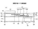
図4は発電手段117の組立斜視図、図5は発電手段117の断面図、図6は発電手段117の分解斜視図を示す。[Power generation means 117]
4 is an assembled perspective view of the power generation means 117, FIG. 5 is a sectional view of the power generation means 117, and FIG. 6 is an exploded perspective view of the power generation means 117.
発電手段117は、装置本体に働く加速度に応じて発電を行い、蓄電手段116に電力を蓄積するものであり、回転錘121、増速歯車機構122、弾み車123、発電機124、図示されていない整流平滑回路125から構成されている。 The power generation means 117 generates electric power according to the acceleration acting on the apparatus main body, and accumulates electric power in the power storage means 116. The
回転錘131は、略半円形状の金属板から構成され、円形状としたときの中心となる部分が回転軸141を中心に回転自在に保持されており、装置に働く加速度に応じて回転する。なお、回転錘131の形状は、半円形状に限定されるものではなく、回転軸141から偏移した位置に重心があるような構成であればよい。 The rotating weight 131 is made of a substantially semicircular metal plate, and a central portion when the circular shape is formed is rotatably held around a
増速歯車機構122は、第1歯車151a、第2歯車151b、第3歯車151c、第4歯車151dから構成されている。第1歯車151aは、回転軸141に固定されており、回転錘131の回転に応じて回転される。第2歯車151bは、段歯車から構成されており、回転軸142に固定され、小歯車が第1歯車151aに噛合しており、第1歯車151aの回転を増速する。第3歯車151cは、段歯車から構成されており、回転軸143に固定され、小歯車が第2歯車151bの大歯車に噛合しており、第2歯車151bの回転を増速する。第4歯車151dは、回転軸144に固定され、第3歯車151dの大歯車に噛合しており、第3歯車151cの回転を増速して、回転軸144を回転させる。 The speed increasing
増速歯車機構122により回転軸141の回転が増速された回転軸144に伝達される。回転軸141、142、143は、保持板161と保持板162との間に保持されている。保持板161と保持板162とは、スペーサ171を介して所定の間隔に保持されている。スペーサ171は、矢印Z1方向側の端部がネジ孔とされており、保持板161を挟んで、ネジ181がネジ止めされることにより、保持板161に保持されている。また、スペーサ171は、矢印Z2方向側の端部がネジとされており、保持板162を挟んで、スペーサ172の矢印Z1方向側端部に形成されたネジ孔に螺入されることにより、保持板162が保持されている。 The rotation of the
弾み車123は、発電機124の入力軸144に固定されており、発電機124の入力軸144の回転を維持する。 The
発電機124は、保持板163を挟んでネジ191を螺入することにより、保持板163に固定されている。保持板162と保持板163とは、スペーサ172により所定の間隔に保持されている。スペーサ172は、矢印Z1方向側の端部がネジ孔とされており、保持板162を挟んで、スペーサ171の矢印Z2方向側の端部に形成されたネジが螺入され、保持板162に保持される。また、スペーサ172は、矢印Z2方向側の端部がネジとされており、保持板163を挟んで、ネジをナット201に螺入させることにより、保持板163に保持される。 The
発電機124は、例えば、入力軸144の回転に応じてロータに巻回された巻線が回転し、周囲に配置された永久磁石により発生する磁束と鎖交することにより巻線に起電力が発生し、巻線に発生した起電力により発電が行なわれる。発電機124で発電された電力は、整流平滑回路125に供給される。 In the
整流平滑回路125は、発電機124から供給された電圧を整流、平滑化して直流電圧として出力する。整流平滑回路125で整流平滑化された直流電圧は、蓄電手段116に印加される。整流平滑回路125から供給された直流電圧によって蓄電手段116に電力を蓄積する。 The rectifying /
〔第1変形例〕
図7は発電機124の変形例の斜視図を示す。同図中、図3〜図6と同一構成部分には同一符号を付し、その説明は省略する。[First Modification]
FIG. 7 shows a perspective view of a modification of the
本変形例の発電機224は、磁石231、ヨーク232、コイル233から構成されている。 The
磁石231は、発電機224の入力回転軸144に、回転軸144に直交する方向に磁束が発生するように回転軸114を軸として回転可能に固定されている。ヨーク232は、高透磁率の磁性板を積層した構成とされており、その平面形状は略四角形となるように形成され、さらに、その一つの辺の一部が欠落した形状とされている。ヨーク232は、欠落した部分の端面232a、232bで磁石231を挟むように配置されており、磁石231の磁束により磁気回路が構成される。コイル233は、ヨーク232に巻回されており、その両端にヨーク232を貫通しており、回転する磁石231によって発生する磁束の変化に応じた電圧が発生する。コイル233の両端は、整流平滑回路125に接続されており、コイル233に発生した電圧は、整流平滑回路125により整流平滑化され、蓄電手段116に電力を蓄積させる。 The
〔第2変形例〕
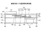
図8は発電手段117の変形例の組立斜視図、図9は発電手段117の変形例の断面図、図10は発電手段117の変形例の分解斜視図を示す。同図中、図3乃至図6と同一構成部分には同一符号を付し、その説明は省略する。[Second Modification]
8 is an assembly perspective view of a modification of the power generation means 117, FIG. 9 is a cross-sectional view of the modification of the power generation means 117, and FIG. 10 is an exploded perspective view of the modification of the power generation means 117. In the figure, the same components as those in FIGS. 3 to 6 are denoted by the same reference numerals, and the description thereof is omitted.
本実施例の発電手段317は、回転軸141と増速歯車機構122を構成する第1歯車151aとの間にワンウェイクラッチ機構321を設けた構成とされている。ワンウェイクラッチ機構321は、回転軸141の回転が増速歯車機構122の第1歯車151aの回転より速いときには回転軸141の回転を第1歯車151aに伝達し、回転軸141の回転が増速歯車機構122の第1歯車51aの回転より遅くなると、回転軸141の回転が第1歯車151aに対して空回りして、回転軸141の回転が第1歯車151aに伝達されないように働く。これによって、弾み車123の回転が回転錘121の回転に左右されることがなくなり、安定して回転を行なうことができる。 The power generation means 317 of the present embodiment is configured such that a one-way
〔第3変形例〕
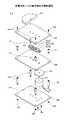
図11は発電手段117の他の変形例の組立斜視図、図12は発電手段117の他の変形例の断面図、図13は発電手段117の他の変形例の分解斜視図を示す。同図中、図3、図4、図5と同一構成部分には同一符号を付し、その説明は省略する。[Third Modification]
11 is an assembled perspective view of another modification of the power generation means 117, FIG. 12 is a cross-sectional view of another modification of the power generation means 117, and FIG. 13 is an exploded perspective view of another modification of the power generation means 117. In the figure, the same components as those in FIGS. 3, 4, and 5 are denoted by the same reference numerals, and the description thereof is omitted.
本実施例の発電手段417は、増速歯車機構122を構成する第4歯車51dと発電機124の入力軸である回転軸144との間にワンウェイクラッチ機構421を設けた構成とされている。ワンウェイクラッチ機構421は、増速歯車機構122の第4歯車151dの回転が回転軸144の回転より速いときには第4歯車151dの回転を回転軸144に伝達し、増速歯車機構122の第4歯車151dの回転が回転軸144の回転より遅くなると、第4歯車151dが回転軸144に対して空回りして、第4歯車151dの回転が回転軸144に伝達されないように働く。これによって、弾み車123の回転が回転錘121の回転に左右されることがなくなり、安定して回転を行なうことができる。 The power generation means 417 of the present embodiment is configured such that a one-way
1 システム
10 入力装置、20 通信ユニット、30、50 接続ケーブル
40 コンピュータ装置、60 ディスプレイ
111 座標入力手段、112 入力手段、113 処理手段、114 通信手段
115 電源生成手段、116 蓄電手段、117 発電手段、118 ケース
119 上カバー、120 下カバー
121 回転錘、122 増速歯車機構、123 弾み車、124 発電機
125 整流平滑回路
DESCRIPTION OF
Claims (8)
Translated fromJapanese前記本体に働く加速度に応じて発電を行なう発電手段と、
前記発電手段で発電された電力を蓄える蓄電手段と、
前記発電手段で発電された電力又は前記蓄電手段に蓄えられた電力により前記入力手段を駆動する電源を生成する電源生成手段とを有することを特徴とする入力装置。In an input device having input means for detecting acceleration acting on the main body and outputting a detection signal corresponding to the detected acceleration,
Power generation means for generating power according to the acceleration acting on the main body;
Power storage means for storing the power generated by the power generation means;
An input device comprising: a power generation unit configured to generate a power source for driving the input unit using the power generated by the power generation unit or the power stored in the power storage unit.
前記回転錘の回転軸に接続され、前記回転錘の回転数を増速させた回転数で出力軸を回転させる増速歯車機構と、
前記増速歯車機構の前記出力軸に接続され、前記出力軸の回転に応じて発電を行なう発電機とを有することを特徴とする請求項1記載の入力装置。The power generation means includes a rotating weight that rotates according to the acceleration,
A speed increasing gear mechanism that is connected to a rotating shaft of the rotating weight and rotates the output shaft at a rotating speed obtained by increasing the rotating speed of the rotating weight;
The input device according to claim 1, further comprising: a generator that is connected to the output shaft of the speed increasing gear mechanism and generates electric power in accordance with rotation of the output shaft.
前記回転錘の回転速度が前記弾み車の回転速度より速いときには、前記回転錘から前記弾み車に回転力を伝達し、前記回転錘の回転速度が前記弾み車の回転速度より遅くなったときには、前記回転錘から前記弾み車への回転力の伝達を解除する伝達手段とを有することを特徴とする請求項2記載の入力装置。The power generation means is rotated according to the rotational force of the rotating weight, and a spinning wheel that maintains the rotation of the input shaft of the speed increasing gear mechanism;
When the rotation speed of the rotating weight is higher than the rotation speed of the spinning wheel, a rotational force is transmitted from the rotating weight to the spinning wheel, and when the rotation speed of the rotating weight becomes lower than the rotation speed of the spinning wheel, the rotating weight The input device according to claim 2, further comprising: a transmission unit that cancels transmission of a rotational force from the to the spinning wheel.
前記増速歯車機構の回転速度が前記弾み車の回転速度より速いときには、前記増速歯車機構から前記弾み車に回転力を伝達し、前記増速歯車機構の回転速度が前記弾み車の回転速度より遅くなったときには、前記増速歯車機構から前記弾み車への回転力の伝達を解除する伝達手段とを有することを特徴とする請求項2記載の入力装置。The power generation means is rotated in accordance with the rotational force of the output shaft of the speed increasing gear mechanism, and maintains a rotation of the input shaft of the generator;
When the rotational speed of the speed increasing gear mechanism is higher than the rotational speed of the spinning wheel, the rotational speed is transmitted from the speed increasing gear mechanism to the spinning wheel, and the rotational speed of the speed increasing gear mechanism becomes slower than the rotational speed of the speed wheel. 3. An input device according to claim 2, further comprising a transmission means for releasing transmission of rotational force from the speed increasing gear mechanism to the spinning wheel.
両端面が前記磁石を挟んで対向して設けられ、前記磁石からの磁束により閉じた磁気回路を構成する磁性材と、
前記磁性材に巻回されて、前記磁性材を貫通する磁束に応じた電力を取り出すコイルとを有することを特徴とする請求項2乃至4のいずれか一項記載の入力装置。The power generation means includes a magnet that rotates according to the rotation of the output shaft of the speed increasing gear mechanism,
Both end faces are provided opposite to each other with the magnet interposed therebetween, and a magnetic material constituting a magnetic circuit closed by a magnetic flux from the magnet,
5. The input device according to claim 2, further comprising a coil that is wound around the magnetic material and extracts electric power corresponding to a magnetic flux penetrating the magnetic material. 6.
The input device according to claim 1, wherein the power generation unit includes a booster circuit that boosts a voltage from the power storage unit to a predetermined voltage.
Priority Applications (2)
| Application Number | Priority Date | Filing Date | Title |
|---|---|---|---|
| JP2004306917AJP2006119893A (en) | 2004-10-21 | 2004-10-21 | Input device |
| US11/048,827US7583254B2 (en) | 2004-10-21 | 2005-02-03 | Input device including power generating device |
Applications Claiming Priority (1)
| Application Number | Priority Date | Filing Date | Title |
|---|---|---|---|
| JP2004306917AJP2006119893A (en) | 2004-10-21 | 2004-10-21 | Input device |
Publications (1)
| Publication Number | Publication Date |
|---|---|
| JP2006119893Atrue JP2006119893A (en) | 2006-05-11 |
Family
ID=36205769
Family Applications (1)
| Application Number | Title | Priority Date | Filing Date |
|---|---|---|---|
| JP2004306917APendingJP2006119893A (en) | 2004-10-21 | 2004-10-21 | Input device |
Country Status (2)
| Country | Link |
|---|---|
| US (1) | US7583254B2 (en) |
| JP (1) | JP2006119893A (en) |
Cited By (3)
| Publication number | Priority date | Publication date | Assignee | Title |
|---|---|---|---|---|
| US8120575B2 (en) | 2007-08-28 | 2012-02-21 | Industrial Technology Research Institute | Interactive pointing device |
| JP2012104130A (en)* | 2010-03-31 | 2012-05-31 | Toshiba Corp | Communication system, communication apparatus, and method of supplying electric power |
| JPWO2015146806A1 (en)* | 2014-03-28 | 2017-04-13 | シチズン時計株式会社 | Power generation device and portable electric device |
Families Citing this family (8)
| Publication number | Priority date | Publication date | Assignee | Title |
|---|---|---|---|---|
| US7330923B2 (en)* | 2005-03-21 | 2008-02-12 | Avago Technologies Ecbu Ip (Singapore) Pte. Ltd. | Input devices and methods of operating same |
| US20070188453A1 (en)* | 2006-02-15 | 2007-08-16 | Logitech Europe S.A. | Input device roller with hybrid magnetic ratchet system |
| TW200923719A (en)* | 2007-11-19 | 2009-06-01 | Asustek Comp Inc | Input apparatus and optical mouse for computer and operation method thereof |
| CN101634909A (en)* | 2008-07-25 | 2010-01-27 | 鸿富锦精密工业(深圳)有限公司 | wireless mouse |
| CN101853092A (en)* | 2009-04-03 | 2010-10-06 | 鸿富锦精密工业(深圳)有限公司 | mouse |
| TW201126383A (en)* | 2010-01-20 | 2011-08-01 | Kye Systems Corp | Radio-frequency mouse |
| CN104765474A (en)* | 2014-01-03 | 2015-07-08 | 富泰华工业(深圳)有限公司 | Cordless mouse |
| US10975449B2 (en) | 2018-05-11 | 2021-04-13 | J. C K. Industries, Inc. | Mud gun cap |
Family Cites Families (15)
| Publication number | Priority date | Publication date | Assignee | Title |
|---|---|---|---|---|
| JPH0659810A (en) | 1992-08-06 | 1994-03-04 | Matsushita Electric Ind Co Ltd | Wireless mouse device |
| JP3006593B2 (en)* | 1997-09-30 | 2000-02-07 | セイコーエプソン株式会社 | Electronically controlled mechanical timepiece and control method thereof |
| US6137479A (en)* | 1997-12-05 | 2000-10-24 | Timex Corporation | Programmable computer pointing device |
| JPH11183645A (en)* | 1997-12-18 | 1999-07-09 | Seiko Instruments Inc | Self-winding watch |
| JP2001125722A (en) | 1999-11-01 | 2001-05-11 | Sharp Corp | Remote control device |
| US6686903B1 (en)* | 2000-07-28 | 2004-02-03 | Silitek Corporation | Wireless mouse capable of generating and accumulating electrical energy |
| JP2002132440A (en) | 2000-10-26 | 2002-05-10 | Nec Corp | Wireless aerial mouse |
| JP4689812B2 (en)* | 2000-11-17 | 2011-05-25 | 富士通コンポーネント株式会社 | Wireless mouse |
| US6903725B2 (en)* | 2001-02-23 | 2005-06-07 | Sabatino Nacson | Self-powered cordless mouse |
| US6933933B2 (en)* | 2001-10-02 | 2005-08-23 | Harris Corporation | Pen cartridge that transmits acceleration signal for recreating handwritten signatures and communications |
| US20030080938A1 (en)* | 2001-10-25 | 2003-05-01 | Bin Lian | Self-powered wireless device |
| US20030142065A1 (en)* | 2002-01-28 | 2003-07-31 | Kourosh Pahlavan | Ring pointer device with inertial sensors |
| JP3596548B2 (en)* | 2002-03-27 | 2004-12-02 | セイコーエプソン株式会社 | Electronic watches and electronic equipment |
| US7158116B2 (en)* | 2003-04-04 | 2007-01-02 | Drb Institute Llc | Rechargeable cordless input and pointing device |
| US7554167B2 (en)* | 2003-12-29 | 2009-06-30 | Vladimir Vaganov | Three-dimensional analog input control device |
- 2004
- 2004-10-21JPJP2004306917Apatent/JP2006119893A/enactivePending
- 2005
- 2005-02-03USUS11/048,827patent/US7583254B2/ennot_activeExpired - Fee Related
Cited By (4)
| Publication number | Priority date | Publication date | Assignee | Title |
|---|---|---|---|---|
| US8120575B2 (en) | 2007-08-28 | 2012-02-21 | Industrial Technology Research Institute | Interactive pointing device |
| JP2012104130A (en)* | 2010-03-31 | 2012-05-31 | Toshiba Corp | Communication system, communication apparatus, and method of supplying electric power |
| JPWO2015146806A1 (en)* | 2014-03-28 | 2017-04-13 | シチズン時計株式会社 | Power generation device and portable electric device |
| US10566913B2 (en) | 2014-03-28 | 2020-02-18 | Citizen Watch Co., Ltd. | Power generation device and portable electric device |
Also Published As
| Publication number | Publication date |
|---|---|
| US7583254B2 (en) | 2009-09-01 |
| US20060087494A1 (en) | 2006-04-27 |
Similar Documents
| Publication | Publication Date | Title |
|---|---|---|
| KR101138575B1 (en) | Energy harvesting based on user-interface of mobile computing device | |
| JP2006119893A (en) | Input device | |
| US20100271340A1 (en) | Rotary Input Device and Electronic Equipment | |
| US9958968B2 (en) | Input and output operation device | |
| US20060284842A1 (en) | Rechargeable Cordless Input and Pointing Device | |
| JP6252720B2 (en) | Distribution system, distribution method, and program | |
| JP2017182118A (en) | Electronic pen and position detection system | |
| EP3086201B1 (en) | Electronic device and display method thereof | |
| JP6241036B2 (en) | Communication terminal, position management system, and communication method | |
| CN112953037A (en) | Electronic device and charging control method | |
| JP2008263742A (en) | Motor unit | |
| JP2006340453A (en) | Wireless mouse | |
| JP2006106917A (en) | Wireless unit for drive shaft, lid for bearing cup grease injection hole, and drive shaft monitoring system | |
| JPH0926836A (en) | Portable I / O device | |
| WO2018230359A1 (en) | Power generation switch | |
| JPH10283079A (en) | Pointer input device | |
| WO2018230360A1 (en) | Power generation device | |
| EP2360812B1 (en) | Navigation tool including induction functionality | |
| US20190072930A1 (en) | Control apparatus | |
| WO2021205553A1 (en) | Operation device and operation system | |
| CN218675995U (en) | Navigation operation device, input control device and ultrasonic imaging system | |
| JP4254207B2 (en) | Power generation device and electronic device having this power generation device | |
| JP6956248B2 (en) | Electronic pen and position detection system | |
| EP4066369B1 (en) | Multifunctional haptic actuator | |
| JP6814898B2 (en) | Electronic pen and position detection system |