JP2006116356A - Surgical suturing apparatus with loading mechanism - Google Patents
Surgical suturing apparatus with loading mechanismDownload PDFInfo
- Publication number
- JP2006116356A JP2006116356AJP2006019811AJP2006019811AJP2006116356AJP 2006116356 AJP2006116356 AJP 2006116356AJP 2006019811 AJP2006019811 AJP 2006019811AJP 2006019811 AJP2006019811 AJP 2006019811AJP 2006116356 AJP2006116356 AJP 2006116356A
- Authority
- JP
- Japan
- Prior art keywords
- needle
- jaw
- surgical
- jaws
- jaw elements
- Prior art date
- Legal status (The legal status is an assumption and is not a legal conclusion. Google has not performed a legal analysis and makes no representation as to the accuracy of the status listed.)
- Withdrawn
Links
Images


Classifications
- A—HUMAN NECESSITIES
- A61—MEDICAL OR VETERINARY SCIENCE; HYGIENE
- A61B—DIAGNOSIS; SURGERY; IDENTIFICATION
- A61B17/00—Surgical instruments, devices or methods
- A61B17/28—Surgical forceps
- A61B17/29—Forceps for use in minimally invasive surgery
- A61B17/2909—Handles
- A—HUMAN NECESSITIES
- A61—MEDICAL OR VETERINARY SCIENCE; HYGIENE
- A61B—DIAGNOSIS; SURGERY; IDENTIFICATION
- A61B17/00—Surgical instruments, devices or methods
- A61B17/04—Surgical instruments, devices or methods for suturing wounds; Holders or packages for needles or suture materials
- A61B17/0469—Suturing instruments for use in minimally invasive surgery, e.g. endoscopic surgery
- A—HUMAN NECESSITIES
- A61—MEDICAL OR VETERINARY SCIENCE; HYGIENE
- A61B—DIAGNOSIS; SURGERY; IDENTIFICATION
- A61B17/00—Surgical instruments, devices or methods
- A61B17/04—Surgical instruments, devices or methods for suturing wounds; Holders or packages for needles or suture materials
- A61B17/06—Needles ; Sutures; Needle-suture combinations; Holders or packages for needles or suture materials
- A61B17/062—Needle manipulators
- A61B17/0625—Needle manipulators the needle being specially adapted to interact with the manipulator, e.g. being ridged to snap fit in a hole of the manipulator
- A—HUMAN NECESSITIES
- A61—MEDICAL OR VETERINARY SCIENCE; HYGIENE
- A61B—DIAGNOSIS; SURGERY; IDENTIFICATION
- A61B17/00—Surgical instruments, devices or methods
- A61B17/04—Surgical instruments, devices or methods for suturing wounds; Holders or packages for needles or suture materials
- A61B17/0401—Suture anchors, buttons or pledgets, i.e. means for attaching sutures to bone, cartilage or soft tissue; Instruments for applying or removing suture anchors
- A—HUMAN NECESSITIES
- A61—MEDICAL OR VETERINARY SCIENCE; HYGIENE
- A61B—DIAGNOSIS; SURGERY; IDENTIFICATION
- A61B17/00—Surgical instruments, devices or methods
- A61B17/04—Surgical instruments, devices or methods for suturing wounds; Holders or packages for needles or suture materials
- A61B17/0491—Sewing machines for surgery
- A—HUMAN NECESSITIES
- A61—MEDICAL OR VETERINARY SCIENCE; HYGIENE
- A61B—DIAGNOSIS; SURGERY; IDENTIFICATION
- A61B17/00—Surgical instruments, devices or methods
- A61B17/04—Surgical instruments, devices or methods for suturing wounds; Holders or packages for needles or suture materials
- A61B17/06—Needles ; Sutures; Needle-suture combinations; Holders or packages for needles or suture materials
- A61B17/06114—Packages or dispensers for needles or sutures
- A—HUMAN NECESSITIES
- A61—MEDICAL OR VETERINARY SCIENCE; HYGIENE
- A61B—DIAGNOSIS; SURGERY; IDENTIFICATION
- A61B17/00—Surgical instruments, devices or methods
- A61B17/04—Surgical instruments, devices or methods for suturing wounds; Holders or packages for needles or suture materials
- A61B17/0469—Suturing instruments for use in minimally invasive surgery, e.g. endoscopic surgery
- A61B2017/0479—Packages or dispensers for MIS suturing instruments
- A—HUMAN NECESSITIES
- A61—MEDICAL OR VETERINARY SCIENCE; HYGIENE
- A61B—DIAGNOSIS; SURGERY; IDENTIFICATION
- A61B17/00—Surgical instruments, devices or methods
- A61B17/04—Surgical instruments, devices or methods for suturing wounds; Holders or packages for needles or suture materials
- A61B17/06—Needles ; Sutures; Needle-suture combinations; Holders or packages for needles or suture materials
- A61B17/06004—Means for attaching suture to needle
- A61B2017/06019—Means for attaching suture to needle by means of a suture-receiving lateral eyelet machined in the needle
- A—HUMAN NECESSITIES
- A61—MEDICAL OR VETERINARY SCIENCE; HYGIENE
- A61B—DIAGNOSIS; SURGERY; IDENTIFICATION
- A61B17/00—Surgical instruments, devices or methods
- A61B17/04—Surgical instruments, devices or methods for suturing wounds; Holders or packages for needles or suture materials
- A61B17/06—Needles ; Sutures; Needle-suture combinations; Holders or packages for needles or suture materials
- A61B17/06004—Means for attaching suture to needle
- A61B2017/06033—Means for attaching suture to needle using adhesives
- A—HUMAN NECESSITIES
- A61—MEDICAL OR VETERINARY SCIENCE; HYGIENE
- A61B—DIAGNOSIS; SURGERY; IDENTIFICATION
- A61B17/00—Surgical instruments, devices or methods
- A61B17/04—Surgical instruments, devices or methods for suturing wounds; Holders or packages for needles or suture materials
- A61B17/06—Needles ; Sutures; Needle-suture combinations; Holders or packages for needles or suture materials
- A61B17/06004—Means for attaching suture to needle
- A61B2017/06047—Means for attaching suture to needle located at the middle of the needle
- A—HUMAN NECESSITIES
- A61—MEDICAL OR VETERINARY SCIENCE; HYGIENE
- A61B—DIAGNOSIS; SURGERY; IDENTIFICATION
- A61B17/00—Surgical instruments, devices or methods
- A61B17/04—Surgical instruments, devices or methods for suturing wounds; Holders or packages for needles or suture materials
- A61B17/06—Needles ; Sutures; Needle-suture combinations; Holders or packages for needles or suture materials
- A61B17/06066—Needles, e.g. needle tip configurations
- A61B2017/06085—Needles, e.g. needle tip configurations having a blunt tip
- A—HUMAN NECESSITIES
- A61—MEDICAL OR VETERINARY SCIENCE; HYGIENE
- A61B—DIAGNOSIS; SURGERY; IDENTIFICATION
- A61B17/00—Surgical instruments, devices or methods
- A61B17/04—Surgical instruments, devices or methods for suturing wounds; Holders or packages for needles or suture materials
- A61B17/06—Needles ; Sutures; Needle-suture combinations; Holders or packages for needles or suture materials
- A61B17/06066—Needles, e.g. needle tip configurations
- A61B2017/0609—Needles, e.g. needle tip configurations having sharp tips at both ends, e.g. shuttle needle alternately retained and released by first and second facing jaws of a suturing instrument
- A—HUMAN NECESSITIES
- A61—MEDICAL OR VETERINARY SCIENCE; HYGIENE
- A61B—DIAGNOSIS; SURGERY; IDENTIFICATION
- A61B17/00—Surgical instruments, devices or methods
- A61B17/28—Surgical forceps
- A61B17/29—Forceps for use in minimally invasive surgery
- A61B17/2909—Handles
- A61B2017/2912—Handles transmission of forces to actuating rod or piston
- A61B2017/2919—Handles transmission of forces to actuating rod or piston details of linkages or pivot points
- A61B2017/292—Handles transmission of forces to actuating rod or piston details of linkages or pivot points connection of actuating rod to handle, e.g. ball end in recess
- A—HUMAN NECESSITIES
- A61—MEDICAL OR VETERINARY SCIENCE; HYGIENE
- A61B—DIAGNOSIS; SURGERY; IDENTIFICATION
- A61B17/00—Surgical instruments, devices or methods
- A61B17/28—Surgical forceps
- A61B17/29—Forceps for use in minimally invasive surgery
- A61B2017/2926—Details of heads or jaws
- A61B2017/2932—Transmission of forces to jaw members
- A61B2017/2933—Transmission of forces to jaw members camming or guiding means
- A61B2017/2936—Pins in guiding slots
Landscapes
- Health & Medical Sciences (AREA)
- Life Sciences & Earth Sciences (AREA)
- Surgery (AREA)
- Molecular Biology (AREA)
- General Health & Medical Sciences (AREA)
- Biomedical Technology (AREA)
- Heart & Thoracic Surgery (AREA)
- Medical Informatics (AREA)
- Nuclear Medicine, Radiotherapy & Molecular Imaging (AREA)
- Animal Behavior & Ethology (AREA)
- Engineering & Computer Science (AREA)
- Public Health (AREA)
- Veterinary Medicine (AREA)
- Ophthalmology & Optometry (AREA)
- Surgical Instruments (AREA)
- Prostheses (AREA)
- External Artificial Organs (AREA)
- Materials For Medical Uses (AREA)
Abstract
Description
Translated fromJapanese本発明は、広くは手術器具に関し、より詳しくは、内視鏡手術又は腹腔鏡手術に使用できる縫合装置に関する。 The present invention relates generally to surgical instruments, and more particularly to a suturing device that can be used for endoscopic or laparoscopic surgery.
内視鏡手術又は腹腔鏡手術は、手元側端部及び先端側端部をもつ比較的小径の長いカニューレ構造を用いることを特徴とする。先端側端部は、周囲の組織を通って、手術又は検査すべき体腔内に導かれ、これにより手術器具を挿入するための導管を形成する。所与の手術中に、同時に種々の器具の操作ができるようにするため、複数のカニューレ構造を使用できる。例えば、一方のカニューレが手術体腔内の視覚及び照明用内視鏡のための導管を形成し、一方、他方のカニューレが特定手術機能を遂行するように設計された特殊手術器具の制御のための導管を形成することもできる。 Endoscopic surgery or laparoscopic surgery is characterized by using a relatively small diameter long cannula structure having a proximal end and a distal end. The distal end is guided through the surrounding tissue into the body cavity to be operated on or examined, thereby forming a conduit for insertion of a surgical instrument. Multiple cannula structures can be used to allow simultaneous manipulation of various instruments during a given operation. For example, one cannula forms a conduit for vision and illumination endoscopes within a surgical body cavity, while the other cannula is used to control special surgical instruments designed to perform specific surgical functions. A conduit can also be formed.
多くの手術は組織を通って縫合することを必要とし、このような手術は伝統的に手で行われている。腹腔鏡縫合は、一般に平均5〜7cmのポートを通して行わなければならないため、特に挑戦的な仕事である。腹腔鏡縫合を容易にする1つの器具が、1993年4月28日付公開に係る英国特許出願第2260704号(特許文献1)に記載されている。上記英国特許出願に記載された縫合装置は腹腔鏡縫合を行うのに使用できるけれども、ひとたび縫合糸を使い果たすか、新しい針を必要とする場合には、縫合装置を手で再装填しなければならず、これは非常に時間のかかることである。吻合を行う場合、一般に、2〜3筋の縫合を行って強化するのが好ましいと考えられているため、
上記英国特許出願に記載の腹腔鏡縫合装置は、1回以上の手による再装填を必要とする。新しい針及び縫合糸の迅速且つ効率的な再装填を可能にする腹腔鏡縫合器具を提供することは有効である。また、腹腔鏡縫合装置は、針がいずれのジョーにも固定されていない場合にはジョーが移動できないようにして、体腔内で針が不意に外れることを防止する装置が有効である。
The laparoscopic suturing device described in the above UK patent application requires one or more manual reloads. It would be advantageous to provide a laparoscopic suturing instrument that allows for quick and efficient reloading of new needles and sutures. In addition, the laparoscopic suturing device is effective as a device that prevents the needle from moving unexpectedly in the body cavity by preventing the jaw from moving when the needle is not fixed to any jaw.
従って、本発明の目的は、従来技術の縫合装置に付随する欠点を解消する手術用縫合装置を提供することにある。本発明の他の目的は、内視鏡手術及び腹腔鏡手術に使用できる手術用縫合装置を提供することにある。本発明の更に他の目的は、縫合を行うべき体腔内に配備できる手術用縫合装置を提供することにある。 Accordingly, it is an object of the present invention to provide a surgical suturing device that overcomes the disadvantages associated with prior art suturing devices. Another object of the present invention is to provide a surgical suturing apparatus that can be used for endoscopic surgery and laparoscopic surgery. Still another object of the present invention is to provide a surgical suturing device that can be deployed in a body cavity to be sutured.
簡単にいえば、本発明は、長い本体部分と、該本体部分から延びた2つのジョーエレメントと、針(又は同様な手術用切開部材)を固定するための固定手段とを有し、該固定手段が各ジョーエレメントの第1凹部と協働し、固定手段により固定された針を解放するための、固定手段と協働する解放手段を更に有する手術装置を提供することにある。また、ジョーからの針の不意の脱落防止を補助すべく、ジョーエレメントが開くことを防止するための、前記固定手段と協働するロッキング手段が提供される。本発明の装置はまた、ロッキング手段を無効にして、新しい針及び縫合糸を装置に装填できるようにする無効機構を有する。この装置には、針及び縫合糸の交換を更に容易にするための装填機構も考えられる。 Briefly, the present invention comprises a long body portion, two jaw elements extending from the body portion, and a securing means for securing a needle (or similar surgical incision member). It is an object of the present invention to provide a surgical device further comprising a release means cooperating with the securing means for the means cooperating with the first recess of each jaw element to release the needle secured by the securing means. Also, locking means is provided that cooperates with the securing means to prevent the jaw elements from opening to help prevent the needle from unintentionally falling off the jaws. The device of the present invention also has a disabling mechanism that disables the locking means so that a new needle and suture can be loaded into the device. The device also contemplates a loading mechanism to further facilitate needle and suture replacement.
より特定すれば、本発明は、以下に関する。 More specifically, the present invention relates to the following.
(1)手術用切開部材を操作するための手術装置において、長い本体部分と、この本体部分から延びた第1及び第2ジョーエレメントとを有し、このジョーエレメントの少なくとも一方が開放位置と閉鎖位置との間で移動でき、このジョーエレメントと協働する手術用切開部材と、この手術用切開部材の一部を、上記ジョーエレメントに固定するための固定手段と、上記ジョーエレメントを制御するためのハンドルとを有し、このハンドルがジョーエレメントと同じ平面内で移動でき、上記手術用切開部材が上記ジョーエレメントの一方に固定されていない場合に、上記少なくとも一方のジョーエレメントが開放位置に移動することを防止するためのロッキング機構を更に有することを特徴とする手術装置。 (1) In a surgical apparatus for operating a surgical incision member, it has a long main body portion and first and second jaw elements extending from the main body portion, and at least one of the jaw elements is in an open position and a closed position. A surgical incision member which can be moved between positions and cooperates with the jaw element, fixing means for securing a part of the surgical incision member to the jaw element, and for controlling the jaw element The handle is movable in the same plane as the jaw element, and when the surgical incision member is not fixed to one of the jaw elements, the at least one jaw element moves to the open position. A surgical apparatus further comprising a locking mechanism for preventing the operation.
(2)上記固定手段が第1位置と第2位置との間で移動でき、上記ロッキング機構が、上記固定手段が前記第2位置にあるときにロックされることを特徴とする項目(1)に記載の手術装置。 (2) Item (1) characterized in that the fixing means can move between a first position and a second position, and the locking mechanism is locked when the fixing means is in the second position. The surgical apparatus according to 1.
(3)上記手術用切開部材の一部が上記ジョーエレメントのいずれにも固定されていない場合に、上記ジョーエレメントが開き得るようにするための無効機構を更に有することを特徴とする項目(1)又は(2)に記載の手術装置。 (3) The item (1) further comprising a disabling mechanism for allowing the jaw element to open when a part of the surgical incision member is not fixed to any of the jaw elements. ) Or the surgical device according to (2).
(4)本体部分と、手術用切開部材の一部を保持するための保持手段と、上記手術用切開部材の一部を受け入れるように上記ジョーエレメントを位置決めする受け入れ手段とからなる装填機構を更に有することを特徴とする項目(1)〜(3)のいずれかに記載の手術装置。 (4) A loading mechanism further comprising a main body portion, a holding means for holding a part of the surgical incising member, and a receiving means for positioning the jaw element so as to receive a part of the surgical incising member. The surgical apparatus according to any one of items (1) to (3), comprising:
(5)上記手術用切開部材の一部が、両端部が尖った針を備え、この針の両端部が上記固定手段と協働する構造及び寸法を有することを特徴とする項目(1)〜(4)のいずれかに記載の手術装置。 (5) Items (1) to (5), wherein a part of the surgical incision member includes a needle with sharpened both ends, and the both ends of the needle have a structure and dimensions that cooperate with the fixing means. The surgical apparatus according to any one of (4).
(6)上記固定手段が、上記記手術用切開部材と協働する構造及び寸法を有する摺動可能なブレードを備えていることを特徴とする項目(1)〜(5)のいずれかに記載の手術装置。 (6) The fixing means includes a slidable blade having a structure and dimensions that cooperate with the surgical incision member, according to any one of items (1) to (5). Surgical device.
(7)上記ハンドルが、上記本体部分に対し回転可能に取り付けられていることを特徴とする項目(1)〜(6)のいずれかに記載の手術装置。 (7) The surgical device according to any one of items (1) to (6), wherein the handle is rotatably attached to the main body portion.
(8)上記ジョーエレメントの各々が、上記手術用切開部材を受け入れるための第1凹部を備えていることを特徴とする項目(1)〜(7)のいずれかに記載の手術装置。 (8) The surgical device according to any one of items (1) to (7), wherein each of the jaw elements includes a first recess for receiving the surgical incision member.
(9)上記固定手段により固定された上記手術用切開部材の一部を解放させるための、上記固定手段と協働する解放手段を更に有することを特徴とする項目(1)〜(8)のいずれかに記載の手術装置。 (9) The item (1) to (8), further comprising release means for cooperating with the fixing means for releasing a part of the surgical incision member fixed by the fixing means. The surgical apparatus in any one.
本発明の手術用切開部材を操作するための手術装置は、長い本体部分と、この本体部分から延びた第1及び第2ジョーエレメントとを有し、このジョーエレメントの少なくとも一方が開放位置と閉鎖位置との間で移動でき、このジョーエレメントと協働する手術用切開部材と、この手術用切開部材の一部を、上記ジョーエレメントに固定するための固定手段と、上記ジョーエレメントを制御するためのハンドルとを有し、このハンドルがジョーエレメントと同じ平面内で移動でき、上記手術用切開部材が上記ジョーエレメントの一方に固定されていない場合に、上記少なくとも一方のジョーエレメントが開放位置に移動することを防止するためのロッキング機構を更に有するので、手術用切開部材がいずれのシジョーにも固定されていない場合には、ジョーが移動できないようにして、体腔内で針が不意に外れることを防止する。 A surgical apparatus for operating a surgical incision member of the present invention has a long main body portion and first and second jaw elements extending from the main body portion, and at least one of the jaw elements is in an open position and a closed position. A surgical incision member which can be moved between positions and cooperates with the jaw element, fixing means for securing a part of the surgical incision member to the jaw element, and for controlling the jaw element The handle is movable in the same plane as the jaw element, and when the surgical incision member is not fixed to one of the jaw elements, the at least one jaw element moves to the open position. If the surgical incision member is not fixed to any of the jaws, it has a locking mechanism to prevent , The jaws so as not to move the needle in the body cavity can be prevented from deviating unexpectedly.
上記及び他の目的及び長所は、以下に明らかになるであるが、本発明の一部を構成する添付図面を参照してより完全に説明し且つ特許請求する詳細な構成及び作動にある。尚、添付図面の全体を通じて、同一参照番号は同類の部品を示す。 These and other objects and advantages will become apparent in the following detailed description and operation which is more fully described and claimed with reference to the accompanying drawings which form a part of the present invention. Throughout the attached drawings, the same reference numerals indicate similar parts.
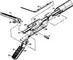
図面、特に図1には、本発明の一実施例による縫合装置が示されている。縫合装置(その全体を参照番号1で示す)はハンドルハウジング61を有し、該ハンドルハウジング61は、2アーム形ハンドル2と、長い管状ハウジングすなわち本体部分3と、2つのジョー(すなわちジョーエレメント)4、5とを備えている。ハンドル2は両ジョー4、5の開閉を制御するのに使用され且つ人間工学的利益を得るため両ジョー4、5と同じ平面内で移動するように設計できる。また、ハンドル2は、別の人間工学的利益を得るため、本体部分3に対し回転可能に連結することもできる。管状ハウジング3は、例えば5mm又は10mmの内径をもつ管状カニューレ構造を通して配備できる好ましい寸法を有するので、この実施例は、内視鏡手術又は腹腔鏡手術での使用に特に適している。 In the drawing, in particular in FIG. 1, a suturing device according to an embodiment of the invention is shown. The suturing device (shown in its entirety by reference numeral 1) has a handle housing 61 which comprises a two-armed handle 2, a long tubular housing or body portion 3 and two jaws (ie jaw elements). 4 and 5. The handle 2 is used to control the opening and closing of both jaws 4, 5 and can be designed to move in the same plane as both jaws 4, 5 for ergonomic benefit. The handle 2 can also be rotatably connected to the main body part 3 for another ergonomic benefit. This embodiment is particularly suitable for use in endoscopic or laparoscopic surgery, as the tubular housing 3 has preferred dimensions that can be deployed through a tubular cannula structure, for example having an inner diameter of 5 mm or 10 mm.
図2に示すように、ハンドル2は、1対のリンク33、34及びピン49、50、51によりロッド7に連結される。中央のロッド7は、ばね6により先端側方向に付勢されている。ばね6は中央ロッド7の回りに嵌合され且つハウジング61のチャンネル63内に配置される。ハンドル2を握ると、中央ロッド7が後方(手元側)に移動し、ばね6が圧縮される。 As shown in FIG. 2, the handle 2 is connected to the rod 7 by a pair of links 33, 34 and pins 49, 50, 51. The central rod 7 is urged toward the distal end side by a spring 6. The spring 6 is fitted around the central rod 7 and is arranged in the channel 63 of the housing 61. When the handle 2 is gripped, the central rod 7 moves rearward (hand side), and the spring 6 is compressed.
図3に示すように、中央ロッド7の先端側端部には、各ジョー4、5のカムスロット9、10に通されるピン8が設けられている。ジョー4、5は、孔12、13及びサポート52の孔53、54に通されるピン11により互いに枢着される。中央ロッド7が後方に引っ張られると、ピン8もカムスロット9、10内で後方に引っ張られ、両ジョー4、5を閉じるカム作用をする。 As shown in FIG. 3, a pin 8 that is passed through the cam slots 9, 10 of the jaws 4, 5 is provided at the end of the central rod 7 on the front end side. The jaws 4 and 5 are pivotally attached to each other by pins 11 that pass through the holes 12 and 13 and the
図3に示すように、各ジョーは、その凹部15内に針14(図7)を受け入れるようになっている。両ジョー4、5が図5に示すように閉じられると、針14が両ジョーの凹部15内に配置される。両ジョーが開かれると、針14は、ブレード16又は29のいずれが針14の凹部17(図8)と交差するかに基づいて、いずれか一方の凹部15内に保持される。 As shown in FIG. 3, each jaw is adapted to receive a needle 14 (FIG. 7) in its recess 15. When both jaws 4 and 5 are closed as shown in FIG. 5, the
図4に示すように、例えば上方のジョーエレメント4と協働するブレード16が、凹部17内に延入して針14を固定する。或いは、ブレード29が凹部17を通って針14と交差し、針14をジョー5に固定することもできる。針14と係合するブレード16、29の運動は、後で詳細に説明する。 As shown in FIG. 4, for example, a
側方ロッド21、22が、中央ロッド7の両側で管状ハウジング3内に配置され且つ側方ロッド21、22の手元側端部はハンドルハウジング61内に移動可能に収容されたホイール23に連結される。ハウジング61の両半部は、ピン30により固定される。ホイール23は、この両側から突出した2つのアーム24、25を有し、該アーム24、25は、装置のオペレータがホイール23を回転できるようにする。針14をジョー4からジョー5に移すには、両ジョーを閉じ且つ側方アーム25を時計回り方向に回転することによりホイール23を回転させて、側方ロッド21を後方に引っ張り且つ側方ロッド22を前方に押し出す。側方ロッド21、22は、それぞれ、ブレード16、29に連結されている。従って、側方ロッド21が前方に押し出されると、ブレード29が前方に押し出されて針14の凹部17内に延入することにより針14と係合し、該針14をジョー5に固定する。ブレード29が前方位置にある間、ブレード16は後退位置にあり、従って、ブレード16は針14とは接触せず、このためジョー4から針14を解放できる。同様に、側方アーム24を反時計回り方向に回転して、側方ロッド21及びブレード16を前方に且つ側方アーム22及びブレード29を後方に摺動させ、これにより、針14をジョー4に固定し且つジョー5から解放することができる。ブレード16、29の先端側端部には、それぞれ、ノッチ40、41が設けられている。これらのノッチは、後述の無効機構が付勢されない限り、ジョー4、5の凹部15の後方(手元側)に維持される。無効機構が付勢されると、ノッチ40、41は凹部15と整合する。
次に、ブレード16又は29が針14を固定する位置に移動していない限り両ジョー4、5が開くことを防止するロックアウト機構について説明すると、図2に示すように、ピン28が、手元側がホイール23内に収容されるロッド7を通って延びている。ホイール23は、ノッチ26、27及びこれらのノッチ間の衝合面65を有する。ピン28がノッチ26、27のうちの一方の口部と整合するようにホイール23が位置決めされると、ピン28が前方に移動してノッチ内に入り得る余地を有するため、両ジョー4、5を開くことができる。これに対し、ピン28が衝合面65に当接する位置にあると、ピン28が衝合面65により停止される(すなわち、前方に移動する余地がない)ため、両ジョー4、5を開くことはできない。 Next, a lockout mechanism for preventing the jaws 4 and 5 from opening unless the
図4に示す初期位置では、ジョー4、5と同様にハンドル2が開いている。針14は、ブレード16によりジョー4内に保持されている。この位置では、ピン28がノッチ27内に前進している。両ジョー4、5を閉じて身体組織を縫合するには、ハンドル2を一緒に握り、ピン28がノッチ27の口部に位置するようにロッド7及びこれに関連するピン28を後方に移動させる。次に、アーム24又は25を用いてホイール23を回転させ、前述のように針14をジョー4からジョー5に通す。これでハンドルを緩めると、ピン28が(前述の)ばね6の力により前方に移動してノッチ26内に入り、従ってロッド7が前方に移動して両ジョーを開く。 In the initial position shown in FIG. 4, the handle 2 is opened like the jaws 4 and 5. The
従って、ピン28がノッチ26と整合するようにホイール23が位置決めされると、側方ロッド22が前方位置に押し出され、この前方位置でブレード29が凹部17を通って針14と交差し、これにより針14がジョー5に固定される。ピン28がノッチ27と整合するようにホイール23が位置決めされると、側方アーム21が前方位置に押し出され、この前方位置でブレード16が凹部17を通って針14と交差し、これにより針14がジョー4に固定される。 Accordingly, when the
ピン28がいずれのノッチの口部とも整合していないとき(すなわち、ピン28が衝合面65に当接(衝合面65と整合)するようにホイール23が位置決めされているとき)に、使用者がハンドル2を緩めることを試みても、ピン28は前方に摺動できず、従って両ジョー4、5を開くべくロッド7が前方に摺動することはできない。かくして、本発明のロッキング機構は、針14がそれぞれのブレードによっていずれか一方のジョーに固定されていなければ、両ジョー4、5が開くことを防止する。 When the
針14は、図7に示すように湾曲し、両尖端部55、56を有し、且つその中央部が手術用縫合糸18の一部に連結されている。チャンネル66が縫合糸の一端を保持する。縫合糸を針内に保持するには、縫合糸をチャンネル66内に接着してもよいし、或いは針自体をかしめてもよい。図8に示すような真直針を使用して、縫合糸を針の一端に隣接して連結することもできる(図示せず)。或いは、一端が尖った針を使用することもできる(図示せず)。縫合糸18の反対側端部には、組織に縫合糸を固定するためのアンカー19を設けることもできる。 The
図10、図11及び図12に示すように、本発明の縫合装置を操作するには、開いたジョー4、5が、縫合すべき組織の回りに配置される。針14は、ブレード16によりジョー4に固定的に保持された状態が示されていることに留意すべきである。ハンドル2を握ると、組織の回りで両ジョー4、5が閉じられ、ブレード16によりジョー4に固定的に保持された針14が組織を突き刺す。針14が組織を突き刺すと、針14は反対側のジョー5の凹部15内に案内される。ジョーが開かれているとき、ピン28は前述のようにノッチ26又は27内の前方位置に配置されている。従って、ジョーが閉じられ且つピン28が衝合面65に沿って移動できるようになるまでホイール23は移動できない。ジョーを閉じると、側方アーム25を時計回り方向に回転させることによりホイール23を移動でき、これにより、ブレード16が摺動されて針14の一端から外れ、同時にブレード29が摺動されて針の他端に入る。この時計回り方向の移動により、ピン28は、前述のようにノッチ27の口部からノッチ26の口部へと摺動する。かくして、側方アーム25(及びホイール23)を回転させることにより、針14がジョー4から解放され且つジョー5と係合する。次に、針14がジョー5に配置され、組織を通して縫合糸18を引き出す。アンカー19は組織上に載り、これにより組織中に縫合糸18を固定する。次に、ハンドルを緩めることにより、両ジョー4、5が開かれる。針14が両尖端形(両端が尖っている針)の場合には、器具は、次の縫合ができる準備が整った状態になる。次の縫合を行うには、ハンドル2を握り、両ジョーを再び閉じる。第2の縫合を行うべくジョーを閉じた後、ホイール23の側方アーム24を回転してブレード16を先端側に且つブレード29を手元側に摺動させることにより、針14をジョー4に戻すことができる。針が一尖端形(一端のみが尖っている針)の場合には、次の縫合を行うべく器具を準備する前に、(両ジョーを閉じ且つホイール23を回転することにより)針を反対側のジョーに戻さなくてはならない。 As shown in FIGS. 10, 11 and 12, to operate the suturing device of the present invention, open jaws 4, 5 are placed around the tissue to be sutured. It should be noted that the
縫合装置を装填するには、両ジョー4、5を開き、針14を取り外しできるようにし且つ交換針をスロット15内に装填できるようにしなければならない。これは、上記固定機構に従って、いずれかのブレード16又は29がスロット15と交差している場合には行うことはできない。従って、図2及び図14に示すように、上記ロックアウト機構を無効にする機構が設けられている。U形チャンネル35及びホイール23の手元側で、ハウジング61のチャンネル64内には、ばね34が収容される。ロッド7は、ばね34、U形チャンネル35の孔59及びホイール23を通って配置される。各プランジャ36、37がホイール23の両側の孔60内に配置され、各プランジャはU形チャンネル35に通される。各プランジャ36、37はスプリングワッシャ46上に載置され、該スプリングワッシャ46もホイール23の孔60内に配置される。プランジャ36、37は、それぞれ、これらのプランジャから延び且つハウジング61に通される小径のノブ38、39を有する。 To load the suturing device, both jaws 4, 5 must be opened so that the
図2及び図14に示すように、ハウジング61はチャンネル62を有し、該チャンネル62内で、ノブ38、39がそれぞれ自由に前後に移動できる。しかしながら、プランジャ36、37は、ハウジング61の表面48に当接する。ノブ38、39が押し下げられると、スプリングワッシャ46は、プランジャ36、37を押圧して表面48を通過させ且つ圧縮されたばね34のエネルギによって押し出されて凹部47内へと前方(先端側方向)に移動する。 As shown in FIGS. 2 and 14, the housing 61 has a channel 62 in which the knobs 38 and 39 can freely move back and forth. However, the
従って、この無効機構を作動させるには、ピン28が衝合面65に当接してノッチ26又は27内に前進できなくなるように側方アーム24、25を位置決めする。ノブ38、39が押し下げられ、これにより、ホイール23がハウジング61の凹部47内へと前進される。ホイール23が前進すると、ピン28及びロッド7も前進し、これにより両ジョー4、5が開かれる。 Therefore, to activate this ineffective mechanism, the
上記のようにホイール23が前方に押し出されると、ノッチ40、41が各ジョーの凹部15と整合するように、側方ロッド21、22及びブレード16、29が充分前方に駆動される。ノッチ40、41が凹部15と整合するとき、ブレード16、29は技術的に前方位置を占める(この前方位置は両ジョーを開くことができるようにする。なぜならば、上記ロックアウト機構は、いずれのブレードも前方位置にないときにのみ作動するからである。)。しかしながら、この位置では、凹部15は、ブレード16、29と交差するのではなく、ノッチ40、41と整合しており、これにより、凹部15は各ジョーの全開度に亘って邪魔がなくなり、これにより、古い針14を器具から取り外して、新しい針14と交換できるようになる。かくして、上記ロックアウト機構は無効機構によって無効にされたことになる。なぜならば、両ジョー4、5が開かれており且つその上針14が固定されていないからである。新しい針が挿入されたならば、側方アーム24、25を手元側に引っ張り、ばね34を圧縮し、下方のノブ36、37と表面48とを再係合させることができ、これにより、この器具のロックアウト機構の機能回復がなされる。 When the
針、縫合糸及びアンカーを交換するための図13に示す本発明の装填機構を参照すると、針14はノッチ44内に配置され且つ装填機構の凹部42、43はジョー4、5を受け入れるように構成されている。両ジョー4、5が閉じられると、針14がジョー4内に係合し、且つ閉じられた両ジョーは、凹部49を介して両ジョーを持ち上げることにより装填機構から取り外される。この装填機構の本体部分45は中空にして、これにより、縫合糸を収容するパッケージ及びアンカーをこの中に保持するように構成できる。 Referring to the loading mechanism of the present invention shown in FIG. 13 for exchanging needles, sutures and anchors, the
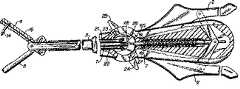
図6は、針、縫合糸及びアンカーを交換するための本発明の装填機構33の別の実施例を示す。この装填機構は、ハンドル30と、固定具57、58を介してハンドル30に取り付けられるアーム31、32とからなる。各アームは、アンカー/位置決めエレメント19又は針14を保持するようになっている。両アーム31、32を同じ寸法にするため、アンカー/位置決めエレメント19及び針14はほぼ同じ直径にするのが好ましい。 FIG. 6 shows another embodiment of the loading mechanism 33 of the present invention for exchanging needles, sutures and anchors. The loading mechanism includes a handle 30 and
図9に示すように、各ジョーは、図6に示すアンカー19を保持するように構成できる。凹部20は、縫合糸アンカーの保持に適した1つの用例である。針の凹部15とアンカーの凹部20との間の距離は、適正な装填を容易にするため、装填機構の針14とアンカー19との間の距離にほぼ等しい。縫合糸アンカー19は、縫合糸18により針14に固定的に取り付けることができる。また、縫合糸アンカー19は、凹部15内への針14の案内及び配置を補助する。アンカー19が凹部20内に適正に配置されない場合には、両ジョー4、5を閉じることはできない。しかしながら、アンカー19が適正に配置されると、凹部15内への針14の配置の案内を補助する。或いは、別の位置決めエレメントを設けることができる。更に別の実施例では、位置決めエレメント19が、装填機構33に固定的に取り付けられ且つ位置決めの目的で凹部20内に配置されるけれども、装填機構33を縫合装置から取り外すときには引き離されるように構成できる。 As shown in FIG. 9, each jaw can be configured to hold an
アンカー及び縫合糸を装置に再装填するには、前述の無効機構を付勢し、古い針を取り外す。図9に示すように、装填機構33を用いて装置を再装填するには、装填機構33を、開放した底ジョー5に対して垂直に保持し、且つ針14及びアンカー/位置決めエレメント19をそれぞれの凹部15、20内に同時に配置する。針14及びアンカー/位置決めエレメント19がこれらのそれぞれの凹部内に配置されたならば、両ジョー4、5を閉じ且つ装填機構33を引き離して、針14及びアンカー19を所定位置に残す。 To reload the device with anchors and sutures, the aforementioned disabling mechanism is activated and the old needle is removed. As shown in FIG. 9, to reload the device using the loading mechanism 33, the loading mechanism 33 is held perpendicular to the open bottom jaw 5 and the
装填機構を用いるか否かに係わらず、ひとたび新しい針、縫合糸及びアンカーが両ジョー4、5に装填されると、前述のように、ノブ38、39を手元側に引っ張ってプランジャ36、37とハウジング61の表面48とを再係合させることにより、ロックアウト機構の機能回復を行わなくてはならない。この場合、ホイール23を回転して、ブレード16又は29が針14と交差するように該ブレードを前方位置に配置し、これにより、ジョー4、5が開かれたときに針14を保持し、器具が組織の次の部分を突き刺すことができるようにしなければならない。 Regardless of whether or not a loading mechanism is used, once new needles, sutures, and anchors are loaded into both jaws 4, 5, the
上記説明は、本発明の原理のみを示すものと考えるべきである。また、本発明は、ここに示し且つ説明した正確な構造及び作動に限定されるものではない。従って、あらゆる適当な変更及び均等物は、本発明の範囲内に含まれるものである。 The above description should be considered as illustrative only of the principles of the invention. In addition, the present invention is not limited to the precise construction and operation shown and described herein. Accordingly, all suitable modifications and equivalents are intended to be included within the scope of the present invention.
内視鏡手術または腹腔鏡手術に使用され、新しい針及び縫合糸の迅速且つ効率的な再装填を可能にする腹腔鏡縫合器具が提供される。 A laparoscopic suturing instrument is provided that is used for endoscopic or laparoscopic surgery and allows for quick and efficient reloading of new needles and sutures.
1縫合装置
2ハンドル
4ジョー
5ジョー
6ばね
7中央ロッド
14針
15凹部
16ブレード
21側方ロッド
22側方ロッド
23ホイール
24側方アーム
25側方アーム
26ノッチ
27ノッチ
28ピン
29ブレード
34ばね
36プランジャ
37プランジャ
38ノブ
39ノブ
45装填機構の本体部分
46スプリングワッシャ
61ハウジング
65衝合面1 Suture device 2 Handle 4 Jaw 5 Jaw 6 Spring 7
Claims (1)
Translated fromJapanese長い本体部分と、
該本体部分から延びた第1及び第2ジョーエレメントとを有し、該ジョーエレメントの少なくとも一方が開放位置と閉鎖位置との間で移動でき、
該ジョーエレメントと協働する手術用切開部材と、
該手術用切開部材の一部を、前記ジョーエレメントに固定するための固定手段と、
前記ジョーエレメントを制御するためのハンドルとを有し、該ハンドルがジョーエレメントと同じ平面内で移動でき、
前記手術用切開部材が前記ジョーエレメントの一方に固定されていない場合に、前記少なくとも一方のジョーエレメントが開放位置に移動することを防止するためのロッキング機構を更に有することを特徴とする手術装置。In a surgical apparatus for operating a surgical incision member,
A long body part,
First and second jaw elements extending from the body portion, at least one of the jaw elements being movable between an open position and a closed position;
A surgical incision member cooperating with the jaw element;
Fixing means for fixing a part of the surgical incising member to the jaw element;
A handle for controlling the jaw element, the handle being movable in the same plane as the jaw element;
A surgical apparatus further comprising a locking mechanism for preventing the at least one jaw element from moving to an open position when the surgical incision member is not fixed to one of the jaw elements.
Applications Claiming Priority (1)
| Application Number | Priority Date | Filing Date | Title |
|---|---|---|---|
| US13414593A | 1993-10-08 | 1993-10-08 |
Related Parent Applications (1)
| Application Number | Title | Priority Date | Filing Date |
|---|---|---|---|
| JP2003354084ADivisionJP3792687B2 (en) | 1993-10-08 | 2003-10-14 | Surgical suture device having a loading mechanism |
Publications (1)
| Publication Number | Publication Date |
|---|---|
| JP2006116356Atrue JP2006116356A (en) | 2006-05-11 |
Family
ID=22461975
Family Applications (3)
| Application Number | Title | Priority Date | Filing Date |
|---|---|---|---|
| JP24537494AExpired - Fee RelatedJP3662609B2 (en) | 1993-10-08 | 1994-10-11 | Surgical suturing device with loading mechanism |
| JP2003354084AExpired - Fee RelatedJP3792687B2 (en) | 1993-10-08 | 2003-10-14 | Surgical suture device having a loading mechanism |
| JP2006019811AWithdrawnJP2006116356A (en) | 1993-10-08 | 2006-01-27 | Surgical suturing apparatus with loading mechanism |
Family Applications Before (2)
| Application Number | Title | Priority Date | Filing Date |
|---|---|---|---|
| JP24537494AExpired - Fee RelatedJP3662609B2 (en) | 1993-10-08 | 1994-10-11 | Surgical suturing device with loading mechanism |
| JP2003354084AExpired - Fee RelatedJP3792687B2 (en) | 1993-10-08 | 2003-10-14 | Surgical suture device having a loading mechanism |
Country Status (8)
| Country | Link |
|---|---|
| US (2) | US5674229A (en) |
| EP (3) | EP0647431B1 (en) |
| JP (3) | JP3662609B2 (en) |
| AT (1) | ATE221753T1 (en) |
| AU (2) | AU697965B2 (en) |
| CA (1) | CA2133377C (en) |
| DE (3) | DE69434677T2 (en) |
| ES (3) | ES2185528T3 (en) |
Cited By (4)
| Publication number | Priority date | Publication date | Assignee | Title |
|---|---|---|---|---|
| WO2010053118A1 (en)* | 2008-11-06 | 2010-05-14 | オリンパスメディカルシステムズ株式会社 | Suture device and suture system |
| WO2014129554A1 (en)* | 2013-02-22 | 2014-08-28 | 住友ベークライト株式会社 | Repeating-type organ-fastening tool |
| JP2014183879A (en)* | 2013-03-22 | 2014-10-02 | Sumitomo Bakelite Co Ltd | Repeating-type organ fixture |
| WO2016104991A1 (en)* | 2014-12-26 | 2016-06-30 | 국립암센터 | Suturing device for surgery |
Families Citing this family (321)
| Publication number | Priority date | Publication date | Assignee | Title |
|---|---|---|---|---|
| GB9306080D0 (en)* | 1993-03-24 | 1993-05-12 | Smith James R | Surgical needle holder |
| US5569301A (en) | 1993-10-08 | 1996-10-29 | United States Surgical Corporation | Surgical incision members for endoscopic suturing apparatus |
| US5478344A (en)* | 1993-10-08 | 1995-12-26 | United States Surgical Corporation | Surgical suturing apparatus with loading mechanism |
| US5478345A (en)* | 1994-08-19 | 1995-12-26 | United States Surgical Corporation | Mechanism for endoscopic suturing device |
| US5480406A (en)* | 1994-10-07 | 1996-01-02 | United States Surgical Corporation | Method of employing surgical suturing apparatus to tie knots |
| US5571090A (en)* | 1994-10-07 | 1996-11-05 | United States Surgical Corporation | Vascular suturing apparatus |
| US5938668A (en)* | 1994-10-07 | 1999-08-17 | United States Surgical | Surgical suturing apparatus |
| CA2157744C (en)* | 1994-10-07 | 2005-08-23 | Charles R. Sherts | Endoscopic vascular suturing apparatus |
| CA2186077C (en)* | 1995-09-22 | 2006-08-01 | Charles R. Sherts | Vascular suturing apparatus |
| US5667528A (en)* | 1995-11-22 | 1997-09-16 | United States Surgical Corporation | Braided suture surgical incision member attachment |
| US5733293A (en)* | 1996-05-08 | 1998-03-31 | United States Surgical Corporation | Disposable loading unit for a vascular suturing instrument |
| US6126666A (en)* | 1997-04-14 | 2000-10-03 | Forschungszcutrum Karlsruhe Gmbh | Device for inserting a surgical suture needle into an endoscopic suture apparatus |
| US5908428A (en)* | 1997-05-27 | 1999-06-01 | United States Surgical Corporation | Stitching devices for heart valve replacement surgery |
| US6231565B1 (en) | 1997-06-18 | 2001-05-15 | United States Surgical Corporation | Robotic arm DLUs for performing surgical tasks |
| US7435249B2 (en) | 1997-11-12 | 2008-10-14 | Covidien Ag | Electrosurgical instruments which reduces collateral damage to adjacent tissue |
| US6726686B2 (en) | 1997-11-12 | 2004-04-27 | Sherwood Services Ag | Bipolar electrosurgical instrument for sealing vessels |
| US6228083B1 (en) | 1997-11-14 | 2001-05-08 | Sherwood Services Ag | Laparoscopic bipolar electrosurgical instrument |
| US7582087B2 (en) | 1998-10-23 | 2009-09-01 | Covidien Ag | Vessel sealing instrument |
| US7267677B2 (en) | 1998-10-23 | 2007-09-11 | Sherwood Services Ag | Vessel sealing instrument |
| US7118570B2 (en) | 2001-04-06 | 2006-10-10 | Sherwood Services Ag | Vessel sealing forceps with disposable electrodes |
| US7364577B2 (en) | 2002-02-11 | 2008-04-29 | Sherwood Services Ag | Vessel sealing system |
| US6299624B1 (en)* | 1999-05-27 | 2001-10-09 | Karl Storz Gmbh & Co. Kg | Handle for a medical instrument |
| US20030109875A1 (en) | 1999-10-22 | 2003-06-12 | Tetzlaff Philip M. | Open vessel sealing forceps with disposable electrodes |
| US6821282B2 (en)* | 2000-11-27 | 2004-11-23 | Scimed Life Systems, Inc. | Full thickness resection device control handle |
| EP2000106B1 (en) | 2001-02-08 | 2010-06-09 | Tyco Healthcare Group Lp | Ultrasonic surgical instrument |
| ATE415869T1 (en)* | 2001-03-23 | 2008-12-15 | Arthrex Inc | INSTRUMENT FOR PULLING A THREAD DURING ARTHROSCOPIC SEWING OF TISSUE |
| ES2262639T3 (en) | 2001-04-06 | 2006-12-01 | Sherwood Services Ag | SHUTTER AND DIVIDER OF GLASSES WITH BUMPER MEMBERS N OCONDUCTIVES. |
| EP1527747B1 (en) | 2001-04-06 | 2015-09-30 | Covidien AG | Electrosurgical instrument which reduces collateral damage to adjacent tissue |
| US7615059B2 (en)* | 2001-05-30 | 2009-11-10 | Ams Research Corporation | Surgical suture passers and methods |
| US7104949B2 (en)* | 2001-08-31 | 2006-09-12 | Ams Research Corporation | Surgical articles for placing an implant about a tubular tissue structure and methods |
| US7879046B2 (en)* | 2001-10-01 | 2011-02-01 | Depuy Mitek, Inc. | Suturing apparatus and method |
| EP2392265B2 (en)* | 2001-10-01 | 2017-04-26 | DePuy Mitek, Inc. | Suturing apparatus |
| US7464847B2 (en) | 2005-06-03 | 2008-12-16 | Tyco Healthcare Group Lp | Surgical stapler with timer and feedback display |
| US10285694B2 (en) | 2001-10-20 | 2019-05-14 | Covidien Lp | Surgical stapler with timer and feedback display |
| US7530985B2 (en) | 2002-01-30 | 2009-05-12 | Olympus Corporation | Endoscopic suturing system |
| US7344545B2 (en) | 2002-01-30 | 2008-03-18 | Olympus Corporation | Endoscopic suturing system |
| US7618425B2 (en)* | 2002-01-30 | 2009-11-17 | Olympus Corporation | Endoscopic suturing system |
| WO2003090630A2 (en) | 2002-04-25 | 2003-11-06 | Tyco Healthcare Group, Lp | Surgical instruments including micro-electromechanical systems (mems) |
| US6984237B2 (en) | 2002-05-22 | 2006-01-10 | Orthopaedic Biosystems Ltd., Inc. | Suture passing surgical instrument |
| US7270664B2 (en) | 2002-10-04 | 2007-09-18 | Sherwood Services Ag | Vessel sealing instrument with electrical cutting mechanism |
| US7931649B2 (en) | 2002-10-04 | 2011-04-26 | Tyco Healthcare Group Lp | Vessel sealing instrument with electrical cutting mechanism |
| US7276068B2 (en) | 2002-10-04 | 2007-10-02 | Sherwood Services Ag | Vessel sealing instrument with electrical cutting mechanism |
| US7799026B2 (en) | 2002-11-14 | 2010-09-21 | Covidien Ag | Compressible jaw configuration with bipolar RF output electrodes for soft tissue fusion |
| EP1601298B1 (en) | 2003-03-13 | 2016-09-07 | Covidien AG | Bipolar concentric electrode assembly for soft tissue fusion |
| CA2523675C (en) | 2003-05-01 | 2016-04-26 | Sherwood Services Ag | Electrosurgical instrument which reduces thermal damage to adjacent tissue |
| US7160299B2 (en) | 2003-05-01 | 2007-01-09 | Sherwood Services Ag | Method of fusing biomaterials with radiofrequency energy |
| AU2003243219B2 (en) | 2003-05-09 | 2009-10-29 | Covidien Lp | Anastomotic staple with fluid dispensing capillary |
| JP5137230B2 (en) | 2003-05-15 | 2013-02-06 | コヴィディエン・アクチェンゲゼルシャフト | Tissue sealer with non-conductive variable stop member and method for sealing tissue |
| US7156846B2 (en) | 2003-06-13 | 2007-01-02 | Sherwood Services Ag | Vessel sealer and divider for use with small trocars and cannulas |
| US7857812B2 (en) | 2003-06-13 | 2010-12-28 | Covidien Ag | Vessel sealer and divider having elongated knife stroke and safety for cutting mechanism |
| US7150749B2 (en) | 2003-06-13 | 2006-12-19 | Sherwood Services Ag | Vessel sealer and divider having elongated knife stroke and safety cutting mechanism |
| USD956973S1 (en) | 2003-06-13 | 2022-07-05 | Covidien Ag | Movable handle for endoscopic vessel sealer and divider |
| US9848938B2 (en) | 2003-11-13 | 2017-12-26 | Covidien Ag | Compressible jaw configuration with bipolar RF output electrodes for soft tissue fusion |
| US7367976B2 (en) | 2003-11-17 | 2008-05-06 | Sherwood Services Ag | Bipolar forceps having monopolar extension |
| US7131970B2 (en) | 2003-11-19 | 2006-11-07 | Sherwood Services Ag | Open vessel sealing instrument with cutting mechanism |
| US7811283B2 (en) | 2003-11-19 | 2010-10-12 | Covidien Ag | Open vessel sealing instrument with hourglass cutting mechanism and over-ratchet safety |
| US7500975B2 (en) | 2003-11-19 | 2009-03-10 | Covidien Ag | Spring loaded reciprocating tissue cutting mechanism in a forceps-style electrosurgical instrument |
| US7442193B2 (en) | 2003-11-20 | 2008-10-28 | Covidien Ag | Electrically conductive/insulative over-shoe for tissue fusion |
| CN100490750C (en)* | 2004-01-23 | 2009-05-27 | Ams研究公司 | Tissue Binding and Cutting Tools |
| US7608092B1 (en) | 2004-02-20 | 2009-10-27 | Biomet Sports Medicince, LLC | Method and apparatus for performing meniscus repair |
| US7780662B2 (en) | 2004-03-02 | 2010-08-24 | Covidien Ag | Vessel sealing system using capacitive RF dielectric heating |
| EP1755461B1 (en) | 2004-06-16 | 2014-01-01 | Smith & Nephew, Inc. | Suture passing device |
| US7195631B2 (en) | 2004-09-09 | 2007-03-27 | Sherwood Services Ag | Forceps with spring loaded end effector assembly |
| US7540872B2 (en) | 2004-09-21 | 2009-06-02 | Covidien Ag | Articulating bipolar electrosurgical instrument |
| US7955332B2 (en) | 2004-10-08 | 2011-06-07 | Covidien Ag | Mechanism for dividing tissue in a hemostat-style instrument |
| US7909851B2 (en) | 2006-02-03 | 2011-03-22 | Biomet Sports Medicine, Llc | Soft tissue repair device and associated methods |
| US8361113B2 (en) | 2006-02-03 | 2013-01-29 | Biomet Sports Medicine, Llc | Method and apparatus for coupling soft tissue to a bone |
| US8088130B2 (en) | 2006-02-03 | 2012-01-03 | Biomet Sports Medicine, Llc | Method and apparatus for coupling soft tissue to a bone |
| US9017381B2 (en) | 2007-04-10 | 2015-04-28 | Biomet Sports Medicine, Llc | Adjustable knotless loops |
| US7857830B2 (en) | 2006-02-03 | 2010-12-28 | Biomet Sports Medicine, Llc | Soft tissue repair and conduit device |
| US20060189993A1 (en) | 2004-11-09 | 2006-08-24 | Arthrotek, Inc. | Soft tissue conduit device |
| US8128658B2 (en) | 2004-11-05 | 2012-03-06 | Biomet Sports Medicine, Llc | Method and apparatus for coupling soft tissue to bone |
| US7905903B2 (en) | 2006-02-03 | 2011-03-15 | Biomet Sports Medicine, Llc | Method for tissue fixation |
| US8118836B2 (en) | 2004-11-05 | 2012-02-21 | Biomet Sports Medicine, Llc | Method and apparatus for coupling soft tissue to a bone |
| US7658751B2 (en) | 2006-09-29 | 2010-02-09 | Biomet Sports Medicine, Llc | Method for implanting soft tissue |
| US7749250B2 (en) | 2006-02-03 | 2010-07-06 | Biomet Sports Medicine, Llc | Soft tissue repair assembly and associated method |
| US8298262B2 (en) | 2006-02-03 | 2012-10-30 | Biomet Sports Medicine, Llc | Method for tissue fixation |
| US7905904B2 (en) | 2006-02-03 | 2011-03-15 | Biomet Sports Medicine, Llc | Soft tissue repair device and associated methods |
| US8840645B2 (en) | 2004-11-05 | 2014-09-23 | Biomet Sports Medicine, Llc | Method and apparatus for coupling soft tissue to a bone |
| US9801708B2 (en) | 2004-11-05 | 2017-10-31 | Biomet Sports Medicine, Llc | Method and apparatus for coupling soft tissue to a bone |
| US8137382B2 (en) | 2004-11-05 | 2012-03-20 | Biomet Sports Medicine, Llc | Method and apparatus for coupling anatomical features |
| US8303604B2 (en) | 2004-11-05 | 2012-11-06 | Biomet Sports Medicine, Llc | Soft tissue repair device and method |
| US8998949B2 (en) | 2004-11-09 | 2015-04-07 | Biomet Sports Medicine, Llc | Soft tissue conduit device |
| US7686804B2 (en) | 2005-01-14 | 2010-03-30 | Covidien Ag | Vessel sealer and divider with rotating sealer and cutter |
| US7909823B2 (en) | 2005-01-14 | 2011-03-22 | Covidien Ag | Open vessel sealing instrument |
| US7491202B2 (en) | 2005-03-31 | 2009-02-17 | Covidien Ag | Electrosurgical forceps with slow closure sealing plates and method of sealing tissue |
| CA2609970C (en) | 2005-06-03 | 2014-08-12 | Tyco Healthcare Group Lp | Battery powered surgical instrument |
| US11291443B2 (en) | 2005-06-03 | 2022-04-05 | Covidien Lp | Surgical stapler with timer and feedback display |
| US7789878B2 (en) | 2005-09-30 | 2010-09-07 | Covidien Ag | In-line vessel sealer and divider |
| CA2561034C (en) | 2005-09-30 | 2014-12-09 | Sherwood Services Ag | Flexible endoscopic catheter with an end effector for coagulating and transfecting tissue |
| ES2381560T3 (en) | 2005-09-30 | 2012-05-29 | Covidien Ag | Insulating sleeve for electrosurgical forceps |
| US7879035B2 (en) | 2005-09-30 | 2011-02-01 | Covidien Ag | Insulating boot for electrosurgical forceps |
| US7722607B2 (en) | 2005-09-30 | 2010-05-25 | Covidien Ag | In-line vessel sealer and divider |
| US7922953B2 (en) | 2005-09-30 | 2011-04-12 | Covidien Ag | Method for manufacturing an end effector assembly |
| US8241282B2 (en) | 2006-01-24 | 2012-08-14 | Tyco Healthcare Group Lp | Vessel sealing cutting assemblies |
| US8882766B2 (en) | 2006-01-24 | 2014-11-11 | Covidien Ag | Method and system for controlling delivery of energy to divide tissue |
| US8734443B2 (en) | 2006-01-24 | 2014-05-27 | Covidien Lp | Vessel sealer and divider for large tissue structures |
| US8298232B2 (en) | 2006-01-24 | 2012-10-30 | Tyco Healthcare Group Lp | Endoscopic vessel sealer and divider for large tissue structures |
| US8562647B2 (en) | 2006-09-29 | 2013-10-22 | Biomet Sports Medicine, Llc | Method and apparatus for securing soft tissue to bone |
| US9271713B2 (en) | 2006-02-03 | 2016-03-01 | Biomet Sports Medicine, Llc | Method and apparatus for tensioning a suture |
| US9078644B2 (en) | 2006-09-29 | 2015-07-14 | Biomet Sports Medicine, Llc | Fracture fixation device |
| US8574235B2 (en) | 2006-02-03 | 2013-11-05 | Biomet Sports Medicine, Llc | Method for trochanteric reattachment |
| US8562645B2 (en) | 2006-09-29 | 2013-10-22 | Biomet Sports Medicine, Llc | Method and apparatus for forming a self-locking adjustable loop |
| US8771352B2 (en) | 2011-05-17 | 2014-07-08 | Biomet Sports Medicine, Llc | Method and apparatus for tibial fixation of an ACL graft |
| US8652171B2 (en) | 2006-02-03 | 2014-02-18 | Biomet Sports Medicine, Llc | Method and apparatus for soft tissue fixation |
| US9149267B2 (en) | 2006-02-03 | 2015-10-06 | Biomet Sports Medicine, Llc | Method and apparatus for coupling soft tissue to a bone |
| US8968364B2 (en) | 2006-02-03 | 2015-03-03 | Biomet Sports Medicine, Llc | Method and apparatus for fixation of an ACL graft |
| US8652172B2 (en) | 2006-02-03 | 2014-02-18 | Biomet Sports Medicine, Llc | Flexible anchors for tissue fixation |
| US7959650B2 (en) | 2006-09-29 | 2011-06-14 | Biomet Sports Medicine, Llc | Adjustable knotless loops |
| US9538998B2 (en) | 2006-02-03 | 2017-01-10 | Biomet Sports Medicine, Llc | Method and apparatus for fracture fixation |
| US8506597B2 (en) | 2011-10-25 | 2013-08-13 | Biomet Sports Medicine, Llc | Method and apparatus for interosseous membrane reconstruction |
| US11259792B2 (en) | 2006-02-03 | 2022-03-01 | Biomet Sports Medicine, Llc | Method and apparatus for coupling anatomical features |
| US8801783B2 (en) | 2006-09-29 | 2014-08-12 | Biomet Sports Medicine, Llc | Prosthetic ligament system for knee joint |
| US8597327B2 (en) | 2006-02-03 | 2013-12-03 | Biomet Manufacturing, Llc | Method and apparatus for sternal closure |
| US11311287B2 (en) | 2006-02-03 | 2022-04-26 | Biomet Sports Medicine, Llc | Method for tissue fixation |
| US9468433B2 (en) | 2006-02-03 | 2016-10-18 | Biomet Sports Medicine, Llc | Method and apparatus for forming a self-locking adjustable loop |
| US8251998B2 (en) | 2006-08-16 | 2012-08-28 | Biomet Sports Medicine, Llc | Chondral defect repair |
| US10517587B2 (en) | 2006-02-03 | 2019-12-31 | Biomet Sports Medicine, Llc | Method and apparatus for forming a self-locking adjustable loop |
| US20070213749A1 (en)* | 2006-03-08 | 2007-09-13 | Olympus Medical Systems Corp. | Medical procedure performed inside abdominal cavity |
| US10743862B1 (en) | 2006-05-04 | 2020-08-18 | Alfredo Alvarado | Laparoscopic suturing device and methods of use |
| US7776037B2 (en) | 2006-07-07 | 2010-08-17 | Covidien Ag | System and method for controlling electrode gap during tissue sealing |
| USD571914S1 (en)* | 2006-07-19 | 2008-06-24 | Karl Storz Gmbh & Co. Kg | Medical instrument |
| US8597297B2 (en) | 2006-08-29 | 2013-12-03 | Covidien Ag | Vessel sealing instrument with multiple electrode configurations |
| CN101662999B (en)* | 2006-09-28 | 2016-01-20 | 心叶科技公司 | Delivery tools for percutaneous delivery of prostheses |
| US9918826B2 (en) | 2006-09-29 | 2018-03-20 | Biomet Sports Medicine, Llc | Scaffold for spring ligament repair |
| US8672969B2 (en) | 2006-09-29 | 2014-03-18 | Biomet Sports Medicine, Llc | Fracture fixation device |
| US11259794B2 (en) | 2006-09-29 | 2022-03-01 | Biomet Sports Medicine, Llc | Method for implanting soft tissue |
| US8500818B2 (en) | 2006-09-29 | 2013-08-06 | Biomet Manufacturing, Llc | Knee prosthesis assembly with ligament link |
| US8070746B2 (en) | 2006-10-03 | 2011-12-06 | Tyco Healthcare Group Lp | Radiofrequency fusion of cardiac tissue |
| WO2008045374A2 (en)* | 2006-10-05 | 2008-04-17 | Tyco Healthcare Group Lp | Handle assembly for articulated endoscopic instruments |
| US8226667B2 (en) | 2006-10-05 | 2012-07-24 | Tyco Healthcare Group Lp | Axial stitching device |
| JP5481194B2 (en) | 2006-10-05 | 2014-04-23 | コヴィディエン リミテッド パートナーシップ | Flexible endoscopic suturing device |
| US8733614B2 (en) | 2006-10-06 | 2014-05-27 | Covidien Lp | End effector identification by mechanical features |
| JP5225996B2 (en) | 2006-10-06 | 2013-07-03 | タイコ ヘルスケア グループ リミテッド パートナーシップ | Endoscopic vessel sealer and divider with flexible articulation shaft |
| US8475453B2 (en) | 2006-10-06 | 2013-07-02 | Covidien Lp | Endoscopic vessel sealer and divider having a flexible articulating shaft |
| USD649249S1 (en) | 2007-02-15 | 2011-11-22 | Tyco Healthcare Group Lp | End effectors of an elongated dissecting and dividing instrument |
| US7431188B1 (en) | 2007-03-15 | 2008-10-07 | Tyco Healthcare Group Lp | Surgical stapling apparatus with powered articulation |
| US8267935B2 (en) | 2007-04-04 | 2012-09-18 | Tyco Healthcare Group Lp | Electrosurgical instrument reducing current densities at an insulator conductor junction |
| US8800837B2 (en) | 2007-04-13 | 2014-08-12 | Covidien Lp | Powered surgical instrument |
| US7950560B2 (en) | 2007-04-13 | 2011-05-31 | Tyco Healthcare Group Lp | Powered surgical instrument |
| US20080255413A1 (en) | 2007-04-13 | 2008-10-16 | Michael Zemlok | Powered surgical instrument |
| US11259801B2 (en) | 2007-04-13 | 2022-03-01 | Covidien Lp | Powered surgical instrument |
| US7823760B2 (en) | 2007-05-01 | 2010-11-02 | Tyco Healthcare Group Lp | Powered surgical stapling device platform |
| US7931660B2 (en) | 2007-05-10 | 2011-04-26 | Tyco Healthcare Group Lp | Powered tacker instrument |
| US9211119B2 (en) | 2007-07-03 | 2015-12-15 | Ceterix Orthopaedics, Inc. | Suture passers and methods of passing suture |
| US8500809B2 (en) | 2011-01-10 | 2013-08-06 | Ceterix Orthopaedics, Inc. | Implant and method for repair of the anterior cruciate ligament |
| US20100130990A1 (en)* | 2007-07-03 | 2010-05-27 | Saliman Justin D | Methods of suturing and repairing tissue using a continuous suture passer device |
| US8465505B2 (en) | 2011-05-06 | 2013-06-18 | Ceterix Orthopaedics, Inc. | Suture passer devices and methods |
| US20090012538A1 (en)* | 2007-07-03 | 2009-01-08 | Justin Saliman | Methods and devices for continuous suture passing |
| US8663253B2 (en) | 2007-07-03 | 2014-03-04 | Ceterix Orthopaedics, Inc. | Methods of meniscus repair |
| US20110130773A1 (en)* | 2007-07-03 | 2011-06-02 | Saliman Justin D | Methods for continuous suture passing |
| US9314234B2 (en) | 2007-07-03 | 2016-04-19 | Ceterix Orthopaedics, Inc. | Pre-tied surgical knots for use with suture passers |
| US8911456B2 (en) | 2007-07-03 | 2014-12-16 | Ceterix Orthopaedics, Inc. | Methods and devices for preventing tissue bridging while suturing |
| US8702731B2 (en) | 2007-07-03 | 2014-04-22 | Ceterix Orthopaedics, Inc. | Suturing and repairing tissue using in vivo suture loading |
| US10441273B2 (en) | 2007-07-03 | 2019-10-15 | Ceterix Orthopaedics, Inc. | Pre-tied surgical knots for use with suture passers |
| US9861354B2 (en) | 2011-05-06 | 2018-01-09 | Ceterix Orthopaedics, Inc. | Meniscus repair |
| US8821518B2 (en)* | 2007-11-05 | 2014-09-02 | Ceterix Orthopaedics, Inc. | Suture passing instrument and method |
| US9005238B2 (en)* | 2007-08-23 | 2015-04-14 | Covidien Lp | Endoscopic surgical devices |
| US8251996B2 (en) | 2007-09-28 | 2012-08-28 | Tyco Healthcare Group Lp | Insulating sheath for electrosurgical forceps |
| US8235993B2 (en) | 2007-09-28 | 2012-08-07 | Tyco Healthcare Group Lp | Insulating boot for electrosurgical forceps with exohinged structure |
| US8235992B2 (en) | 2007-09-28 | 2012-08-07 | Tyco Healthcare Group Lp | Insulating boot with mechanical reinforcement for electrosurgical forceps |
| US8221416B2 (en) | 2007-09-28 | 2012-07-17 | Tyco Healthcare Group Lp | Insulating boot for electrosurgical forceps with thermoplastic clevis |
| US9023043B2 (en) | 2007-09-28 | 2015-05-05 | Covidien Lp | Insulating mechanically-interfaced boot and jaws for electrosurgical forceps |
| AU2008221509B2 (en) | 2007-09-28 | 2013-10-10 | Covidien Lp | Dual durometer insulating boot for electrosurgical forceps |
| US8236025B2 (en) | 2007-09-28 | 2012-08-07 | Tyco Healthcare Group Lp | Silicone insulated electrosurgical forceps |
| US8267936B2 (en) | 2007-09-28 | 2012-09-18 | Tyco Healthcare Group Lp | Insulating mechanically-interfaced adhesive for electrosurgical forceps |
| US7922063B2 (en) | 2007-10-31 | 2011-04-12 | Tyco Healthcare Group, Lp | Powered surgical instrument |
| US8764748B2 (en) | 2008-02-06 | 2014-07-01 | Covidien Lp | End effector assembly for electrosurgical device and method for making the same |
| US8623276B2 (en) | 2008-02-15 | 2014-01-07 | Covidien Lp | Method and system for sterilizing an electrosurgical instrument |
| US8864776B2 (en)* | 2008-04-11 | 2014-10-21 | Covidien Lp | Deployment system for surgical suture |
| US20100228270A1 (en) | 2008-04-11 | 2010-09-09 | Michael Bogart | Deployment System for Surgical Suture |
| US8628545B2 (en) | 2008-06-13 | 2014-01-14 | Covidien Lp | Endoscopic stitching devices |
| US20110040308A1 (en) | 2008-06-13 | 2011-02-17 | Ramiro Cabrera | Endoscopic Stitching Devices |
| US8579921B2 (en)* | 2008-06-18 | 2013-11-12 | Covidien Lp | Spring-type suture securing device |
| USD598547S1 (en)* | 2008-06-20 | 2009-08-18 | Karl Storz Gmbh & Co. Kg | Attachment for medical forceps |
| USD614299S1 (en)* | 2008-06-23 | 2010-04-20 | Karl Storz Gmbh & Co. Kg | Handle for medical instrument |
| US8469956B2 (en) | 2008-07-21 | 2013-06-25 | Covidien Lp | Variable resistor jaw |
| US8257387B2 (en) | 2008-08-15 | 2012-09-04 | Tyco Healthcare Group Lp | Method of transferring pressure in an articulating surgical instrument |
| US8162973B2 (en) | 2008-08-15 | 2012-04-24 | Tyco Healthcare Group Lp | Method of transferring pressure in an articulating surgical instrument |
| US9603652B2 (en) | 2008-08-21 | 2017-03-28 | Covidien Lp | Electrosurgical instrument including a sensor |
| US12419632B2 (en) | 2008-08-22 | 2025-09-23 | Biomet Sports Medicine, Llc | Method and apparatus for coupling anatomical features |
| US12245759B2 (en) | 2008-08-22 | 2025-03-11 | Biomet Sports Medicine, Llc | Method and apparatus for coupling soft tissue to bone |
| US8317787B2 (en) | 2008-08-28 | 2012-11-27 | Covidien Lp | Tissue fusion jaw angle improvement |
| US8795274B2 (en) | 2008-08-28 | 2014-08-05 | Covidien Lp | Tissue fusion jaw angle improvement |
| US8784417B2 (en) | 2008-08-28 | 2014-07-22 | Covidien Lp | Tissue fusion jaw angle improvement |
| US8303582B2 (en) | 2008-09-15 | 2012-11-06 | Tyco Healthcare Group Lp | Electrosurgical instrument having a coated electrode utilizing an atomic layer deposition technique |
| US9375254B2 (en) | 2008-09-25 | 2016-06-28 | Covidien Lp | Seal and separate algorithm |
| US8968314B2 (en) | 2008-09-25 | 2015-03-03 | Covidien Lp | Apparatus, system and method for performing an electrosurgical procedure |
| US8535312B2 (en) | 2008-09-25 | 2013-09-17 | Covidien Lp | Apparatus, system and method for performing an electrosurgical procedure |
| US8142473B2 (en) | 2008-10-03 | 2012-03-27 | Tyco Healthcare Group Lp | Method of transferring rotational motion in an articulating surgical instrument |
| US8469957B2 (en) | 2008-10-07 | 2013-06-25 | Covidien Lp | Apparatus, system, and method for performing an electrosurgical procedure |
| US8016827B2 (en) | 2008-10-09 | 2011-09-13 | Tyco Healthcare Group Lp | Apparatus, system, and method for performing an electrosurgical procedure |
| US8636761B2 (en) | 2008-10-09 | 2014-01-28 | Covidien Lp | Apparatus, system, and method for performing an endoscopic electrosurgical procedure |
| US8486107B2 (en) | 2008-10-20 | 2013-07-16 | Covidien Lp | Method of sealing tissue using radiofrequency energy |
| US8197479B2 (en) | 2008-12-10 | 2012-06-12 | Tyco Healthcare Group Lp | Vessel sealer and divider |
| US8114122B2 (en) | 2009-01-13 | 2012-02-14 | Tyco Healthcare Group Lp | Apparatus, system, and method for performing an electrosurgical procedure |
| AU2010228986B2 (en) | 2009-03-23 | 2015-03-26 | Linvatec Corporation | Suture passing apparatus and method |
| US9943306B2 (en) | 2009-04-14 | 2018-04-17 | Covidien Lp | Knotless endostitch suture retainer |
| US8187273B2 (en) | 2009-05-07 | 2012-05-29 | Tyco Healthcare Group Lp | Apparatus, system, and method for performing an electrosurgical procedure |
| US8343227B2 (en) | 2009-05-28 | 2013-01-01 | Biomet Manufacturing Corp. | Knee prosthesis assembly with ligament link |
| US12096928B2 (en) | 2009-05-29 | 2024-09-24 | Biomet Sports Medicine, Llc | Method and apparatus for coupling soft tissue to a bone |
| US8821514B2 (en) | 2009-06-08 | 2014-09-02 | Covidien Lp | Powered tack applier |
| US8292067B2 (en) | 2009-06-09 | 2012-10-23 | Tyco Healthcare Group Lp | Knotless endostitch package |
| USD708746S1 (en) | 2009-06-10 | 2014-07-08 | Covidien Lp | Handle for surgical device |
| US8246618B2 (en) | 2009-07-08 | 2012-08-21 | Tyco Healthcare Group Lp | Electrosurgical jaws with offset knife |
| US10383629B2 (en) | 2009-08-10 | 2019-08-20 | Covidien Lp | System and method for preventing reprocessing of a powered surgical instrument |
| US8196739B2 (en)* | 2009-08-20 | 2012-06-12 | Tyco Healthcare Group Lp | Endostitch packages |
| USD630325S1 (en) | 2009-08-20 | 2011-01-04 | Tyco Healthcare Group Lp | Suture package |
| US8133254B2 (en) | 2009-09-18 | 2012-03-13 | Tyco Healthcare Group Lp | In vivo attachable and detachable end effector assembly and laparoscopic surgical instrument and methods therefor |
| US8361069B2 (en) | 2009-09-25 | 2013-01-29 | Covidien Lp | Energized needles for wound sealing |
| US8112871B2 (en) | 2009-09-28 | 2012-02-14 | Tyco Healthcare Group Lp | Method for manufacturing electrosurgical seal plates |
| US8490713B2 (en) | 2009-10-06 | 2013-07-23 | Covidien Lp | Handle assembly for endoscopic suturing device |
| US9848868B2 (en) | 2011-01-10 | 2017-12-26 | Ceterix Orthopaedics, Inc. | Suture methods for forming locking loops stitches |
| US9011454B2 (en) | 2009-11-09 | 2015-04-21 | Ceterix Orthopaedics, Inc. | Suture passer with radiused upper jaw |
| JP5719374B2 (en) | 2009-11-09 | 2015-05-20 | セテリックス オーソピーディクス インコーポレイテッド | Device, system, and method for repairing a meniscus |
| US11744575B2 (en) | 2009-11-09 | 2023-09-05 | Ceterix Orthopaedics, Inc. | Suture passer devices and methods |
| US8307978B2 (en) | 2010-03-02 | 2012-11-13 | Covidien Lp | Knotless endostitch package |
| US8900616B2 (en) | 2010-10-22 | 2014-12-02 | Covidien Lp | System and method for satellite drug delivery |
| ES2701781T3 (en)* | 2010-12-23 | 2019-02-25 | Surgimatix Inc | Cutaneous suture device that uses rotating needles |
| US9913638B2 (en) | 2011-01-10 | 2018-03-13 | Ceterix Orthopaedics, Inc. | Transosteal anchoring methods for tissue repair |
| WO2012096280A1 (en)* | 2011-01-11 | 2012-07-19 | オリンパスメディカルシステムズ株式会社 | Suturing system and endoscopic system |
| US9113940B2 (en) | 2011-01-14 | 2015-08-25 | Covidien Lp | Trigger lockout and kickback mechanism for surgical instruments |
| US8556916B2 (en) | 2011-02-14 | 2013-10-15 | Smith & Nephew, Inc. | Method and device for suture manipulation |
| US8968340B2 (en) | 2011-02-23 | 2015-03-03 | Covidien Lp | Single actuating jaw flexible endolumenal stitching device |
| US12329373B2 (en) | 2011-05-02 | 2025-06-17 | Biomet Sports Medicine, Llc | Method and apparatus for soft tissue fixation |
| US8752230B2 (en)* | 2011-08-01 | 2014-06-17 | Misder, Llc | Device with handle actuated element |
| BR112014004618A2 (en) | 2011-08-30 | 2017-03-21 | Mellon Medical B V | surgical suture apparatus |
| US10524778B2 (en) | 2011-09-28 | 2020-01-07 | Ceterix Orthopaedics | Suture passers adapted for use in constrained regions |
| US9492162B2 (en) | 2013-12-16 | 2016-11-15 | Ceterix Orthopaedics, Inc. | Automatically reloading suture passer devices and methods |
| US9357991B2 (en) | 2011-11-03 | 2016-06-07 | Biomet Sports Medicine, Llc | Method and apparatus for stitching tendons |
| US9370350B2 (en) | 2011-11-10 | 2016-06-21 | Biomet Sports Medicine, Llc | Apparatus for coupling soft tissue to a bone |
| US9381013B2 (en) | 2011-11-10 | 2016-07-05 | Biomet Sports Medicine, Llc | Method for coupling soft tissue to a bone |
| US9314241B2 (en) | 2011-11-10 | 2016-04-19 | Biomet Sports Medicine, Llc | Apparatus for coupling soft tissue to a bone |
| US9259217B2 (en) | 2012-01-03 | 2016-02-16 | Biomet Manufacturing, Llc | Suture Button |
| USD680220S1 (en) | 2012-01-12 | 2013-04-16 | Coviden IP | Slider handle for laparoscopic device |
| US20130304096A1 (en)* | 2012-05-02 | 2013-11-14 | The Johns Hopkins University | Fascial closure suture device |
| CN104582590B (en) | 2012-08-24 | 2017-02-22 | 奥林巴斯株式会社 | Suture device |
| JP6270847B2 (en)* | 2012-09-02 | 2018-01-31 | サテュリックス リミテッドSaturix Ltd. | Suture device |
| US9398905B2 (en) | 2012-12-13 | 2016-07-26 | Ethicon Endo-Surgery, Llc | Circular needle applier with offset needle and carrier tracks |
| US9757119B2 (en) | 2013-03-08 | 2017-09-12 | Biomet Sports Medicine, Llc | Visual aid for identifying suture limbs arthroscopically |
| US9782167B1 (en)* | 2013-03-11 | 2017-10-10 | Ethicon Llc | Button actuated needle loader |
| US9125645B1 (en) | 2013-03-11 | 2015-09-08 | Ethicon Endo-Surgery, Inc. | Reciprocating needle drive without cables |
| US9918827B2 (en) | 2013-03-14 | 2018-03-20 | Biomet Sports Medicine, Llc | Scaffold for spring ligament repair |
| US20150351749A1 (en) | 2014-06-06 | 2015-12-10 | Ethicon Endo-Surgery, Inc. | Needle Cartridge with Moveable Cover |
| US9375212B2 (en) | 2014-06-06 | 2016-06-28 | Ethicon Endo-Surgery, Llc | Circular needle applier with cleats |
| USD771811S1 (en) | 2013-03-15 | 2016-11-15 | Ethicon Endo-Surgery, Llc | Suture tray |
| US10039563B2 (en)* | 2013-03-15 | 2018-08-07 | Invictus Medical Innovations, Llc | Suturer |
| US9357984B2 (en) | 2013-04-23 | 2016-06-07 | Covidien Lp | Constant value gap stabilizer for articulating links |
| CN105451670B (en) | 2013-08-07 | 2018-09-04 | 柯惠有限合伙公司 | Surgery forceps |
| US9247935B2 (en) | 2013-09-23 | 2016-02-02 | Ceterix Orthopaedics, Inc. | Arthroscopic knot pusher and suture cutter |
| US9675340B2 (en) | 2013-11-20 | 2017-06-13 | Covidien Lp | Stitching device with long needle |
| US10136886B2 (en) | 2013-12-20 | 2018-11-27 | Biomet Sports Medicine, Llc | Knotless soft tissue devices and techniques |
| US9907550B2 (en) | 2014-01-27 | 2018-03-06 | Covidien Lp | Stitching device with long needle delivery |
| DE102014004772A1 (en)* | 2014-04-01 | 2015-10-01 | Ruprecht-Karls-Universität Heidelberg | Surgical device, method of using the surgical device and suture |
| CN204951031U (en) | 2014-04-08 | 2016-01-13 | 赛特里克斯整形公司 | Ware device is worn to draw by suture |
| CN106456155A (en) | 2014-04-24 | 2017-02-22 | 史密夫和内修有限公司 | Suture passer |
| KR101639282B1 (en)* | 2014-05-14 | 2016-07-13 | 국립암센터 | Apparatus for suturing an operation |
| US9615822B2 (en) | 2014-05-30 | 2017-04-11 | Biomet Sports Medicine, Llc | Insertion tools and method for soft anchor |
| US9700291B2 (en) | 2014-06-03 | 2017-07-11 | Biomet Sports Medicine, Llc | Capsule retractor |
| US9468434B2 (en) | 2014-06-03 | 2016-10-18 | Covidien Lp | Stitching end effector |
| US10004490B2 (en) | 2014-06-06 | 2018-06-26 | Ethicon Llc | Force limited needle driver |
| USD745146S1 (en) | 2014-06-06 | 2015-12-08 | Ethicon Endo-Surgery, Inc. | Surgical suturing device |
| US9936943B1 (en) | 2014-08-07 | 2018-04-10 | Nicholas MANCINI | Suture passing surgical device with atraumatic grasper preventing accidental perforations |
| US10039543B2 (en) | 2014-08-22 | 2018-08-07 | Biomet Sports Medicine, Llc | Non-sliding soft anchor |
| US9636103B2 (en)* | 2014-08-28 | 2017-05-02 | Covidien Lp | Surgical suturing instrument |
| USD775332S1 (en) | 2014-12-18 | 2016-12-27 | Karl Storz Gmbh & Co. Kg | Needle holder |
| US9955980B2 (en) | 2015-02-24 | 2018-05-01 | Biomet Sports Medicine, Llc | Anatomic soft tissue repair |
| US9974534B2 (en) | 2015-03-31 | 2018-05-22 | Biomet Sports Medicine, Llc | Suture anchor with soft anchor of electrospun fibers |
| US10022120B2 (en) | 2015-05-26 | 2018-07-17 | Ethicon Llc | Surgical needle with recessed features |
| US10092286B2 (en) | 2015-05-27 | 2018-10-09 | Covidien Lp | Suturing loading unit |
| US10226245B2 (en) | 2015-07-21 | 2019-03-12 | Ceterix Orthopaedics, Inc. | Automatically reloading suture passer devices that prevent entanglement |
| US10080562B2 (en) | 2015-08-06 | 2018-09-25 | DePuy Synthes Products, Inc. | Methods, systems, and devices for surgical suturing |
| US10987159B2 (en) | 2015-08-26 | 2021-04-27 | Covidien Lp | Electrosurgical end effector assemblies and electrosurgical forceps configured to reduce thermal spread |
| US10405851B2 (en) | 2015-09-11 | 2019-09-10 | Applied Medical Resources Corporation | Laparoscopic suturing system |
| US10405853B2 (en) | 2015-10-02 | 2019-09-10 | Ceterix Orthpaedics, Inc. | Knot tying accessory |
| US10213250B2 (en) | 2015-11-05 | 2019-02-26 | Covidien Lp | Deployment and safety mechanisms for surgical instruments |
| USD800306S1 (en) | 2015-12-10 | 2017-10-17 | Ethicon Llc | Surgical suturing device |
| NL2016418B9 (en)* | 2016-03-11 | 2018-02-22 | Mellon Medical B V | Surgical suture apparatus. |
| US10542970B2 (en) | 2016-05-31 | 2020-01-28 | Covidien Lp | Endoscopic stitching device |
| WO2018081374A1 (en) | 2016-10-31 | 2018-05-03 | Smith & Nephew, Inc. | Suture passer and grasper instrument and method |
| USD865964S1 (en) | 2017-01-05 | 2019-11-05 | Ethicon Llc | Handle for electrosurgical instrument |
| US10709439B2 (en) | 2017-02-06 | 2020-07-14 | Covidien Lp | Endoscopic stitching device |
| US10595855B2 (en) | 2017-02-23 | 2020-03-24 | Covidien Lp | Surgical suturing instruments |
| US11266399B2 (en) | 2017-02-23 | 2022-03-08 | Covidien Lp | Surgical suturing instruments |
| US11311295B2 (en) | 2017-05-15 | 2022-04-26 | Covidien Lp | Adaptive powered stapling algorithm with calibration factor |
| US11166759B2 (en) | 2017-05-16 | 2021-11-09 | Covidien Lp | Surgical forceps |
| US10987104B2 (en) | 2017-10-30 | 2021-04-27 | Covidien Lp | Apparatus for endoscopic procedures |
| US11207066B2 (en) | 2017-10-30 | 2021-12-28 | Covidien Lp | Apparatus for endoscopic procedures |
| US12185949B2 (en) | 2017-10-30 | 2025-01-07 | Covidien Lp | Apparatus for endoscopic procedures |
| US10806441B2 (en) | 2017-11-03 | 2020-10-20 | Covidien Lp | Endoscopic stitching device |
| US10881391B2 (en) | 2017-11-03 | 2021-01-05 | Covidien Lp | Sealing pack assembly for use with endoscopic stitching device |
| US10905411B2 (en) | 2017-11-03 | 2021-02-02 | Covidien Lp | Surgical suturing and grasping device |
| US11058413B2 (en) | 2017-12-15 | 2021-07-13 | Covidien Lp | Endoscopic stitching device |
| US10265063B1 (en)* | 2018-01-07 | 2019-04-23 | Keith Brian Moses | Deep cavity suture device |
| SE543080C2 (en) | 2018-05-25 | 2020-10-06 | Suturion Ab | A suturing device with needle-transfer of a double-ended needle |
| US11497490B2 (en) | 2018-07-09 | 2022-11-15 | Covidien Lp | Powered surgical devices including predictive motor control |
| US12137902B2 (en) | 2018-07-25 | 2024-11-12 | Covidien Lp | Adaptive anti-twitch algorithm for powered surgical devices |
| US11197665B2 (en) | 2018-08-06 | 2021-12-14 | Covidien Lp | Needle reload device for use with endostitch device |
| WO2020051348A1 (en)* | 2018-09-06 | 2020-03-12 | Boston Scientific Scimed, Inc. | Endoscopic suturing needle and suture assembly attachment methods |
| US11219457B2 (en) | 2018-10-11 | 2022-01-11 | Covidien Lp | Laparoscopic purse string suture device |
| US11197734B2 (en) | 2018-10-30 | 2021-12-14 | Covidien Lp | Load sensing devices for use in surgical instruments |
| USD895112S1 (en) | 2018-11-15 | 2020-09-01 | Ethicon Llc | Laparoscopic bipolar electrosurgical device |
| US11369372B2 (en) | 2018-11-28 | 2022-06-28 | Covidien Lp | Surgical stapler adapter with flexible cable assembly, flexible fingers, and contact clips |
| US11202635B2 (en) | 2019-02-04 | 2021-12-21 | Covidien Lp | Programmable distal tilt position of end effector for powered surgical devices |
| US11376006B2 (en) | 2019-02-06 | 2022-07-05 | Covidien Lp | End effector force measurement with digital drive circuit |
| US11219461B2 (en) | 2019-03-08 | 2022-01-11 | Covidien Lp | Strain gauge stabilization in a surgical device |
| EP3756555A1 (en)* | 2019-06-27 | 2020-12-30 | Covidien LP | Surgical suturing instruments |
| US11458244B2 (en) | 2020-02-07 | 2022-10-04 | Covidien Lp | Irrigating surgical apparatus with positive pressure fluid |
| US11553913B2 (en) | 2020-02-11 | 2023-01-17 | Covidien Lp | Electrically-determining tissue cut with surgical stapling apparatus |
| US11642122B2 (en) | 2020-02-28 | 2023-05-09 | Covidien Lp | Surgical suturing instruments |
| US12029470B2 (en) | 2020-05-21 | 2024-07-09 | Covidien Lp | Simultaneous RF monopolar calibration using a shared return electrode |
| US11622768B2 (en) | 2020-07-13 | 2023-04-11 | Covidien Lp | Methods and structure for confirming proper assembly of powered surgical stapling systems |
| US12193884B2 (en) | 2020-11-17 | 2025-01-14 | Covidien Lp | Contactless force measurement of motor torque in powered surgical device |
| US11744580B2 (en) | 2020-11-24 | 2023-09-05 | Covidien Lp | Long stapler reloads with continuous cartridge |
| US11653919B2 (en) | 2020-11-24 | 2023-05-23 | Covidien Lp | Stapler line reinforcement continuity |
| US12016556B2 (en) | 2021-05-03 | 2024-06-25 | Covidien Lp | Handheld electromechanical surgical system |
| US11684362B2 (en) | 2021-06-07 | 2023-06-27 | Covidien Lp | Handheld electromechanical surgical system |
| US11771432B2 (en) | 2021-06-29 | 2023-10-03 | Covidien Lp | Stapling and cutting to default values in the event of strain gauge data integrity loss |
| US12161341B2 (en) | 2021-09-07 | 2024-12-10 | Covidien Lp | Slow speed staple and staple relaxation for stapling optimization |
| US11832823B2 (en) | 2022-02-08 | 2023-12-05 | Covidien Lp | Determination of anvil release during anastomosis |
| WO2025178368A1 (en)* | 2024-02-20 | 2025-08-28 | 주식회사 엔도로보틱스 | Suturing device for endoscopic surgery |
Family Cites Families (70)
| Publication number | Priority date | Publication date | Assignee | Title |
|---|---|---|---|---|
| FR337579A (en)* | 1903-12-11 | 1904-04-15 | Philippe Lepine | New automatic forceps for deep sutures |
| US1037864A (en)* | 1911-04-20 | 1912-09-10 | John C Carlson | Surgical-needle holder. |
| US1131163A (en)* | 1913-06-30 | 1915-03-09 | Edward W Saunders | Surgical needle-holder. |
| US1293565A (en)* | 1918-10-03 | 1919-02-04 | Harry Smit | Surgical instrument. |
| US1449087A (en)* | 1921-12-05 | 1923-03-20 | Edwin P Bugbee | Suturing instrument |
| US1876792A (en)* | 1930-06-30 | 1932-09-13 | Thompson Basil | Suturing device |
| US2213830A (en)* | 1938-12-10 | 1940-09-03 | Anastasi John Joseph | Suturing and ligating instrument |
| US2880728A (en)* | 1958-02-03 | 1959-04-07 | Clyde S Rights | Ligature inserter |
| US3090386A (en)* | 1961-07-20 | 1963-05-21 | Curtis Scott Company | Surgical suturing instrument |
| US3349772A (en)* | 1963-07-24 | 1967-10-31 | C V Heljestrand Ab | Needle holding instrument for applying continuous sutures |
| US3470875A (en)* | 1966-10-06 | 1969-10-07 | Alfred A Johnson | Surgical clamping and suturing instrument |
| GB1249853A (en)* | 1967-08-02 | 1971-10-13 | Robert Reginald Taylor | Implement for stitching or similar operations |
| US3807407A (en)* | 1971-06-07 | 1974-04-30 | E Schweizer | Suture applicator |
| US3901244A (en)* | 1973-05-07 | 1975-08-26 | Edward E Schweizer | Suture cartridge |
| US3842840A (en)* | 1973-05-07 | 1974-10-22 | E Schweizer | Suture applicator |
| US4084692A (en)* | 1974-09-03 | 1978-04-18 | Ethicon, Inc. | Dispenser for surgical threads |
| US3946740A (en)* | 1974-10-15 | 1976-03-30 | Bassett John W | Suturing device |
| FR2323618A1 (en)* | 1975-09-11 | 1977-04-08 | Alsacienne Constr Meca | IMPROVEMENT OF BINDING DEVICES FOR A TABLE OF WIRES OR RIBBONS |
| US4109658A (en)* | 1977-02-04 | 1978-08-29 | Hughes Joe L | Needle holding device with pick-up means |
| DE2715192A1 (en)* | 1977-04-05 | 1978-10-19 | Rhein Nadel Maschinennadel | DISPENSER FOR SEWING MACHINE NEEDLES OR DGL. |
| US4212390A (en)* | 1977-10-20 | 1980-07-15 | Propper Manufacturing Co., Inc. | Wound clip rack |
| US4164225A (en)* | 1977-12-28 | 1979-08-14 | Johnson & Lorenz, Inc. | Surgical suturing instrument |
| US4135623A (en)* | 1978-01-20 | 1979-01-23 | Ethicon, Inc. | Package for armed sutures |
| US4161951A (en)* | 1978-04-27 | 1979-07-24 | Scanlan International, Inc. | Needle driver |
| US4183431A (en)* | 1978-06-09 | 1980-01-15 | Sharpoint, Inc. | Access suture package |
| US4236470A (en)* | 1979-01-17 | 1980-12-02 | Stenson Thomas K | Portable stitching device |
| US4373530A (en)* | 1980-04-04 | 1983-02-15 | Lisa Ann Kilejian | Surgical stitching instrument |
| US4345601A (en)* | 1980-04-07 | 1982-08-24 | Mamoru Fukuda | Continuous suturing device |
| SU1103854A1 (en)* | 1981-10-01 | 1984-07-23 | Семипалатинский Государственный Медицинский Институт | Method of suturing liver wounds and threading device |
| US4418821A (en)* | 1981-12-31 | 1983-12-06 | Sandel Dan S | Disposable surgical instrument platform and container |
| US4449630A (en)* | 1982-01-18 | 1984-05-22 | Filhol Stuart J | Package for dental tools |
| US4471781A (en)* | 1982-02-03 | 1984-09-18 | Ethicon, Inc. | Surgical instrument with rotatable front housing and latch mechanism |
| US4424898A (en)* | 1982-04-08 | 1984-01-10 | Ethicon, Inc. | Needle and suture holder and package |
| US4491135A (en)* | 1982-11-03 | 1985-01-01 | Klein Harvey A | Surgical needle holder |
| US4524891A (en)* | 1983-12-01 | 1985-06-25 | Silva Rosemary A | Needle keeper device |
| US4621640A (en)* | 1984-01-09 | 1986-11-11 | Mulhollan James S | Mechanical needle carrier and method for its use |
| US4635638A (en)* | 1984-02-07 | 1987-01-13 | Galil Advanced Technologies Ltd. | Power-driven gripping tool particularly useful as a suturing device |
| US4496045A (en)* | 1984-06-14 | 1985-01-29 | W. L. Gore & Associates, Inc. | Multi-panel folder for surgical sutures |
| US4580567A (en)* | 1985-06-03 | 1986-04-08 | The United States Of America As Represented By The Secretary Of The Army | Suture needle holder |
| US4821878A (en)* | 1986-10-08 | 1989-04-18 | Prd Corporation | Round dispenser for sutures |
| US4890615B1 (en)* | 1987-11-05 | 1993-11-16 | Linvatec Corporation | Arthroscopic suturing instrument |
| US4957498A (en)* | 1987-11-05 | 1990-09-18 | Concept, Inc. | Suturing instrument |
| SU1505514A1 (en)* | 1988-01-13 | 1989-09-07 | Ивано-Франковский Государственный Медицинский Институт | Instrument for applying staple sutures |
| US4935027A (en)* | 1989-08-21 | 1990-06-19 | Inbae Yoon | Surgical suture instrument with remotely controllable suture material advancement |
| US5056658A (en)* | 1989-09-12 | 1991-10-15 | Ethicon, Inc. | One piece channel suture packages |
| US5059201A (en)* | 1989-11-03 | 1991-10-22 | Asnis Stanley E | Suture threading, stitching and wrapping device for use in open and closed surgical procedures |
| SU1725847A1 (en)* | 1990-04-05 | 1992-04-15 | Московский медицинский стоматологический институт им.Н.А.Семашко | Device for sewing tissues with a ligature |
| US5086914A (en)* | 1990-05-14 | 1992-02-11 | W. L. Gore & Associates, Inc. | Suture package |
| US5040676A (en)* | 1990-06-29 | 1991-08-20 | Codman & Shurtleff, Inc. | Container and dispenser for an aneurysm clip |
| JP2545558Y2 (en)* | 1990-10-23 | 1997-08-25 | ジョンソン・エンド・ジョンソンメディカル株式会社 | Deep suture instrument |
| US5078730A (en)* | 1990-11-06 | 1992-01-07 | Mitek Surgical Products, Inc. | Holder for suture anchor assembly |
| US5100421A (en)* | 1991-02-05 | 1992-03-31 | Cyprus Endosurgical Tools, Inc. | Christoudias curved needle suture assembly |
| US5226536A (en)* | 1991-03-15 | 1993-07-13 | Elliott Gregory E | Dispensing holder for dental abrasive discs |
| US5181919A (en)* | 1991-04-23 | 1993-01-26 | Arieh Bergman | Suture ligating device for use with an endoscope |
| US5171257A (en)* | 1991-04-29 | 1992-12-15 | Ferzli George S | Laparoscopic instrument |
| US5217471A (en)* | 1991-05-30 | 1993-06-08 | Burkhart Stephen S | Endoscopic suture knotting instrument |
| WO1993001750A1 (en)* | 1991-07-23 | 1993-02-04 | Kernforschungszentrum Karlsruhe Gmbh | Surgical stitching instrument |
| DE9109097U1 (en)* | 1991-07-24 | 1991-09-19 | Klemm, Bernd, 7801 Umkirch | Surgical holding forceps, especially needle and/or thread holders |
| DE4127812C2 (en)* | 1991-08-22 | 1996-09-12 | Storz Karl Gmbh & Co | Needle holder |
| GB2260704B (en)* | 1991-09-30 | 1995-08-23 | Philip Richardson | Suturing apparatus |
| US5242458A (en)* | 1991-10-15 | 1993-09-07 | Ethicon, Inc. | Suture needle holder for endoscopic use |
| US5207693A (en)* | 1991-10-23 | 1993-05-04 | Phillips Edward H | Endoscopic suture dispensing tool |
| US5192483A (en)* | 1991-12-02 | 1993-03-09 | W. L. Gore & Associates, Inc. | Method of thermoforming a sheet around a suture needle to form a holder |
| US5281220A (en)* | 1992-01-13 | 1994-01-25 | Blake Joseph W Iii | Endoscopic instrument |
| US5261917A (en)* | 1992-02-19 | 1993-11-16 | Hasson Harrith M | Suture tying forceps with a plurality of suture holders and method of tying a suture |
| DE9203041U1 (en)* | 1992-03-07 | 1992-05-07 | Olympus Winter & Ibe GmbH, 2000 Hamburg | Laparoscopic needle holder |
| US5271495A (en)* | 1992-04-01 | 1993-12-21 | Ethicon, Inc. | Oval wrap suture package with rotary wheel |
| US5254126A (en)* | 1992-06-24 | 1993-10-19 | Ethicon, Inc. | Endoscopic suture punch |
| US5336230A (en)* | 1992-11-04 | 1994-08-09 | Charles S. Taylor | Endoscopic suture tying method |
| US5522820A (en)* | 1993-01-15 | 1996-06-04 | Arthrotech | Method and apparatus for suturing tissue |
- 1994
- 1994-09-30CACA002133377Apatent/CA2133377C/ennot_activeExpired - Fee Related
- 1994-10-06ESES00108038Tpatent/ES2185528T3/ennot_activeExpired - Lifetime
- 1994-10-06AUAU74468/94Apatent/AU697965B2/ennot_activeCeased
- 1994-10-06ESES94115790Tpatent/ES2179058T3/ennot_activeExpired - Lifetime
- 1994-10-06EPEP94115790Apatent/EP0647431B1/ennot_activeExpired - Lifetime
- 1994-10-06DEDE69434677Tpatent/DE69434677T2/ennot_activeExpired - Lifetime
- 1994-10-06ATAT94115790Tpatent/ATE221753T1/ennot_activeIP Right Cessation
- 1994-10-06EPEP03000041Apatent/EP1300116B1/ennot_activeExpired - Lifetime
- 1994-10-06ESES03000041Tpatent/ES2257602T3/ennot_activeExpired - Lifetime
- 1994-10-06DEDE69431146Tpatent/DE69431146T2/ennot_activeExpired - Lifetime
- 1994-10-06DEDE69431996Tpatent/DE69431996T2/ennot_activeExpired - Lifetime
- 1994-10-06EPEP00108038Apatent/EP1027866B1/ennot_activeExpired - Lifetime
- 1994-10-11JPJP24537494Apatent/JP3662609B2/ennot_activeExpired - Fee Related
- 1995
- 1995-07-17USUS08/503,360patent/US5674229A/ennot_activeExpired - Lifetime
- 1995-11-20AUAU37944/95Apatent/AU691044B2/ennot_activeCeased
- 1997
- 1997-03-06USUS08/812,201patent/US5728107A/ennot_activeExpired - Lifetime
- 2003
- 2003-10-14JPJP2003354084Apatent/JP3792687B2/ennot_activeExpired - Fee Related
- 2006
- 2006-01-27JPJP2006019811Apatent/JP2006116356A/ennot_activeWithdrawn
Cited By (9)
| Publication number | Priority date | Publication date | Assignee | Title |
|---|---|---|---|---|
| WO2010053118A1 (en)* | 2008-11-06 | 2010-05-14 | オリンパスメディカルシステムズ株式会社 | Suture device and suture system |
| JPWO2010053118A1 (en)* | 2008-11-06 | 2012-04-05 | オリンパスメディカルシステムズ株式会社 | Suture device and suture system |
| WO2014129554A1 (en)* | 2013-02-22 | 2014-08-28 | 住友ベークライト株式会社 | Repeating-type organ-fastening tool |
| TWI586308B (en)* | 2013-02-22 | 2017-06-11 | 住友電木股份有限公司 | Consecutive organ fixing device |
| US10342527B2 (en) | 2013-02-22 | 2019-07-09 | Sumitomo Bakelite Company Limited | Repeating-type organ-fastening tool |
| JP2014183879A (en)* | 2013-03-22 | 2014-10-02 | Sumitomo Bakelite Co Ltd | Repeating-type organ fixture |
| WO2016104991A1 (en)* | 2014-12-26 | 2016-06-30 | 국립암센터 | Suturing device for surgery |
| KR20160079399A (en)* | 2014-12-26 | 2016-07-06 | 국립암센터 | Apparatus for suturing an operation |
| KR101648014B1 (en) | 2014-12-26 | 2016-08-12 | 국립암센터 | Apparatus for suturing an operation |
Also Published As
| Publication number | Publication date |
|---|---|
| JP3792687B2 (en) | 2006-07-05 |
| AU7446894A (en) | 1995-04-27 |
| DE69431996T2 (en) | 2003-08-21 |
| ES2179058T3 (en) | 2003-01-16 |
| AU3794495A (en) | 1996-02-01 |
| AU691044B2 (en) | 1998-05-07 |
| JPH07155332A (en) | 1995-06-20 |
| EP1300116B1 (en) | 2006-03-29 |
| EP1027866B1 (en) | 2003-01-08 |
| AU697965B2 (en) | 1998-10-22 |
| EP0647431A3 (en) | 1996-03-13 |
| US5674229A (en) | 1997-10-07 |
| DE69434677T2 (en) | 2006-12-21 |
| EP0647431A2 (en) | 1995-04-12 |
| EP1300116A3 (en) | 2004-02-11 |
| CA2133377C (en) | 2004-09-14 |
| DE69434677D1 (en) | 2006-05-18 |
| EP1300116A2 (en) | 2003-04-09 |
| EP1027866A3 (en) | 2000-10-18 |
| US5728107A (en) | 1998-03-17 |
| DE69431996D1 (en) | 2003-02-13 |
| DE69431146T2 (en) | 2003-04-17 |
| DE69431146D1 (en) | 2002-09-12 |
| JP2004024909A (en) | 2004-01-29 |
| ES2185528T3 (en) | 2003-05-01 |
| ATE221753T1 (en) | 2002-08-15 |
| CA2133377A1 (en) | 1995-04-09 |
| JP3662609B2 (en) | 2005-06-22 |
| ES2257602T3 (en) | 2006-08-01 |
| EP0647431B1 (en) | 2002-08-07 |
| EP1027866A2 (en) | 2000-08-16 |
Similar Documents
| Publication | Publication Date | Title |
|---|---|---|
| JP3792687B2 (en) | Surgical suture device having a loading mechanism | |
| JP3782135B2 (en) | Loading unit used for surgical suturing device | |
| EP1304081B1 (en) | Endoscopic vascular suturing apparatus | |
| EP0705568B1 (en) | Vascular suturing apparatus | |
| US8282659B2 (en) | Suture manipulating and cutting implement | |
| US20060020273A1 (en) | Suture passing surgical instrument | |
| CA2186077C (en) | Vascular suturing apparatus | |
| CA2468821C (en) | Surgical suturing apparatus with loading mechanism | |
| US20240358365A1 (en) | Suture retrieval systems and methods | |
| CA2537608C (en) | Vascular suturing apparatus | |
| CA2574988C (en) | Surgical suturing apparatus with loading mechanism | |
| CA2507239C (en) | Endoscopic vascular suturing apparatus |
Legal Events
| Date | Code | Title | Description |
|---|---|---|---|
| A621 | Written request for application examination | Free format text:JAPANESE INTERMEDIATE CODE: A621 Effective date:20060127 | |
| A131 | Notification of reasons for refusal | Free format text:JAPANESE INTERMEDIATE CODE: A132 Effective date:20060420 | |
| A601 | Written request for extension of time | Free format text:JAPANESE INTERMEDIATE CODE: A601 Effective date:20060718 | |
| A602 | Written permission of extension of time | Free format text:JAPANESE INTERMEDIATE CODE: A602 Effective date:20060724 | |
| A761 | Written withdrawal of application | Free format text:JAPANESE INTERMEDIATE CODE: A761 Effective date:20060802 |