JP2006116318A - System and method for planning treatment of tissue - Google Patents
System and method for planning treatment of tissueDownload PDFInfo
- Publication number
- JP2006116318A JP2006116318AJP2005307830AJP2005307830AJP2006116318AJP 2006116318 AJP2006116318 AJP 2006116318AJP 2005307830 AJP2005307830 AJP 2005307830AJP 2005307830 AJP2005307830 AJP 2005307830AJP 2006116318 AJP2006116318 AJP 2006116318A
- Authority
- JP
- Japan
- Prior art keywords
- surgical device
- target
- space
- treatment
- image
- Prior art date
- Legal status (The legal status is an assumption and is not a legal conclusion. Google has not performed a legal analysis and makes no representation as to the accuracy of the status listed.)
- Pending
Links
- 238000000034methodMethods0.000titleclaimsabstractdescription148
- 238000011282treatmentMethods0.000titleclaimsabstractdescription117
- 238000003384imaging methodMethods0.000claimsabstractdescription38
- 238000011277treatment modalityMethods0.000claimsabstractdescription14
- 239000000523sampleSubstances0.000claimsdescription127
- 238000002679ablationMethods0.000claimsdescription94
- 238000003780insertionMethods0.000claimsdescription33
- 230000037431insertionEffects0.000claimsdescription33
- 230000008569processEffects0.000claimsdescription10
- 238000007674radiofrequency ablationMethods0.000claimsdescription6
- 238000003860storageMethods0.000claimsdescription5
- 230000037361pathwayEffects0.000claimsdescription4
- 238000010438heat treatmentMethods0.000claimsdescription3
- 206010028980NeoplasmDiseases0.000description75
- 238000002604ultrasonographyMethods0.000description46
- 238000010586diagramMethods0.000description14
- 230000029058respiratory gaseous exchangeEffects0.000description14
- 239000000853adhesiveSubstances0.000description13
- 230000001070adhesive effectEffects0.000description13
- 230000000087stabilizing effectEffects0.000description13
- 238000013507mappingMethods0.000description11
- 238000005520cutting processMethods0.000description9
- 230000008859changeEffects0.000description6
- 230000000241respiratory effectEffects0.000description6
- 238000012285ultrasound imagingMethods0.000description6
- 238000006243chemical reactionMethods0.000description4
- 230000013011matingEffects0.000description4
- 230000000881depressing effectEffects0.000description2
- 230000003902lesionEffects0.000description2
- 238000002595magnetic resonance imagingMethods0.000description2
- 238000012986modificationMethods0.000description2
- 230000004048modificationEffects0.000description2
- 238000012544monitoring processMethods0.000description2
- 230000035484reaction timeEffects0.000description2
- 230000000284resting effectEffects0.000description2
- 238000004088simulationMethods0.000description2
- 206010002091AnaesthesiaDiseases0.000description1
- 239000004593EpoxySubstances0.000description1
- 230000037005anaesthesiaEffects0.000description1
- 238000013459approachMethods0.000description1
- 230000001174ascending effectEffects0.000description1
- 238000001574biopsyMethods0.000description1
- 239000008280bloodSubstances0.000description1
- 210000004369bloodAnatomy0.000description1
- 238000004364calculation methodMethods0.000description1
- 210000003734kidneyAnatomy0.000description1
- 210000004185liverAnatomy0.000description1
- 230000003287optical effectEffects0.000description1
- 210000000056organAnatomy0.000description1
- 238000004382pottingMethods0.000description1
- 238000003825pressingMethods0.000description1
- 238000012545processingMethods0.000description1
- 239000007787solidSubstances0.000description1
- 239000003381stabilizerSubstances0.000description1
- 238000006467substitution reactionMethods0.000description1
- 230000001360synchronised effectEffects0.000description1
- 238000003325tomographyMethods0.000description1
- 210000004881tumor cellAnatomy0.000description1
- 230000000007visual effectEffects0.000description1
- 238000012800visualizationMethods0.000description1
Images


Classifications
- A—HUMAN NECESSITIES
- A61—MEDICAL OR VETERINARY SCIENCE; HYGIENE
- A61B—DIAGNOSIS; SURGERY; IDENTIFICATION
- A61B90/00—Instruments, implements or accessories specially adapted for surgery or diagnosis and not covered by any of the groups A61B1/00 - A61B50/00, e.g. for luxation treatment or for protecting wound edges
- A61B90/10—Instruments, implements or accessories specially adapted for surgery or diagnosis and not covered by any of the groups A61B1/00 - A61B50/00, e.g. for luxation treatment or for protecting wound edges for stereotaxic surgery, e.g. frame-based stereotaxis
- A—HUMAN NECESSITIES
- A61—MEDICAL OR VETERINARY SCIENCE; HYGIENE
- A61B—DIAGNOSIS; SURGERY; IDENTIFICATION
- A61B34/00—Computer-aided surgery; Manipulators or robots specially adapted for use in surgery
- A61B34/20—Surgical navigation systems; Devices for tracking or guiding surgical instruments, e.g. for frameless stereotaxis
- A—HUMAN NECESSITIES
- A61—MEDICAL OR VETERINARY SCIENCE; HYGIENE
- A61B—DIAGNOSIS; SURGERY; IDENTIFICATION
- A61B90/00—Instruments, implements or accessories specially adapted for surgery or diagnosis and not covered by any of the groups A61B1/00 - A61B50/00, e.g. for luxation treatment or for protecting wound edges
- A61B90/90—Identification means for patients or instruments, e.g. tags
- A61B90/92—Identification means for patients or instruments, e.g. tags coded with colour
- A—HUMAN NECESSITIES
- A61—MEDICAL OR VETERINARY SCIENCE; HYGIENE
- A61B—DIAGNOSIS; SURGERY; IDENTIFICATION
- A61B18/00—Surgical instruments, devices or methods for transferring non-mechanical forms of energy to or from the body
- A61B18/04—Surgical instruments, devices or methods for transferring non-mechanical forms of energy to or from the body by heating
- A61B18/12—Surgical instruments, devices or methods for transferring non-mechanical forms of energy to or from the body by heating by passing a current through the tissue to be heated, e.g. high-frequency current
- A61B18/14—Probes or electrodes therefor
- A61B18/1477—Needle-like probes
- A—HUMAN NECESSITIES
- A61—MEDICAL OR VETERINARY SCIENCE; HYGIENE
- A61B—DIAGNOSIS; SURGERY; IDENTIFICATION
- A61B18/00—Surgical instruments, devices or methods for transferring non-mechanical forms of energy to or from the body
- A61B18/04—Surgical instruments, devices or methods for transferring non-mechanical forms of energy to or from the body by heating
- A61B18/12—Surgical instruments, devices or methods for transferring non-mechanical forms of energy to or from the body by heating by passing a current through the tissue to be heated, e.g. high-frequency current
- A61B18/14—Probes or electrodes therefor
- A61B2018/1405—Electrodes having a specific shape
- A61B2018/1425—Needle
- A—HUMAN NECESSITIES
- A61—MEDICAL OR VETERINARY SCIENCE; HYGIENE
- A61B—DIAGNOSIS; SURGERY; IDENTIFICATION
- A61B34/00—Computer-aided surgery; Manipulators or robots specially adapted for use in surgery
- A61B34/10—Computer-aided planning, simulation or modelling of surgical operations
- A61B2034/101—Computer-aided simulation of surgical operations
- A61B2034/105—Modelling of the patient, e.g. for ligaments or bones
- A—HUMAN NECESSITIES
- A61—MEDICAL OR VETERINARY SCIENCE; HYGIENE
- A61B—DIAGNOSIS; SURGERY; IDENTIFICATION
- A61B34/00—Computer-aided surgery; Manipulators or robots specially adapted for use in surgery
- A61B34/10—Computer-aided planning, simulation or modelling of surgical operations
- A61B2034/107—Visualisation of planned trajectories or target regions
- A—HUMAN NECESSITIES
- A61—MEDICAL OR VETERINARY SCIENCE; HYGIENE
- A61B—DIAGNOSIS; SURGERY; IDENTIFICATION
- A61B34/00—Computer-aided surgery; Manipulators or robots specially adapted for use in surgery
- A61B34/20—Surgical navigation systems; Devices for tracking or guiding surgical instruments, e.g. for frameless stereotaxis
- A61B2034/2046—Tracking techniques
- A61B2034/2051—Electromagnetic tracking systems
- A—HUMAN NECESSITIES
- A61—MEDICAL OR VETERINARY SCIENCE; HYGIENE
- A61B—DIAGNOSIS; SURGERY; IDENTIFICATION
- A61B90/00—Instruments, implements or accessories specially adapted for surgery or diagnosis and not covered by any of the groups A61B1/00 - A61B50/00, e.g. for luxation treatment or for protecting wound edges
- A61B90/03—Automatic limiting or abutting means, e.g. for safety
- A61B2090/033—Abutting means, stops, e.g. abutting on tissue or skin
- A61B2090/034—Abutting means, stops, e.g. abutting on tissue or skin abutting on parts of the device itself
- A—HUMAN NECESSITIES
- A61—MEDICAL OR VETERINARY SCIENCE; HYGIENE
- A61B—DIAGNOSIS; SURGERY; IDENTIFICATION
- A61B90/00—Instruments, implements or accessories specially adapted for surgery or diagnosis and not covered by any of the groups A61B1/00 - A61B50/00, e.g. for luxation treatment or for protecting wound edges
- A61B90/36—Image-producing devices or illumination devices not otherwise provided for
- A61B90/37—Surgical systems with images on a monitor during operation
- A61B2090/378—Surgical systems with images on a monitor during operation using ultrasound
- A—HUMAN NECESSITIES
- A61—MEDICAL OR VETERINARY SCIENCE; HYGIENE
- A61B—DIAGNOSIS; SURGERY; IDENTIFICATION
- A61B34/00—Computer-aided surgery; Manipulators or robots specially adapted for use in surgery
- A61B34/10—Computer-aided planning, simulation or modelling of surgical operations
- A—HUMAN NECESSITIES
- A61—MEDICAL OR VETERINARY SCIENCE; HYGIENE
- A61B—DIAGNOSIS; SURGERY; IDENTIFICATION
- A61B90/00—Instruments, implements or accessories specially adapted for surgery or diagnosis and not covered by any of the groups A61B1/00 - A61B50/00, e.g. for luxation treatment or for protecting wound edges
- A61B90/10—Instruments, implements or accessories specially adapted for surgery or diagnosis and not covered by any of the groups A61B1/00 - A61B50/00, e.g. for luxation treatment or for protecting wound edges for stereotaxic surgery, e.g. frame-based stereotaxis
- A61B90/11—Instruments, implements or accessories specially adapted for surgery or diagnosis and not covered by any of the groups A61B1/00 - A61B50/00, e.g. for luxation treatment or for protecting wound edges for stereotaxic surgery, e.g. frame-based stereotaxis with guides for needles or instruments, e.g. arcuate slides or ball joints
- A—HUMAN NECESSITIES
- A61—MEDICAL OR VETERINARY SCIENCE; HYGIENE
- A61B—DIAGNOSIS; SURGERY; IDENTIFICATION
- A61B90/00—Instruments, implements or accessories specially adapted for surgery or diagnosis and not covered by any of the groups A61B1/00 - A61B50/00, e.g. for luxation treatment or for protecting wound edges
- A61B90/36—Image-producing devices or illumination devices not otherwise provided for
- A61B90/361—Image-producing devices, e.g. surgical cameras
Landscapes
- Health & Medical Sciences (AREA)
- Surgery (AREA)
- Life Sciences & Earth Sciences (AREA)
- Engineering & Computer Science (AREA)
- Heart & Thoracic Surgery (AREA)
- Biomedical Technology (AREA)
- Nuclear Medicine, Radiotherapy & Molecular Imaging (AREA)
- Medical Informatics (AREA)
- Molecular Biology (AREA)
- Animal Behavior & Ethology (AREA)
- General Health & Medical Sciences (AREA)
- Public Health (AREA)
- Veterinary Medicine (AREA)
- Pathology (AREA)
- Oral & Maxillofacial Surgery (AREA)
- Robotics (AREA)
- Surgical Instruments (AREA)
Abstract
Description
Translated fromJapanese〔発明の分野〕
本発明は、一般に、体内に挿入されて、超音波のまたはその他の画像化装置により案内される、外科装置により、組織を治療するためのシステムに関連している。(Field of the Invention)
The present invention generally relates to a system for treating tissue with a surgical device that is inserted into the body and guided by an ultrasound or other imaging device.
〔発明の背景〕
腎臓または肝臓等のような中実の器官の中の腫瘍または病巣を治療する一例の方法において、高周波(RF)アブレーション・プローブ等のような外科装置がその腫瘍の中に配置されて、その腫瘍細胞がRFエネルギーを用いて破壊されている。このアブレーション・プローブの配置は、超音波の画像化等のような、画像化システムを用いて達成される。超音波の画像化システムは、医師または外科医が超音波プローブの画面の中に組織を見ることを有効に可能にしている二次元の画像を生成する。この超音波プローブが、アブレーションの軸およびその超音波プローブが相互に整合されるように配置されている場合には、外科医はその超音波画像における組織の中のアブレーション・プローブの配置を観察できる。しかしながら、物理的な制限が上記のアブレーション・プローブおよび超音波プローブの直線に並ぶ配置を妨げる場合が多い。また、腫瘍が大きければ、その腫瘍の大きさに対処するために、アブレーション・プローブの2箇所以上の配置が必要になる可能性がある。加えて、その腫瘍がRFエネルギーの1回の供給によりアブレーションできるよりも大きい場合には、そのアブレーション・プローブは必要に応じた回数だけ位置が変えられて、RFエネルギーがそのアブレーション・プローブのそれぞれの配置において供給される。このような多数回のアブレーション・プローブの適用の場合に、医師は、アブレーション・プローブの配置のための計画を作り、その計画を実行するために、二次元の超音波画像を知的に処理することが必要とされる。また、このようなアブレーション・プローブの配置の間に、10〜15分が経過する可能性がある。さらに、上記の超音波プローブの画面の外側におけるアブレーション・プローブの配置は、三次元のプランニングの知的な難題を増して、その処理を困難にしている。加えて、アブレーションされない腫瘍を残すことはその腫瘍の再発を生じる可能性がある。BACKGROUND OF THE INVENTION
In one example method of treating a tumor or lesion in a solid organ such as the kidney or liver, a surgical device such as a radio frequency (RF) ablation probe or the like is placed in the tumor and the tumor Cells have been destroyed using RF energy. This ablation probe placement is accomplished using an imaging system, such as ultrasound imaging. The ultrasound imaging system generates a two-dimensional image that effectively enables a physician or surgeon to see tissue in the screen of the ultrasound probe. If the ultrasound probe is positioned so that the ablation axis and the ultrasound probe are aligned with each other, the surgeon can observe the placement of the ablation probe in the tissue in the ultrasound image. However, physical limitations often prevent the ablation probe and ultrasound probe from being aligned in a straight line. Also, if the tumor is large, it may be necessary to place two or more ablation probes to deal with the size of the tumor. In addition, if the tumor is larger than can be ablated with a single supply of RF energy, the ablation probe is repositioned as many times as necessary so that the RF energy is in each of the ablation probes. Supplied in the arrangement. In the case of such multiple ablation probe applications, the physician makes a plan for the placement of the ablation probe and intelligently processes the two-dimensional ultrasound image to execute the plan. Is needed. Also, 10-15 minutes may elapse between such ablation probe placements. Furthermore, the placement of the ablation probe outside the screen of the ultrasound probe increases the intellectual challenge of three-dimensional planning and makes its processing difficult. In addition, leaving a tumor that is not ablated can result in recurrence of the tumor.
腫瘍の治療は生きている組織の動きによりさらに複雑になる。また、腫瘍の大きさおよび形状はその処置の時間枠内において変化せず、数日以内にまたはそれより長くても、変化する可能性はないが、呼吸等のような動きおよび処置上の操作がその体内における腫瘍の位置を継続的に変えることになる。さらに、アブレーションの標的を決めることは静止画像において行なわれる必要がある。それゆえ、呼吸等により生じる腫瘍の位置の変化により、静止画像を用いて生成される計画は、固定されている標的を決める位置から、その標的組織までの外科装置の経路を決定するために、使用できない。 Tumor treatment is further complicated by the movement of living tissue. In addition, the size and shape of the tumor does not change within the time frame of the treatment, and it may not change within a few days or longer, but movement and treatment operations such as breathing Will continuously change the location of the tumor in the body. Furthermore, the target of ablation needs to be performed on a still image. Therefore, due to changes in the location of the tumor, such as caused by breathing, the plan generated using the still image can be used to determine the path of the surgical device from the location that determines the fixed target to its target tissue. I can not use it.
従って、体内の組織を治療するためにアブレーション・プローブやその他の外科装置を位置決めすることにおいて外科医を補助するための方法および装置に対する要求が存在している。また、外科装置の挿入の可視化およびプランニングにおいて外科医を補助するための方法に対する要求も存在している。さらに、外科装置の配置における精度を高めて腫瘍の治療を改善するために、患者の呼吸による腫瘍の動きを補正する方法に対するさらに別の要求も存在している。 Accordingly, there is a need for a method and apparatus to assist a surgeon in positioning an ablation probe or other surgical device to treat tissue within the body. There is also a need for methods to assist surgeons in visualization and planning of surgical device insertion. Furthermore, there is a further need for a method for correcting tumor movement due to patient breathing in order to improve accuracy in surgical device placement and improve tumor treatment.
〔発明の概要〕
本発明の実施形態の第1の表現は外科装置により体内の空間の中の組織を治療するための方法を提供している。体内の空間に関連している画像データが画像化装置を用いて集められている。その後、画像がその画像データにより作られて、表示スクリーンの上に表示される。さらに、その体内の空間の中の少なくとも1つの組織の標的が治療のために選択される。次に、外科装置の有効な治療空間が決定される。最後に、外科装置により組織の標的を治療するための治療の様式が決定され、この場合に、その治療の様式は少なくとも1つの標的の治療空間により構成されている。[Summary of the Invention]
A first representation of an embodiment of the present invention provides a method for treating tissue in a body space with a surgical device. Image data related to the body space is collected using an imaging device. Thereafter, an image is created from the image data and displayed on the display screen. Further, at least one tissue target within the body space is selected for treatment. Next, an effective treatment space for the surgical device is determined. Finally, a treatment modality for treating the tissue target is determined by the surgical device, wherein the treatment modality is constituted by at least one target treatment space.
本発明の実施形態の第2の表現において、一つの基準点に対する、画像化装置の位置および配向と、画像の位置と、外科装置の位置および配向と、が決定されている。また、表示スクリーンの上の画像に対する画像装置の経路が指示されている。最後に、外科装置がその経路に基づいて体内の空間の中に位置決めされて、組織の標的がその外科装置により治療されている。 In a second representation of an embodiment of the present invention, the position and orientation of the imaging device, the position of the image, and the position and orientation of the surgical device relative to one reference point are determined. In addition, the path of the image device for the image on the display screen is instructed. Finally, a surgical device is positioned within the body space based on the path and the tissue target is being treated by the surgical device.
本発明の実施形態の第3の表現は、以下の追加されている工程を伴って、既に記載されている第1の表現と同一である。すなわち、外科装置に関する情報が治療空間を決定するために入力されていて、その治療空間が表示スクリーンの上に指示されている。 The third representation of the embodiment of the present invention is identical to the first representation already described, with the following additional steps. That is, information about the surgical device is input to determine the treatment space, and the treatment space is indicated on the display screen.
〔発明の詳細な説明〕
本発明は患者の体内の組織を治療することに関連している。本発明の一例の実施形態を説明する目的のために、本明細書の記載は超音波の画像化により案内されるRFアブレーション・プローブを用いる組織の標的のRFアブレーションを論じている。しかしながら、この実施形態は本質において単に例示的であり、本発明、その適用またはその使用、を制限することを決して目的としていない。Detailed Description of the Invention
The present invention relates to treating tissue in a patient's body. For purposes of illustrating an exemplary embodiment of the present invention, the description herein discusses RF ablation of a tissue target using an RF ablation probe guided by ultrasound imaging. However, this embodiment is merely exemplary in nature and is in no way intended to limit the invention, its application or its use.
外科装置案内部材
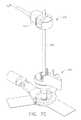
本発明の第1の態様は、本明細書においてポジショナー150として呼ばれている、外科装置の案内部材に関連している。次に、図面において、図1A、図1Bおよび図2は、腹腔鏡の処置のために準備されている患者170と共に使用するためのシステムの各部品の実施形態をそれぞれ示している。なお、腹腔鏡処置の設備は先行技術において周知である。超音波プローブ・センサー120を伴う超音波プローブ・ブラケット125が腹腔鏡超音波プローブ110に取り付けられている。なお、この実施形態は超音波画像化システム100を利用しているが、本発明は超音波装置に限定されず、X線、コンピュータ連動断層撮影(CT)、陽電子放出(PET)または磁気共鳴画像法(MRI)を含むが、これらに限定されない、代替的な画像化方法を含む。同様に、この実施形態はRFアブレーション・プローブ180を利用しているが、本発明は、低温アブレーション・プローブ、マイクロ波アブレーション・プローブ、超音波アブレーション・プローブ、超音波トランスデューサ、加熱化素子等のような、付加的な外科装置の使用を含む。上記の超音波システム100は、制御装置140に伝達される画像データを生成する。また、超音波プローブ・センサー120は、シミュレーションされた三次元空間を形成するために二次元の超音波画像の「スタッキング(stacking)」を補助するために、制御装置140に対して位置および配向の情報を供給する。Surgical Device Guide Member A first aspect of the present invention relates to asurgical device guide member , referred to herein as a
制御装置140は、超音波プローブ・センサー120により供給されるシミュレーションされた三次元の画像および位置の情報を形成するために、超音波プローブ110により生成される超音波の二次元の画像を処理するためのナビゲーション回路およびソフトウエアを含んでいる。この制御装置140は、本発明において用いられているように、単一の装置により構成することができ、一緒に動作する多数の装置として構成することも可能である。なお、当業者は、上記制御装置140の機能が幾つかの部品に分けることができることを、認識するであろう。さらに、表示スクリーン160、キーボード161およびマウス162が制御装置140に接続できる。また、代替的な実施形態は、トラック・ボール、タッチ・スクリーン、スタイラス等のような、別の入力装置も使用可能である。上記の制御装置140は、キーボード161およびマウス162の入力装置ならびに表示スクリーン160を支持している可動のカート210に取り付けられている。また、上記システムにより生成される画像は表示スクリーン160の上に表示される。 The
ポジショナー150は外科装置案内部材であり、同様に制御装置140に接続されているポジショナー・センサー155、を含む。上記の処置の間に、患者170は手術台200の上に横になり、ポジショナー150がその患者170に接触して配置される。その後、アブレーション・プローブ180がポジショナー150の中を通して患者170の体内に挿入される。このポジショナー150は、手術室のテーブル・レール195に取り付けられている固定装置190により、付加的な安定性を与えられている。図2において示されている固定装置190は、マサチューセッツ州、レイハームのコッドマン社(Codman)から市場において入手可能なブックウォルター・エンドスコピック・インストルメント・キット(Bookwalter Endoscopic Instrument Kit)において、利用可能である。また、代替的な実施形態は、患者170に対するポジショナー150の位置を安定化するために、別の固定装置または接着剤を含むことができる。 The
一例の実施形態において、固定装置190は、送信機192を支持する剛性のアーム191を有している。また、代替的な実施形態において、送信機192は、手術室の壁または天井、または任意の他の固定位置に、取り付けることができる。この送信機192からの信号は、超音波プローブ・センサー120およびポジショナー・センサー155の両方により、検知されて、上記システムのための基準点として役立つ。さらに、この固定装置は、ポジショナー150を較正するために用いられる固定されている較正点193も含むことができる。 In one example embodiment, the
一例の実施形態において、ポジショナー150および超音波プローブ110の配向および位置は、ブラッド(Blood)に発行されている米国特許第4,945,305号において記載されているセンサー等のような、磁場センサーに基づいて決定されており、この米国特許第4,945,305号の開示は参照により本明細書に組み入れられている。上記システムは、固定装置190に取り付けられている磁気送信機192と、ポジショナー150に取り付けられている磁気位置センサー155と、超音波プローブ110に取り付けられている磁気超音波プローブ・センサー120と、を含んでいる。また、制御装置140は超音波プローブ110により生成される画像に対してポジショナー150の位置を決定するために必要な計算を実行できる。なお、上記のポジショナー150および超音波プローブ110の位置および配向を決定する幾つかの可能な方法がある。また、代替的な実施形態は、ポジショナー150および超音波プローブ110の位置および配向を検出するために、これらのポジショナー150および超音波プローブ110に取り付けられている光センサーを利用している。また、腹腔鏡カメラ115が、制御装置140により生成される別の表示を伴うこのカメラ115と並べての観察を可能にするために、存在していて、制御装置140に接続されていてもよい。あるいは、この腹腔鏡カメラは独立の手術室モニター116に接続されていてもよい。 In one example embodiment, the orientation and position of the
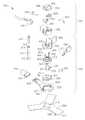
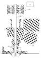
次に、図3Aおよび図3Bを参照して、本発明の第1の態様の第2の実施形態において、ポジショナー150は、ステム組立体300および深さ停止組立体320により、構成されている。このステム組立体の中には、半球形の部分331を含む外側ステム310が存在している。なお、半球形の、とは、本明細書においては、球形の一部分の形状を有することを意味している。上記半球形の部分331はスロット311を伴うステム区域330を有しており、これらのスロット311は、ステム区域330がフレーム340の対応しているフレーム区域341の中におさまることを可能にしている。これらのステム区域330およびフレーム区域341はボール・ジョイントと同様に機能して、外側ステム310がフレーム340に対して回転することを可能にする。また、代替的な実施形態において、外側フレーム310はボール・ジョイントによりフレーム340に接続できる。 3A and 3B, in the second embodiment of the first aspect of the present invention, the
上記外側ステム331の半球形の部分の内表面部に嵌合するステム・フレア要素322を含む、内側ステム315が、外側ステム310の中に位置決めされている。この内側ステム315は通路800を有しており、この通路800の中に、RFアブレーション・プローブ、生検針等のような、針様の外科装置を挿入することができる。なお、この外科装置は入口点371を通してポジショナー150の中に挿入されて、通路800の中を通過して、出口点372においてポジショナー150から出ることができる。上記通路800は形状を円筒形にすることができる。あるいは、この通路800は、当該通路800の側面が外科装置をしっかりと把持するように、多面型または三角形にすることも可能である。上記内側ステム315の基端部は、ステム・ヘッド319をノブ380の中の凹部470の中にスナップ嵌めすることを可能にするノッチ部分318を含む。また、ノブ380は、外側ステムの傾斜面部323に係合する傾斜面部326を有している。このノブ380を把持してこれを一方の側に回転することにより、内側ステム315が外側ステムの中を通して引き動かされ、その結果として、外側ステムの半球形の部分331がその相手側のフレーム区域341の中に引きこまれる。この場合に、各スロット311はステム区域330が拡張することを可能にし、その反作用の力が選択された配向において外側ステム310の角度的な位置を固定して、任意の挿入されている外科装置の経路を係止する。なお、経路、とは、本明細書においては、患者の体内への外科装置の通路を意味する。 An
一例の実施形態において、フレーム340はヒンジ型のジョイントによりホルダー325に取り付けられている。すなわち、このフレーム340は、ホルダー325のヒンジ凹部343に嵌合するヒンジ・ピン342の要素を含む。さらに、スナップ・レバー391がホルダー325の中にフレーム340を固定するためにスナップ・キャッチ392に係合している。また、これらのスナップ・レバー391およびスナップ・キャッチ392を離脱させることにより、フレーム340がホルダー325から回転して出ることが可能になり、外科医が患者170の皮膚に接近することが可能になる。ホルダー325は、患者170の皮膚に載っている下面部327を有している。ステム区域330の中心は下面部327の上か、この下面部327のわずかに下方に、配置されており、そのステム区域330の中心が患者170に接触して置かれている。このような実施形態において、ステム区域330の角度的な回転の中心は、そのステム区域330の半球形の形状により、相当な皮膚の変形を伴わずに患者170の皮膚に、または、その近くに存在する。このように、上記の回転の中心を皮膚の表面に、または、その近くに配置することにより、皮膚の中の切開部分を通しての角度的な移動の範囲を最大にして、必要とされる切開部分の大きさを最小限にすることができる。一例の実施形態において、ホルダー325は、固定装置190における相手側のレセプタクル304に取り付けることができるクリップ・エンド303を有している。また、ホルダー325は当該ホルダー325の位置を患者170に対して固定するために柔軟な安定化部材350も利用できる。この柔軟な安定化部材350は、ホルダー325の平坦な領域327にその安定化部材350を取り付けることを可能にするリング状の接着剤316と、患者170に付着する患者用の接着剤317と、を有している。さらに、この患者用の接着剤317は、患者170におけるポジショナー150の最終的な配置の前に柔軟な安定化部材350が付着することを防ぐために、剥離可能なカバー355により被覆されている。 In one example embodiment,
上記の深さ停止組立体320はノブ380の上部に固定されていて、偏向フィンガー360により外側ステム310に取り付けられている。この深さ停止組立体320は、センサー・フレーム385と、エンド・ディスク370と、2個のボタン・キャッチ390と、これらのボタン・キャッチ390のそれぞれの弾性のバンド395と、により構成されている。上記偏向フィンガーの棚365はエンド・ディスク370のリップ部分366にそれぞれ係合している。また、深さ停止組立体320は、ポジショナー150の位置および配向の情報を制御装置140に伝達するために、センサー・フレーム385の中にはめこまれている位置センサー155を利用している。さらに、センサー・フレーム385はボタン・キャッチ390およびこれらのそれぞれの弾性のバンド395を収容している。この場合に、ボタン・キャッチ390を押しこむことにより、偏向フィンガー360が曲がり、深さ停止組立体320が外側ステム310から放出される。また、エンド・ディスク370は深さ停止組立体320を被覆して、その位置が固定されている。 The
一例の実施形態において、可動のシャッター345が外側ステム310に取り付けられていて、外科装置がポジショナー150の通路800の中を通過することを阻止する。このシャッター345はシャッター停止部材307を組み入れており、このシャッター停止部材307はウインドウ・アクセス・ポート306の中を通過して、通路800の中に突出する。また、シャッター345は弾性のリング305によりその位置が保持されており、この弾性のリング305はシャッター345が旋回することを可能にしている。この結果、ポジショナー150の中に挿入されている外科装置は、既知の固定されている基準位置において、シャッター停止部材307の上に静止する。さらに、このシャッター停止部材307を通路800から除去して外科装置がポジショナー150を通過することを可能にするために、シャッター345は引っ張られるが、ウインドウ・アクセス・ポート306からは除去されない。代替的な実施形態において、上記シャッター345はばねにより付勢されているヒンジ型のジョイントにより外側ステム310に取り付けることができる。この場合に、シャッター345に圧力が加えられると、この圧力はそのシャッター345を旋回させて、シャッター停止部材307を通路800から除去する。さらに、異なる直径の外科装置を適応させるために通路800の中にインサート335を配置することも可能である。 In one example embodiment, a
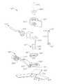
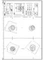
次に、図4Aおよび図4Bにおいて、本発明の第1の態様の第2の実施形態である、ポジショナー150′は、外側ステム310′の中に収容されていて、注封エポキシ314′により位置が保持されており、制御装置140′に接続されている、ポジショナー・センサー155′を含んでいる。この代替的な実施形態は、前述の実施形態において説明されているような深さ停止組立体320またはシャッター345、を含まない。しかしながら、前述の実施形態と同様に、内側ステム315′の基端部は、ステム・ヘッド319′をノブ380′の凹部470′の中にスナップ嵌めすることを可能にするノッチ部分318′を有している。このような実施形態において、キャップ460′が、ステム・ヘッド319′の位置をしっかりと維持するために、そのステム・ヘッド319′の中に挿入されている。さらに、異なる直径の外科装置を適応させるために通路800′の中にインサート335′を配置することも可能である。 Next, in FIGS. 4A and 4B, a
本発明の第1の態様の第1の実施形態において、上記ノブ380′は、外側ステムの傾斜面部323′に係合する傾斜面部326′を有している。このノブ380′を把持してこれを一方の側に回転することにより、内側ステム315′が外側ステムの中を通して引き動かされ、その結果として、外側ステムの半球形の部分331′がフレーム340′における相手側のフレーム区域341′の中に引きこまれる。この場合に、各スロット311′は外側ステム310′のステム・フレア要素322′のステム区域330′が拡張することを可能にし、その反作用の力が選択された配向において外側ステム310′の角度的な位置を固定して、任意の挿入されている外科装置の経路を係止する。 In the first embodiment of the first aspect of the present invention, the knob 380 'has an inclined surface portion 326' that engages the inclined surface portion 323 'of the outer stem. By grasping and rotating this knob 380 'to one side, the inner stem 315' is pulled through the outer stem, so that the hemispherical portion 331 'of the outer stem is moved into the frame 340'. Into the opposite frame area 341 '. In this case, each slot 311 'allows the stem section 330' of the stem flare element 322 'of the outer stem 310' to expand so that its reaction force is angular in the outer stem 310 'in a selected orientation. Locks in place and locks the path of any inserted surgical device.
一例の実施形態において、上記フレーム340′は、ホルダー325′のヒンジ凹部343′に嵌合するヒンジ・ピン342′の要素により、そのホルダー325′に取り付けられている。さらに、スナップ・レバー391′がホルダー325′の中にフレーム340′を固定するためにスナップ・キャッチ392′に係合している。また、ホルダー325は′、ポジショナー150′の位置を保持するために、固定装置190′における相手側のレセプタクル304′に取り付けることができるクリップ・エンド303′を有している。また、ホルダー325′は当該ホルダー325′の位置を患者170′に対して固定するために柔軟な安定化部材350′も利用できる。この柔軟な安定化部材350′は、ホルダー325′における平坦な領域327′にその安定化部材350′を取り付けることを可能にするリング状の接着剤316′と、患者170′に付着する患者用の接着剤317′と、を有している。さらに、この患者用の接着剤317′は、患者170′におけるポジショナー150′の最終的な配置の前に柔軟な安定化部材350′が付着することを防ぐために、剥離可能なカバー355′により被覆されている。 In one example embodiment, the frame 340 'is attached to the holder 325' by an element of a hinge pin 342 'that fits into a hinge recess 343' of the holder 325 '. In addition, a snap lever 391 'engages the snap catch 392' to secure the frame 340 'in the holder 325'. The
次に、図5を参照して、一例の実施形態において、上記ポジショナーのステム組立体300は、スナップ・キャッチ392からスナップ・レバー391を離脱させることにより、患者の皮膚をさらすために回転できる。ホルダー325の中の4個のスロット410は、皮膚の切り傷の案内要素として作用し、メスが、皮膚の中を通る外科装置の容易な挿入のために、これらのスロットの間に経皮的な切開部分を作ることを、可能にしている。その後、スナップ・レバー391およびスナップ・キャッチ392を再び係合することにより、外側ステム310が、ポジショナー150の中において、その固定された位置に戻る。代替的な実施形態において、ステム組立体300は、当該ステム組立体300が皮膚をさらすためにホルダー325から除去可能になるように、ヒンジ型のジョイントよりはむしろ、多数のスナップ・キャッチを用いているホルダー325に接続することが可能である。さらに別の代替的な実施形態において、ホルダー325からステム組立体300を除去することなく、皮膚に切り傷を付けるために、ランスを通路800の中を通して挿入することも可能である。 Referring now to FIG. 5, in one example embodiment, the
次に、図6Aおよび図6Bを参照して、一例の実施形態において、上記の深さ停止組立体320は、当該深さ停止組立体320が外側ステム310から除去されることを可能にするボタン・キャッチ390を含む。ポジショナー150が係止されていない位置にある時に、ノブ380はボタン・キャッチ390の内の1つを覆って、深さ停止組立体320が外側ステム310から除去されることを防ぐ。一方、ノブ380を係止されている位置に回転すると、第2のボタン・キャッチ390が露出する。これらのボタン・キャッチ390を押しこむと、貫通穴397が整合して、深さ停止組立体320が外側ステム310から除去可能になる。 6A and 6B, in one example embodiment, the
次に、図6C、図6Dおよび図6Eを参照して、一例の実施形態において、ボタン・キャッチはセンサー・フレーム385のポスト430に取り付けられている弾性のバンド395により付勢されている。この場合に、ボタン・キャッチ390を押しこむと、これらの弾性のバンド395が伸びて、貫通穴397が整合する。さらに、ポジショナー・センサー155を伴わないクランプを用いている深さ停止組立体320の構成の代替的な実施形態が図6Dおよび図6Eにおいて示されている。 6C, 6D, and 6E, in one example embodiment, the button catch is biased by a
次に、図7A、図7B、図7Cおよび図7Dにおいて、ボタン・キャッチ390が押し込まれると、貫通穴397が整合する。これにより、アブレーション・プローブ180は、当該アブレーション・プローブ180が、既知の、固定されている、基準位置において、シャッター停止部材307に対して静止するまで、貫通穴397の中を通して通路800の中に挿入できる。この場合に、ボタン・キャッチ390を押しこむと、偏向フィンガーが移動して、深さ停止組立体320が外側ステム310から除去されてアブレーション・プローブ180の上に位置決めされることが可能になる。一方、ボタン・キャッチ390が放出されると、貫通穴397が不整合になり、アブレーション・プローブ180を把持する。それゆえ、これらの貫通穴397は、アブレーション・プローブ180の上に深さ停止組立体320の位置を固定するクランプとして、作用する。 Next, in FIGS. 7A, 7B, 7C, and 7D, when the
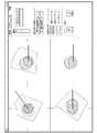
次に、図8Aおよび図8Bにおいて、本発明の第1の態様の第3の実施形態は、外科医がホルダー325を患者に付着した後に挿入点を調節することを可能にする摺動ディスク310″を含む。本明細書においては、挿入点は、アブレーション・プローブが挿入される患者の皮膚における点、である。図8Aおよび図8Bにおいて示されている実施形態において、ステム組立体200″は、先端部において半球形の部分231″を伴う単一のステム210″を有している。この半球形の部分231″は、フレーム240″の対応しているフレーム区域241″の中におさまるステム区域230″と、患者250″に載っている下面部と、を有している。これらのステム区域230″およびフレーム区域241″はボール・ジョイントと同様に機能し、ステム210″がフレーム240″に対して回転することを可能にしている。それゆえ、ステム区域230″の角度的な回転の中心は、皮膚の相当な変形を伴わずに、患者250″の皮膚にあるか、その近くにあり、その患者250″の皮膚の中の小さな切開部分の中を通る移動の範囲を最大にしている。係止ノブ220″はねじ付きの表面によりステム210″に取り付けられている。この係止ノブ220″は、ディスク要素245″に載っている係止ノブ区域233″を有している。さらに、ディスク要素245″はフレーム240″に載っている。 Next, in FIGS. 8A and 8B, a third embodiment of the first aspect of the present invention is a sliding
ステム210″の軸260″はポジショナー150″の経路を決定する。すなわち、ノブ215″を把持してこれを一方の側に移動することにより、ステム210″がステム区域230″の中心の回りに旋回し、ポジショナー150″および任意の挿入されている外科装置の経路が変わる。半球形の部分231″の下面部は患者250″の皮膚の上において静かに動き、ステム区域230″の中心が患者に対して接触している状態を維持することを可能にする。さらに、このステム区域230″は、これに接していて、対応しているフレーム240″の区域に対して摺動する。加えて、係止ノブ区域233″が、ディスク要素245″において近接している区域に対して摺動して、そのディスク要素245″をフレーム240″の中のスロットの中に移動する。 The
係止ノブ220″は、経路が計画された後に、ステム210″を固定された位置に係止するために使用できる。この場合に、係止ノブ220″が一方向に回転することにより、係止ノブ区域233″がディスク要素245″の中における相手側の区域に対して押圧されて、ステム区域230″がフレーム240″に接している点において、半球形の部分231″がフレーム240″に対して引きこまれる。この結果、その反作用の力がステム210″を選択された位置に係止する。 The locking
上記の摺動ディスク310″は、基部320″の位置が固定された後に外科装置の挿入点が調節されることを可能にする。この場合に、フレーム240″はヒンジ・ジョイントによりプラットホーム300″に取り付けられている。また、プラットホーム300″は、ホルダー320″の上に存在している摺動ディスク310″を有している。それゆえ、上記の挿入点はホルダー320″の上の摺動ディスク310″を移動することにより変えることができる。また、リング330″は、ホルダー320″のねじ付きの表面225″に対してインターフェイスとなるねじ付きの表面335″を含む。この場合に、リング330″を一方向に回転することにより、そのリング330″のエッジ部分が摺動ディスク310″に対して押圧される。この結果、リング330″およびホルダー320″による摩擦力が摺動ディスク310″の位置を固定する。 The sliding
上記の代替的な実施形態において、ポジショナー・センサー175″はステム210″のノブ部分215″の中にはめ込まれている。このポジショナー・センサー175″の電線はステム・スロット207a″の中に入り、内側スロット206″を横切り、ステム・スロット207b″から出ている。このポジショナー・センサー175″の電線は、その後、フレーム240″を通過して、エッジ・カード208″において終わっている。さらに、ポジショナー送信機178″が、フレーム240″に取り付けられるクランプ・アーム260″の中に、はめ込まれている。このポジショナー送信機178″の電線はケーブル265″の中に包まれている。また、上記クランプ・アーム260″は、フレーム240″の中のエッジ・カード208″に対して嵌合する伸縮自在の部材290″の内の1つの中のはめ込み型のエッジ・カード280″を含んでいる。さらに、フレーム240″の中のエッジ・カード208″からの電線は、クランプ・アーム260″の中にはめ込まれているエッジ・カード280″の電線に接続している。上記伸縮自在の部材290″の先端部分295″はフレーム240″の溝部297″の中にスナップ嵌めされている。さらに、クランプ・アーム260″のタブ296″は、当該クランプ・アーム260″の位置を保持するために、プラットホーム300″の中の凹部298″をつかんでいる。 In the alternative embodiment described above, the
ポジショナー150″は、外科医がステム組立体200″の中心に整合されている経皮的な切開部分を作成することを補助する皮膚の切り傷の案内要素330″を含んでいる。また、プラットホーム300″は、ステム組立体200″がプラットホーム300″の中心から回転して出ることを可能にするステム・ヒンジ部315″を含んでいる。さらに、プラットホーム300″は、皮膚の切り傷の案内要素330″の中のスロットがプラットホーム300″の中の孔の中心に対して整合されるように、皮膚の切り傷の案内要素330″がプラットホーム300″の中心に回転することを可能にする、皮膚の切り傷の案内要素用のヒンジ部321″も含んでいる。これにより、使用状態でない場合に、皮膚の切り傷の案内要素330″はプラットホーム300″から回転して出ている。上記ホルダー320″は患者120″にポジショナー150″を取り付けるための接着剤340″を含んでいる。この接着剤340″は、当該接着剤340″がポジショナー150″の最終的な配置の前に付着することを防ぐために、剥離可能なカバー350″を有している。さらに、異なる直径の外科装置を適応させるためにステム210″の中にインサート190″を配置することも可能である。 The
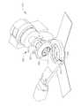
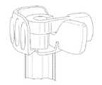
次に、図9Aおよび図9Bを参照して、本発明の第1の態様の第4の実施形態において、ポジショナー900は外科装置の経路の変更を容易にするためにドーム型の構造を利用している。このポジショナー900は、先端部にステム・フレア要素904を伴うステム902、を含んでいる。このステム・フレア要素904はフレーム908の対応しているフレーム区域905の中におさまっていて、ボール・ジョイントと同様に機能する。上記ステム902は外科装置の挿入のための通路926を有している。また、このステム部902は、ポジショナー・センサー(図示せず)を収容しているセンサー・アーム906を含んでいる。この場合に、フレーム908はホルダー910の中に収容されていて下方ドーム912に取り付けられている。この下方ドーム912は、当該下方ドーム912をホルダー910に取り付けるためにそのホルダー910のリップ部分916に係合するフィンガー914を有している。さらに、スナップ・キャッチ918がホルダー910に旋回可能に取り付けられている。このスナップ・キャッチ918を押し下げることにより、下方ドーム912のフィンガー914の内の1つが放出されて、下方ドーム912がホルダー910から除去されることが可能になる。このホルダー910からの下方ドーム912の除去はまた、フレーム908をホルダー910から除去して、ホルダー910の位置が固定された後でさえも、外科医が患者の皮膚に接近することも可能にする。このホルダー910は柔軟な安定化部材(図示せず)を用いて患者に固定することもでき、あるいは、代替的な実施形態において、このホルダー910は、固定装置に取り付けることのできるクリップ・エンドを含むことも可能である。さらに、上方ドーム920が下方ドーム912の上に静止している。この場合に、センサー・アーム906の中に収容されているポジショナー・センサー(図示せず)からの電線は、そのポジショナー・センサーを制御装置に接続するために、上方ドーム920の中のスロット928を通過できる。また、ステム902が上方ドーム920の中のカラー922を通過している。さらに、ねじ付きの表面を含むノブ924がステム902におけるねじ付きの表面に係合している。このノブ924は、外科装置を挿入することができる通路926、を含んでいる。 9A and 9B, in a fourth embodiment of the first aspect of the present invention, the
上記の上方ドーム920および下方ドーム912の構成は、外科医がポジショナー900の経路を操作することを、可能にする。すなわち、上方ドーム920が下方ドーム912の表面の上を摺動して、ステム902が回転することを可能にする。さらに、外科医は、ノブ924を把持して移動させることにより、挿入の角度を変えることができ、これにより、ステム902および外科装置が挿入される通路926の角度を変えることができる。なお、この挿入の角度は、ステム902を囲っているカラー922と下方ドーム912の上部のエッジ部分との間の接触により、制限されている。この場合に、下方ドーム912の中のスロット930およびフレーム区域905の中のマッチング・フレーム・スロット934が、上記挿入の角度、それゆえ、上記の経路、の範囲を増加する。すなわち、カラー922は、上記挿入の角度を増加するために、スロット930の中に挿入できる。さらに、このカラー922が下方ドーム912の中のスロット930の中に挿入されると、ステム902がフレーム区域905の中のマッチング・フレーム・スロット934の中に挿入される。この場合に、上方ドーム920における矢印932は、カラー922が、センサー・アーム906による妨害を伴わずに、下方ドーム912の中のスロット930の中に挿入できるように、上方ドーム920が整合される時を示す。また、下方ドーム912はホルダー910の中において360度で回転可能であり、これにより、外科医が、必要に応じて、スロット930およびフレーム・スロット934の位置を変えること、を可能にしている。 The configuration of the
好ましい経路が設定されると、外科医はポジショナー900の経路を係止できる。すなわち、この経路はノブ924を把持して回転することにより係止できる。この場合に、ノブ924を一方向に回転すると、ステム902がカラー922の中を通して上方に引き動かされ、そのステム902のステム・フレア要素904が相手側のフレーム区域905の中に引き込まれる。同時に、ノブ924の下部がカラー922を下方に押圧する。この結果、反作用の力がステム902の角度的な位置を選択された配向に固定して、通路926の中に挿入されている外科装置の経路を係止する。 Once the preferred path is established, the surgeon can lock the path of the
本発明の第1の態様の第5の実施形態において、深さ停止組立体320はポジショナー150の残りの部分から独立して使用できる。この深さ停止組立体320は、患者170の体内における外科装置の挿入を制御するために、固定されている形状の任意の外科装置と共に使用できる。最初に、ポジショナー・センサー155を含んでいる、上記の深さ停止組立体は、一つの挿入点に関連づけられる。次に、その深さ停止組立体は、既知の固定されている形状を有している外科装置の上に、配置される。この外科装置の先端部分は深さ停止組立体に対して既知の基準点において配置される必要がある。これらの、外科装置の既知の形状およびその基準点および深さ停止組立体の位置および配向を用いて、制御装置140は患者170の体内への挿入時における外科装置の先端部分の位置を計算できる。図面において、上記の深さ停止組立体が針様の外科装置に関連して例示されている。しかしながら、この深さ停止組立体は、形状が知られていて制御装置140に入力されていれば、固定されている形状の任意の外科装置と共に使用可能である。 In a fifth embodiment of the first aspect of the present invention, the
組織の上に治療の標的をマッピングする方法
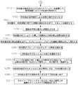
次に、図10Aおよび図10Bにおいて、本発明の第2の態様は患者の体内の腫瘍または病巣を治療するための方法に関連している。この方法の一例の実施形態は、工程500において、設備を組み立てることから開始している。例えば、腹腔鏡処置のための方法の構成はそれぞれ独立している外科用の参考文献において十分に確立および立証されている。任意の製造者のアブレーション・プローブがこの実施形態において使用可能である。従って、アブレーション・プローブ180は製造者の製品情報の中に存在しているものとして利用されている。なお、この方法はアブレーション・プローブの使用に限定されておらず、任意の外科装置の案内において適用できる。図1Bおよび図2において示されているような、一例の実施形態において、キーボード161と、マウス162と、表示スクリーン160と、を含んでいる可動カート210が存在していて、制御装置140に接続されている。また、超音波プローブ・センサー120を伴う超音波プローブ・ブラケット125が超音波プローブ110の上に取り付けられている。加えて、超音波システム100およびポジショナー・センサー155も制御装置140に接続されている。さらに、腹腔鏡カメラ115が、独立して、手術室モニター116に接続されている。Method of Mapping Treatment Target on Tissue Next, in FIGS. 10A and 10B, a second aspect of the present invention relates to a method for treating a tumor or lesion in a patient's body. An example embodiment of the method begins with assembling equipment at
工程510において、固定装置190が、この固定装置の自由な先端部が軽い摩擦状態で挿入点の近くに配置されるように、手術室のテーブル・ベッド・レール195に取り付けられる。この固定装置190は、送信機192を支持している第2の剛性のアーム191を有している。この送信機192は上記の方法の間に基準点として役立ち、制御装置140に接続されている。一方、ポジショナー150は固定装置190の自由端部に取り付けられている。次に、上記方法の工程520において、外科医は腹腔鏡カメラ115および超音波プローブ110を組織部位までそれぞれのトロカールの中を通過させる。 In
次に、工程530において、外科医は超音波プローブ110およびポジショナー150を較正する。一例の実施形態において、超音波プローブ110における超音波プローブ・センサー120の位置が制御装置140により知られている。また、代替的な実施形態において、外科医はキーボード161およびマウス162を用いて超音波プローブ・センサー120の物理的な位置に関する情報を入力できる。さらに、一例の実施形態において、制御装置140により、ポジショナー150におけるポジショナー・センサー155の位置が知られている。また、代替的な実施形態において、外科医はポジショナー・センサー155の物理的な位置に関する情報を入力できる。さらに代替的な実施形態において、ポジショナー・センサー155に対する、入口点371および出口点372の位置、それゆえ、通路800の位置および配向、が制御装置140により計算できる。これらの入口点371および出口点372の位置を計算するためには、外科医は、最初に、その入口点371を、較正点193(図2において示されている)等のような、一つの固定されている位置に、配置する必要がある。その後、外科医はポジショナー150を入口点371の回りに旋回させて、その入口点371を較正点193において保持する必要がある。この旋回動作の間に、ポジショナー・センサー155は入口点371を中心とする球面の一部分を書き表す。従って、このポジショナー・センサー155により書き表される球面の中心を計算することにより、制御装置140はポジショナー・センサー155と入口点371との間の関係を決定することができる。同様に、外科医が出口点372を較正点193に配置して、ポジショナー150をその出口点372の回りに旋回させれば、制御装置140はポジショナー・センサー155に対する出口点372の位置を決定することができる。さらに、これらの入口点371および出口点372の位置に基づいて、制御装置140はポジショナー150の通路800の中に挿入されている外科装置の経路を計算することができる。 Next, in step 530, the surgeon calibrates the
外科医は、また、工程530において、超音波画像化システムを較正することもできる。すなわち、制御装置140が現存の超音波画像化システムにより生成される出力データを利用できる。例えば、この制御装置140は表示スクリーン160に上記の超音波画像化システムにより伝達される出力データを使用できる。このデータは、体内の空間の一部分の超音波の二次元の表現だけでなく、患者の名前等のような、付加的な情報も含むことができる。このような超音波システムを較正するために、外科医または専門技術者は、その体内の空間の二次元の表現を含む表示スクリーン160の部分を確認できる。この表示スクリーンの部分が確認されると、制御装置140は、その体内の空間の二次元の表現と、基準点として役立つ送信機192に対するその体内の空間の二次元の表現の位置を決定するための超音波プローブ・センサー120の位置と、の間の関係を決定することができる。 The surgeon can also calibrate the ultrasound imaging system at step 530. In other words, the
次に、図10A、図10Bおよび図11を参照して、工程540において、制御装置140は超音波取得モードにおいて開始して、超音波プローブ110が所望の組織の画像を捕捉するために用いられる。この場合に、外科医は体内の空間の一部分の二次元の表現を生成するために超音波プローブ110を使用できる。すなわち、超音波プローブ110を移動することにより、外科医は体内の空間の一連の二次元の表現から成るデータの組を生成させることができる。この場合に、超音波プローブ・センサー120から受け取られる位置情報を使用しながら、超音波プローブ110は上記の二次元の表現を生成し、制御装置140がこれら二次元の表現を、スタッキングして「stacks」、その体内の空間の一部分の三次元の画像またはモデルを作る。従って、この取得モードにおいて、外科医は表示スクリーン160の上においてその三次元の画像を見て、腫瘍組織がその三次元の画像において完全に見えることを確実にすることができる。制御装置140は、図11において示されているように、3種類の正射投影図および画像の斜位シミュレーション三次元の図を表示スクリーン160の上に作ることができる。一例の実施形態において、外科医は画像の幾つかのデータの組を生成させて、治療計画を生成させるための最良のデータの組を選択することができる。 Next, with reference to FIGS. 10A, 10B, and 11, at
次に、図10A、図10Bおよび図12を参照して、工程550において、外科医は制御装置140を用いて腫瘍の輪郭を確認するために三次元の画像の全体をスクロールして各図を操作する。一例の実施形態において、外科医は、マウス、スタイラスまたはライト・ペンを用いるフリーハンドの線画を含む、種々の方法を用いて、腫瘍の輪郭を確認することができる。加えて、外科医はそれぞれの正射投影図のいずれかにおいて関連の円を選択できる。このようにして、正射投影図のそれぞれにおいて円形の領域を選択することにより、外科医は、有効に、組織の空間の輪郭を描くことが可能になる。なお、これらの円を描くためのソフトウエアによる方法が先行技術において十分に確立されている。この実施形態において、外科医は一つの正射投影図の上の2個の点を選択するようにマウスを用いることにより、一つの円を定めることができる。この場合に、第1の点はその円の中心を定める。また、この第1の点から所与の距離に配置されている、第2の点は半径を設定する。一例の実施形態において、工程550において選択された3個の円のそれぞれは、その三次元画像の中において一つの円筒または円柱のデータを定める。さらに、制御装置140はこれら3個の円柱の交点を解析して、その腫瘍の空間を定める。また、外科医は、腫瘍の空間の輪郭を定めるために、カッティング・プレーン等のような、付加的な線画ツールを利用することも可能である。1本の線を形成するように正射投影図のいずれか1つにおいて2つの点を選択することにより、外科医は一つのカッティング・プレーンを定めることができる。さらに、そのカッティング・プレーンの一方の側に第3の点を選択することにより、外科医はそのカッティング・プレーンのその一方の側におけるデータの全てを削除または除去できる。また、代替的な実施形態は、付加的な幾何学形状およびこれらの形状を定めるための方法、を利用することを含むことができる。なお、当業者は空間を定めるための多数の方法が存在することを認識するであろう。 Next, with reference to FIGS. 10A, 10B, and 12, in
腫瘍の輪郭が設定されると、制御装置140は、工程560において、その輪郭を用いてその腫瘍の空間を処理する。この場合に、制御装置140は、図12において示されているシミュレーションされた三次元の図において例示されているように、表示スクリーン160から、腫瘍の輪郭の外側の全てのデータを除去できる。また、制御装置140は外科医により確認されている腫瘍の輪郭の中のデータも解析できる。一般に、腫瘍組織の密度は正常な組織の密度とは異なる。そこで、画素の密度により表現されるような、相対的な組織の密度を比較することにより、制御装置140は腫瘍組織を確認して、その腫瘍の輪郭をさらに正確にすることができる。 Once the tumor outline is set, the
代替的な実施形態において、外科医は、腫瘍の一部であるとして、表示スクリーン160の上に一つの点を確認することができる。この場合に、制御装置140はその外科医により選択された点の組織の密度をその周囲の組織の密度に対して比較できる。この結果、その組織の密度が変化している画像の中の領域を決定することにより、制御装置140はその腫瘍の空間を確認できる。その後、制御装置140は表示スクリーン160の上に示されている図のそれぞれの中の腫瘍の空間の境界線を強調できる。次に、工程570において、腫瘍の空間が、操作および測定することのできる三次元に加工された図として、表示スクリーン160の上に示される。 In an alternative embodiment, the surgeon can see a point on the
次に、外科医は、工程580において、アブレーションのプランニングのために、腫瘍の空間を拡張するように、マージン・オフセットを適用できる。さらに、この拡張された空間に基づいて、外科医は適当なアブレーション・プローブ180を選択して、長さ、アブレーションの直径、および物理的なプローブの先端部分からのアブレーションの直径のオフセット等のような、選択されたプローブのアブレーション・パラメータを入力できる。なお、これらのパラメータはキーボード161およびマウス162を用いて制御装置140に入力できる。 The surgeon can then apply a margin offset in
次に、図10A、図10Bおよび図13を参照して、上記方法の工程590において、外科医が上記の取得モードにおいて取得された画像に満足すると、制御装置140はプランニング・モードに更新される。なお、本明細書においては、治療空間は、アブレーション・プローブ180が静止して保持されて電圧を加えられる時に、そのアブレーション・プローブ180により影響を受ける組織の空間、である。また、標的の治療空間は、アブレーション・プローブによりアブレーションされるか治療される組織の空間、である。このプランニング・モードにおいて、外科医は、所望の適用範囲または「マッピング計画表(mapping scheme)」が達成されるまで、アブレーション・プローブ180のアブレーション・パラメータに基づいて、標的の治療空間を腫瘍の空間の上に置くことができる。その後、外科医は、表示スクリーン160の上にカーソルを向けるために、マウス162等のような、入力装置を用いて、標的の治療空間の位置を選択できる。これにより、表示スクリーン160の上の番号付けされたリファレンス・テーブルが、標的の治療空間を、これらが治療される順序で、列挙する。さらに、このリファレンス・テーブルを操作することにより、外科医は治療の順序を変更するか、標的の治療空間を削除できる。この場合に、制御装置140の中のソフトウエアが腫瘍の空間の適用範囲の評価を可能にする。一例の実施形態において、制御装置140は標的の治療空間のいずれにも含まれていない腫瘍の空間の任意の部分を指示する。また、代替的な実施形態において、制御装置140は標的の治療空間を自動的に計算して一つのマッピング計画表を生成できる。次に、工程600において、制御装置140は直交の三次元の図の上に個々の標的の治療空間の位置を動的に表示する。なお、これらの治療空間は、外科医が、選択された治療空間と、既に治療されている標的の治療空間と、まだ治療されていない標的の治療空間と、を識別することを可能にするために、カラー・コード化されていてもよい。 10A, 10B and 13, at step 590 of the method, when the surgeon is satisfied with the image acquired in the acquisition mode, the
次に、図10A、図10Bおよび図14を参照して、工程610において、上記のマッピング計画表が定められた後に、制御装置140は治療モードに更新される。この治療モードにおいては、治療される予定の次の標的の治療空間である、選択された治療空間が強調されて、ポジショナーの経路が表示スクリーン160の上に示される。この経路はポジショナー150から出ている仮想の直線状の光線であり、患者の体内のアブレーション・プローブ180の投影された経路を示している。なお、この経路の線は、ポジショナー150が移動する際に、表示スクリーン上において更新される。この場合に、制御装置140は、基準点として役立つ送信機192に対するポジショナー・センサー155の位置および配向に基づいて、ポジショナー150の経路を計算できる。なお、ポジショナー・センサー155は、アブレーション・プローブ180が挿入される通路800に対して固定されている関係にある。また、上述したように、体内の空間の三次元画像が、基準点として、送信機192を用いて、制御装置140により生成されている。従って、この共通の基準点は、制御装置140が表示スクリーン160の上の直交のシミュレーションされた三次元の図の上にポジショナー150の経路を投影すること、を可能にしている。 Next, referring to FIG. 10A, FIG. 10B and FIG. 14, in
上記の投影された経路を用いて、外科医はアブレーション・プローブ180のための挿入点を選択できる。ポジショナー150は皮膚の表面の上を移動することができ、外側ステム310の角度は、ポジショナーの経路および挿入点が所望の位置になるまで、調節できる。ポジショナー150が所望の挿入点に位置すると、剥離可能なカバー355が柔軟な安定化部材350から除去されて、ポジショナー150が患者170に対して軽く押し当てられる。その後、上記の柔軟な安定化部材における患者用の接着剤317がポジショナー150を患者170に対して付着させる。また、固定装置190の位置も係止できるようになる。また、代替的な実施形態において、ポジショナー150は、固定装置190単独で、または柔軟な安定化部材350単独でその位置を保持することも可能である。 Using the projected path described above, the surgeon can select an insertion point for the
次に、図8Aおよび図8Bを参照して、さらに代替的な実施形態において、送信機178″はクランプ・アーム260″の中に含まれていてもよい。このような実施形態において、クランプ・アーム260″は、一定の基準点を与えるために、挿入点の選択中に静止して保持される必要がある。その後、ポジショナー150″が挿入点に位置すると、クランプ・アーム260″がそのポジショナー150″のフレーム240″に取り付けることができるようになり、この場所において、そのポジショナー150″は固定された位置を維持するようになる。この点において、新しい三次元の画像がその新しい基準点を用いて生成される必要がある。 Referring now to FIGS. 8A and 8B, in a further alternative embodiment, the
次に、図5および図10を参照して、工程620において、スナップ・レバー391がスナップ・キャッチ392から離脱すると、フレーム340がはずれる。このフレーム340は回転することにより、ホルダー325の中のスロット410をさらす。これらのスロット410は、外科医がアブレーション・プローブ180の容易な挿入を可能にするために経皮的な切開部分を作ることを可能にする。この切開部分が作られた後に、フレーム340は回転して元の位置に戻り、スナップ・レバー391がスナップ・キャッチ392に再び係合してフレーム340を固定する。あるいは、経皮的な切開部分を作るために、ランスを通路800の中を通して挿入してもよい。 Next, referring to FIGS. 5 and 10, in
次に図3A、図3Bおよび図10を参照して、工程630において、ポジショナー150の経路が、外側ステム310を回転して、表示スクリーン160の上に示されている経路インジケータを利用することにより、選択された治療空間に対して整合される。一例の実施形態において、表示スクリーン160は、ポジショナー150の経路が選択された治療空間に対して整合される時を指示する。この経路が整合されると、ポジショナー150は、ノブ380を回転することにより、その位置に係止できるようになる。さらに、ノブ380を回転することにより、図6Aおよび図6Bにおいて示されているような、第2の深さ停止ボタン・キャッチ390がさらされる。この場合に、表示スクリーン160は皮膚の上のポジショナー150の配置から選択された治療空間に対応する標的点までの距離を示す。なお、この標的点は、本明細書においては、アブレーション・プローブの先端が標的の治療空間をアブレーションするために配置されることが必要である点、である。また、代替的な実施形態において、表示スクリーン160は、標的の治療空間のそれぞれに対応する標的点、を指示できる。さらに、表示スクリーン160は、ポジショナーの経路が選択された治療空間の標的点に対して整合される時も指示できる。 Referring now to FIGS. 3A, 3B and 10, in
工程640において、深さ停止ボタン390を押しこむと、貫通穴397が整合して、通路800の中へのアブレーション・プローブ180の挿入が可能になる。このアブレーション・プローブ180は、当該アブレーション・プローブ180の先端部分が、図7Aおよび図7Bにおいて示されているように、シャッター停止部材307に接触するまで、ポジショナー150の中に挿入されている。また、ポジショナー・センサー155は、アブレーション・プローブ180が収容される通路800に対して固定されている関係にあり、これにより、制御装置140は、そのポジショナー・センサー155の位置および配向に基づいて、挿入されているアブレーション・プローブ180の位置および配向を計算できるようになる。 In
上記制御装置140の深さ停止モードを用いて、外科医は、その深さの停止位置が患者の体内へのアブレーション・プローブ180の挿入を、上記の挿入点から標的点までの距離に制限するように、アブレーション・プローブ180に関して深さの停止位置を位置決めすることができる。最初に、外科医はキーボード161またはマウス162を用いて上昇深さ停止モードを選択できる。この上昇深さ停止モードにおいて、表示スクリーン160は深さ停止位置に基づいて読み出し情報を示す。この読み出し情報は、アブレーション・プローブの軸に関する深さ停止の高さが、そのアブレーション・プローブが選択された治療空間を治療するために挿入されることが必要である深さに等しくなるまで、深さ停止組立体320がそのアブレーション・プローブの軸に沿って持ち上げられる時に、ゼロに下がる。なお、この寸法は、工程580における外科医により入力されるのに従って、アブレーション・プローブの物理的な端部からの有効なアブレーションの空間の任意のオフセットに対応する調節を含んでいる。図7Cは、アブレーション・プローブの軸に沿って持ち上げられている深さ停止組立体320を示している。この深さ停止組立体320が適当な高さまで持ち上げられると、深さ停止ボタン390の解放により、貫通穴397が不整合になる。この結果、これらの貫通穴397の壁部は、クランプのように、アブレーション・プローブ180を把持して、深さ停止組立体320の位置に保持する。図7Dは、シャッター停止部材307に接触して、ポジショナーの中に挿入されているアブレーション・プローブ180と、所定の高さまで持ち上げられている深さ停止組立体320と、を示している。この場合に、ポジショナー・センサー155は、送信機192に対するそのセンサー155の位置に基づいて、制御装置140にそのセンサー155の新しい座標を伝達する。 Using the depth stop mode of the
次に、外科医は挿入深さ停止モードを選択することができ、表示スクリーン160は、アブレーション・プローブが選択された治療空間を治療するために挿入されることが必要である深さを指示するようになる。この場合に、外科医は、深さ停止組立体320がポジショナー150においてその再び係合される位置まで戻り、表示スクリーン160の深さの読み出し情報がゼロに等しくなるまで、患者170の体内にアブレーション・プローブ180を挿入する。次に、工程650において、アブレーション・プローブ180が選択された治療空間を治療するために適当な位置に配置されると、外科医はその標的の空間を治療するためにアブレーション・プローブ180に電圧を加える。その後、工程670において、アブレーションの工程が完了された後に、外科医は、選択された治療空間の治療が完了していることを示すために、マウス162を用いて、その選択された治療空間を選択することができる。 The surgeon can then select the insertion depth stop mode and
工程680において、何らかのアブレーションされない標的の治療空間がある場合には、制御装置140はその次の番号を付けられた標的の治療空間に進行する。この場合に、表示スクリーン160はその次の選択される治療空間を強調して、画面上の画像の中および標的の治療空間を列挙しているリファレンス・テーブルの中において、完了された標的の治療空間を灰色にする。 In step 680, if there is any non-ablated target treatment space, the
上記方法の工程690において、外科医は深さ停止ボタン390を押して、アブレーション・プローブ180を組織から除去する。この場合に、ノブ380を回転することにより、ポジショナーの経路が解放される。次に、工程700において、上記方法は工程630に戻り、全ての標的の治療空間がアブレーションされるまで、経路の設定および治療を繰り返す。この場合に、外科医は任意の点において腫瘍組織を再スキャンするための選択権を有している。一例の実施形態において、制御装置140は表示スクリーン160の上にアブレーションされていない腫瘍組織を指示する。 In
工程710において、制御装置140は、外科医が、超音波画像、直交の二次元または三次元の図、またはアブレーションの計画の任意のものを記憶装置に入れること、を可能にする。なお、この情報は、ハード・ドライブ、ディスク・ドライブ、CDまたは当業界において知られている任意の他の記憶媒体の中に記憶させることができる。さらに、スクリーンによる情報の捕捉が上記の方法の間の任意の点において行なうことができ、その後に印刷することができる。なお、本明細書においては、上記のスクリーンによる捕捉は表示スクリーン160から最新の画像を伝えて、その画像をその後における使用のためにグラフィック・ファイルに保存する。 In
基準として腫瘍を用いてその腫瘍を治療するための方法
本発明の第3の態様は基準として腫瘍を用いて患者の体内のその腫瘍をアブレーションするための方法に関連している。なお、本明細書においては、上記の基準は、一つの基準の点、である。すなわち、完全な呼吸の周期の間の一つの固定された位置に超音波プローブを保持することにより、画像化システムが呼吸による腫瘍の動きの移動を捕捉することができる。この場合に、このシステムは腫瘍の最長の休止時間においてその腫瘍の画像を作ることができる。なお、本明細書においては、上記の休止時間は、呼吸周期のそれぞれの終わりにおける吸入および呼気の間の短い休止、である。つまり、この休止時間の画像がアブレーションの計画を生じるために用いられている。また、超音波プローブが、制御装置140がアブレーションの計画用の画像に対して腫瘍の動きを同期化するのに従って、その患者の呼吸周期をモニターするために用いられている。この場合に、制御装置140は、動いている腫瘍がアブレーションの計画用の画像に対して整合する時を外科医に指示する。一例の実施形態において、制御装置140は、外科医に反応時間を与えるために、腫瘍がアブレーションの計画用の画像に対して整合するわずかに前に、その外科医に警告する。このようにして、腫瘍がアブレーションの計画用の画像に対して整合している時にのみ外科装置を挿入することにより、上記の方法は呼吸の動きによるエラーを除去する。Method for treating a tumor using a tumor as a reference A third aspect of the invention relates to a method for ablating a tumor in a patient's body using the tumor as a reference. In the present specification, the above-mentioned standard is one standard point. That is, by holding the ultrasound probe in one fixed position during a complete breathing cycle, the imaging system can capture the movement of tumor motion due to breathing. In this case, the system can produce an image of the tumor at the longest rest time of the tumor. In the present specification, the rest period is a short rest between inhalation and expiration at each end of the respiratory cycle. That is, this pause time image is used to generate the ablation plan. An ultrasound probe is also used to monitor the patient's breathing cycle as the
次に、図15Aおよび図15Bにおいて、本発明の第3の態様の一例の実施形態は、設備を組み立てることを伴って、工程1000から開始している。例えば、腹腔鏡処置のための方法の構成はそれぞれ独立している外科用の参考文献において十分に確立および立証されている。図1Bにおいて示されているように、キーボード161と、マウス162と、表示スクリーン160と、を含んでいる可動カート210が存在していて、制御装置140に接続されている。また、超音波プローブ・センサー120を伴う超音波プローブ・ブラケット125が超音波プローブ110の上に取り付けられている。加えて、超音波システム100およびポジショナー・センサー155が制御装置140に接続されている。さらに、腹腔鏡カメラ115が、独立して、手術室モニター116に接続されている。 Next, in FIG. 15A and FIG. 15B, an example embodiment of the third aspect of the present invention begins at
工程1010において、固定装置190が、その自由な先端部が挿入点の近くに配置されるように、手術室のテーブル・ベッド・レール195に取り付けられる。この場合に、固定装置190は、その位置のさらに付加的な調節を可能にするために、軽い摩擦状態にある。また、この固定装置190は、送信機192を支持している第2の剛性のアーム191を有している。この送信機192は基準点として作用し、制御装置140に接続されている。一方、ポジショナー150は固定装置190の自由端部に取り付けられている。次に、上記方法の工程1020において、外科医は腹腔鏡カメラ115および超音波プローブ110を組織部位までそれぞれのトロカールの中を通過させる。 In
次に、図11、図15Aおよび図15Bを参照して、工程1030において、外科医は、上記において詳細に説明されているように、超音波プローブ110およびポジショナー150を較正する。その後、工程1040において、制御装置140が超音波取得モードにおいて開始し、超音波プローブ110が所望の組織の画像を捕捉するために用いられる。この超音波プローブ110が移動するのに従って、この超音波プローブ110は体内の空間の一連の二次元の表現から成るデータの組を生成する。次に、これらの二次元の表現は、本発明の第2の態様に関して上記において詳細に説明されているように、体内の空間の一部分の三次元画像を作るためにスタッキングされる。この場合に、制御装置140は、3種類の正射投影図および斜位シミュレーション三次元の図を表示スクリーン160の上に作る。この取得モードにおいて、外科医はこれらの表示スクリーン160の上におけるシミュレーションされている三次元の図および二次元の図を見て、腫瘍組織がその体内の空間の画像により完全に覆われることを確実にすることができる。また、一例の実施形態において、外科医は幾つかの画像を発生させて、治療計画を作るための最良の画像を選択することができる。 11, 15A and 15B, at step 1030, the surgeon calibrates the
次に、図12、図15Aおよび図15Bを参照して、工程1050において、外科医は制御装置140を用いて腫瘍の輪郭を確認するために三次元の画像の全体をスクロールして各図を操作する。一例の実施形態において、外科医は、マウス、スタイラスまたはライト・ペンを用いるフリーハンドの線画を含む、種々の方法を用いて、腫瘍の輪郭を確認することができる。加えて、外科医はそれぞれの正射投影図のいずれかにおいて関連の円を選択できる。このようにして、正射投影図のそれぞれにおいて円形の領域を選択することにより、外科医は、有効に、組織の空間の輪郭を描くことが可能になる。なお、これらの円を描くためのソフトウエアによる方法が先行技術において十分に確立されている。一例の実施形態において、外科医は一つの正射投影図の上の2つの点を選択することにより、一つの円を定めることができる。この場合に、第1の点はその円の中心を定める。また、この第1の点から所与の距離に配置されている、第2の点は半径を設定する。この実施形態において、工程1050において選択された3つの円のそれぞれは、その三次元画像の中において一つの円筒または円柱のデータを定める。さらに、ソフトウエアがこれら3つの円柱の交点を解析して、その腫瘍の空間を定める。また、外科医は、腫瘍の空間の輪郭を定めるために、カッティング・プレーン等のような、付加的な線画ツールを利用することも可能である。この場合に、1本の線を形成するように正射投影図のいずれか1つにおいて2つの点を選択することにより、外科医は一つのカッティング・プレーンを定めることができる。さらに、そのカッティング・プレーンの一方の側に第3の点を選択することにより、外科医はそのカッティング・プレーンのその一方の側におけるデータの全てを削除または除去できる。また、代替的な実施形態は、付加的な幾何学形状およびこれらの形状を定めるための方法を利用することを含むことができる。なお、当業者は空間を定めるための多数の方法が存在することを認識するであろう。すなわち、本発明は特定の方法に限定されるように意図されていない。 Next, with reference to FIGS. 12, 15A and 15B, at
腫瘍の輪郭が設定されると、工程1060において、外科医は、起点または基準点として役立つ腫瘍における一つの点を確認する。次に、制御装置140は、工程1070において、上記の輪郭を用いてその腫瘍の空間を処理する。この場合に、制御装置140は、図12において示されているシミュレーションされた三次元の図において例示されているように、表示スクリーン160から、腫瘍の輪郭の外側の全てのデータを除去できる。また、本発明の第3の態様の別の代替的な実施形態において、制御装置140は外科医により確認されている輪郭の中のデータも解析できる。従って、画素の密度により表現されるような、相対的な組織の密度を比較することにより、制御装置140はその輪郭の中の腫瘍の空間をさらに定めることができる。代替的な実施形態において、外科医は、腫瘍の一部であるとして、表示スクリーン160の上に一つの点を確認することができる。さらに、この選択された点の組織の密度に基づいて、制御装置140はその腫瘍の空間の輪郭を自動的に生成して、表示スクリーン160の上に示されている図のそれぞれの中における腫瘍の境界線を強調することができる。このようにして、腫瘍の空間が、操作および測定することのできる三次元に加工された図として、表示スクリーン160の上に示される。 Once the tumor outline has been set, in step 1060, the surgeon identifies a point in the tumor that serves as the origin or reference point. Next, in
次に、外科医は、工程1080において、アブレーションのプランニングのために、腫瘍の空間を拡張するように、マージン・オフセットを適用できる。さらに、この拡張された空間に基づいて、外科医は適当なアブレーション・プローブ180を選択して、長さ、アブレーションの直径、および物理的なプローブの先端部分からのアブレーションの直径のオフセット等のような、選択されたプローブのアブレーション・パラメータを入力できる。なお、これらのアブレーション・パラメータはキーボード161およびマウス162を用いて制御装置140に入力できる。 The surgeon can then apply a margin offset at
次に、工程1090において、外科医は超音波プローブ110を固定された位置に保持しながら、患者170の完全な呼吸周期を捕捉するために画像データを集める。その後、工程1100において、制御装置140は、位置的な極値、移動の長さおよび呼吸周期の終わりにおける休止時間を記録する。これにより、最長の休止時間における腫瘍の空間の位置が休止位置として定められる。次に、工程1110において、制御装置140は、休止位置画像として本明細書において呼ばれている、休止位置における腫瘍の画像を生成する。この休止位置画像は表示スクリーン160の上に描かれて、外科医がその休止位置画像を回転して、カッティング・プレーンを通し、拡大またはその他の様式で操作することを可能にする。 Next, in
外科医が上記の取得モードにおいて集めた画像に満足すると、制御装置140は、工程1120において、マッピング計画表を生成するためにプランニング・モードに更新される。この場合に、外科医は、所望の適用範囲またはマッピング計画表が達成されるまで、アブレーション・プローブ180のアブレーション・パラメータに基づいて、標的の治療空間を腫瘍の空間の上に置くことができる。一例の実施形態において、外科医は表示スクリーン160の上にカーソルを向けるために、マウス162等のような、入力装置を用いて、その表示スクリーン160の上に標的の治療空間の位置を選択できる。この場合に、制御装置140の中のソフトウエアが腫瘍の適用範囲の評価を可能にする。これにより、番号付けされたリファレンス・テーブルが、選択された標的の治療空間を、これらが治療される順序で、列挙する。さらに、このリファレンス・テーブルを操作することにより、外科医は治療の順序を変更するか、標的の治療空間を削除できる。一例の代替的な実施形態において、制御装置140は標的の治療空間を自動的に計算して一つのマッピング計画表を生成できる。さらに、制御装置140は直交の三次元の図の上に個々の標的の治療空間の位置を動的に表示する。この結果、外科医が上記のマッピング計画表に満足すると、制御装置140は治療モードに更新されて、その最初の選択された治療空間が強調される。 When the surgeon is satisfied with the images collected in the acquisition mode described above, the
その後、工程1130において、外科医はポジショナー150を切開の領域に移動する。この場合に、表示スクリーン160はそのポジショナー150の経路および選択された治療空間を示す。この投影された経路を用いて、外科医はアブレーション・プローブ180のための挿入点を選択できる。次に、工程1140において、固定装置190が依然として軽い摩擦状態にあることにより、患者用の接着剤317をさらすために、剥離可能なカバー355が柔軟な安定化部材350から剥離される。次に、ポジショナー150が皮膚の表面に戻り、経路の整合および挿入点が所望の位置になるまで、外側ステム310が折り曲げられる。その後、柔軟な安定化部材350が患者に対して軽く押し当てられて、固定装置190の位置が係止される。 Thereafter, in
次に、図5、図15Aおよび図15Bを参照して、工程1150において、フレーム340は、スナップ・レバー391がスナップ・キャッチ392から離脱すると、フレーム340がはずれる。このフレーム340は回転することにより、ホルダー325の中のスロット410をさらす。これらのスロット410は、外科医が、皮膚の中を通るアブレーション・プローブ180の容易な挿入を可能にするために経皮的な切開部分を作ることを可能にする。この切開部分が作られた後に、フレーム340は回転して元の位置に戻り、スナップ・レバー391がスナップ・キャッチ392に再び係合する。あるいは、フレーム340を回転する必要性を排除するために、ランスを通路800の中を通して挿入して、上記の経皮的な切開部分を作ることもできる。 Next, referring to FIGS. 5, 15A and 15B, in step 1150,
その後、工程1160において、外科医は、完全な呼吸周期を捕捉して、その患者の呼吸の間の腫瘍の位置的な極値を決定するために、超音波プローブ110を、もう一度、保持する。次に、工程1170において、外科医は、制御装置140に、1回以上の呼吸周期を捕捉するように命令する。麻酔により、患者の呼吸の速度は一定であり、制御されているので、制御装置140は超音波画像を解析して、その患者の呼吸周期をモニターすることができる。代替的な実施形態において、呼吸周期は、患者170の胸部に取り付けられている運動検出器または加速度計を用いて、モニターできる。さらに、呼吸をモニターするための付加的な方法が先行技術において知られている。このようにして、数回の呼吸周期をモニターした後に、制御装置140は、腫瘍が休止位置になる時、を決定できる。さらに、制御装置140は、腫瘍がその休止位置に近づいていることを外科医に信号で伝えるインジケータを制御する。このインジケータは、呼吸周期がその呼吸休止期間にあることを信号で伝えるための単純な光または移動バー等のような、音または視覚のキューを用いて実施できる。このように、上記のマッピング計画表は休止位置の画像を用いて生成されるので、その呼吸の休止は、この時点において、アブレーションのマッピング計画表に同期化されている。さらに、外科医は、アブレーション・プローブ180の挿入の時間を選ぶために、上記のインジケータを用いる。なお、一例の実施形態において、制御装置140は、腫瘍がその休止時間に近づいていることを指示する時に、外科医の反応時間による遅延を認めている。このようにして、腫瘍がその休止時間にある時にアブレーション・プローブ180を挿入することにより、アブレーション・プローブの配置の精度が、呼吸により生じる組織の移動によるエラーを排除して、高められる。 Thereafter, in
次に、工程1180において、アブレーション・プローブ180はポジショナー150の中に配置されて、標的の経路が完結される。一例の実施形態において、表示スクリーン160は、ポジショナー150の経路が選択された治療空間に整合する時を指示する。この経路が整合されると、この経路はノブ380を回転することによりその位置に係止される。その後、工程1190において、深さ停止組立体320は、本発明の第2の態様に関して上記において詳細に説明されているように、所定の位置まで持ち上げられる。その後、外科医は、腫瘍がその休止位置にあることを示している制御装置140からの信号を待ち、その後に、深さ停止組立体320がポジショナー150の中に収容されるまで、アブレーション・プローブ180を挿入する。次に、工程1200において、外科医は、選択された治療空間をアブレーションするために、プローブに電圧を加える。さらに、工程1210において、上記のアブレーション工程の完了時に、外科医は、その標的の治療空間の治療が完了していることを示すために、マウス162を用いて、その選択された治療空間を選択できる。 Next, in step 1180, the
次に、工程1220において、追加の標的の治療空間が存在する場合には、制御装置140は次の番号付けされている標的の治療空間に進み、その位置を強調して、表示スクリーンの上およびリファレンス・テーブルの中の図における完了されている標的の治療空間を灰色にする。さらに、工程1230において、外科医は深さ停止ボタン390を押して、アブレーション・プローブ180を組織から除去する。次に、外科医は、ポジショナー150を解放して、その経路を調節するために、ノブ380を回転する。その後、工程1240において、全ての標的の治療空間がアブレーションされるまで、工程1180に戻ることにより、上記の処理が繰り返される。この場合に、外科医は、任意の時間において腫瘍組織の追加の画像を生成するための、選択権を有している。次に、工程1250において、外科医は、超音波画像、直交のまたは三次元の図またはマッピング計画表の任意のものを記憶装置に入れることを選ぶことができる。また、スクリーンによる情報の捕捉も、後に印刷するために、任意の時間に行なうことができる。 Next, in step 1220, if there is an additional target treatment space, the
以上において、本発明が幾つかの実施形態の説明により例示されているが、添付されている「特許請求の範囲」の各請求項の趣旨および範囲をこれらの詳細な説明に制限または限定することは、本特許出願人の意図するところではない。すなわち、多数の別の変更、変形、および置換が、本発明の範囲から逸脱することなく、当業者において考えつかれるであろう。例えば、本発明の装置および方法は腫瘍のアブレーションに関連して説明されているが、本発明が付加的な適用可能性を有していることが理解されるであろう。さらに、本発明に関連しているそれぞれの要素の構造は、その要素により果たされる機能を提供するための手段として、二者択一的に説明できる。また、上記の説明が例示のために記載されていること、および、別の変更例が、添付されている「特許請求の範囲」の各請求項の範囲および趣旨から逸脱することなく、当業者において考えつかれることが可能であることが理解されるであろう。 In the foregoing, the present invention has been illustrated by the description of several embodiments, but the spirit and scope of each claim of the appended “Claims” should be limited or limited to these detailed descriptions. Is not intended by the applicant of this patent. That is, numerous other changes, modifications, and substitutions will occur to those skilled in the art without departing from the scope of the present invention. For example, while the devices and methods of the present invention have been described in connection with tumor ablation, it will be appreciated that the present invention has additional applicability. Further, the structure of each element associated with the present invention can alternatively be described as a means for providing the function performed by that element. Further, the above description has been given by way of example, and other modifications will occur to those skilled in the art without departing from the scope and spirit of the appended claims. It will be understood that it is possible to conceive in
〔実施の態様〕
(1)外科装置により体内の空間の中の組織を治療するための方法であって、
画像化装置を用いて前記体内の空間に関連している画像データを集める工程と、
前記画像データにより画像を作る工程と、
前記画像を表示スクリーンの上に表示する工程と、
治療のために、前記体内の空間の中の少なくとも1つの組織の標的を選択する工程と、
前記外科装置の有効な治療空間を決定する工程と、
前記外科装置により前記組織の標的を治療するための治療の様式を決定する工程であって、この治療の様式が少なくとも1つの標的の治療空間により構成されている工程と、を含む、方法。
(2)実施態様1に記載の方法であって、
基準点に対する前記画像化装置の位置および配向を決定する工程と、
前記基準点に対する前記画像の関係を決定する工程と、
前記基準点に対する前記外科装置の位置および配向を決定する工程と、
前記画像に対する前記外科装置の経路を前記表示スクリーンの上に指示する工程と、をさらに含む、方法。
(3)実施態様2に記載の方法であって、
前記経路に基づいて前記体内の空間の中に前記外科装置を位置決めする処理と、その外科装置により前記組織の標的を治療する処理と、をさらに含む、方法。
(4)実施態様3に記載の方法であって、
前記外科装置を位置決めする処理が、その外科装置を外科装置案内部材の中に配置する処理を含む、方法。
(5)実施態様3に記載の方法であって、
前記画像化装置および前記外科装置の位置および配向を感知する工程が、
前記画像化装置に関連している所定の点に第1の位置インジケータを固定する処理と、
前記外科装置に関連している所定の点に第2の位置インジケータを固定する処理と、を含む、方法。Embodiment
(1) A method for treating tissue in a body space with a surgical device,
Collecting image data associated with the body space using an imaging device;
Creating an image from the image data;
Displaying the image on a display screen;
Selecting a target for at least one tissue in the body space for treatment;
Determining an effective treatment space for the surgical device;
Determining a treatment modality for treating the tissue target with the surgical device, the treatment modality comprising a treatment space of at least one target.
(2) The method according to Embodiment 1,
Determining the position and orientation of the imaging device relative to a reference point;
Determining the relationship of the image to the reference point;
Determining the position and orientation of the surgical device relative to the reference point;
Indicating the path of the surgical device relative to the image on the display screen.
(3) The method according to Embodiment 2,
A method further comprising positioning the surgical device within the body space based on the path and treating the tissue target with the surgical device.
(4) The method according to Embodiment 3,
The method of positioning the surgical device comprises positioning the surgical device in a surgical device guide member.
(5) The method according to Embodiment 3,
Sensing the position and orientation of the imaging device and the surgical device;
Fixing a first position indicator at a predetermined point associated with the imaging device;
Fixing a second position indicator at a predetermined point associated with the surgical device.
(6)実施態様3に記載の方法であって、
前記組織の標的を治療する処理が、
前記外科装置が前記体内空間の中に挿入できる距離を制限するための調節可能な停止部材を有する外科装置案内部材を供給する処理と、
前記外科装置案内部材に関連している第1の位置に位置インジケータを配置する工程と、
前記調節可能な停止部材に関連している第2の位置に前記位置インジケータを配置する工程と、
前記第1および第2の位置の中における前記位置インジケータの位置を決定する工程と、
前記外科装置が所定の距離だけ挿入できるように、前記調節可能な停止部材を設定する工程と、を含む、方法。
(7)実施態様1に記載の方法であって、
前記治療の様式が制御装置により決定される、方法。
(8)実施態様1に記載の方法であって、
組織の標的の空間を決定する工程と、マージン・オフセットによりその組織の標的の空間を増大させる工程と、をさらに含む、方法。
(9)実施態様1に記載の方法であって、
前記治療空間を決定するために、前記外科装置に関する情報を入力する処理をさらに含む、方法。
(10)実施態様2に記載の方法であって、
前記治療空間を前記表示スクリーンの上に指示する処理をさらに含む、方法。(6) The method according to Embodiment 3,
The process of treating the tissue target comprises:
Providing a surgical device guide member having an adjustable stop member to limit the distance that the surgical device can be inserted into the body space;
Placing a position indicator at a first position associated with the surgical device guide member;
Placing the position indicator in a second position associated with the adjustable stop member;
Determining a position of the position indicator among the first and second positions;
Setting the adjustable stop member such that the surgical device can be inserted a predetermined distance.
(7) The method according to Embodiment 1,
A method wherein the mode of treatment is determined by a controller.
(8) The method according to Embodiment 1,
Determining the target space of the tissue and increasing the target space of the tissue by a margin offset.
(9) The method according to Embodiment 1,
A method further comprising inputting information regarding the surgical device to determine the treatment space.
(10) The method according to Embodiment 2,
A method further comprising indicating the treatment space on the display screen.
(11)実施態様2に記載の方法であって、
少なくとも1つの標的の治療空間を前記表示スクリーンの上に指示する処理をさらに含む、方法。
(12)実施態様1に記載の方法であって、
前記治療の様式が2つ以上の標的の治療空間により構成されていて、前記方法が、これらの標的の治療空間が治療される順序を指示する処理をさらに含む、方法。
(13)実施態様11に記載の方法であって、
次に治療される標的の治療空間と、既に治療されている標的の治療空間と、まだ治療されていない標的の治療空間と、を指示するために、これらの治療空間をカラー・コード化する工程をさらに含む、方法。
(14)実施態様11に記載の方法であって、
前記表示スクリーンの上の少なくとも1つの標的の治療空間に対応して標的点を指示する工程であって、この標的点がその標的の治療空間の治療を行なうために、前記外科装置の位置を指示する工程をさらに含む、方法。
(15)実施態様14に記載の方法であって、
前記経路を調節する工程と、その経路と前記少なくとも1つの標的の治療空間の標的点との交点を指示する工程と、をさらに含む、方法。(11) The method according to Embodiment 2,
A method further comprising indicating a treatment space of at least one target on the display screen.
(12) The method according to Embodiment 1,
The method wherein the mode of treatment is constituted by two or more target treatment spaces, and the method further comprises a process for indicating an order in which these target treatment spaces are treated.
(13) The method according to embodiment 11,
Next, color-encoding these treatment spaces to indicate the treatment space of the target to be treated, the treatment space of the target that has been treated, and the treatment space of the target that has not yet been treated. Further comprising a method.
(14) The method according to embodiment 11,
Indicating a target point corresponding to at least one target treatment space on the display screen, the target point indicating a position of the surgical device for performing treatment of the target treatment space; The method further comprising the step of:
(15) The method according to embodiment 14,
Adjusting the pathway, and indicating the intersection of the pathway with a target point in the treatment space of the at least one target.
(16)実施態様1に記載の方法であって、
前記画像を表示する工程が、その画像の正射投影図、その画像のシミュレーションされた三次元の図、またはこれらの組み合わせを表示する処理をさらに含む、方法。
(17)実施態様1に記載の方法であって、
前記表示スクリーンから、前記組織の標的の外側の画像の部分を除去する処理をさらに含む、方法。
(18)実施態様1に記載の方法であって、
記憶媒体の中に、前記画像、前記治療の様式、またはこれらの組み合わせを記憶させる工程をさらに含む、方法。
(19)実施態様2に記載の方法であって、
前記画像化装置の位置および配向を決定する工程が、
基準点に対する前記画像化装置の位置および配向を感知する工程と、
前記基準点に対する前記画像化装置の位置および配向を示すデータを制御装置に送る工程と、をさらに含み、
前記外科装置の位置および配向を決定する工程が、
前記基準点に対する前記外科装置の位置および配向を感知する工程と、
前記基準点に対する前記外科装置の位置および配向を示すデータを制御装置に送る工程と、をさらに含む、方法。
(20)実施態様2に記載の方法であって、
前記外科装置が高周波アブレーション・プローブである、方法。(16) The method according to Embodiment 1,
The method of displaying the image further comprises displaying an orthographic view of the image, a simulated three-dimensional view of the image, or a combination thereof.
(17) The method according to Embodiment 1,
The method further comprising removing a portion of the image outside the tissue target from the display screen.
(18) The method according to Embodiment 1,
Storing the image, the treatment modality, or a combination thereof in a storage medium.
(19) The method according to Embodiment 2,
Determining the position and orientation of the imaging device comprises:
Sensing the position and orientation of the imaging device relative to a reference point;
Sending data indicative of the position and orientation of the imaging device relative to the reference point to a control device;
Determining the position and orientation of the surgical device comprises:
Sensing the position and orientation of the surgical device relative to the reference point;
Sending data indicative of the position and orientation of the surgical device relative to the reference point to a controller.
(20) The method according to Embodiment 2,
The method wherein the surgical device is a radio frequency ablation probe.
(21)実施態様2に記載の方法であって、
前記外科装置が低温アブレーション・プローブである、方法。
(22)実施態様2に記載の方法であって、
前記外科装置がマイクロ波アブレーション・プローブである、方法。
(23)実施態様2に記載の方法であって、
前記外科装置が加熱化要素である、方法。
(24)実施態様2に記載の方法であって、
前記外科装置が超音波アブレーション・プローブである、方法。
(25)実施態様2に記載の方法であって、
前記画像化装置が超音波トランスデューサである、方法。(21) The method according to Embodiment 2,
The method wherein the surgical device is a cryoablation probe.
(22) The method according to Embodiment 2,
The method wherein the surgical device is a microwave ablation probe.
(23) The method according to Embodiment 2,
The method wherein the surgical device is a heating element.
(24) The method according to Embodiment 2,
The method wherein the surgical device is an ultrasonic ablation probe.
(25) The method according to Embodiment 2,
The method wherein the imaging device is an ultrasonic transducer.
(26)実施態様5に記載の方法であって、
前記第1および第2の位置インジケータが磁気センサーである、方法。
(27)実施態様5に記載の方法であって、
前記第1および第2の位置インジケータが光センサーである、方法。
(28)実施態様3に記載の方法であって、
前記画像化装置を用いて前記体内の空間に関連している付加的な画像データを集める工程と、
前記付加的な画像データにより更新された画像を作る工程と、
前記更新された画像を前記表示スクリーンの上に表示する工程と、をさらに含む、方法。
(29)外科装置により体内の空間の中の組織を治療するためのシステムであって、
画像化装置と、
制御装置と、
表示スクリーンと、を備えており、
前記制御装置が、
前記画像化装置により集められた前記体内の空間に関連している画像データにより画像を作る工程と、
前記画像を表示スクリーンの上に表示する工程と、
治療のために、前記体内の空間の中の少なくとも1つの組織の標的を選択する工程と、
前記外科装置の有効な治療空間を決定する工程と、
前記外科装置により前記組織の標的を治療するための治療の様式を決定する工程であって、この治療の様式が少なくとも1つの標的の治療空間により構成されている工程と、を実行するようにプログラムされている、システム。
(30)実施態様29に記載のシステムであって、
外科装置案内部材をさらに含む、システム。(26) The method according to embodiment 5,
The method wherein the first and second position indicators are magnetic sensors.
(27) The method according to embodiment 5,
The method wherein the first and second position indicators are light sensors.
(28) The method according to Embodiment 3,
Collecting additional image data associated with the body space using the imaging device;
Creating an image updated with the additional image data;
Displaying the updated image on the display screen.
(29) A system for treating tissue in a space in a body with a surgical device,
An imaging device;
A control device;
A display screen, and
The control device is
Creating an image from image data associated with the internal space collected by the imaging device;
Displaying the image on a display screen;
Selecting a target for at least one tissue in the body space for treatment;
Determining an effective treatment space for the surgical device;
Determining a treatment modality for treating the tissue target with the surgical device, the treatment modality comprising a treatment space of at least one target. Being the system.
(30) The system according to embodiment 29,
The system further comprising a surgical device guide member.
(31)実施態様30に記載のシステムであって、
前記画像化装置が第1の位置インジケータを含み、前記外科装置案内部材が第2の位置インジケータを含む、システム。
(32)実施態様31に記載のシステムであって、
前記外科装置案内部材が、
前記外科装置が前記体内に挿入できる距離を制限するための調節可能な停止部材と、
前記外科装置案内部材に関連している前記第2の位置インジケータに対応する第1の固定位置と、
前記停止部材に操作可能に関連している前記第2の位置インジケータに対応する第2の固定位置と、をさらに含み、
前記第1および第2の固定位置の中における前記第2の位置インジケータの位置を決定することにより、前記外科装置が前記体内に所定の距離だけ挿入できるように、前記停止部材が設定できる、システム。
(33)外科装置により体内の空間の中の組織を治療するためのシステムであって、
画像化装置と、
制御装置と、
表示スクリーンと、
前記外科装置が体内の空間の中に挿入できる距離を制限するための調節可能な停止部材を含む外科装置案内部材と、を備えており、
前記制御装置が、
前記画像化装置を用いて集められた前記体内の空間に関連している画像データにより画像を作る工程と、
前記画像を表示スクリーンの上に表示する工程と、
前記外科装置が前記体内の空間の中の選択された組織の標的を治療するために使用できるように、その外科装置に対応する挿入距離を決定する工程と、
前記外科装置が前記挿入距離だけ挿入できるように、前記調節可能な停止部材を設定可能にするよう、その調節可能な停止部材の位置を決定する工程と、
を実行するようにプログラムされている、システム。(31) The system according to embodiment 30,
The system, wherein the imaging device includes a first position indicator and the surgical device guide member includes a second position indicator.
(32) The system according to embodiment 31,
The surgical device guide member is
An adjustable stop member for limiting the distance that the surgical device can be inserted into the body;
A first fixed position corresponding to the second position indicator associated with the surgical device guide member;
A second fixed position corresponding to the second position indicator operably associated with the stop member;
A system wherein the stop member can be set such that the surgical device can be inserted a predetermined distance into the body by determining the position of the second position indicator within the first and second fixed positions. .
(33) A system for treating tissue in a body space with a surgical device,
An imaging device;
A control device;
A display screen;
A surgical device guide member including an adjustable stop member for limiting the distance that the surgical device can be inserted into a body space;
The control device is
Creating an image with image data associated with the body space collected using the imaging device;
Displaying the image on a display screen;
Determining an insertion distance corresponding to the surgical device so that the surgical device can be used to treat a target of a selected tissue in the body space;
Determining the position of the adjustable stop member to allow setting of the adjustable stop member such that the surgical device can be inserted through the insertion distance;
A system that is programmed to run.
Claims (33)
Translated fromJapanese画像化装置を用いて前記体内の空間に関連している画像データを集める工程と、
前記画像データにより画像を作る工程と、
前記画像を表示スクリーンの上に表示する工程と、
治療のために、前記体内の空間の中の少なくとも1つの組織の標的を選択する工程と、
前記外科装置の有効な治療空間を決定する工程と、
前記外科装置により前記組織の標的を治療するための治療の様式を決定する工程であって、この治療の様式が少なくとも1つの標的の治療空間により構成されている工程と、を含む、方法。A method for treating tissue in a body space with a surgical device, comprising:
Collecting image data associated with the body space using an imaging device;
Creating an image from the image data;
Displaying the image on a display screen;
Selecting a target for at least one tissue in the body space for treatment;
Determining an effective treatment space for the surgical device;
Determining a treatment modality for treating the tissue target with the surgical device, the treatment modality comprising a treatment space of at least one target.
基準点に対する前記画像化装置の位置および配向を決定する工程と、
前記基準点に対する前記画像の関係を決定する工程と、
前記基準点に対する前記外科装置の位置および配向を決定する工程と、
前記画像に対する前記外科装置の経路を前記表示スクリーンの上に指示する工程と、をさらに含む、方法。The method of claim 1, comprising:
Determining the position and orientation of the imaging device relative to a reference point;
Determining the relationship of the image to the reference point;
Determining the position and orientation of the surgical device relative to the reference point;
Indicating the path of the surgical device relative to the image on the display screen.
前記経路に基づいて前記体内の空間の中に前記外科装置を位置決めする処理と、その外科装置により前記組織の標的を治療する処理と、をさらに含む、方法。The method of claim 2, comprising:
A method further comprising positioning the surgical device within the body space based on the path and treating the tissue target with the surgical device.
前記外科装置を位置決めする処理が、その外科装置を外科装置案内部材の中に配置する処理を含む、方法。The method of claim 3, comprising:
The method of positioning the surgical device comprises positioning the surgical device in a surgical device guide member.
前記画像化装置および前記外科装置の位置および配向を感知する工程が、
前記画像化装置に関連している所定の点に第1の位置インジケータを固定する処理と、
前記外科装置に関連している所定の点に第2の位置インジケータを固定する処理と、を含む、方法。The method of claim 3, comprising:
Sensing the position and orientation of the imaging device and the surgical device;
Fixing a first position indicator at a predetermined point associated with the imaging device;
Fixing a second position indicator at a predetermined point associated with the surgical device.
前記組織の標的を治療する処理が、
前記外科装置が前記体内空間の中に挿入できる距離を制限するための調節可能な停止部材を有する外科装置案内部材を供給する処理と、
前記外科装置案内部材に関連している第1の位置に位置インジケータを配置する工程と、
前記調節可能な停止部材に関連している第2の位置に前記位置インジケータを配置する工程と、
前記第1および第2の位置の中における前記位置インジケータの位置を決定する工程と、
前記外科装置が所定の距離だけ挿入できるように、前記調節可能な停止部材を設定する工程と、を含む、方法。The method of claim 3, comprising:
The process of treating the tissue target comprises:
Providing a surgical device guide member having an adjustable stop member to limit the distance that the surgical device can be inserted into the body space;
Placing a position indicator at a first position associated with the surgical device guide member;
Placing the position indicator in a second position associated with the adjustable stop member;
Determining a position of the position indicator among the first and second positions;
Setting the adjustable stop member such that the surgical device can be inserted a predetermined distance.
前記治療の様式が制御装置により決定される、方法。The method of claim 1, comprising:
A method wherein the mode of treatment is determined by a controller.
組織の標的の空間を決定する工程と、マージン・オフセットによりその組織の標的の空間を増大させる工程と、をさらに含む、方法。The method of claim 1, comprising:
Determining the target space of the tissue and increasing the target space of the tissue by a margin offset.
前記治療空間を決定するために、前記外科装置に関する情報を入力する処理をさらに含む、方法。The method of claim 1, comprising:
A method further comprising inputting information regarding the surgical device to determine the treatment space.
前記治療空間を前記表示スクリーンの上に指示する処理をさらに含む、方法。The method of claim 2, comprising:
A method further comprising indicating the treatment space on the display screen.
少なくとも1つの標的の治療空間を前記表示スクリーンの上に指示する処理をさらに含む、方法。The method of claim 2, comprising:
A method further comprising indicating a treatment space of at least one target on the display screen.
前記治療の様式が2つ以上の標的の治療空間により構成されていて、前記方法が、これらの標的の治療空間が治療される順序を指示する処理をさらに含む、方法。The method of claim 1, comprising:
The method wherein the mode of treatment is constituted by two or more target treatment spaces, and the method further comprises a process for indicating an order in which these target treatment spaces are treated.
次に治療される標的の治療空間と、既に治療されている標的の治療空間と、まだ治療されていない標的の治療空間と、を指示するために、これらの治療空間をカラー・コード化する工程をさらに含む、方法。The method of claim 11, comprising:
Next, color-encoding these treatment spaces to indicate the treatment space of the target to be treated, the treatment space of the target that has been treated, and the treatment space of the target that has not yet been treated. Further comprising a method.
前記表示スクリーンの上の少なくとも1つの標的の治療空間に対応して標的点を指示する工程であって、この標的点がその標的の治療空間の治療を行なうために、前記外科装置の位置を指示する工程をさらに含む、方法。The method of claim 11, comprising:
Indicating a target point corresponding to at least one target treatment space on the display screen, the target point indicating a position of the surgical device for performing treatment of the target treatment space; The method further comprising the step of:
前記経路を調節する工程と、その経路と前記少なくとも1つの標的の治療空間の標的点との交点を指示する工程と、をさらに含む、方法。15. A method according to claim 14, comprising
Adjusting the pathway, and indicating the intersection of the pathway with a target point in the treatment space of the at least one target.
前記画像を表示する工程が、その画像の正射投影図、その画像のシミュレーションされた三次元の図、またはこれらの組み合わせを表示する処理をさらに含む、方法。The method of claim 1, comprising:
The method of displaying the image further comprises displaying an orthographic view of the image, a simulated three-dimensional view of the image, or a combination thereof.
前記表示スクリーンから、前記組織の標的の外側の画像の部分を除去する処理をさらに含む、方法。The method of claim 1, comprising:
The method further comprising removing a portion of the image outside the tissue target from the display screen.
記憶媒体の中に、前記画像、前記治療の様式、またはこれらの組み合わせを記憶させる工程をさらに含む、方法。The method of claim 1, comprising:
Storing the image, the treatment modality, or a combination thereof in a storage medium.
前記画像化装置の位置および配向を決定する工程が、
基準点に対する前記画像化装置の位置および配向を感知する工程と、
前記基準点に対する前記画像化装置の位置および配向を示すデータを制御装置に送る工程と、をさらに含み、
前記外科装置の位置および配向を決定する工程が、
前記基準点に対する前記外科装置の位置および配向を感知する工程と、
前記基準点に対する前記外科装置の位置および配向を示すデータを制御装置に送る工程と、をさらに含む、方法。The method of claim 2, comprising:
Determining the position and orientation of the imaging device comprises:
Sensing the position and orientation of the imaging device relative to a reference point;
Sending data indicative of the position and orientation of the imaging device relative to the reference point to a control device;
Determining the position and orientation of the surgical device comprises:
Sensing the position and orientation of the surgical device relative to the reference point;
Sending data indicative of the position and orientation of the surgical device relative to the reference point to a controller.
前記外科装置が高周波アブレーション・プローブである、方法。The method of claim 2, comprising:
The method wherein the surgical device is a radio frequency ablation probe.
前記外科装置が低温アブレーション・プローブである、方法。The method of claim 2, comprising:
The method wherein the surgical device is a cryoablation probe.
前記外科装置がマイクロ波アブレーション・プローブである、方法。The method of claim 2, comprising:
The method wherein the surgical device is a microwave ablation probe.
前記外科装置が加熱化要素である、方法。The method of claim 2, comprising:
The method wherein the surgical device is a heating element.
前記外科装置が超音波アブレーション・プローブである、方法。The method of claim 2, comprising:
The method wherein the surgical device is an ultrasonic ablation probe.
前記画像化装置が超音波トランスデューサである、方法。The method of claim 2, comprising:
The method wherein the imaging device is an ultrasonic transducer.
前記第1および第2の位置インジケータが磁気センサーである、方法。6. A method according to claim 5, wherein
The method wherein the first and second position indicators are magnetic sensors.
前記第1および第2の位置インジケータが光センサーである、方法。6. A method according to claim 5, wherein
The method wherein the first and second position indicators are light sensors.
前記画像化装置を用いて前記体内の空間に関連している付加的な画像データを集める工程と、
前記付加的な画像データにより更新された画像を作る工程と、
前記更新された画像を前記表示スクリーンの上に表示する工程と、をさらに含む、方法。The method of claim 3, comprising:
Collecting additional image data associated with the body space using the imaging device;
Creating an image updated with the additional image data;
Displaying the updated image on the display screen.
画像化装置と、
制御装置と、
表示スクリーンと、を備えており、
前記制御装置が、
前記画像化装置により集められた前記体内の空間に関連している画像データにより画像を作る工程と、
前記画像を表示スクリーンの上に表示する工程と、
治療のために、前記体内の空間の中の少なくとも1つの組織の標的を選択する工程と、
前記外科装置の有効な治療空間を決定する工程と、
前記外科装置により前記組織の標的を治療するための治療の様式を決定する工程であって、この治療の様式が少なくとも1つの標的の治療空間により構成されている工程と、
を実行するようにプログラムされている、システム。A system for treating tissue in a body space with a surgical device,
An imaging device;
A control device;
A display screen, and
The control device is
Creating an image from image data associated with the internal space collected by the imaging device;
Displaying the image on a display screen;
Selecting a target for at least one tissue in the body space for treatment;
Determining an effective treatment space for the surgical device;
Determining a treatment modality for treating the tissue target with the surgical device, wherein the treatment modality is constituted by a treatment space of at least one target;
A system that is programmed to run.
外科装置案内部材をさらに含む、システム。30. The system of claim 29, wherein
The system further comprising a surgical device guide member.
前記画像化装置が第1の位置インジケータを含み、前記外科装置案内部材が第2の位置インジケータを含む、システム。31. The system of claim 30, wherein
The system, wherein the imaging device includes a first position indicator and the surgical device guide member includes a second position indicator.
前記外科装置案内部材が、
前記外科装置が前記体内に挿入できる距離を制限するための調節可能な停止部材と、
前記外科装置案内部材に関連している前記第2の位置インジケータに対応する第1の固定位置と、
前記停止部材に操作可能に関連している前記第2の位置インジケータに対応する第2の固定位置と、をさらに含み、
前記第1および第2の固定位置の中における前記第2の位置インジケータの位置を決定することにより、前記外科装置が前記体内に所定の距離だけ挿入できるように、前記停止部材が設定できる、システム。32. The system of claim 31, wherein
The surgical device guide member is
An adjustable stop member for limiting the distance that the surgical device can be inserted into the body;
A first fixed position corresponding to the second position indicator associated with the surgical device guide member;
A second fixed position corresponding to the second position indicator operably associated with the stop member;
A system wherein the stop member can be set such that the surgical device can be inserted a predetermined distance into the body by determining the position of the second position indicator within the first and second fixed positions. .
画像化装置と、
制御装置と、
表示スクリーンと、
前記外科装置が体内の空間の中に挿入できる距離を制限するための調節可能な停止部材を含む外科装置案内部材と、を備えており、
前記制御装置が、
前記画像化装置を用いて集められた前記体内の空間に関連している画像データにより画像を作る工程と、
前記画像を表示スクリーンの上に表示する工程と、
前記外科装置が前記体内の空間の中の選択された組織の標的を治療するために使用できるように、その外科装置に対応する挿入距離を決定する工程と、
前記外科装置が前記挿入距離だけ挿入できるように、前記調節可能な停止部材を設定可能にするよう、その調節可能な停止部材の位置を決定する工程と、
を実行するようにプログラムされている、システム。
A system for treating tissue in a body space with a surgical device,
An imaging device;
A control device;
A display screen;
A surgical device guide member including an adjustable stop member for limiting the distance that the surgical device can be inserted into a body space;
The control device is
Creating an image with image data associated with the body space collected using the imaging device;
Displaying the image on a display screen;
Determining an insertion distance corresponding to the surgical device so that the surgical device can be used to treat a target of a selected tissue in the body space;
Determining the position of the adjustable stop member to allow setting of the adjustable stop member such that the surgical device can be inserted through the insertion distance;
A system that is programmed to run.
Applications Claiming Priority (1)
| Application Number | Priority Date | Filing Date | Title |
|---|---|---|---|
| US10/971,419US7452357B2 (en) | 2004-10-22 | 2004-10-22 | System and method for planning treatment of tissue |
Publications (1)
| Publication Number | Publication Date |
|---|---|
| JP2006116318Atrue JP2006116318A (en) | 2006-05-11 |
Family
ID=35613856
Family Applications (1)
| Application Number | Title | Priority Date | Filing Date |
|---|---|---|---|
| JP2005307830APendingJP2006116318A (en) | 2004-10-22 | 2005-10-21 | System and method for planning treatment of tissue |
Country Status (6)
| Country | Link |
|---|---|
| US (1) | US7452357B2 (en) |
| EP (1) | EP1649822B1 (en) |
| JP (1) | JP2006116318A (en) |
| CN (1) | CN100508911C (en) |
| AU (1) | AU2005225016B2 (en) |
| CA (1) | CA2524085A1 (en) |
Cited By (6)
| Publication number | Priority date | Publication date | Assignee | Title |
|---|---|---|---|---|
| JP2010516371A (en)* | 2007-01-24 | 2010-05-20 | コーニンクレッカ フィリップス エレクトロニクス エヌ ヴィ | RF Shochu Planner |
| JP2013512748A (en)* | 2009-12-08 | 2013-04-18 | コーニンクレッカ フィリップス エレクトロニクス エヌ ヴィ | Ablation treatment plan and device |
| JP2014180546A (en)* | 2013-03-15 | 2014-09-29 | Covidien Lp | Pathway planning system and method |
| JP2014534825A (en)* | 2011-08-09 | 2014-12-25 | コーニンクレッカ フィリップス エヌ ヴェ | Displacement feedback apparatus and method for detection or therapy delivery probe |
| US10262416B2 (en) | 2013-03-15 | 2019-04-16 | Covidien Lp | Pathway planning system and method |
| JP2023521839A (en)* | 2020-04-14 | 2023-05-25 | コーニンクレッカ フィリップス エヌ ヴェ | Ablation treatment system |
Families Citing this family (93)
| Publication number | Priority date | Publication date | Assignee | Title |
|---|---|---|---|---|
| US8282573B2 (en)* | 2003-02-24 | 2012-10-09 | Senorx, Inc. | Biopsy device with selectable tissue receiving aperture orientation and site illumination |
| US7189206B2 (en) | 2003-02-24 | 2007-03-13 | Senorx, Inc. | Biopsy device with inner cutter |
| US6618620B1 (en) | 2000-11-28 | 2003-09-09 | Txsonics Ltd. | Apparatus for controlling thermal dosing in an thermal treatment system |
| US8409099B2 (en)* | 2004-08-26 | 2013-04-02 | Insightec Ltd. | Focused ultrasound system for surrounding a body tissue mass and treatment method |
| US20080015664A1 (en)* | 2004-10-06 | 2008-01-17 | Podhajsky Ronald J | Systems and methods for thermally profiling radiofrequency electrodes |
| US20060089626A1 (en)* | 2004-10-22 | 2006-04-27 | Vlegele James W | Surgical device guide for use with an imaging system |
| JP4785149B2 (en)* | 2005-02-09 | 2011-10-05 | 株式会社日立メディコ | Ultrasonic diagnostic apparatus and operation method thereof |
| JP5087007B2 (en) | 2005-11-23 | 2012-11-28 | インサイテック・リミテッド | Hierarchical switching ultra high density ultrasonic array |
| US8277379B2 (en) | 2006-01-13 | 2012-10-02 | Mirabilis Medica Inc. | Methods and apparatus for the treatment of menometrorrhagia, endometrial pathology, and cervical neoplasia using high intensity focused ultrasound energy |
| WO2007084508A2 (en)* | 2006-01-13 | 2007-07-26 | Mirabilis Medica, Inc. | Apparatus for delivering high intensity focused ultrasound energy to a treatment site internal to a patient's body |
| ATE485772T1 (en)* | 2006-01-26 | 2010-11-15 | Univ Nanyang | DEVICE FOR MOTORIZED NEEDLE PLACEMENT |
| WO2007129309A1 (en)* | 2006-05-02 | 2007-11-15 | Galil Medical Ltd. | Probe insertion guide with user-directing features |
| US20100198065A1 (en)* | 2009-01-30 | 2010-08-05 | VyntronUS, Inc. | System and method for ultrasonically sensing and ablating tissue |
| US20080086051A1 (en)* | 2006-09-20 | 2008-04-10 | Ethicon Endo-Surgery, Inc. | System, storage medium for a computer program, and method for displaying medical images |
| US8401620B2 (en)* | 2006-10-16 | 2013-03-19 | Perfint Healthcare Private Limited | Needle positioning apparatus and method |
| US8267927B2 (en)* | 2007-01-24 | 2012-09-18 | Koninklijke Philips Electronics N.V. | Advanced ablation planning |
| US8155728B2 (en) | 2007-08-22 | 2012-04-10 | Ethicon Endo-Surgery, Inc. | Medical system, method, and storage medium concerning a natural orifice transluminal medical procedure |
| US20080319307A1 (en)* | 2007-06-19 | 2008-12-25 | Ethicon Endo-Surgery, Inc. | Method for medical imaging using fluorescent nanoparticles |
| US8457718B2 (en)* | 2007-03-21 | 2013-06-04 | Ethicon Endo-Surgery, Inc. | Recognizing a real world fiducial in a patient image data |
| US20080221434A1 (en)* | 2007-03-09 | 2008-09-11 | Voegele James W | Displaying an internal image of a body lumen of a patient |
| US20080234544A1 (en)* | 2007-03-20 | 2008-09-25 | Ethicon Endo-Sugery, Inc. | Displaying images interior and exterior to a body lumen of a patient |
| US8081810B2 (en)* | 2007-03-22 | 2011-12-20 | Ethicon Endo-Surgery, Inc. | Recognizing a real world fiducial in image data of a patient |
| US8790262B2 (en)* | 2007-05-16 | 2014-07-29 | General Electric Company | Method for implementing an imaging and navigation system |
| US8052604B2 (en)* | 2007-07-31 | 2011-11-08 | Mirabilis Medica Inc. | Methods and apparatus for engagement and coupling of an intracavitory imaging and high intensity focused ultrasound probe |
| FR2920086A1 (en)* | 2007-08-24 | 2009-02-27 | Univ Grenoble 1 | ANALYSIS SYSTEM AND METHOD FOR ENDOSCOPY SURGICAL OPERATION |
| US8251908B2 (en)* | 2007-10-01 | 2012-08-28 | Insightec Ltd. | Motion compensated image-guided focused ultrasound therapy system |
| US20090240146A1 (en)* | 2007-10-26 | 2009-09-24 | Liposonix, Inc. | Mechanical arm |
| US8187270B2 (en)* | 2007-11-07 | 2012-05-29 | Mirabilis Medica Inc. | Hemostatic spark erosion tissue tunnel generator with integral treatment providing variable volumetric necrotization of tissue |
| US8439907B2 (en) | 2007-11-07 | 2013-05-14 | Mirabilis Medica Inc. | Hemostatic tissue tunnel generator for inserting treatment apparatus into tissue of a patient |
| US9248318B2 (en) | 2008-08-06 | 2016-02-02 | Mirabilis Medica Inc. | Optimization and feedback control of HIFU power deposition through the analysis of detected signal characteristics |
| US8216161B2 (en)* | 2008-08-06 | 2012-07-10 | Mirabilis Medica Inc. | Optimization and feedback control of HIFU power deposition through the frequency analysis of backscattered HIFU signals |
| US9050449B2 (en) | 2008-10-03 | 2015-06-09 | Mirabilis Medica, Inc. | System for treating a volume of tissue with high intensity focused ultrasound |
| EP2331207B1 (en) | 2008-10-03 | 2013-12-11 | Mirabilis Medica Inc. | Apparatus for treating tissues with hifu |
| JP2012506736A (en)* | 2008-10-24 | 2012-03-22 | ミラビリス・メディカ・インコーポレイテッド | Method and apparatus for feedback control of HIFU therapy |
| US8425424B2 (en) | 2008-11-19 | 2013-04-23 | Inightee Ltd. | Closed-loop clot lysis |
| DE102008063457B3 (en)* | 2008-12-17 | 2010-06-02 | Siemens Aktiengesellschaft | Local coil arrangement for magnetic resonance applications with activatable marker |
| US20100198052A1 (en)* | 2009-01-28 | 2010-08-05 | Kimble Jenkins | Mri-compatible articulating arms and related systems and methods |
| US8617073B2 (en) | 2009-04-17 | 2013-12-31 | Insightec Ltd. | Focusing ultrasound into the brain through the skull by utilizing both longitudinal and shear waves |
| WO2010144402A2 (en)* | 2009-06-08 | 2010-12-16 | Surgivision, Inc. | Mri-guided surgical systems with preset scan planes |
| DE102009024589A1 (en)* | 2009-06-10 | 2010-12-23 | Siemens Aktiengesellschaft | Thermotherapy apparatus and method for performing thermotherapy |
| CN102625670B (en) | 2009-06-16 | 2015-07-15 | 核磁共振成像介入技术有限公司 | MRI-guided devices and MRI-guided interventional systems that can track and generate dynamic visualizations of the devices in near real time |
| US9623266B2 (en) | 2009-08-04 | 2017-04-18 | Insightec Ltd. | Estimation of alignment parameters in magnetic-resonance-guided ultrasound focusing |
| WO2011024074A2 (en) | 2009-08-26 | 2011-03-03 | Insightec Ltd. | Asymmetric phased-array ultrasound transducer |
| EP2489034B1 (en) | 2009-10-14 | 2016-11-30 | Insightec Ltd. | Mapping ultrasound transducers |
| US9852727B2 (en) | 2010-04-28 | 2017-12-26 | Insightec, Ltd. | Multi-segment ultrasound transducers |
| US8932237B2 (en) | 2010-04-28 | 2015-01-13 | Insightec, Ltd. | Efficient ultrasound focusing |
| US9981148B2 (en) | 2010-10-22 | 2018-05-29 | Insightec, Ltd. | Adaptive active cooling during focused ultrasound treatment |
| US20120190970A1 (en) | 2010-11-10 | 2012-07-26 | Gnanasekar Velusamy | Apparatus and method for stabilizing a needle |
| US8376948B2 (en)* | 2011-02-17 | 2013-02-19 | Vivant Medical, Inc. | Energy-delivery device including ultrasound transducer array and phased antenna array |
| US10874453B2 (en)* | 2011-03-23 | 2020-12-29 | Acessa Health Inc. | Merged image user interface and navigational tool for remote control of surgical devices |
| US12402802B2 (en) | 2011-08-31 | 2025-09-02 | Insightec Ltd. | Avoiding MRI-interference with co-existing systems |
| BR112014017369B1 (en)* | 2012-01-18 | 2022-03-03 | Koninklijke Philips N.V. | Ultrasonic imaging system that visually guides the insertion of an invasive device such as a needle |
| US8750568B2 (en) | 2012-05-22 | 2014-06-10 | Covidien Lp | System and method for conformal ablation planning |
| US9439627B2 (en)* | 2012-05-22 | 2016-09-13 | Covidien Lp | Planning system and navigation system for an ablation procedure |
| US9439623B2 (en)* | 2012-05-22 | 2016-09-13 | Covidien Lp | Surgical planning system and navigation system |
| US9498182B2 (en) | 2012-05-22 | 2016-11-22 | Covidien Lp | Systems and methods for planning and navigation |
| US9439622B2 (en) | 2012-05-22 | 2016-09-13 | Covidien Lp | Surgical navigation system |
| US8992427B2 (en) | 2012-09-07 | 2015-03-31 | Gynesonics, Inc. | Methods and systems for controlled deployment of needle structures in tissue |
| US9167999B2 (en) | 2013-03-15 | 2015-10-27 | Restoration Robotics, Inc. | Systems and methods for planning hair transplantation |
| US9320593B2 (en)* | 2013-03-15 | 2016-04-26 | Restoration Robotics, Inc. | Systems and methods for planning hair transplantation |
| US9014851B2 (en) | 2013-03-15 | 2015-04-21 | Hansen Medical, Inc. | Systems and methods for tracking robotically controlled medical instruments |
| CN104605926A (en)* | 2013-11-05 | 2015-05-13 | 深圳迈瑞生物医疗电子股份有限公司 | Ultrasound intervention ablation system and working method thereof |
| US9754367B2 (en) | 2014-07-02 | 2017-09-05 | Covidien Lp | Trachea marking |
| US20160000414A1 (en) | 2014-07-02 | 2016-01-07 | Covidien Lp | Methods for marking biopsy location |
| US9770216B2 (en) | 2014-07-02 | 2017-09-26 | Covidien Lp | System and method for navigating within the lung |
| AU2015283946B2 (en) | 2014-07-02 | 2019-09-12 | Covidien Lp | Real-time automatic registration feedback |
| US9603668B2 (en) | 2014-07-02 | 2017-03-28 | Covidien Lp | Dynamic 3D lung map view for tool navigation inside the lung |
| CN106659453B (en) | 2014-07-02 | 2020-05-26 | 柯惠有限合伙公司 | System and method for segmenting lungs |
| CN106232010B (en) | 2014-07-02 | 2020-03-31 | 柯惠有限合伙公司 | System and method for detecting trachea |
| US10387021B2 (en) | 2014-07-31 | 2019-08-20 | Restoration Robotics, Inc. | Robotic hair transplantation system with touchscreen interface for controlling movement of tool |
| US11227427B2 (en) | 2014-08-11 | 2022-01-18 | Covidien Lp | Treatment procedure planning system and method |
| CN105534593B (en)* | 2014-10-29 | 2019-04-23 | 深圳迈瑞生物医疗电子股份有限公司 | interventional ablation simulation system and method |
| US10986990B2 (en) | 2015-09-24 | 2021-04-27 | Covidien Lp | Marker placement |
| US10709352B2 (en) | 2015-10-27 | 2020-07-14 | Covidien Lp | Method of using lung airway carina locations to improve ENB registration |
| US10548666B2 (en) | 2015-11-17 | 2020-02-04 | Covidien Lp | Systems and methods for ultrasound image-guided ablation antenna placement |
| US11419660B2 (en) | 2016-02-09 | 2022-08-23 | Andrea Borsic | System and methods for ablation treatment of tissue |
| US20170252002A1 (en)* | 2016-03-07 | 2017-09-07 | Toshiba Medical Systems Corporation | Ultrasonic diagnostic apparatus and ultrasonic diagnosis support apparatus |
| CN115715689B (en) | 2016-11-11 | 2025-01-17 | 杰尼索尼克斯公司 | Tissue controlled treatment and dynamic interaction and comparison with tissue and/or treatment data |
| WO2019100212A1 (en)* | 2017-11-21 | 2019-05-31 | 深圳迈瑞生物医疗电子股份有限公司 | Ultrasonic system and method for planning ablation |
| US11224392B2 (en) | 2018-02-01 | 2022-01-18 | Covidien Lp | Mapping disease spread |
| CN112566581B (en) | 2018-08-10 | 2024-03-19 | 柯惠有限合伙公司 | System for ablation visualization |
| WO2020054852A1 (en)* | 2018-09-14 | 2020-03-19 | オリンパス株式会社 | Medical control device, medical system, marking device, and marking device control method |
| AU2020217000B2 (en)* | 2019-02-01 | 2025-08-21 | Luke DERY | Adjustable apparatus, system, and method for cellular restructuring |
| US11160468B2 (en)* | 2019-06-26 | 2021-11-02 | Profound Medical Inc. | MRI-compatible patient support system |
| US12089902B2 (en) | 2019-07-30 | 2024-09-17 | Coviden Lp | Cone beam and 3D fluoroscope lung navigation |
| CN110974299A (en)* | 2019-12-31 | 2020-04-10 | 上海杏脉信息科技有限公司 | Ultrasonic scanning robot system, ultrasonic scanning method and medium |
| EP4222718A1 (en)* | 2020-10-01 | 2023-08-09 | Covidien LP | Systems and method of planning thoracic surgery |
| JP7744982B2 (en)* | 2020-11-06 | 2025-09-26 | ストライカー・コーポレイション | Handheld robotic surgical instrument systems and methods |
| US12249099B2 (en) | 2022-02-03 | 2025-03-11 | Medtronic Navigation, Inc. | Systems, methods, and devices for reconstructing a three-dimensional representation |
| US12004821B2 (en) | 2022-02-03 | 2024-06-11 | Medtronic Navigation, Inc. | Systems, methods, and devices for generating a hybrid image |
| US12295797B2 (en) | 2022-02-03 | 2025-05-13 | Medtronic Navigation, Inc. | Systems, methods, and devices for providing an augmented display |
| WO2024129656A2 (en)* | 2022-12-14 | 2024-06-20 | Intuitive Surgical Operations, Inc. | Systems and methods for planning and/or navigating to treatment zones in a medical procedure |
| CN117503344B (en)* | 2023-12-12 | 2024-06-21 | 中国人民解放军总医院第一医学中心 | Method and device for confirming power of multiple puncture needles, electronic equipment and storage medium |
Citations (5)
| Publication number | Priority date | Publication date | Assignee | Title |
|---|---|---|---|---|
| JP2003153897A (en)* | 2001-11-21 | 2003-05-27 | Ge Medical Systems Global Technology Co Llc | Treatment device and ultrasonic photographing instrument |
| JP2004041778A (en)* | 2003-10-20 | 2004-02-12 | Olympus Corp | Observation system for intrabody cavity |
| WO2004051409A2 (en)* | 2002-11-27 | 2004-06-17 | Endocare, Inc. | System for providing computer guided ablation of tissue |
| WO2004060158A1 (en)* | 2002-12-18 | 2004-07-22 | Boston Scientific Limited | Systems for guiding catheters using registered images |
| WO2005039416A1 (en)* | 2003-10-23 | 2005-05-06 | Hitachi Medical Corporation | Image processor for medical treatment support |
Family Cites Families (186)
| Publication number | Priority date | Publication date | Assignee | Title |
|---|---|---|---|---|
| US498275A (en)* | 1893-05-30 | Automatic air-valve | ||
| US431554A (en)* | 1890-07-08 | Car-truck | ||
| US4323077A (en)* | 1980-03-12 | 1982-04-06 | General Electric Company | Acoustic intensity monitor |
| US4315514A (en)* | 1980-05-08 | 1982-02-16 | William Drewes | Method and apparatus for selective cell destruction |
| US4484569A (en) | 1981-03-13 | 1984-11-27 | Riverside Research Institute | Ultrasonic diagnostic and therapeutic transducer assembly and method for using |
| DE3374522D1 (en)* | 1982-10-26 | 1987-12-23 | University Of Aberdeen | |
| US5158070A (en) | 1983-12-14 | 1992-10-27 | Edap International, S.A. | Method for the localized destruction of soft structures using negative pressure elastic waves |
| US5150711A (en) | 1983-12-14 | 1992-09-29 | Edap International, S.A. | Ultra-high-speed extracorporeal ultrasound hyperthermia treatment device |
| USRE33590E (en)* | 1983-12-14 | 1991-05-21 | Edap International, S.A. | Method for examining, localizing and treating with ultrasound |
| US5143074A (en) | 1983-12-14 | 1992-09-01 | Edap International | Ultrasonic treatment device using a focussing and oscillating piezoelectric element |
| US5143073A (en) | 1983-12-14 | 1992-09-01 | Edap International, S.A. | Wave apparatus system |
| US5150712A (en) | 1983-12-14 | 1992-09-29 | Edap International, S.A. | Apparatus for examining and localizing tumors using ultra sounds, comprising a device for localized hyperthermia treatment |
| JPS61209643A (en)* | 1985-03-15 | 1986-09-17 | 株式会社東芝 | Ultrasound diagnostic treatment device |
| DE3604823C2 (en)* | 1986-02-15 | 1995-06-01 | Lindenmeier Heinz | High frequency generator with automatic power control for high frequency surgery |
| JPS6346147A (en) | 1986-04-24 | 1988-02-27 | 株式会社東芝 | Ultrasonic remedy apparatus |
| US4945305A (en) | 1986-10-09 | 1990-07-31 | Ascension Technology Corporation | Device for quantitatively measuring the relative position and orientation of two bodies in the presence of metals utilizing direct current magnetic fields |
| US4849692A (en)* | 1986-10-09 | 1989-07-18 | Ascension Technology Corporation | Device for quantitatively measuring the relative position and orientation of two bodies in the presence of metals utilizing direct current magnetic fields |
| JPS63164944A (en) | 1986-12-26 | 1988-07-08 | 株式会社東芝 | Ultrasonic remedy apparatus |
| US4984575A (en)* | 1987-04-16 | 1991-01-15 | Olympus Optical Co., Ltd. | Therapeutical apparatus of extracorporeal type |
| FR2619003B1 (en)* | 1987-08-05 | 1997-06-27 | Toshiba Kk | ULTRASONIC THERAPEUTIC TREATMENT APPARATUS |
| FR2620294B1 (en)* | 1987-09-07 | 1990-01-19 | Technomed Int Sa | PIEZOELECTRIC DEVICE WITH REDUCED NEGATIVE WAVES, AND USE THEREOF FOR EXTRA-BODY LITHOTRITIS OR FOR THE DESTRUCTION OF SPECIAL TISSUES |
| DE3888273T3 (en) | 1987-09-30 | 1997-06-05 | Toshiba Kawasaki Kk | Medical apparatus for treatment with ultrasound. |
| US4932414A (en)* | 1987-11-02 | 1990-06-12 | Cornell Research Foundation, Inc. | System of therapeutic ultrasound and real-time ultrasonic scanning |
| US4955366A (en) | 1987-11-27 | 1990-09-11 | Olympus Optical Co., Ltd. | Ultrasonic therapeutical apparatus |
| US5209221A (en)* | 1988-03-01 | 1993-05-11 | Richard Wolf Gmbh | Ultrasonic treatment of pathological tissue |
| US5036855A (en) | 1988-03-02 | 1991-08-06 | Laboratory Equipment, Corp. | Localization and therapy system for treatment of spatially oriented focal disease |
| US4955365A (en) | 1988-03-02 | 1990-09-11 | Laboratory Equipment, Corp. | Localization and therapy system for treatment of spatially oriented focal disease |
| US4858613A (en) | 1988-03-02 | 1989-08-22 | Laboratory Equipment, Corp. | Localization and therapy system for treatment of spatially oriented focal disease |
| US4951653A (en) | 1988-03-02 | 1990-08-28 | Laboratory Equipment, Corp. | Ultrasound brain lesioning system |
| US5054470A (en) | 1988-03-02 | 1991-10-08 | Laboratory Equipment, Corp. | Ultrasonic treatment transducer with pressurized acoustic coupling |
| US5588432A (en) | 1988-03-21 | 1996-12-31 | Boston Scientific Corporation | Catheters for imaging, sensing electrical potentials, and ablating tissue |
| US5158071A (en) | 1988-07-01 | 1992-10-27 | Hitachi, Ltd. | Ultrasonic apparatus for therapeutical use |
| US5078144A (en)* | 1988-08-19 | 1992-01-07 | Olympus Optical Co. Ltd. | System for applying ultrasonic waves and a treatment instrument to a body part |
| US5203333A (en)* | 1989-05-15 | 1993-04-20 | Kabushiki Kaisha Toshiba | Acoustic wave therapy apparatus |
| JPH0323854A (en)* | 1989-06-21 | 1991-01-31 | Toshiba Corp | Shock wave therapy device and continuous wave thermal therapy device |
| US5435311A (en) | 1989-06-27 | 1995-07-25 | Hitachi, Ltd. | Ultrasound therapeutic system |
| US5065761A (en)* | 1989-07-12 | 1991-11-19 | Diasonics, Inc. | Lithotripsy system |
| FR2652928B1 (en)* | 1989-10-05 | 1994-07-29 | Diadix Sa | INTERACTIVE LOCAL INTERVENTION SYSTEM WITHIN A AREA OF A NON-HOMOGENEOUS STRUCTURE. |
| CA2003497C (en) | 1989-11-21 | 1999-04-06 | Michael M. Greenberg | Probe-correlated viewing of anatomical image data |
| US5056523A (en) | 1989-11-22 | 1991-10-15 | Board Of Regents, The University Of Texas System | Precision breast lesion localizer |
| US5149319A (en) | 1990-09-11 | 1992-09-22 | Unger Evan C | Methods for providing localized therapeutic heat to biological tissues and fluids |
| US6088613A (en) | 1989-12-22 | 2000-07-11 | Imarx Pharmaceutical Corp. | Method of magnetic resonance focused surgical and therapeutic ultrasound |
| JPH03251240A (en) | 1990-02-28 | 1991-11-08 | Toshiba Corp | Ultrasonic therapy device |
| DE69123864T2 (en)* | 1990-03-24 | 1997-08-14 | Toshiba Kawasaki Kk | Device for medical treatment with ultrasound waves |
| US5095910A (en)* | 1990-04-18 | 1992-03-17 | Advanced Technology Laboratories, Inc. | Ultrasonic imaging of biopsy needle |
| DE4037160A1 (en) | 1990-11-22 | 1992-05-27 | Dornier Medizintechnik | ACOUSTIC FOCUSING DEVICE |
| US5269291A (en) | 1990-12-10 | 1993-12-14 | Coraje, Inc. | Miniature ultrasonic transducer for plaque ablation |
| US5304115A (en)* | 1991-01-11 | 1994-04-19 | Baxter International Inc. | Ultrasonic angioplasty device incorporating improved transmission member and ablation probe |
| US5316000A (en) | 1991-03-05 | 1994-05-31 | Technomed International (Societe Anonyme) | Use of at least one composite piezoelectric transducer in the manufacture of an ultrasonic therapy apparatus for applying therapy, in a body zone, in particular to concretions, to tissue, or to bones, of a living being and method of ultrasonic therapy |
| US5524620A (en)* | 1991-11-12 | 1996-06-11 | November Technologies Ltd. | Ablation of blood thrombi by means of acoustic energy |
| CA2126080A1 (en)* | 1991-12-20 | 1993-07-08 | Jean-Yves Chapelon | Ultrasound therapy apparatus delivering ultrasound waves having thermal and cavitation effects |
| FR2685872A1 (en) | 1992-01-07 | 1993-07-09 | Edap Int | APPARATUS OF EXTRACORPOREAL ULTRASONIC HYPERTHERMIA WITH VERY HIGH POWER AND ITS OPERATING METHOD. |
| US5993389A (en)* | 1995-05-22 | 1999-11-30 | Ths International, Inc. | Devices for providing acoustic hemostasis |
| WO1993016641A1 (en)* | 1992-02-21 | 1993-09-02 | Diasonics, Inc. | Ultrasound intracavity system for imaging therapy planning and treatment of focal disease |
| JP3325300B2 (en)* | 1992-02-28 | 2002-09-17 | 株式会社東芝 | Ultrasound therapy equipment |
| DE4207463C2 (en)* | 1992-03-10 | 1996-03-28 | Siemens Ag | Arrangement for the therapy of tissue with ultrasound |
| DE4213586C2 (en) | 1992-04-24 | 1995-01-19 | Siemens Ag | Therapy device for treatment with focused acoustic waves |
| US5295484A (en)* | 1992-05-19 | 1994-03-22 | Arizona Board Of Regents For And On Behalf Of The University Of Arizona | Apparatus and method for intra-cardiac ablation of arrhythmias |
| US5540648A (en) | 1992-08-17 | 1996-07-30 | Yoon; Inbae | Medical instrument stabilizer with anchoring system and methods |
| US5658272A (en) | 1992-09-15 | 1997-08-19 | Hasson; Harrith M. | Surgical instrument support and method of using the same |
| US5620479A (en)* | 1992-11-13 | 1997-04-15 | The Regents Of The University Of California | Method and apparatus for thermal therapy of tumors |
| US5391197A (en)* | 1992-11-13 | 1995-02-21 | Dornier Medical Systems, Inc. | Ultrasound thermotherapy probe |
| US5733315A (en)* | 1992-11-13 | 1998-03-31 | Burdette; Everette C. | Method of manufacture of a transurethral ultrasound applicator for prostate gland thermal therapy |
| DE4238645C1 (en) | 1992-11-16 | 1994-05-05 | Siemens Ag | Therapeutic ultrasonic applicator for urogenital area - has ultrasonic waves focussed onto working zone defined by envelope curve with two perpendicular main axes |
| US5738635A (en)* | 1993-01-22 | 1998-04-14 | Technomed Medical Systems | Adjustable focusing therapeutic apparatus with no secondary focusing |
| US5573497A (en) | 1994-11-30 | 1996-11-12 | Technomed Medical Systems And Institut National | High-intensity ultrasound therapy method and apparatus with controlled cavitation effect and reduced side lobes |
| DE4302538C1 (en)* | 1993-01-29 | 1994-04-07 | Siemens Ag | Ultrasonic therapy device for tumour treatment lithotripsy or osteorestoration - with ultrasonic imaging and ultrasonic treatment modes using respective acoustic wave frequencies |
| DE4302537C1 (en)* | 1993-01-29 | 1994-04-28 | Siemens Ag | Ultrasound imaging and therapy device - generates imaging waves and focussed treatment waves having two differing frequencies for location and treatment of e.g tumours |
| JP3860227B2 (en)* | 1993-03-10 | 2006-12-20 | 株式会社東芝 | Ultrasonic therapy device used under MRI guide |
| DE69431741T2 (en)* | 1993-03-12 | 2003-09-11 | Kabushiki Kaisha Toshiba, Kawasaki | Device for medical treatment with ultrasound |
| US5483961A (en)* | 1993-03-19 | 1996-01-16 | Kelly; Patrick J. | Magnetic field digitizer for stereotactic surgery |
| US5787886A (en) | 1993-03-19 | 1998-08-04 | Compass International Incorporated | Magnetic field digitizer for stereotatic surgery |
| JPH06285106A (en)* | 1993-03-30 | 1994-10-11 | Shimadzu Corp | Ultrasonic therapy equipment |
| WO1994023793A1 (en) | 1993-04-15 | 1994-10-27 | Siemens Aktiengesellschaft | Therapeutic appliance for the treatment of conditions of the heart and of blood vessels in the vicinity of the heart |
| US5462522A (en) | 1993-04-19 | 1995-10-31 | Olympus Optical Co., Ltd. | Ultrasonic therapeutic apparatus |
| US5571088A (en) | 1993-07-01 | 1996-11-05 | Boston Scientific Corporation | Ablation catheters |
| US5840031A (en) | 1993-07-01 | 1998-11-24 | Boston Scientific Corporation | Catheters for imaging, sensing electrical potentials and ablating tissue |
| US5860974A (en)* | 1993-07-01 | 1999-01-19 | Boston Scientific Corporation | Heart ablation catheter with expandable electrode and method of coupling energy to an electrode on a catheter shaft |
| EP0706345B1 (en) | 1993-07-01 | 2003-02-19 | Boston Scientific Limited | Imaging, electrical potential sensing, and ablation catheters |
| ATE172370T1 (en)* | 1993-07-26 | 1998-11-15 | Technomed Medical Systems | ENDOSCOPIC IMAGING AND THERAPY PROBE AND ITS TREATMENT SYSTEM |
| IL107523A (en) | 1993-11-07 | 2000-01-31 | Ultraguide Ltd | Articulated needle guide for ultrasound imaging and method of using same |
| US6530922B2 (en)* | 1993-12-15 | 2003-03-11 | Sherwood Services Ag | Cluster ablation electrode system |
| US6241725B1 (en)* | 1993-12-15 | 2001-06-05 | Sherwood Services Ag | High frequency thermal ablation of cancerous tumors and functional targets with image data assistance |
| US5471988A (en) | 1993-12-24 | 1995-12-05 | Olympus Optical Co., Ltd. | Ultrasonic diagnosis and therapy system in which focusing point of therapeutic ultrasonic wave is locked at predetermined position within observation ultrasonic scanning range |
| JPH07184907A (en) | 1993-12-28 | 1995-07-25 | Toshiba Corp | Ultrasonic therapy equipment |
| DE4443947B4 (en) | 1994-01-14 | 2005-09-22 | Siemens Ag | endoscope |
| FR2715313B1 (en) | 1994-01-27 | 1996-05-31 | Edap Int | Method for controlling a hyperthermia treatment device using ultrasound. |
| US5873828A (en)* | 1994-02-18 | 1999-02-23 | Olympus Optical Co., Ltd. | Ultrasonic diagnosis and treatment system |
| US5649547A (en) | 1994-03-24 | 1997-07-22 | Biopsys Medical, Inc. | Methods and devices for automated biopsy and collection of soft tissue |
| US5526822A (en)* | 1994-03-24 | 1996-06-18 | Biopsys Medical, Inc. | Method and apparatus for automated biopsy and collection of soft tissue |
| US5492126A (en)* | 1994-05-02 | 1996-02-20 | Focal Surgery | Probe for medical imaging and therapy using ultrasound |
| US5807308A (en) | 1996-02-23 | 1998-09-15 | Somnus Medical Technologies, Inc. | Method and apparatus for treatment of air way obstructions |
| US5817049A (en) | 1994-05-09 | 1998-10-06 | Somnus Medical Technologies, Inc. | Method for treatment of airway obstructions |
| US5549638A (en)* | 1994-05-17 | 1996-08-27 | Burdette; Everette C. | Ultrasound device for use in a thermotherapy apparatus |
| DE4421795C1 (en) | 1994-06-22 | 1996-01-04 | Siemens Ag | Implanted therapeutic acoustic wave source |
| US5672172A (en) | 1994-06-23 | 1997-09-30 | Vros Corporation | Surgical instrument with ultrasound pulse generator |
| US5505730A (en) | 1994-06-24 | 1996-04-09 | Stuart D. Edwards | Thin layer ablation apparatus |
| US5746224A (en)* | 1994-06-24 | 1998-05-05 | Somnus Medical Technologies, Inc. | Method for ablating turbinates |
| US5575788A (en) | 1994-06-24 | 1996-11-19 | Stuart D. Edwards | Thin layer ablation apparatus |
| US5545195A (en) | 1994-08-01 | 1996-08-13 | Boston Scientific Corporation | Interstitial heating of tissue |
| US5573012A (en)* | 1994-08-09 | 1996-11-12 | The Regents Of The University Of California | Body monitoring and imaging apparatus and method |
| US5694936A (en) | 1994-09-17 | 1997-12-09 | Kabushiki Kaisha Toshiba | Ultrasonic apparatus for thermotherapy with variable frequency for suppressing cavitation |
| US5743862A (en)* | 1994-09-19 | 1998-04-28 | Kabushiki Kaisha Toshiba | Ultrasonic medical treatment apparatus |
| US5695501A (en) | 1994-09-30 | 1997-12-09 | Ohio Medical Instrument Company, Inc. | Apparatus for neurosurgical stereotactic procedures |
| US5514130A (en)* | 1994-10-11 | 1996-05-07 | Dorsal Med International | RF apparatus for controlled depth ablation of soft tissue |
| US5785705A (en) | 1994-10-11 | 1998-07-28 | Oratec Interventions, Inc. | RF method for controlled depth ablation of soft tissue |
| US5575789A (en) | 1994-10-27 | 1996-11-19 | Valleylab Inc. | Energizable surgical tool safety device and method |
| US5520188A (en)* | 1994-11-02 | 1996-05-28 | Focus Surgery Inc. | Annular array transducer |
| US5628743A (en)* | 1994-12-21 | 1997-05-13 | Valleylab Inc. | Dual mode ultrasonic surgical apparatus |
| DE4446429C1 (en) | 1994-12-23 | 1996-08-22 | Siemens Ag | Device for treating an object with focused ultrasound waves |
| US6409722B1 (en)* | 1998-07-07 | 2002-06-25 | Medtronic, Inc. | Apparatus and method for creating, maintaining, and controlling a virtual electrode used for the ablation of tissue |
| DE19507478C1 (en) | 1995-03-03 | 1996-05-15 | Siemens Ag | Therapy device for treatment with focused ultrasound |
| US5868673A (en)* | 1995-03-28 | 1999-02-09 | Sonometrics Corporation | System for carrying out surgery, biopsy and ablation of a tumor or other physical anomaly |
| US5873902A (en)* | 1995-03-31 | 1999-02-23 | Focus Surgery, Inc. | Ultrasound intensity determining method and apparatus |
| US5984881A (en) | 1995-03-31 | 1999-11-16 | Kabushiki Kaisha Toshiba | Ultrasound therapeutic apparatus using a therapeutic ultrasonic wave source and an ultrasonic probe |
| US5730129A (en)* | 1995-04-03 | 1998-03-24 | General Electric Company | Imaging of interventional devices in a non-stationary subject |
| DE19515748A1 (en) | 1995-04-28 | 1996-10-31 | Siemens Ag | Device for treatment with acoustic waves |
| US5735280A (en)* | 1995-05-02 | 1998-04-07 | Heart Rhythm Technologies, Inc. | Ultrasound energy delivery system and method |
| US6575969B1 (en)* | 1995-05-04 | 2003-06-10 | Sherwood Services Ag | Cool-tip radiofrequency thermosurgery electrode system for tumor ablation |
| DE19520748C2 (en) | 1995-06-07 | 1999-09-02 | Siemens Ag | Therapy device with a radiation source |
| DE19520749C1 (en) | 1995-06-07 | 1996-08-08 | Siemens Ag | Ultrasonic therapeutic appts. with X-ray transparent source of waves |
| KR19990029038A (en)* | 1995-07-16 | 1999-04-15 | 요아브 빨띠에리 | Free aiming of needle ceramic |
| US5590657A (en)* | 1995-11-06 | 1997-01-07 | The Regents Of The University Of Michigan | Phased array ultrasound system and method for cardiac ablation |
| US6135971A (en) | 1995-11-09 | 2000-10-24 | Brigham And Women's Hospital | Apparatus for deposition of ultrasound energy in body tissue |
| US5895356A (en)* | 1995-11-15 | 1999-04-20 | American Medical Systems, Inc. | Apparatus and method for transurethral focussed ultrasound therapy |
| US6805130B2 (en)* | 1995-11-22 | 2004-10-19 | Arthrocare Corporation | Methods for electrosurgical tendon vascularization |
| DE19644314A1 (en)* | 1995-11-23 | 1997-05-28 | Siemens Ag | Therapy appts. with acoustic wave source |
| US5728062A (en)* | 1995-11-30 | 1998-03-17 | Pharmasonics, Inc. | Apparatus and methods for vibratory intraluminal therapy employing magnetostrictive transducers |
| US5769086A (en)* | 1995-12-06 | 1998-06-23 | Biopsys Medical, Inc. | Control system and method for automated biopsy device |
| DE69634976T2 (en) | 1995-12-14 | 2006-04-20 | Koninklijke Philips Electronics N.V. | METHOD AND DEVICE FOR HEATING WITH ULTRASOUND, CONTROLLED BY IMAGING WITH MAGNETIC RESONANCE |
| US5800379A (en) | 1996-02-23 | 1998-09-01 | Sommus Medical Technologies, Inc. | Method for ablating interior sections of the tongue |
| US5820580A (en) | 1996-02-23 | 1998-10-13 | Somnus Medical Technologies, Inc. | Method for ablating interior sections of the tongue |
| US5676692A (en) | 1996-03-28 | 1997-10-14 | Indianapolis Center For Advanced Research, Inc. | Focussed ultrasound tissue treatment method |
| FR2750340B1 (en)* | 1996-06-28 | 1999-01-15 | Technomed Medical Systems | THERAPY PROBE |
| JPH1014967A (en) | 1996-06-30 | 1998-01-20 | Shimadzu Corp | Ultrasonic hyperthermia device |
| US5836896A (en) | 1996-08-19 | 1998-11-17 | Angiosonics | Method of inhibiting restenosis by applying ultrasonic energy |
| US5984882A (en) | 1996-08-19 | 1999-11-16 | Angiosonics Inc. | Methods for prevention and treatment of cancer and other proliferative diseases with ultrasonic energy |
| DE19635593C1 (en) | 1996-09-02 | 1998-04-23 | Siemens Ag | Ultrasound transducer for diagnostic and therapeutic use |
| US6024718A (en)* | 1996-09-04 | 2000-02-15 | The Regents Of The University Of California | Intraluminal directed ultrasound delivery device |
| US5980535A (en)* | 1996-09-30 | 1999-11-09 | Picker International, Inc. | Apparatus for anatomical tracking |
| US5769790A (en)* | 1996-10-25 | 1998-06-23 | General Electric Company | Focused ultrasound surgery system guided by ultrasound imaging |
| US5810008A (en) | 1996-12-03 | 1998-09-22 | Isg Technologies Inc. | Apparatus and method for visualizing ultrasonic images |
| US5904681A (en)* | 1997-02-10 | 1999-05-18 | Hugh S. West, Jr. | Endoscopic surgical instrument with ability to selectively remove different tissue with mechanical and electrical energy |
| US6580938B1 (en)* | 1997-02-25 | 2003-06-17 | Biosense, Inc. | Image-guided thoracic therapy and apparatus therefor |
| US5788636A (en) | 1997-02-25 | 1998-08-04 | Acuson Corporation | Method and system for forming an ultrasound image of a tissue while simultaneously ablating the tissue |
| US6006127A (en) | 1997-02-28 | 1999-12-21 | U.S. Philips Corporation | Image-guided surgery system |
| US5873845A (en)* | 1997-03-17 | 1999-02-23 | General Electric Company | Ultrasound transducer with focused ultrasound refraction plate |
| US6024740A (en)* | 1997-07-08 | 2000-02-15 | The Regents Of The University Of California | Circumferential ablation device assembly |
| FR2764516B1 (en)* | 1997-06-11 | 1999-09-03 | Inst Nat Sante Rech Med | ULTRASONIC INTRATISSULAIRE APPLICATOR FOR HYPERTHERMIA |
| US6117101A (en) | 1997-07-08 | 2000-09-12 | The Regents Of The University Of California | Circumferential ablation device assembly |
| NO974274L (en) | 1997-09-16 | 1999-03-17 | Elekta Igs Sa | Holder for sterotactic equipment |
| US6113558A (en) | 1997-09-29 | 2000-09-05 | Angiosonics Inc. | Pulsed mode lysis method |
| US6050943A (en)* | 1997-10-14 | 2000-04-18 | Guided Therapy Systems, Inc. | Imaging, therapy, and temperature monitoring ultrasonic system |
| US5941889A (en) | 1997-10-14 | 1999-08-24 | Civco Medical Instruments Inc. | Multiple angle disposable needle guide system |
| US6071239A (en)* | 1997-10-27 | 2000-06-06 | Cribbs; Robert W. | Method and apparatus for lipolytic therapy using ultrasound energy |
| US6007499A (en) | 1997-10-31 | 1999-12-28 | University Of Washington | Method and apparatus for medical procedures using high-intensity focused ultrasound |
| US6064904A (en)* | 1997-11-28 | 2000-05-16 | Picker International, Inc. | Frameless stereotactic CT scanner with virtual needle display for planning image guided interventional procedures |
| US6052611A (en)* | 1997-11-28 | 2000-04-18 | Picker International, Inc. | Frameless stereotactic tomographic scanner for image guided interventional procedures |
| US6358245B1 (en)* | 1998-02-19 | 2002-03-19 | Curon Medical, Inc. | Graphical user interface for association with an electrode structure deployed in contact with a tissue region |
| DE19809460C1 (en) | 1998-03-06 | 1999-09-30 | Siemens Ag | Medical target device for breathing-compensated punction |
| US6039689A (en)* | 1998-03-11 | 2000-03-21 | Riverside Research Institute | Stripe electrode transducer for use with therapeutic ultrasonic radiation treatment |
| US6066123A (en)* | 1998-04-09 | 2000-05-23 | The Board Of Trustees Of The Leland Stanford Junior University | Enhancement of bioavailability by use of focused energy delivery to a target tissue |
| US6042556A (en)* | 1998-09-04 | 2000-03-28 | University Of Washington | Method for determining phase advancement of transducer elements in high intensity focused ultrasound |
| US6135963A (en) | 1998-12-07 | 2000-10-24 | General Electric Company | Imaging system with transmit apodization using pulse width variation |
| EP1196089A2 (en) | 1999-03-31 | 2002-04-17 | Ultraguide Ltd. | Apparatus and methods for medical diagnostic and for medical guided interventions and therapy |
| AU3985400A (en) | 1999-04-15 | 2000-11-02 | Ultra-Guide Ltd. | Apparatus and method for detecting the bending of medical invasive tools in medical interventions |
| US6491699B1 (en) | 1999-04-20 | 2002-12-10 | Surgical Navigation Technologies, Inc. | Instrument guidance method and system for image guided surgery |
| US7363071B2 (en) | 1999-05-26 | 2008-04-22 | Endocare, Inc. | Computer guided ablation of tissue using integrated ablative/temperature sensing devices |
| US6478793B1 (en)* | 1999-06-11 | 2002-11-12 | Sherwood Services Ag | Ablation treatment of bone metastases |
| US6210330B1 (en)* | 1999-08-04 | 2001-04-03 | Rontech Medical Ltd. | Apparatus, system and method for real-time endovaginal sonography guidance of intra-uterine, cervical and tubal procedures |
| US6352532B1 (en)* | 1999-12-14 | 2002-03-05 | Ethicon Endo-Surgery, Inc. | Active load control of ultrasonic surgical instruments |
| WO2001045550A2 (en) | 1999-12-23 | 2001-06-28 | Therus Corporation | Ultrasound transducers for imaging and therapy |
| US6725080B2 (en) | 2000-03-01 | 2004-04-20 | Surgical Navigation Technologies, Inc. | Multiple cannula image guided tool for image guided procedures |
| US6371903B1 (en)* | 2000-06-22 | 2002-04-16 | Technomed Medical Systems, S.A. | Therapy probe |
| US6599245B1 (en) | 2000-06-27 | 2003-07-29 | Siemens Medical Solutions Usa, Inc. | Ultrasound transmission method and system for simulating a transmit apodization |
| WO2002009571A2 (en)* | 2000-07-31 | 2002-02-07 | Galil Medical Ltd. | Planning and facilitation systems and methods for cryosurgery |
| US6579281B2 (en)* | 2000-10-11 | 2003-06-17 | Popcab, Llc | Instrument stabilizer for through-a-port surgery |
| DE10051244A1 (en)* | 2000-10-17 | 2002-05-16 | Philips Corp Intellectual Pty | X-ray free intravascular localization and imaging procedure |
| US20030069502A1 (en)* | 2001-05-29 | 2003-04-10 | Makin Inder Raj. S. | Ultrasound feedback in medically-treated patients |
| US6584339B2 (en)* | 2001-06-27 | 2003-06-24 | Vanderbilt University | Method and apparatus for collecting and processing physical space data for use while performing image-guided surgery |
| US20030055436A1 (en)* | 2001-09-14 | 2003-03-20 | Wolfgang Daum | Navigation of a medical instrument |
| US20030220557A1 (en) | 2002-03-01 | 2003-11-27 | Kevin Cleary | Image guided liver interventions based on magnetic tracking of internal organ motion |
| US6887247B1 (en) | 2002-04-17 | 2005-05-03 | Orthosoft Inc. | CAS drill guide and drill tracking system |
| US20040006336A1 (en)* | 2002-07-02 | 2004-01-08 | Scimed Life Systems, Inc. | Apparatus and method for RF ablation into conductive fluid-infused tissue |
| US7824417B2 (en) | 2002-09-05 | 2010-11-02 | Aprio Medical Ab | Guide for a medical device |
| US7260426B2 (en)* | 2002-11-12 | 2007-08-21 | Accuray Incorporated | Method and apparatus for tracking an internal target region without an implanted fiducial |
- 2004
- 2004-10-22USUS10/971,419patent/US7452357B2/enactiveActive
- 2005
- 2005-10-17AUAU2005225016Apatent/AU2005225016B2/ennot_activeCeased
- 2005-10-21EPEP05256554Apatent/EP1649822B1/ennot_activeNot-in-force
- 2005-10-21JPJP2005307830Apatent/JP2006116318A/enactivePending
- 2005-10-21CACA002524085Apatent/CA2524085A1/ennot_activeAbandoned
- 2005-10-24CNCNB2005101140908Apatent/CN100508911C/ennot_activeExpired - Fee Related
Patent Citations (5)
| Publication number | Priority date | Publication date | Assignee | Title |
|---|---|---|---|---|
| JP2003153897A (en)* | 2001-11-21 | 2003-05-27 | Ge Medical Systems Global Technology Co Llc | Treatment device and ultrasonic photographing instrument |
| WO2004051409A2 (en)* | 2002-11-27 | 2004-06-17 | Endocare, Inc. | System for providing computer guided ablation of tissue |
| WO2004060158A1 (en)* | 2002-12-18 | 2004-07-22 | Boston Scientific Limited | Systems for guiding catheters using registered images |
| JP2004041778A (en)* | 2003-10-20 | 2004-02-12 | Olympus Corp | Observation system for intrabody cavity |
| WO2005039416A1 (en)* | 2003-10-23 | 2005-05-06 | Hitachi Medical Corporation | Image processor for medical treatment support |
Cited By (10)
| Publication number | Priority date | Publication date | Assignee | Title |
|---|---|---|---|---|
| JP2010516371A (en)* | 2007-01-24 | 2010-05-20 | コーニンクレッカ フィリップス エレクトロニクス エヌ ヴィ | RF Shochu Planner |
| JP2013512748A (en)* | 2009-12-08 | 2013-04-18 | コーニンクレッカ フィリップス エレクトロニクス エヌ ヴィ | Ablation treatment plan and device |
| US9125689B2 (en) | 2009-12-08 | 2015-09-08 | Koninklijke Philips N.V. | Clipping-plane-based ablation treatment planning |
| JP2014534825A (en)* | 2011-08-09 | 2014-12-25 | コーニンクレッカ フィリップス エヌ ヴェ | Displacement feedback apparatus and method for detection or therapy delivery probe |
| JP2014180546A (en)* | 2013-03-15 | 2014-09-29 | Covidien Lp | Pathway planning system and method |
| US10262416B2 (en) | 2013-03-15 | 2019-04-16 | Covidien Lp | Pathway planning system and method |
| US11200983B2 (en) | 2013-03-15 | 2021-12-14 | Covidien Lp | Pathway planning system and method |
| US11804308B2 (en) | 2013-03-15 | 2023-10-31 | Covidien Lp | Pathway planning system and method |
| JP2023521839A (en)* | 2020-04-14 | 2023-05-25 | コーニンクレッカ フィリップス エヌ ヴェ | Ablation treatment system |
| JP7715162B2 (en) | 2020-04-14 | 2025-07-30 | コーニンクレッカ フィリップス エヌ ヴェ | Ablation Treatment System |
Also Published As
| Publication number | Publication date |
|---|---|
| AU2005225016A1 (en) | 2006-05-11 |
| CA2524085A1 (en) | 2006-04-22 |
| US20060089624A1 (en) | 2006-04-27 |
| CN100508911C (en) | 2009-07-08 |
| EP1649822B1 (en) | 2012-06-06 |
| AU2005225016B2 (en) | 2012-03-08 |
| EP1649822A1 (en) | 2006-04-26 |
| US7452357B2 (en) | 2008-11-18 |
| CN1788693A (en) | 2006-06-21 |
Similar Documents
| Publication | Publication Date | Title |
|---|---|---|
| JP4932224B2 (en) | System and method for treatment of tissue using tissue as a reference | |
| US7452357B2 (en) | System and method for planning treatment of tissue | |
| EP1649818B1 (en) | Surgical device guide for use with an imaging system | |
| US12178537B2 (en) | Systems for defining and modifying range of motion of probe used in patient treatment | |
| US6850794B2 (en) | Endoscopic targeting method and system | |
| JP5121401B2 (en) | System for distance measurement of buried plant | |
| US20130303883A1 (en) | Robotic guided endoscope | |
| JP2015528713A (en) | Surgical robot platform | |
| US10111716B2 (en) | System for and method of performing sonasurgery | |
| JP2001061861A (en) | System and medical workstation with image capturing means | |
| CN103957814A (en) | Methods for the assisted manipulation of an instrument, and associated assistive assembly |
Legal Events
| Date | Code | Title | Description |
|---|---|---|---|
| RD04 | Notification of resignation of power of attorney | Free format text:JAPANESE INTERMEDIATE CODE: A7424 Effective date:20071129 | |
| A621 | Written request for application examination | Free format text:JAPANESE INTERMEDIATE CODE: A621 Effective date:20080826 | |
| RD04 | Notification of resignation of power of attorney | Free format text:JAPANESE INTERMEDIATE CODE: A7424 Effective date:20080926 | |
| A977 | Report on retrieval | Free format text:JAPANESE INTERMEDIATE CODE: A971007 Effective date:20110623 | |
| A131 | Notification of reasons for refusal | Free format text:JAPANESE INTERMEDIATE CODE: A131 Effective date:20110705 | |
| A601 | Written request for extension of time | Free format text:JAPANESE INTERMEDIATE CODE: A601 Effective date:20111005 | |
| A602 | Written permission of extension of time | Free format text:JAPANESE INTERMEDIATE CODE: A602 Effective date:20111011 | |
| A521 | Written amendment | Free format text:JAPANESE INTERMEDIATE CODE: A523 Effective date:20111031 | |
| A131 | Notification of reasons for refusal | Free format text:JAPANESE INTERMEDIATE CODE: A131 Effective date:20120207 | |
| A02 | Decision of refusal | Free format text:JAPANESE INTERMEDIATE CODE: A02 Effective date:20120626 |