JP2006115562A - Non-contact rechargeable battery system, charging device and battery pack - Google Patents
Non-contact rechargeable battery system, charging device and battery packDownload PDFInfo
- Publication number
- JP2006115562A JP2006115562AJP2004297763AJP2004297763AJP2006115562AJP 2006115562 AJP2006115562 AJP 2006115562AJP 2004297763 AJP2004297763 AJP 2004297763AJP 2004297763 AJP2004297763 AJP 2004297763AJP 2006115562 AJP2006115562 AJP 2006115562A
- Authority
- JP
- Japan
- Prior art keywords
- charging
- battery pack
- unit
- voltage
- charging device
- Prior art date
- Legal status (The legal status is an assumption and is not a legal conclusion. Google has not performed a legal analysis and makes no representation as to the accuracy of the status listed.)
- Pending
Links
Images


Classifications
- Y—GENERAL TAGGING OF NEW TECHNOLOGICAL DEVELOPMENTS; GENERAL TAGGING OF CROSS-SECTIONAL TECHNOLOGIES SPANNING OVER SEVERAL SECTIONS OF THE IPC; TECHNICAL SUBJECTS COVERED BY FORMER USPC CROSS-REFERENCE ART COLLECTIONS [XRACs] AND DIGESTS
- Y02—TECHNOLOGIES OR APPLICATIONS FOR MITIGATION OR ADAPTATION AGAINST CLIMATE CHANGE
- Y02E—REDUCTION OF GREENHOUSE GAS [GHG] EMISSIONS, RELATED TO ENERGY GENERATION, TRANSMISSION OR DISTRIBUTION
- Y02E60/00—Enabling technologies; Technologies with a potential or indirect contribution to GHG emissions mitigation
- Y02E60/10—Energy storage using batteries
Landscapes
- Charge And Discharge Circuits For Batteries Or The Like (AREA)
- Sealing Battery Cases Or Jackets (AREA)
- Secondary Cells (AREA)
- Protection Of Static Devices (AREA)
Abstract
Translated fromJapaneseDescription
Translated fromJapanese本発明は、非接触充電型電池システム、充電装置および電池パックに関する。 The present invention relates to a contactless rechargeable battery system, a charging device, and a battery pack.
従来、携帯電話等のモバイル電子機器の電源として使用される2次電池を充電する充電装置と2次電池との間に存在する電気的接点に起因する問題を排除して、充電装置と非接触状態で2次電池を充電することのできるモバイル電子機器用電源システムが提案されている(例えば、特許文献1参照)。 Conventionally, it eliminates problems caused by electrical contacts existing between a rechargeable battery and a rechargeable battery used as a power source for mobile electronic devices such as mobile phones, and is not in contact with the rechargeable battery A power supply system for mobile electronic devices that can charge a secondary battery in a state has been proposed (see, for example, Patent Document 1).
図11は前述したモバイル電子機器用電源システムの回路図であって、モバイル電子機器用電源システム9は、モバイル電子機器本体91と充電装置92とを備える。 FIG. 11 is a circuit diagram of the above-described power supply system for mobile electronic devices. The mobile electronic device power supply system 9 includes a mobile electronic device
モバイル電子機器本体91は降圧チョッパ93と2次電池94とを有し、充電装置92は整流回路95と、励磁コイル96と、スイッチング素子98とを有する。また、降圧チョッパ93はチョークコイル97を有する。 The mobile electronic device
そして、充電装置92は、整流回路95から出力される直流電力をスイッチング素子98でスイッチングして励磁コイル96から電磁エネルギを放出する。充電時、チョークコイル97は励磁コイル96と電磁的に結合しているので、チョークコイル97に交流電力が誘起され、この交流電力を整流した直流電力により2次電池94が充電される。 Then, the
前述のモバイル電子機器用電源システムでは2次電池としてニッケルカドミウム電池を使用しているが、最近では2次電池としてニッケルカドミウム電池に比較して小型軽量かつ蓄電容量が大きいリチウムイオン電池が主に使用されている。
しかしながら、リチウムイオン電池は、安全性の観点から、充電時電圧を制御するとともに、過充電を防止することが必須となる。従って、前述のモバイル電子機器用電源システムの2次電池としてリチウムイオン電池を使用すると、充電装置で、放出する電磁エネルギを制御する必要があるだけでなく、モバイル電子機器で、リチウムイオン電池の充電電圧および充電電流を制御し、過充電を防止することが必要となる。この結果、充電装置およびモバイル電子機器にそれぞれ制御回路、保護回路を組み込む必要があり、モバイル電子機器用電源システムの構成が複雑となるという課題があった。 However, from the viewpoint of safety, it is essential for the lithium ion battery to control the charging voltage and to prevent overcharging. Therefore, when a lithium ion battery is used as the secondary battery of the power supply system for mobile electronic devices described above, it is not only necessary to control the electromagnetic energy emitted by the charging device, but also the lithium ion battery can be charged by the mobile electronic device. It is necessary to control the voltage and charging current to prevent overcharging. As a result, it is necessary to incorporate a control circuit and a protection circuit in the charging device and the mobile electronic device, respectively, and there is a problem that the configuration of the power supply system for the mobile electronic device becomes complicated.
本発明は、従来の問題を解決するためになされたものであって、充電電圧を制御する必要のある2次電池用の充電装置の構成および2次電池回りの回路の構成を従来のシステムより簡略化することのできる非接触充電型電池システム、充電装置および電池パックを提供することを目的とする。 The present invention has been made in order to solve the conventional problems, and the configuration of a charging device for a secondary battery and the configuration of a circuit around the secondary battery that need to control the charging voltage are compared with the conventional system. An object is to provide a non-contact chargeable battery system, a charging device, and a battery pack that can be simplified.
本発明の非接触充電型電池システムは、充電電圧の制御が必要な2次電池を格納する電池パックと、前記2次電池に充電電力を供給する充電装置とを備え、前記充電装置が、前記充電電力を電磁エネルギとして出力する電磁エネルギ出力部を有し、前記電池パックが、前記電磁エネルギを充電電力に再変換する再変換部と、前記再変換された充電電力で前記2次電池を充電したときの充電電圧および充電電流のうち、少なくとも前記充電電圧を制御する制御部とを有する構成を有している。 The contactless rechargeable battery system of the present invention includes a battery pack that stores a secondary battery that requires control of a charging voltage, and a charging device that supplies charging power to the secondary battery, and the charging device includes: An electromagnetic energy output unit that outputs charging power as electromagnetic energy, and the battery pack recharges the secondary battery with the reconverted charging power and a reconversion unit that reconverts the electromagnetic energy into charging power. And a control unit that controls at least the charging voltage of the charging voltage and the charging current.
この構成により、充電電圧を制御する必要のある2次電池用の充電装置の構成および2次電池回りの回路の構成を従来のシステムより簡略化することができることとなる。 With this configuration, the configuration of the charging device for the secondary battery that needs to control the charging voltage and the configuration of the circuit around the secondary battery can be simplified from the conventional system.
本発明の非接触充電型電池システムは、前記電磁エネルギ出力部が、商用電源を整流する充電装置側整流部と、前記充電装置側整流部で整流された電力をスイッチングするスイッチング部と、前記スイッチングされた電力を電磁エネルギとして出力する充電装置側コイル部とを有し、前記再変換部が、前記電磁エネルギを交流電力に変換する電池パック側コイル部と、前記交流電力を直流電力に変換する電池パック側整流部とを有する構成を有している。 In the contactless rechargeable battery system of the present invention, the electromagnetic energy output unit includes a charging device side rectifying unit that rectifies a commercial power supply, a switching unit that switches electric power rectified by the charging device side rectifying unit, and the switching A charging device side coil unit that outputs the generated power as electromagnetic energy, and the reconversion unit converts the electromagnetic energy into AC power, and converts the AC power into DC power. The battery pack side rectification unit is included.
この構成により、電池パックに格納される2次電池を非接触で充電できることとなる。 With this configuration, the secondary battery stored in the battery pack can be charged without contact.
本発明の非接触充電型電池システムは、前記電池パックが、予め定めた識別信号を送信する識別信号送信部を有し、前記充電装置が、前記識別信号を受信したときに、前記スイッチング部を動作状態に制御する識別信号受信部を有する構成を有している。 In the contactless rechargeable battery system of the present invention, the battery pack includes an identification signal transmission unit that transmits a predetermined identification signal, and when the charging device receives the identification signal, the switching unit It has the structure which has the identification signal receiving part controlled to an operation state.
この構成により、電池パックが発信する識別信号により、電池パックが充電装置に接近したときに充電装置を動作状態にできることとなる。 With this configuration, the charging device can be put into an operating state when the battery pack approaches the charging device by the identification signal transmitted by the battery pack.
本発明の充電装置は、充電電圧の制御が必要な2次電池に充電エネルギを供給する充電装置であって、商用電源を整流する整流部と、前記整流部で整流された電力をスイッチングするスイッチング部と、前記スイッチングされた電力を電磁エネルギとして出力するコイル部と、前記コイル部両端の電圧に応じて前記スイッチング部の動作を制御する制御部とを有する構成を有している。 A charging device according to the present invention is a charging device that supplies charging energy to a secondary battery that requires control of a charging voltage, and includes a rectifying unit that rectifies a commercial power supply, and switching that switches electric power rectified by the rectifying unit. And a coil unit that outputs the switched electric power as electromagnetic energy, and a control unit that controls the operation of the switching unit in accordance with the voltage across the coil unit.
この構成により、充電電圧の制御が必要な2次電池に非接触で充電エネルギを供給することができることとなる。 With this configuration, charging energy can be supplied in a non-contact manner to a secondary battery that requires control of the charging voltage.
本発明の充電装置は、前記制御部が、前記電圧が所定の閾値電圧未満であるときは前記スイッチング部を連続動作に制御し、前記電圧が前記閾値電圧以上であるときは前記スイッチング部を停止状態に制御し、前記スイッチング部の動作停止後所定時間経過したときは前記スイッチング部を間欠動作状態に制御する構成を有している。 In the charging device of the present invention, the control unit controls the switching unit to operate continuously when the voltage is lower than a predetermined threshold voltage, and stops the switching unit when the voltage is equal to or higher than the threshold voltage. The switching unit is controlled to be in an intermittent operation state when a predetermined time elapses after the switching unit is stopped.
この構成により、2次電池充電時に充電装置を動作させることができることとなる。 With this configuration, the charging device can be operated when the secondary battery is charged.
本発明の電池パックは、充電電圧の制御が必要な2次電池を格納する電池パックであって、充電装置から供給される電磁エネルギを充電電力に再変換する再変換部と、前記再変換された充電電力で前記2次電池を充電したときの充電電圧および充電電流を制御する制御部を有する構成を有している。 The battery pack according to the present invention is a battery pack that stores a secondary battery that requires control of a charging voltage, the re-converting unit that re-converts electromagnetic energy supplied from the charging device into charging power, and the re-converting unit. And a control unit that controls a charging voltage and a charging current when the secondary battery is charged with the charged power.
この構成により、充電電圧の制御が必要な2次電池を充電電圧および電流を制御しながら非接触で充電できることとなる。 With this configuration, a secondary battery that requires control of the charging voltage can be charged in a contactless manner while controlling the charging voltage and current.
本発明の電池パックは、前記再変換部、前記電池パック側制御部、および前記2次電池を一体に格納する筐体を備える構成を有している。 The battery pack of this invention has a structure provided with the housing | casing which stores the said reconversion part, the said battery pack side control part, and the said secondary battery integrally.
この構成により、モバイル電子機器に装着しない状態で電池パックに格納された2次電池を充電できることとなる。 With this configuration, the secondary battery stored in the battery pack can be charged without being attached to the mobile electronic device.
本発明の電池パックは、充電電圧の制御が必要な2次電池を格納する電池パックであって、充電装置から供給される電磁エネルギを充電電力に再変換する再変換部と、前記再変換された充電電力で前記2次電池を充電したときの充電電圧を制御する制御部とを有する構成を有している。 The battery pack according to the present invention is a battery pack that stores a secondary battery that requires control of a charging voltage, the re-converting unit that re-converts electromagnetic energy supplied from the charging device into charging power, and the re-converting unit. And a control unit that controls a charging voltage when the secondary battery is charged with the charged power.
この構成により、充電電圧を制御しながら充電電圧の制御が必要な2次電池を非接触で充電できることとなる。 With this configuration, a secondary battery that needs to be controlled while charging voltage can be charged without contact.
本発明の電池パックは、前記再変換部、前記制御部、および前記2次電池を一体に格納する筐体を備える構成を有している。 The battery pack of this invention has a structure provided with the housing | casing which stores the said reconversion part, the said control part, and the said secondary battery integrally.
この構成により、モバイル電子機器に装着しない状態で電池パックに格納された2次電池を充電できることとなる。 With this configuration, the secondary battery stored in the battery pack can be charged without being attached to the mobile electronic device.
本発明の電池パックは、前記筐体および前記2次電池の外皮が、絶縁材料製である構成を有している。 The battery pack of the present invention has a configuration in which the casing and the outer shell of the secondary battery are made of an insulating material.
この構成により、筐体および2次電池の外皮で充電用電磁エネルギが消費されることを防止できることとなる。 With this configuration, it is possible to prevent the charging electromagnetic energy from being consumed by the casing and the outer skin of the secondary battery.
本発明は、充電電圧の制御が必要な2次電池を格納する電池パックと、2次電池に充電エネルギを供給する充電装置とを設けることにより、2次電池用の充電装置の構成および2次電池回りの回路の構成を従来のシステムより簡略化できる非接触充電型電池システムを提供できる。 The present invention provides a configuration of a charging device for a secondary battery and a secondary battery by providing a battery pack that stores a secondary battery that requires control of a charging voltage and a charging device that supplies charging energy to the secondary battery. It is possible to provide a non-contact rechargeable battery system in which the circuit configuration around the battery can be simplified as compared with the conventional system.
以下図面を参照して、本発明に係る非接触充電型電池システムの3つの実施の形態を説明する。 Hereinafter, three embodiments of a contactless rechargeable battery system according to the present invention will be described with reference to the drawings.
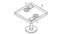
なお、3つの実施の形態において、充電装置1は、図1に示すように、テーブル3の中に埋め込まれているものとする。図1は、充電装置1が2個埋め込まれている例を示しているが、1つのテーブル3に埋め込まれる充電装置1の数は限定されるものではない。 In the three embodiments, it is assumed that the
また、3つの実施の形態においては、図2に示すように、2次電池が装着されるモバイル電子機器は携帯電話4であって、2次電池を格納する電池パック2は、携帯電話4の裏面の凹部4aに装着され、蓋5によって覆われている。また、電池パック2に格納される2次電池はリチウムイオン電池である。
(第1の実施の形態)
本発明の第1の実施の形態の非接触充電型電池システムは、図3に示すように、充電電圧の制御が必要な2次電池であるリチウムイオン電池を格納する電池パック2と、電池パック2に充電電力を供給する充電装置1とを有する。In the three embodiments, as shown in FIG. 2, the mobile electronic device to which the secondary battery is attached is the mobile phone 4, and the
(First embodiment)
As shown in FIG. 3, the non-contact rechargeable battery system according to the first embodiment of the present invention includes a
充電装置1は、充電電力を電磁エネルギとして電磁エネルギ出力部10と、電磁エネルギ出力部10の動作を制御する充電装置側制御部14とを有する。 The
電磁エネルギ出力部10は、商用電源(交流)16を整流する充電装置側整流部11と、充電装置側整流部11で整流された直流電力を商用周波数より高い周波数でスイッチングして交流電力に再変換するスイッチング部12と、スイッチング部12から出力される交流電力を電磁エネルギとして出力する充電装置側コイル部13とを有する。 The electromagnetic
電池パック2は、充電装置側コイル部13が出力する電磁エネルギを充電電力に再変換する再変換部20と、再変換部20から出力される充電電力でリチウムイオン電池24を充電したときの充電電圧を制御(または、充電電圧および充電電流を制御)する電池パック側制御部23とを有する。 The
そして、再変換部20は、充電装置側コイル部13が出力する電磁エネルギを交流電力に変換する電池パック側コイル部21と、この交流電力を直流電力に変換する電池パック側整流部22とを有する。 Then, the
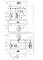
図4は、第1の実施の形態の非接触充電型電池システムの回路図であって、充電装置1は、商用電源16を整流平滑して直流を出力する充電装置側整流部11として機能する充電装置側整流回路61と、充電装置側整流回路61で整流された直流を交流に再変換するスイッチング部12として機能するスイッチング回路62と、スイッチング回路62から出力される交流を電磁エネルギとして出力する充電装置側コイル部13として機能する充電装置側コイル63と、充電装置側コイル63の両端の電圧に応じてスイッチング部12の動作を制御する充電装置側制御部14として機能する充電装置側制御回路64とを有する。 FIG. 4 is a circuit diagram of the contactless rechargeable battery system according to the first embodiment. The
そして、スイッチング回路62は、コレクタが充電装置側整流回路61の正極出力に、エミッタが充電装置側コイル63の一方の端子に接続される充電装置側トランジスタ65と、充電装置側トランジスタ65のベースに所定周期のパルスを印加する発振回路(VCO)66とを有する。 The switching
さらに、充電装置側制御回路64は、充電装置側コイル63両端に発生する電圧に応じて発振回路66の発振周波数を制御する発振制御回路67を有する。 Furthermore, the charging device
なお、本発明にあっては、充電装置1をテーブル3の中に埋め込んでおき、電池パック2を装着した携帯電話4、あるいは携帯電話4から取り外した電池パック2をテーブル3の上に置いたときに充電が行われる。 In the present invention, the charging
電池パック2は、再変換部20として機能する電磁エネルギ変換回路71と、電池パック側制御部23として機能する電圧電流制御回路72と、リチウムイオン電池24とを有する。 The
そして、リチウムイオン電池24は、携帯電話4に装着されたときに、携帯電話に内蔵されている携帯電話回路46に電力を供給するように構成されている。 The
電磁エネルギ変換回路71は、充電装置側コイル63と電磁的に結合する電池パック側コイル部21として機能する電池パック側コイル74と、電池パック側コイル74から出力される交流電力を整流する電池パック側整流部22として機能する電池パック側整流回路75とを有する。 The electromagnetic
電圧電流制御回路72は、コレクタが電池パック側整流回路75の正極端子に、エミッタがリチウムイオン電池24の正極端子に接続される電池パック側トランジスタ76と、リチウムイオン電池24に流入する電流を検出する電流検出抵抗77と、リチウムイオン電池24の温度を検出するサーミスタ78と、リチウムイオン電池24に印加される電圧およびリチウムイオン電池24に流入する電流を電池パック側トランジスタ76により制御するための制御信号を電池パック側トランジスタ76のベースに印加する電圧電流制御IC79とを有する。 The voltage /
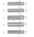
図5(a)〜(e)は、一つの筐体27内にリチウムイオン電池24、電圧電流制御回路72、電池パック側コイル74および電池パック側整流回路75を格納する電池パック2を示すものであり、電池パック2は、携帯電話4に装着した状態でも、また、携帯電話4から取り出した状態でも充電できるよう構成されている。なお、電圧電流制御回路72と電池パック側整流回路75は、同一基板上に配置されているため、図5(a)〜(e)には参照番号72と75とが重ねて示されている。 5A to 5E show the
筐体27およびリチウムイオン電池24の外皮は、交流磁界中に置かれたときに渦電流損を生じて発熱することのない材料、即ち、プラスチック等の絶縁材料で製作することが望ましい。 The casing of the
筐体27内のリチウムイオン電池24、電圧電流制御回路72、電池パック側コイル74および電池パック側整流回路75の配置については、図5(a)〜(e)に示すような種々の配置態様が考えられる。 About arrangement | positioning of the
図5(a)においては、リチウムイオン電池24の一方の面側に電池パック側コイル74を配置し、リチウムイオン電池24の側方に電圧電流制御回路72および電池パック側整流回路75を配置している。 In FIG. 5A, the battery
図5(b)においては、リチウムイオン電池24の一方の面側に電圧電流制御回路72を配置し、電池パック側コイル74および電池パック側整流回路75を配置している。 In FIG. 5B, the voltage /
図5(c)においては、リチウムイオン電池24の一方の面側および他方の面側に一対の電池パック側コイル74を配置し、リチウムイオン電池24の側方に電圧電流制御回路72および電池パック側整流回路75を配置している。 In FIG. 5C, a pair of battery pack side coils 74 are arranged on one surface side and the other surface side of the
図5(d)においては、リチウムイオン電池24の一方の面側に電圧電流制御回路72および電池パック側整流回路75を配置し、電池パック側コイル74を電圧電流制御回路72および電池パック側整流回路75が搭載される基板上にプリントしている。 5D, the voltage /
図5(e)においては、電池パック側コイル74をリチウムイオン電池24の一方の面側に直接プリントし、リチウムイオン電池24の側方に電圧電流制御回路72および電池パック側整流回路75を配置している。 In FIG. 5E, the battery
次に、本発明に係る非接触充電型電池システムの動作を説明する。 Next, the operation of the contactless rechargeable battery system according to the present invention will be described.
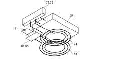
図6は充電装置1の上方に電池パック2を配置したときの斜視図である。まず、商用電源16から供給される交流電力は、充電装置側整流回路61で直流電力に変換され、スイッチング回路62でスイッチングされて、例えば50KHzの高周波の交流電力に変換される。そして、この交流電力は充電装置側コイル63により電磁エネルギに変換され、空中に放射される。 FIG. 6 is a perspective view when the
次に、電池パック2を充電装置1に近づけて、電池パック側コイル74が充電装置側コイル63と電磁的に結合すると、充電装置側コイル63が発生する磁力線は、電池パック側コイル74と交差し、電池パック側コイル74中に交流電力が誘起される。 Next, when the
この交流電力は、電池パック側整流回路75により直流電力に変換されて、電圧電流制御回路72に供給される。 The AC power is converted into DC power by the battery pack
そして、電圧電流制御回路72に含まれる電圧電流制御用IC79(図4参照)は、リチウムイオン電池24を充電する充電電力の電圧および電流を制御する。 A voltage / current control IC 79 (see FIG. 4) included in the voltage /
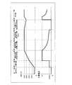
図7は、リチウムイオン電池24の充電シーケンス図である。まず、電圧電流制御用IC79は、リチウムイオン電池24の端子電圧が3.0V以下であると判断したときは充電電流を0.05Cに維持して予備充電を行い、端子電圧が3.0V以上であると判断したときは、充電電流を1Cに維持する定電流充電を行う。なお、予備充電および定電流充電中は、リチウムイオン電池24の端子電圧は徐々に上昇する。 FIG. 7 is a charge sequence diagram of the
次に、電圧電流制御用IC79は、端子電圧が4.2Vに到達したと判断したときは、リチウムイオン電池24に印加する充電電圧を4.2Vに維持する定電圧充電を行う。なお、定電圧充電中は、充電電流は1Cから徐々に減少する。 Next, when the voltage /
電圧電流制御用IC79は、充電電流が0.05Cまで減少したときに、満充電状態となったものと判断してリチウムイオン電池24への充電電力の供給を停止する。 When the charging current decreases to 0.05 C, the voltage /
そして、電圧電流制御用IC79は、リチウムイオン電池24の端子電圧が4.0Vまで低下したと判断したときは、再充電を開始する。 When the voltage /
電圧電流制御用IC79により制御される充電電流の変化に応じて、充電装置側コイル63の両端の電圧は変化するので、充電装置側コイル63の両端の電圧に基づいて充電装置1の動作を制御し、充電装置1の不必要な電磁エネルギの放射を防止することができる。 Since the voltage at both ends of the charging
第1の実施の形態においては、充電装置1の発振制御回路67は、充電装置側コイル63の両端に発生する電圧が、0.05Cの充電電流に対応する閾値電圧未満であるときには、発振回路66を連続発振状態に制御している。閾値電圧以上であれば、発振回路66を停止状態に制御し、発振回路66の停止状態が所定時間以上継続したときにはスタンバイ状態にあることを示すために発振回路66を間欠発振状態に制御している。 In the first embodiment, the
以上説明したように、第1の実施の形態によれば、リチウムイオン電池のように充電電圧を制御する必要のある電池を非接触で充電する充電装置および電池パックの構成を従来より簡略化できることとなる。
(第2の実施の形態)
本発明の第2の実施の形態の非接触充電型電池システムは、電池パック側制御部23の電流制御を省略することにより電池パック内の回路構成をさらに簡略化することを目的とする。As described above, according to the first embodiment, the configuration of the charging device and the battery pack for charging the battery that needs to control the charging voltage, such as the lithium ion battery, in a non-contact manner can be simplified as compared with the related art. It becomes.
(Second Embodiment)
The non-contact chargeable battery system according to the second embodiment of the present invention aims to further simplify the circuit configuration in the battery pack by omitting the current control of the battery pack
即ち、充電装置側コイル63と電池パック側コイル74との間の結合係数kは、[数1]により定義され常に“1.0”以下である。 That is, the coupling coefficient k between the charging

即ち、相互インダクタンスMの最大値は充電装置側コイル63のインダクタンスL1と電池パック側コイル74のインダクタンスL2の相乗平均値であるが、電池パック側コイル74に誘起される交流電力は相互インダクタンスMが大きくなるほど大きくなる。That is, the maximum value of the mutual inductance M is a geometric mean value of the inductance L1 of the charging
従って、充電装置側コイル63および電池パック側コイル74の導体径および巻き数の変更により相互インダクタンスMを適切な値として、電池パック側コイル74に誘起される交流電力から発生する充電電流を1C以下に制限することが可能となる。これにより、電池パック2内の電流制御回路を省略できることとなる。 Therefore, the mutual inductance M is set to an appropriate value by changing the conductor diameter and the number of turns of the charging
図8は第2の実施の形態の非接触充電型電池システムのブロック図であって、電池パック2は、再変換部20と、第2の電池パック側制御部25と、リチウムイオン電池24とを有する。 FIG. 8 is a block diagram of the contactless rechargeable battery system according to the second embodiment. The
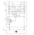
図9は、第2の電池パック側制御部25として機能する電圧制御回路80の回路図であって、コレクタが電池パック側整流回路75の正極端子に、エミッタがリチウムイオン電池24の正極端子に接続される第2の電池パック側トランジスタ81と、リチウムイオン電池24の正極端子および負極端子の間に接続される基準電圧発生回路82と、実電圧検出回路83と、電圧制御増幅器84とを有している。 FIG. 9 is a circuit diagram of the
基準電圧発生回路82は、第1の抵抗85とツェナーダイオード86との直列接続であり、実電圧検出回路83は、第2の抵抗87と第3の抵抗88の直列抵抗である。 The reference
そして、第1の抵抗85とツェナーダイオード86の共通接続点は電圧制御増幅器84の第1の入力端子に接続され、第2の抵抗87と第3の抵抗88との共通接続点は電圧制御増幅器84の第2の入力端子に接続される。 The common connection point of the
以下に、図8および図9を参照しつつ、第2の実施の形態の動作を説明する。 The operation of the second embodiment will be described below with reference to FIGS. 8 and 9.
電池パック2を充電装置1に接近させると、電池パック側コイル74に交流電力が誘起される。 When the
このとき、基準電圧発生回路82で発生する基準電圧を4.2Vに設定すると、すでに説明したように電池パック側コイル74に誘起される交流電力が発生する充電電流は最大でも1Cであるので、リチウムイオン電池24の端子電圧が4.2Vに到達するまでは、充電電流を1Cとする定電流充電が行われる。 At this time, if the reference voltage generated by the reference
リチウムイオン電池24の端子電圧が4.2Vに到達すると、電圧制御増幅器84は、実電圧検出回路83により検出された実電圧と基準電圧発生回路82が発生する基準電圧(4.2V)とを比較し、実電圧と基準電圧の偏差に応じた制御電圧を第2の電池パック側トランジスタ81のベースに供給する。 When the terminal voltage of the
そして、第2の電池パック側トランジスタ81は、ベースに印加される制御電圧に応じて第2の電池パック側トランジスタ81のコレクタからエミッタに向かって流れる電流を制御する。 The second battery
リチウムイオン電池24に流入する充電電流が変化すると、基準電圧発生回路82が発生する基準電圧は一定であるのに対し、実電圧検出回路83により検出される実電圧は変化するので、第2の電池パック側トランジスタ81を流れる電流が制御されてリチウムイオン電池24の端子電圧は基準電圧に維持され、定電圧充電が行われる。 When the charging current flowing into the
なお、前述以外の第2の実施の形態の構成および動作は、第1の実施の形態の構成および動作と同一であるので、重複する記載を省略する。 Since the configuration and operation of the second embodiment other than those described above are the same as the configuration and operation of the first embodiment, duplicate descriptions are omitted.
前述した第2の実施の形態によれば、充電装置側コイル63と電池パック側コイル74とが最も密に結合したときでも充電電流が所定電流以下となるので、電池パック2の回路から電流制御機能を省くことができる。
(第3の実施の形態)
第3の実施の形態は、実際に充電装置側コイル63上に配置された磁性体が電池パック2であるときにだけ、発振回路66が連続発振状態となる構成とする。According to the above-described second embodiment, even when the charging
(Third embodiment)
In the third embodiment, the oscillation circuit 66 is in a continuous oscillation state only when the magnetic material actually arranged on the charging
図10は、第3の実施の形態の非接触充電型電池システムのブロック図であって、電池パック2内に識別信号発信部26が、充電装置1内に識別信号受信部15が追加される。 FIG. 10 is a block diagram of the contactless rechargeable battery system according to the third embodiment, in which an
識別信号発信部26は、リチウムイオン電池24から電力の供給を受けて、予め定められた所定の識別信号を発信し、電池パック2に内蔵される送信アンテナから放射されるように構成されている。なお、電池パック側コイル74を送信アンテナとして使用することもできる。 The identification
識別信号受信部15は、電池パック2が発振する識別信号を受信し、電池パック2が充電装置1の近傍に配置されたことを検出し、充電装置側制御部14に制御信号を出力するように構成されている。なお、充電装置側コイル63を受信アンテナとして使用することもできる。 The identification
次に、第3の実施の形態の動作を説明する。 Next, the operation of the third embodiment will be described.
電池パック2に内蔵される識別信号発信部26は、リチウムイオン電池24から電力の供給を受けて識別信号を常時発信している。 The
電池パック2が充電装置1の充電装置側コイル63上に配置されると、識別信号受信部15は識別信号を受信し、充電装置側制御部14に連続動作指令の出力を要求する。充電装置側制御部14は、識別信号受信部15の要求を受けて、スイッチング部12に連続動作を指令する。そして、充電装置側コイル63から電池パック側コイル74に連続的にエネルギが供給され、リチウムイオン電池24を充電する。 When the
前述したように、第3の実施の形態によれば、充電装置側コイル63上に配置された磁性体が電池パック2であることを確認した後に充電が開始されるので、電池パック2以外の導電体が充電装置側コイル63に配置された場合の不要な充電動作を抑制することができる。 As described above, according to the third embodiment, charging is started after confirming that the magnetic body arranged on the charging
なお、以上では第3の実施の形態を第1の実施の形態に適用した場合について説明したが、第3の実施の形態を第2の実施の形態にも適用できることは明らかである。 Although the case where the third embodiment is applied to the first embodiment has been described above, it is obvious that the third embodiment can also be applied to the second embodiment.
また、充電装置側制御部14のスイッチング部12に対する制御状態を表示するようにすれば、使用者は動作状態を容易に把握できることとなる。 Moreover, if the control state with respect to the switching
例えば、充電装置側制御部14が間欠発信を指令しているときは緑色のLEDをフリッカー点灯し、電池パック2からの識別信号を検出したときは緑色のLEDを連続点灯し、連続動作を指令しているときは赤色のLEDをフリッカー点灯し、充電を完了したときに赤色のLEDを連続点灯し、電池パック2からの識別信号を検出しなくなったときに緑色のLEDをフリッカー点灯に戻すとともに赤色のLEDを消灯してもよい。 For example, when the charging device
以上のように、本発明に係る非接触充電型電池システムは、充電電圧の制御が必要な2次電池用の充電装置の構成および2次電池回りの回路の構成を従来のシステムより簡略化できるという効果を有し、2次電池充電システム等として有効である。 As described above, the contactless rechargeable battery system according to the present invention can simplify the configuration of the charging device for the secondary battery and the configuration of the circuit around the secondary battery that require control of the charging voltage as compared with the conventional system. It is effective as a secondary battery charging system.
1 充電装置
2 電池パック
5 蓋
10 電磁エネルギ出力部
11 充電装置側整流部
12 スイッチング部
13 充電装置側コイル部
14 充電装置側制御部
20 再変換部
21 電池パック側コイル部
22 電池パック側整流部
23 電池パック側制御部
24 リチウムイオン電池DESCRIPTION OF
Claims (10)
Translated fromJapanese前記充電装置が、前記充電電力を電磁エネルギとして出力する電磁エネルギ出力部を有し、
前記電池パックが、前記電磁エネルギを充電電力に再変換する再変換部と、前記再変換された充電電力で前記2次電池を充電したときの充電電圧および充電電流のうち、少なくとも前記充電電圧を制御する制御部とを有することを特徴とする非接触充電型電池システム。A battery pack that stores a secondary battery that requires control of a charging voltage; and a charging device that supplies charging power to the secondary battery;
The charging device has an electromagnetic energy output unit that outputs the charging power as electromagnetic energy,
The battery pack reconverts the electromagnetic energy into charging power, and at least the charging voltage among a charging voltage and a charging current when the secondary battery is charged with the reconverted charging power. A non-contact chargeable battery system comprising a control unit for controlling.
前記再変換部が、前記電磁エネルギを交流電力に変換する電池パック側コイル部と、前記交流電力を直流電力に変換する電池パック側整流部とを有することを特徴とする請求項1に記載の非接触充電型電池システム。The electromagnetic energy output unit is a charging device side rectifying unit that rectifies a commercial power supply, a switching unit that switches power rectified by the charging device side rectifying unit, and a charging device that outputs the switched power as electromagnetic energy. Side coil part,
The said re-conversion part has a battery pack side coil part which converts the said electromagnetic energy into alternating current power, and a battery pack side rectification part which converts the said alternating current power into direct current power, The Claim 1 characterized by the above-mentioned. Non-contact rechargeable battery system.
前記充電装置が、前記識別信号を受信したときに、前記スイッチング部を動作状態に制御する識別信号受信部を有することを特徴とする請求項1または請求項2に記載の非接触充電型電池システム。The battery pack has an identification signal transmission unit that transmits a predetermined identification signal,
The contactless rechargeable battery system according to claim 1, wherein the charging device includes an identification signal receiving unit that controls the switching unit to be in an operating state when the identification signal is received. .
商用電源を整流する整流部と、前記整流部で整流された電力をスイッチングするスイッチング部と、前記スイッチングされた電力を電磁エネルギとして出力するコイル部と、前記コイル部両端の電圧に応じて前記スイッチング部の動作を制御する制御部とを有することを特徴とする充電装置。A charging device that supplies charging power to a secondary battery that requires control of a charging voltage,
A rectifying unit that rectifies commercial power, a switching unit that switches the electric power rectified by the rectifying unit, a coil unit that outputs the switched electric power as electromagnetic energy, and the switching according to a voltage at both ends of the coil unit And a control unit that controls the operation of the unit.
充電装置から供給される電磁エネルギを充電電力に再変換する再変換部と、前記再変換された充電電力で前記2次電池を充電したときの充電電圧および充電電流を制御する制御部とを有することを特徴とする電池パック。A battery pack for storing a secondary battery that requires charge voltage control,
A reconversion unit that reconverts electromagnetic energy supplied from the charging device into charging power; and a control unit that controls a charging voltage and a charging current when the secondary battery is charged with the reconverted charging power. A battery pack characterized by that.
充電装置から供給される電磁エネルギを充電電力に再変換する再変換部と、前記再変換された充電電力で前記2次電池を充電したときの充電電圧を制御する制御部とを有することを特徴とする電池パック。A battery pack for storing a secondary battery that requires charge voltage control,
A reconversion unit that reconverts electromagnetic energy supplied from a charging device into charging power, and a control unit that controls a charging voltage when the secondary battery is charged with the reconverted charging power. Battery pack.
Priority Applications (1)
| Application Number | Priority Date | Filing Date | Title |
|---|---|---|---|
| JP2004297763AJP2006115562A (en) | 2004-10-12 | 2004-10-12 | Non-contact rechargeable battery system, charging device and battery pack |
Applications Claiming Priority (1)
| Application Number | Priority Date | Filing Date | Title |
|---|---|---|---|
| JP2004297763AJP2006115562A (en) | 2004-10-12 | 2004-10-12 | Non-contact rechargeable battery system, charging device and battery pack |
Publications (2)
| Publication Number | Publication Date |
|---|---|
| JP2006115562Atrue JP2006115562A (en) | 2006-04-27 |
| JP2006115562A5 JP2006115562A5 (en) | 2007-11-22 |
Family
ID=36383585
Family Applications (1)
| Application Number | Title | Priority Date | Filing Date |
|---|---|---|---|
| JP2004297763APendingJP2006115562A (en) | 2004-10-12 | 2004-10-12 | Non-contact rechargeable battery system, charging device and battery pack |
Country Status (1)
| Country | Link |
|---|---|
| JP (1) | JP2006115562A (en) |
Cited By (13)
| Publication number | Priority date | Publication date | Assignee | Title |
|---|---|---|---|---|
| WO2008056415A1 (en) | 2006-11-08 | 2008-05-15 | Panasonic Corporation | Non-contact charger, electronic device, battery pack, and non-contact charge system |
| JP2008178194A (en)* | 2007-01-17 | 2008-07-31 | Seiko Epson Corp | Power reception control device, power reception device, and electronic device |
| JP2008206232A (en)* | 2007-02-16 | 2008-09-04 | Seiko Epson Corp | Power transmission control device, power reception control device, non-contact power transmission system, power transmission device, power reception device, and electronic equipment |
| EP2342778A1 (en)* | 2008-09-08 | 2011-07-13 | QUALCOMM Incorporated | Receive antenna arrangement for wireless power |
| JP2011250644A (en)* | 2010-05-29 | 2011-12-08 | Sanyo Electric Co Ltd | Battery pack, battery drive apparatus, charging cradle and charging method of battery pack |
| WO2012019185A3 (en)* | 2010-08-06 | 2012-05-10 | Hpv Technologies, Inc. | Lithium polymer battery charger and methods therefor |
| WO2013031054A1 (en)* | 2011-08-31 | 2013-03-07 | Necカシオモバイルコミュニケーションズ株式会社 | Charging system, electronic apparatus, charge control method, and program |
| CN103081296A (en)* | 2010-09-01 | 2013-05-01 | 日立麦克赛尔株式会社 | Charging unit and electrical equipment equipped with the charging unit |
| JP5316541B2 (en)* | 2008-09-26 | 2013-10-16 | 株式会社村田製作所 | Contactless charging system |
| JP2014017920A (en)* | 2012-07-06 | 2014-01-30 | Sharp Corp | Battery pack |
| JP2014110733A (en)* | 2012-12-04 | 2014-06-12 | Tdk Corp | Wireless power transmission device |
| JP2014241717A (en)* | 2009-02-05 | 2014-12-25 | クゥアルコム・インコーポレイテッドQualcomm Incorporated | Retrofitting wireless power and near-field communication in electronic devices |
| JP2020020800A (en)* | 2006-11-16 | 2020-02-06 | 株式会社半導体エネルギー研究所 | Device |
- 2004
- 2004-10-12JPJP2004297763Apatent/JP2006115562A/enactivePending
Cited By (27)
| Publication number | Priority date | Publication date | Assignee | Title |
|---|---|---|---|---|
| JP2012080772A (en)* | 2006-11-08 | 2012-04-19 | Panasonic Corp | Non-contact battery charger and electronic appliance |
| US9362779B2 (en) | 2006-11-08 | 2016-06-07 | Panasonic Intellectual Property Management Co., Ltd. | Contactless battery charger, electronic device, battery pack, and contactless charging system |
| EP2882070A1 (en) | 2006-11-08 | 2015-06-10 | Panasonic Corporation | Non-contact charger and non-contact charge system |
| JP2010035417A (en)* | 2006-11-08 | 2010-02-12 | Panasonic Corp | Non-contact battery charger and electronic equipment |
| JP2010034080A (en)* | 2006-11-08 | 2010-02-12 | Panasonic Corp | Battery pack and electronic device |
| US8330414B2 (en) | 2006-11-08 | 2012-12-11 | Panasonic Corporation | Contactless battery charger, electronic device, battery pack, and contactless charging system |
| US9407109B2 (en) | 2006-11-08 | 2016-08-02 | Panasonic Intellectual Property Management Co., Ltd. | Contactless battery charger, electronic device, battery pack, and contactless charging system |
| WO2008056415A1 (en) | 2006-11-08 | 2008-05-15 | Panasonic Corporation | Non-contact charger, electronic device, battery pack, and non-contact charge system |
| JP2020020800A (en)* | 2006-11-16 | 2020-02-06 | 株式会社半導体エネルギー研究所 | Device |
| US11656258B2 (en) | 2006-11-16 | 2023-05-23 | Semiconductor Energy Laboratory Co., Ltd. | Radio field intensity measurement device, and radio field intensity detector and game console using the same |
| US11061058B2 (en) | 2006-11-16 | 2021-07-13 | Semiconductor Energy Laboratory Co., Ltd. | Radio field intensity measurement device, and radio field intensity detector and game console using the same |
| JP2008178194A (en)* | 2007-01-17 | 2008-07-31 | Seiko Epson Corp | Power reception control device, power reception device, and electronic device |
| US8054036B2 (en) | 2007-02-16 | 2011-11-08 | Seiko Epson Corporation | Power transmission control device, power reception control device, non-contact power transmission system, power transmission device, power reception device, and electronic instrument |
| JP2008206232A (en)* | 2007-02-16 | 2008-09-04 | Seiko Epson Corp | Power transmission control device, power reception control device, non-contact power transmission system, power transmission device, power reception device, and electronic equipment |
| JP2014239644A (en)* | 2008-09-08 | 2014-12-18 | クゥアルコム・インコーポレイテッドQualcomm Incorporated | Receive antenna arrangement for wireless power |
| US8581542B2 (en) | 2008-09-08 | 2013-11-12 | Qualcomm Incorporated | Receive antenna arrangement for wireless power |
| JP2012502613A (en)* | 2008-09-08 | 2012-01-26 | クゥアルコム・インコーポレイテッド | Receive antenna placement for wireless power |
| EP2342778A1 (en)* | 2008-09-08 | 2011-07-13 | QUALCOMM Incorporated | Receive antenna arrangement for wireless power |
| JP5316541B2 (en)* | 2008-09-26 | 2013-10-16 | 株式会社村田製作所 | Contactless charging system |
| JP2014241717A (en)* | 2009-02-05 | 2014-12-25 | クゥアルコム・インコーポレイテッドQualcomm Incorporated | Retrofitting wireless power and near-field communication in electronic devices |
| JP2011250644A (en)* | 2010-05-29 | 2011-12-08 | Sanyo Electric Co Ltd | Battery pack, battery drive apparatus, charging cradle and charging method of battery pack |
| WO2012019185A3 (en)* | 2010-08-06 | 2012-05-10 | Hpv Technologies, Inc. | Lithium polymer battery charger and methods therefor |
| CN103081296A (en)* | 2010-09-01 | 2013-05-01 | 日立麦克赛尔株式会社 | Charging unit and electrical equipment equipped with the charging unit |
| JPWO2013031054A1 (en)* | 2011-08-31 | 2015-03-23 | Necカシオモバイルコミュニケーションズ株式会社 | Charging system, electronic device, charging control method and program |
| WO2013031054A1 (en)* | 2011-08-31 | 2013-03-07 | Necカシオモバイルコミュニケーションズ株式会社 | Charging system, electronic apparatus, charge control method, and program |
| JP2014017920A (en)* | 2012-07-06 | 2014-01-30 | Sharp Corp | Battery pack |
| JP2014110733A (en)* | 2012-12-04 | 2014-06-12 | Tdk Corp | Wireless power transmission device |
Similar Documents
| Publication | Publication Date | Title |
|---|---|---|
| CN102165667B (en) | Contactless Charging System | |
| KR100566220B1 (en) | Solid state battery charger | |
| JP5111397B2 (en) | Non-contact charging device provided with coil array, non-contact charging system and charging method | |
| US8629651B2 (en) | Portable wireless charging device | |
| US8907618B2 (en) | Contactless cell apparatus | |
| US8129942B2 (en) | Contactless charging method for charging battery | |
| US20120326661A1 (en) | Contactless power receiving device, and contactless charging system | |
| US20140184149A1 (en) | Method in wireless power transmission system, wireless power transmission apparatus using the same, and wireless power receiving apparatus using the same | |
| JP2013502897A (en) | Inductive rechargeable power pack | |
| WO2008056415A1 (en) | Non-contact charger, electronic device, battery pack, and non-contact charge system | |
| JP2006115562A (en) | Non-contact rechargeable battery system, charging device and battery pack | |
| JP2009213294A (en) | Contactless battery charger | |
| JP2016039643A (en) | Power transmission device and radio power transmission system | |
| WO2016042776A1 (en) | Power reception device, non-contact power transmission system, and charging method | |
| WO2007069293A1 (en) | Contactless charging-type battery system, charging device, and battery pack | |
| JP5964303B2 (en) | Battery pack and battery pack charging method | |
| KR20220100557A (en) | Apparatus and method for detecting foreign object in wireless power transmitting system | |
| WO2017064968A1 (en) | Power reception device, electronic apparatus, and power supply system | |
| JPH08126230A (en) | Non-contact type charger | |
| JPH11289679A (en) | Non-contact charging device, non-contact charging system and electronic equipment | |
| JP2004064938A (en) | Charging system | |
| JP2013066982A (en) | Electric tool case adapted for wireless power feeding, and wireless power feeding system including the same | |
| KR100301430B1 (en) | Battery and battery charging system for charging the battery | |
| JPH11191435A (en) | Portable electrical appliance and charging block | |
| JP2004129315A (en) | Noncontact charger |
Legal Events
| Date | Code | Title | Description |
|---|---|---|---|
| A521 | Request for written amendment filed | Free format text:JAPANESE INTERMEDIATE CODE: A523 Effective date:20071003 | |
| A621 | Written request for application examination | Free format text:JAPANESE INTERMEDIATE CODE: A621 Effective date:20071003 | |
| A977 | Report on retrieval | Free format text:JAPANESE INTERMEDIATE CODE: A971007 Effective date:20080807 | |
| A131 | Notification of reasons for refusal | Free format text:JAPANESE INTERMEDIATE CODE: A131 Effective date:20080819 | |
| A02 | Decision of refusal | Free format text:JAPANESE INTERMEDIATE CODE: A02 Effective date:20090106 |