JP2006115137A - Image reading apparatus and method of variable power magnifying therein - Google Patents
Image reading apparatus and method of variable power magnifying thereinDownload PDFInfo
- Publication number
- JP2006115137A JP2006115137AJP2004299460AJP2004299460AJP2006115137AJP 2006115137 AJP2006115137 AJP 2006115137AJP 2004299460 AJP2004299460 AJP 2004299460AJP 2004299460 AJP2004299460 AJP 2004299460AJP 2006115137 AJP2006115137 AJP 2006115137A
- Authority
- JP
- Japan
- Prior art keywords
- lens
- mirror
- image
- optical path
- original
- Prior art date
- Legal status (The legal status is an assumption and is not a legal conclusion. Google has not performed a legal analysis and makes no representation as to the accuracy of the status listed.)
- Pending
Links
- 238000000034methodMethods0.000titleclaimsdescription28
- 230000003287optical effectEffects0.000claimsabstractdescription81
- 238000003384imaging methodMethods0.000claimsdescription16
- 238000006243chemical reactionMethods0.000claimsdescription7
- 238000004904shorteningMethods0.000claimsdescription7
- 230000003247decreasing effectEffects0.000abstractdescription2
- 238000012545processingMethods0.000description21
- 238000010586diagramMethods0.000description12
- 238000003860storageMethods0.000description8
- 238000012937correctionMethods0.000description3
- 239000011521glassSubstances0.000description2
- 238000012546transferMethods0.000description2
- 238000003705background correctionMethods0.000description1
- 230000006835compressionEffects0.000description1
- 238000007906compressionMethods0.000description1
- 230000001276controlling effectEffects0.000description1
- 238000013461designMethods0.000description1
- 230000006866deteriorationEffects0.000description1
- 238000011161developmentMethods0.000description1
- 230000000694effectsEffects0.000description1
- 238000005286illuminationMethods0.000description1
- 238000004519manufacturing processMethods0.000description1
- 210000001747pupilAnatomy0.000description1
- 230000001105regulatory effectEffects0.000description1
- 239000004065semiconductorSubstances0.000description1
- 239000000758substrateSubstances0.000description1
Images


Classifications
- H—ELECTRICITY
- H04—ELECTRIC COMMUNICATION TECHNIQUE
- H04N—PICTORIAL COMMUNICATION, e.g. TELEVISION
- H04N1/00—Scanning, transmission or reproduction of documents or the like, e.g. facsimile transmission; Details thereof
- H04N1/04—Scanning arrangements, i.e. arrangements for the displacement of active reading or reproducing elements relative to the original or reproducing medium, or vice versa
- H04N1/0402—Scanning different formats; Scanning with different densities of dots per unit length, e.g. different numbers of dots per inch (dpi); Conversion of scanning standards
- H04N1/0408—Different densities of dots per unit length
- H04N1/0411—Different densities of dots per unit length in the main scanning direction
- H—ELECTRICITY
- H04—ELECTRIC COMMUNICATION TECHNIQUE
- H04N—PICTORIAL COMMUNICATION, e.g. TELEVISION
- H04N1/00—Scanning, transmission or reproduction of documents or the like, e.g. facsimile transmission; Details thereof
- H04N1/04—Scanning arrangements, i.e. arrangements for the displacement of active reading or reproducing elements relative to the original or reproducing medium, or vice versa
- H04N1/0402—Scanning different formats; Scanning with different densities of dots per unit length, e.g. different numbers of dots per inch (dpi); Conversion of scanning standards
- H04N1/042—Details of the method used
- H04N1/0423—Switching between or selecting from a plurality of optical paths
- H—ELECTRICITY
- H04—ELECTRIC COMMUNICATION TECHNIQUE
- H04N—PICTORIAL COMMUNICATION, e.g. TELEVISION
- H04N1/00—Scanning, transmission or reproduction of documents or the like, e.g. facsimile transmission; Details thereof
- H04N1/04—Scanning arrangements, i.e. arrangements for the displacement of active reading or reproducing elements relative to the original or reproducing medium, or vice versa
- H04N1/0402—Scanning different formats; Scanning with different densities of dots per unit length, e.g. different numbers of dots per inch (dpi); Conversion of scanning standards
- H04N1/042—Details of the method used
- H04N1/0432—Varying the magnification of a single lens group
- H—ELECTRICITY
- H04—ELECTRIC COMMUNICATION TECHNIQUE
- H04N—PICTORIAL COMMUNICATION, e.g. TELEVISION
- H04N1/00—Scanning, transmission or reproduction of documents or the like, e.g. facsimile transmission; Details thereof
- H04N1/04—Scanning arrangements, i.e. arrangements for the displacement of active reading or reproducing elements relative to the original or reproducing medium, or vice versa
- H04N1/0402—Scanning different formats; Scanning with different densities of dots per unit length, e.g. different numbers of dots per inch (dpi); Conversion of scanning standards
- H04N1/042—Details of the method used
- H04N1/0455—Details of the method used using a single set of scanning elements, e.g. the whole of and a part of an array respectively for different formats
- H—ELECTRICITY
- H04—ELECTRIC COMMUNICATION TECHNIQUE
- H04N—PICTORIAL COMMUNICATION, e.g. TELEVISION
- H04N1/00—Scanning, transmission or reproduction of documents or the like, e.g. facsimile transmission; Details thereof
- H04N1/04—Scanning arrangements, i.e. arrangements for the displacement of active reading or reproducing elements relative to the original or reproducing medium, or vice versa
- H04N1/10—Scanning arrangements, i.e. arrangements for the displacement of active reading or reproducing elements relative to the original or reproducing medium, or vice versa using flat picture-bearing surfaces
- H04N1/1013—Scanning arrangements, i.e. arrangements for the displacement of active reading or reproducing elements relative to the original or reproducing medium, or vice versa using flat picture-bearing surfaces with sub-scanning by translatory movement of at least a part of the main-scanning components
- H04N1/1017—Scanning arrangements, i.e. arrangements for the displacement of active reading or reproducing elements relative to the original or reproducing medium, or vice versa using flat picture-bearing surfaces with sub-scanning by translatory movement of at least a part of the main-scanning components the main-scanning components remaining positionally invariant with respect to one another in the sub-scanning direction
- H—ELECTRICITY
- H04—ELECTRIC COMMUNICATION TECHNIQUE
- H04N—PICTORIAL COMMUNICATION, e.g. TELEVISION
- H04N1/00—Scanning, transmission or reproduction of documents or the like, e.g. facsimile transmission; Details thereof
- H04N1/04—Scanning arrangements, i.e. arrangements for the displacement of active reading or reproducing elements relative to the original or reproducing medium, or vice versa
- H04N1/19—Scanning arrangements, i.e. arrangements for the displacement of active reading or reproducing elements relative to the original or reproducing medium, or vice versa using multi-element arrays
- H04N1/191—Scanning arrangements, i.e. arrangements for the displacement of active reading or reproducing elements relative to the original or reproducing medium, or vice versa using multi-element arrays the array comprising a one-dimensional array, or a combination of one-dimensional arrays, or a substantially one-dimensional array, e.g. an array of staggered elements
- H04N1/192—Simultaneously or substantially simultaneously scanning picture elements on one main scanning line
- H04N1/193—Simultaneously or substantially simultaneously scanning picture elements on one main scanning line using electrically scanned linear arrays, e.g. linear CCD arrays
Landscapes
- Engineering & Computer Science (AREA)
- Multimedia (AREA)
- Signal Processing (AREA)
- Facsimile Scanning Arrangements (AREA)
- Editing Of Facsimile Originals (AREA)
- Image Input (AREA)
Abstract
Description
Translated fromJapaneseこの発明は、画像読取装置及び該画像読取装置における変倍方法に係り、例えば、平板状のコンタクトガラス上に原稿を固定して、光源、イメージセンサ、ミラー及び原稿画像を縮小してイメージセンサに結像させるレンズが筐体内に配置されたモジュールを原稿に対してスキャンさせて原稿画像を読み取る方式の画像読取装置及び該画像読取装置における変倍方法に関する。 The present invention relates to an image reading apparatus and a scaling method in the image reading apparatus. For example, an original is fixed on a flat contact glass, and a light source, an image sensor, a mirror, and an original image are reduced to form an image sensor. BACKGROUND OF THE INVENTION 1. Field of the Invention The present invention relates to an image reading apparatus that reads a document image by scanning a document in which a lens having an image forming lens is disposed in a housing, and a scaling method in the image reading apparatus.
従来より、例えば、デジタル複写機やファクシミリの入力部を構成する画像読取装置としてのスキャナは、読み取る原稿の短辺の長さと同一寸法の基板上に光導電膜を形成して画像を読み取る密着型イメージセンサ方式と、原稿に光源から照明光を照射し反射光をミラー及びレンズを介してCCD(Charge Coupled Device)等のイメージセンサ上に結像させる縮小光学系方式とによるものに大別される。
また、縮小光学系方式によるものは、光源、ミラー、レンズ及びイメージセンサを筐体内に配置したモジュールを原稿に対してスキャンさせるモジュール一体方式と、光源及びミラーのみが移動するミラー移動方式とによるものとがある。2. Description of the Related Art Conventionally, for example, a scanner as an image reading apparatus constituting an input unit of a digital copying machine or a facsimile is a close contact type that reads an image by forming a photoconductive film on a substrate having the same size as the short side of a document to be read. The image sensor system and a reduction optical system system that irradiates a document with illumination light from a light source and forms reflected light on an image sensor such as a CCD (Charge Coupled Device) via a mirror and a lens. .
The reduction optical system is based on a module integrated system that scans a document with a light source, a mirror, a lens, and an image sensor arranged in the housing, and a mirror moving system that moves only the light source and the mirror. There is.
しかしながら、高精細な画像データを得ようとすると、いずれの方式でも、単位長さ当りの読取画素数を増加させる必要があった。
画素数を増加させることにより、1画素の面積が小さくなり、出力が低下して、S/N比が悪化するという問題があった。このため、光源の光量を増加させるか、レンズの瞳径を大きくするか、又は読取速度を低下させる必要があった。
また、画素数の増加のために、画像全体のデータ量が膨大となり、画像処理に要する計算量や、必要な記憶容量もが増大化し、処理時間がかかり、コストも嵩むという問題があった。
また、画素数の増加によって、高価な密着型イメージセンサやCCDを必要とし、縮小光学系方式では、高解像度のレンズを必要とし、コストが嵩む上に寸法も大きくなり、小型化が困難になるという問題があった。
このため、ミラー移動方式で、読取画像を拡大する場合には、ミラー、レンズ及びイメージセンサを変位させて、原稿からレンズに到る光路長を短くして、画素数を増加させることなく、画質を向上させる技術が提案されている(例えば、特許文献1参照。)。
By increasing the number of pixels, there is a problem that the area of one pixel is reduced, the output is lowered, and the S / N ratio is deteriorated. For this reason, it is necessary to increase the light quantity of the light source, increase the pupil diameter of the lens, or decrease the reading speed.
In addition, since the number of pixels increases, the amount of data of the entire image becomes enormous, increasing the amount of calculation required for image processing and the necessary storage capacity, increasing the processing time and cost.
In addition, an increase in the number of pixels necessitates an expensive contact type image sensor and CCD, and the reduction optical system requires a high resolution lens, which increases cost and size, making it difficult to reduce the size. There was a problem.
For this reason, when enlarging a read image using the mirror moving method, the mirror, lens, and image sensor are displaced to shorten the optical path length from the document to the lens without increasing the number of pixels. Has been proposed (see, for example, Patent Document 1).
解決しようとする問題点は、上述した従来技術では、光学系を移動させる場合に、ミラー等を光軸に沿って並進移動させるために、比較的狭い範囲でしか倍率の変更ができず、十分に精細度や画質を向上させることができないという点である。 The problem to be solved is that in the above-described prior art, when the optical system is moved, since the mirror and the like are translated along the optical axis, the magnification can be changed only within a relatively narrow range. However, the definition and image quality cannot be improved.
この発明は、上述の事情に鑑みてなされたもので、読取画素数を増加させることなく、かつ、コストを抑制して、必要に応じて十分精細な画像を得ることができる画像読取装置及び該画像読取装置における変倍方法を提供することを目的としている。 The present invention has been made in view of the above circumstances, and an image reading apparatus capable of obtaining a sufficiently fine image as needed without increasing the number of read pixels and suppressing cost, and the image reading apparatus An object of the present invention is to provide a scaling method in an image reading apparatus.
上記課題を解決するために、請求項1記載の発明は、複数の光電変換素子からなるイメージセンサと、読取対象としての原稿の画像を上記イメージセンサの撮像画面上に結像させるレンズと、上記原稿と上記レンズとの間の光路上に配置され、上記原稿側から到来した光を反射して上記レンズへ導く複数のミラーからなるミラー群とを有し、上記原稿の読取位置を走査しながら上記原稿の画像情報を読み取る走査モジュールを備えてなる画像読取装置に係り、上記原稿から上記レンズに到る光路長を変更して、上記イメージセンサの上記撮像画面上に結像される画像の倍率を変更する変倍手段と、上記レンズ又は/及び上記イメージセンサを光軸に沿って変位させて、焦点が合せられた状態で上記イメージセンサの上記撮像画面上に上記原稿の画像を結像させる焦点調整手段とを備え、上記変倍手段は、上記原稿から到来した光が、上記レンズに到達するまでの上記ミラー群における反射回数を減少させて、上記レンズに導かれるように、上記ミラー群を構成する所定のミラーを変位させ、上記原稿から上記レンズに到る光路長を短縮することによって、上記イメージセンサの撮像画面上に結像される画像を拡大することを特徴としている。 In order to solve the above-described problem, an invention according to claim 1 is directed to an image sensor including a plurality of photoelectric conversion elements, a lens that forms an image of a document as a reading target on an imaging screen of the image sensor, and A mirror group including a plurality of mirrors arranged on an optical path between the document and the lens and reflecting light arriving from the document side to guide the lens while scanning the reading position of the document The present invention relates to an image reading apparatus including a scanning module that reads image information of the original, and changes the optical path length from the original to the lens to change the magnification of an image formed on the imaging screen of the image sensor. The magnification changing means for changing the image and the lens or / and the image sensor are displaced along the optical axis so that the original is placed on the imaging screen of the image sensor in a focused state. Focusing means for forming an image, and the scaling means reduces the number of reflections in the mirror group until the light arriving from the original reaches the lens, and is guided to the lens. In addition, the image formed on the imaging screen of the image sensor is enlarged by displacing a predetermined mirror constituting the mirror group and shortening the optical path length from the original to the lens. It is said.
また、請求項2記載の発明は、請求項1記載の画像読取装置に係り、上記変倍手段は、上記所定のミラーを回転させて、該ミラーで反射する光の反射方向を変更させ、上記原稿から到来した光を、回転させたミラーの上記光路に沿って上記レンズ側に配置された所定のミラーに入射させないことによって、上記原稿から上記レンズに到る光路長を短縮させることを特徴としている。 The invention according to claim 2 relates to the image reading apparatus according to claim 1, wherein the scaling unit rotates the predetermined mirror to change a reflection direction of light reflected by the mirror, and The light path length from the original to the lens is shortened by not allowing the light coming from the original to enter the predetermined mirror disposed on the lens side along the optical path of the rotated mirror. Yes.
また、請求項3記載の発明は、請求項1又は2記載の画像読取装置に係り、上記変倍手段は、上記ミラー群を構成する所定のミラーを変位させて上記光路上から退避させ、上記原稿から到来した光を、退避させたミラーの上記光路に沿って上記レンズ側に配置されたミラーに入射させることによって、上記原稿から上記レンズに到る光路長を短縮させることを特徴としている。 A third aspect of the present invention relates to the image reading apparatus according to the first or second aspect, wherein the zooming unit displaces a predetermined mirror constituting the mirror group and retracts it from the optical path. The optical path length from the original to the lens is shortened by causing light arriving from the original to enter the mirror disposed on the lens side along the optical path of the retracted mirror.
また、請求項4記載の発明は、請求項1、2又は3記載の画像読取装置に係り、上記イメージセンサによって得られた画像信号に、間引き処理又は補間処理を施すことによって、画像を電気的に縮小又は拡大することを特徴としている。 According to a fourth aspect of the present invention, there is provided the image reading apparatus according to the first, second or third aspect, wherein the image is obtained by subjecting the image signal obtained by the image sensor to a thinning process or an interpolation process. It is characterized by being reduced or enlarged.
また、請求項5記載の発明は、請求項1乃至4のいずれか1に記載の画像読取装置に係り、上記走査モジュールを所定の走査方向に沿って移動させるモジュール駆動手段を備えてなることを特徴としている。 A fifth aspect of the present invention relates to the image reading apparatus according to any one of the first to fourth aspects, further comprising module driving means for moving the scanning module along a predetermined scanning direction. It is a feature.
また、請求項6記載の発明は、複数の光電変換素子からなるイメージセンサと、読取対象としての原稿の画像を上記イメージセンサの撮像画面上に結像させるレンズと、上記原稿と上記レンズとの間の光路上に配置され、上記原稿側から到来した光を反射して上記レンズへ導く複数のミラーからなるミラー群とを有し、上記原稿の読取位置を走査しながら上記原稿の画像情報を読み取る走査モジュールを備えてなる画像読取装置における変倍方法に係り、上記原稿から上記レンズに到る光路長を変更して、上記イメージセンサの上記撮像画面上に結像される画像の倍率を変更する変倍ステップと、上記レンズ又は/及び上記イメージセンサを光軸に沿って変位させて、焦点が合せられた状態で上記イメージセンサの上記撮像画面上に上記原稿の画像を結像させる焦点調整ステップとを備え、上記変倍ステップでは、上記原稿から到来した光が、上記レンズに到達するまでの上記ミラー群における反射回数を減少させて、上記レンズに導かれるように、上記ミラー群を構成する所定のミラーを変位させ、上記原稿から上記レンズに到る光路長を短縮することによって、上記イメージセンサの撮像画面上に結像される画像を拡大することを特徴としている。 According to a sixth aspect of the present invention, there is provided an image sensor comprising a plurality of photoelectric conversion elements, a lens for forming an image of a document as a reading object on an imaging screen of the image sensor, and the document and the lens. And a mirror group composed of a plurality of mirrors that are arranged on the optical path between them and reflect light coming from the document side and guide it to the lens, and scan the reading position of the document, The present invention relates to a scaling method in an image reading apparatus including a scanning module, and changes a magnification of an image formed on the imaging screen of the image sensor by changing an optical path length from the original to the lens. The magnification step, the lens or / and the image sensor are displaced along the optical axis, and the original is placed on the imaging screen of the image sensor in a focused state. A focus adjustment step for forming an image, and in the scaling step, the number of reflections of the mirror group until the light arriving from the original reaches the lens is reduced and guided to the lens. Further, the predetermined mirror constituting the mirror group is displaced to shorten the optical path length from the original to the lens, thereby enlarging the image formed on the imaging screen of the image sensor. It is said.
また、請求項7記載の発明は、請求項6記載の画像読取装置における変倍方法に係り、上記変倍ステップでは、上記所定のミラーを回転させて、該ミラーで反射する光の反射方向を変更させ、上記原稿から到来した光を、回転させたミラーの上記光路に沿って上記レンズ側に配置された所定のミラーに入射させないことによって、上記原稿から上記レンズに到る光路長を短縮させることを特徴としている。 According to a seventh aspect of the present invention, there is provided a zooming method in the image reading apparatus according to the sixth aspect, wherein in the zooming step, the predetermined mirror is rotated to change the reflection direction of light reflected by the mirror. The optical path length from the original to the lens is shortened by changing the light coming from the original and not entering the predetermined mirror disposed on the lens side along the optical path of the rotated mirror. It is characterized by that.
また、請求項8記載の発明は、請求項6又は7記載の画像読取装置における変倍方法に係り、上記変倍ステップでは、上記ミラー群を構成する所定のミラーを変位させて上記光路上から退避させ、上記原稿から到来した光を、退避させたミラーの上記光路に沿って上記レンズ側に配置されたミラーに入射させることによって、上記原稿から上記レンズに到る光路長を短縮させることを特徴としている。 The invention according to
また、請求項9記載の発明は、請求項6、7又は8記載の画像読取装置における変倍方法に係り、上記イメージセンサによって得られた画像信号に、間引き処理又は補間処理を施すことによって、画像を電気的に縮小又は拡大することを特徴としている。 The invention according to
また、請求項10記載の発明は、請求項6乃至9のいずれか1に記載の画像読取装置における変倍方法に係り、上記走査モジュールを所定の走査方向に沿って移動させるモジュール駆動ステップを備えてなることを特徴としている。 According to a tenth aspect of the present invention, there is provided a zooming method for an image reading apparatus according to any one of the sixth to ninth aspects, further comprising a module driving step for moving the scanning module along a predetermined scanning direction. It is characterized by.
この発明の構成によれば、変倍手段が、原稿からレンズに到る光路長を変更して、イメージセンサに結像される画像の倍率を変更し、この際、原稿から到来した光が、レンズに到達するまでのミラー群における反射回数を減少させて、レンズに導かれるように、ミラー群を構成する所定のミラーを変位させ、光路長を短縮することによって、イメージセンサに結像される画像を拡大するので、読取画素数を増加させることなく、かつ、コストを抑制して、必要に応じて十分精細な画像を得ることができる。
また、例えば、縮小光学系方式の既存の画像読取装置に、所定のミラーを変位させるための変倍手段としての駆動手段を追加すれば良いので、一段とコストを抑制することができる。According to the configuration of the present invention, the scaling unit changes the optical path length from the document to the lens to change the magnification of the image formed on the image sensor. At this time, the light coming from the document is The number of reflections in the mirror group until reaching the lens is reduced, and the predetermined mirror constituting the mirror group is displaced so as to be guided to the lens, thereby forming an image on the image sensor by shortening the optical path length. Since the image is enlarged, it is possible to obtain a sufficiently fine image as necessary without increasing the number of read pixels and suppressing the cost.
In addition, for example, it is only necessary to add a driving unit as a scaling unit for displacing a predetermined mirror to an existing image reading apparatus of a reduction optical system type, so that the cost can be further reduced.
変倍手段が、原稿からレンズに到る光路長を変更して、イメージセンサに結像される画像の倍率を変更し、この際、原稿から到来した光が、レンズに到達するまでのミラー群における反射回数を減少させて、レンズに導かれるように、ミラー群を構成する所定のミラーを変位させ、光路長を短縮して、イメージセンサに結像される画像を拡大することによって、読取画素数を増加させることなく、かつ、コストを抑制して、必要に応じて十分精細な画像を得るという目的を実現した。 The zooming unit changes the optical path length from the document to the lens to change the magnification of the image formed on the image sensor. At this time, the mirror group until the light coming from the document reaches the lens The number of reflections is reduced and the predetermined mirrors constituting the mirror group are displaced so as to be guided to the lens, the optical path length is shortened, and the image formed on the image sensor is enlarged, thereby reading pixels. The purpose of obtaining a sufficiently fine image as needed was realized without increasing the number and suppressing the cost.
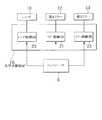
図1は、この発明の第1実施例であるスキャナの読取モジュールの構成を模式的に示す図、図2は、同スキャナの構成を示すブロック図、図3は、同スキャナの概略構成を説明するための説明図、図4は、同読取モジュールの光学系駆動部の構成を示すブロック図、図5は、同光学系駆動部のミラー駆動部の構成を説明するための説明図、図6は、同スキャナのコントローラの構成を示すブロック図、また、図7は、同読取モジュールの動作を説明するための説明図である。 1 is a diagram schematically showing the configuration of a reading module of a scanner according to a first embodiment of the present invention, FIG. 2 is a block diagram showing the configuration of the scanner, and FIG. 3 is a schematic configuration of the scanner. FIG. 4 is a block diagram showing the configuration of the optical system driving unit of the reading module, FIG. 5 is an explanatory diagram for explaining the configuration of the mirror driving unit of the optical system driving unit, and FIG. FIG. 7 is a block diagram showing the configuration of the controller of the scanner, and FIG. 7 is an explanatory diagram for explaining the operation of the reading module.
この例のスキャナ1は、図1乃至図3に示すように、主走査方向Mに沿った読取りを行うと共に、副走査方向Sに沿って移動可能な読取モジュール2と、読取モジュール2のイメージセンサ17へタイミング信号を送るタイミング回路部3と、イメージセンサ17から得られた画像信号を処理する画像処理部4と、読取モジュール2を副走査方向Sに沿って移動させるモジュール駆動部5と、構成各部を制御するコントローラ6と、精細度の切替えや倍率の設定が可能な操作部7と、例えばホストコンピュータに画像データを転送するために用いられる出力インタフェース8とを備えてなっている。なお、図1中、符号9は、原稿Kを載置して固定するためのコンタクトガラスを示す。 As shown in FIGS. 1 to 3, the scanner 1 of this example performs reading along the main scanning direction M and is movable along the sub-scanning direction S, and an image sensor of the reading module 2. A
読取モジュール2は、例えば蛍光灯からなる光源11と、光路上に配置され原稿K側から到来した光を反射してレンズ16へ導くための第1ミラー12、第2ミラー13、第3ミラー14及び第4ミラー15と、原稿Kの画像をイメージセンサ17上に結像させるレンズ16と、リニアCCDアレイからなるイメージセンサ17と、第1ミラー12、第2ミラー13やレンズ16を駆動させて原稿Kからレンズ16に到る光路長を変更し倍率を変更する光学系駆動部18と、光源11や、第1ミラー12、第2ミラー13、第3ミラー14、第4ミラー15、レンズ16、イメージセンサ17及び光学系駆動部18を収納した筐体19とを有してなっている。 The reading module 2 includes a
光学系駆動部18は、図4に示すように、第1ミラー12を回動させるミラー駆動部21と、第2ミラー13を回動させるミラー駆動部22と、レンズ16を光軸に沿って並進移動させるレンズ駆動部23とを有している。
例えば、ミラー駆動部21は、図5に示すように、第1ミラー12の両側部を保持するミラー固定ブラケット25,25と、第1ミラー12を前面側から押えて固定する固定ばね26,26と、筐体19に固定されミラー固定ブラケット25,25を回動させる回動シャフト27と、圧縮ばね等からなる弾性部材28,28,28を介して回動シャフト27に取り付けられた円弧状ラック29と、円弧状ラック29と噛合するピニオン31と、回動範囲を規制するストッパとしての突当部材32,33と、ピニオン31を回動させるステッピングモータ等のアクチュエータ(不図示)とを有してなっている。As shown in FIG. 4, the optical
For example, as shown in FIG. 5, the
ここで、突当部材32,33によって、規制されることによって、第1ミラー12は、それぞれ、所定の回転位置で固定される。また、突当部材32,33は、それぞれ、所定の方向P、Qに沿って変位可能とされ、予め最適位置で固定されるように調整される。
また、ピニオン31は、若干多めに回転制御されて、弾性部材28の変形によって、ミラー固定ブラケット25が確実に突当部材32,33に突き当てられる。
また、ミラー駆動部22は、ミラー駆動部21と略同一の構成とされている。また、レンズ駆動部23は、例えば、レンズ16を保持するレンズ保持体と、歯が光軸に沿って配置されるようレンズ保持体に取り付けられたラックと、ラックと噛合するピニオンと、ピニオンを回動させる駆動モータとを有している。Here, the
Further, the
The
画像処理部4は、A/D変換処理を行った後、階調処理、シェーディング補正処理、MTF(Modulation Transfer Function)補正処理、ガンマ補正処理等と共に、例えば設定された倍率や、精細度切替操作等に基づいて変倍処理を行う。
モジュール駆動部5は、アクチュエータとしてのステッピングモータを有している。
コントローラ6は、図6に示すように、例えば読取モジュール2や画像処理部4を制御する制御部41と、制御部41が実行する処理プログラムや各種データ等を記憶するための記憶部42とを有してなっている。The
The module driving unit 5 has a stepping motor as an actuator.
As shown in FIG. 6, the
制御部41は、CPU(中央処理装置)等からなり、記憶部42に記憶された各種処理プログラムを実行し、スキャナ本体の構成各部を制御する。
制御部41は、記憶部42に記憶されている各種処理プログラムに基づいて、例えば、画像処理部4に変倍処理を実行させたり、光学系駆動部18を構成するミラー駆動部21,22やレンズ駆動部23、モジュール駆動部5を制御するアクチュエータ駆動制御処理等を実行する。
記憶部42は、ROM、RAM等の半導体メモリからなり、各種情報が格納された情報記憶部と、制御部41が実行する各種処理プログラムが格納されるプログラム記憶部とを有している。The
Based on various processing programs stored in the
The
次に、図7を参照して、この例のスキャナ1の動作について説明する。
例えば、写真やフィルム等の読取範囲の狭い小さいサイズの原稿を比較的高密度で読み取りたい場合に、操作者が、操作部7を用いて、比較的高精細度での読取りが可能な高精細モードへの切替え操作を行うと、制御部41は、光学系駆動部18を構成するミラー駆動部21,22やレンズ駆動部23を制御して、図7に示すように、第1ミラー12、第2ミラー13を所定角度回転させて第3ミラー14への原稿Kから到来した反射光の照射を回避させて、光路長を短縮させると共に、レンズ16を光軸に沿ってイメージセンサ17から離れる向きに変位させて、レンズ16とイメージセンサ17との間の距離を調整して、焦点を合わせる。すなわち、イメージセンサ17上に原稿Kの画像を結像させるようにする。Next, the operation of the scanner 1 of this example will be described with reference to FIG.
For example, when it is desired to read a small-size original having a narrow reading range such as a photograph or film at a relatively high density, the operator can use the
これにより、原稿Kから到来した光は、第1ミラー12、第2ミラー13で反射し、第3ミラー14を経由せずに、第4ミラー15に達し、第4ミラー15で反射してレンズ16に導かれ、イメージセンサ17に拡大された画像が結像される。
このように、レンズ16に到達するまでのミラー12,13,14,15における反射回数を減少させて、レンズ16に導かれるように、所定のミラー12,13を回転させ、ミラー14を経由させないようにして、光路長を短縮することによって、イメージセンサ17に結像される画像を拡大する。As a result, the light coming from the document K is reflected by the
In this way, the number of reflections in the
例えば、予め倍率nが設定されている場合は、制御部41は、光学系駆動部18を制御して、ミラー配置を、可能な配置のうち、設定された倍率nに最も近い倍率mに対応する配置として読み取りを行い、画像処理部4を制御して、間引き処理又は前後のデータに基づいて推定して補間データを生成する補間処理を行わせて、n/m倍とする倍率補正処理を行わせる。このようにして、主として光学的に倍率を切り換えて画質劣化のない任意の倍率での画像を得ることができる。
一方、本等の読取範囲の広い大きなサイズの原稿を読み取る場合に、操作者が、操作部7を用いて、通常モードへの切替え操作を行うと、制御部41は、比較的粗い密度で読み取る。For example, when the magnification n is set in advance, the
On the other hand, when the operator performs a switching operation to the normal mode using the
このように、この例の構成によれば、ミラー駆動部21,22が、原稿からレンズ16に到る光路長を変更して、イメージセンサ17に結像される画像の倍率を変更し、ここで、例えば、写真やフィルム等の読取範囲の狭い小さいサイズの原稿を高密度で読み取りたい場合には、原稿から到来した光が、レンズ16に到達するまでのミラー12,13,14,15における反射回数を減少させて、レンズ16に導かれるように、所定のミラー12,13を回転させ、ミラー14を経由させないようにして、光路長を短縮することによって、イメージセンサ17に結像される画像を拡大するので、読取画素数を増加させることなく、必要に応じて十分精細な画像を得ることができる。 Thus, according to the configuration of this example, the
すなわち、比較的高精細に画像の読取りを行う場合には、原稿Kからレンズ16までの光路長を短縮して、最適の縮小光学系としているので、比較的高い画像の鮮鋭度(例えば、MTF)が得られ、十分高い出力が得られるために、高精細で高画質な画像を得ることができる。
ここで、読取画素数を増加させていないので、処理すべきデータ量や必要な記憶容量を抑えることができると共に、高価なCCDや、高解像度のレンズを必要としないため、コストを抑制することができ、かつ、小型化の妨げになることもない。That is, when reading an image with relatively high definition, the optical path length from the document K to the
Here, since the number of read pixels is not increased, the amount of data to be processed and the necessary storage capacity can be suppressed, and an expensive CCD and a high-resolution lens are not required, thereby reducing costs. And does not hinder downsizing.
また、読取画素数を増加させずに、光路長の変更によって光学的に倍率を変更しているので、本等の読取範囲の広い大きなサイズの原稿を読み取る場合には、無駄なデータがなく、光量も十分確保され、光電変換に要する時間も短いため、広範囲を高速に読み取ることができる。
また、例えば、縮小光学系方式の既存の画像読取装置に、所定のミラーを変位させるための変倍手段としてのミラー駆動部21,22を追加すれば良いので、開発コストや製造コストを低減することができるので、一段とコストを抑制することができる。In addition, since the magnification is optically changed by changing the optical path length without increasing the number of read pixels, there is no useless data when reading a large-size document with a wide reading range such as a book, Since a sufficient amount of light is secured and the time required for photoelectric conversion is short, a wide range can be read at high speed.
In addition, for example,
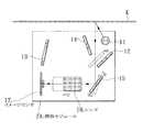
図8は、この発明の第2実施例であるスキャナの読取モジュールの構成を模式的に示す図、また、図9は、同スキャナの動作を説明するための説明図である。
この例が上述した実施例1と大きく異なるところは、第1ミラーを退避させて、第4ミラーを駆動するように構成した点である。
これ以外の構成は、上述した実施例1の構成と略同一であるので、その説明を簡略にする。FIG. 8 is a diagram schematically showing the configuration of the reading module of the scanner according to the second embodiment of the present invention, and FIG. 9 is an explanatory diagram for explaining the operation of the scanner.
This example is greatly different from the first embodiment described above in that the first mirror is retracted and the fourth mirror is driven.
Since the other configuration is substantially the same as the configuration of the first embodiment described above, the description thereof will be simplified.
この例のスキャナの読取モジュール2Aは、図8に示すように、光源11と、光路上に配置され原稿K側から到来した光を反射してレンズ16へ導くための第1ミラー12、第2ミラー13、第3ミラー14及び第4ミラー15と、レンズ16と、リニアCCDアレイからなるイメージセンサ17と、第1ミラー12、第2ミラー13やレンズ16を駆動させて原稿Kからレンズ16に到る光路長を変更し倍率を変更する光学系駆動部18Aと、光源11や、第1ミラー12、第2ミラー13、第3ミラー14、第4ミラー15、レンズ16、イメージセンサ17及び光学系駆動部18Aを収納した筐体19とを有してなっている。 As shown in FIG. 8, the scanner reading module 2 </ b> A of this example includes a
光学系駆動部18は、同図に示すように、第1ミラー12を並進移動させるミラー駆動部51と、第4ミラー15を回動させるミラー駆動部52と、レンズ16を光軸に沿って並進移動させるレンズ駆動部23とを有している。
ミラー駆動部51、ミラー駆動部52は、それぞれ、実施例1で述べたレンズ駆動部23、ミラー駆動部21と同様の構成とされている。As shown in the figure, the optical
The
次に、図9を参照して、この例のスキャナの動作について説明する。
例えば、写真やフィルム等の読取範囲の狭い小さいサイズの原稿を比較的高密度で読み取りたい場合に、操作者が、操作部7を用いて、比較的高精細度での読取りが可能な高精細モードへの切替え操作を行うと、制御部41は、光学系駆動部18Aを構成するミラー駆動部51,52やレンズ駆動部23を制御して、図9に示すように、第1ミラー12を並進移動させて光路上から退避させて、原稿Kから到来した光を、第2ミラー13及び第3ミラー14を経由することなく直接第4ミラー15へ到達させ、かつ、第4ミラー15を所定角度回転させて、原稿Kから到来した光をレンズ16へ向けて反射させて、光路長を短縮させると共に、レンズ16を光軸に沿ってイメージセンサ17から離れる向きに変位させて、レンズ16とイメージセンサ17との間の距離を調整して、焦点を合わせる。
これにより、原稿Kから到来した光は、第4ミラー15で反射し、第1ミラー12、第2ミラー13及び第3ミラー14を経由せずに、第4ミラー15に達し、第4ミラー15で反射してレンズ16に導かれ、イメージセンサ17に拡大された画像が結像される。Next, the operation of the scanner of this example will be described with reference to FIG.
For example, when a small-size original having a narrow reading range such as a photograph or film is to be read at a relatively high density, the operator can use the
As a result, the light coming from the document K is reflected by the
この例の構成によれば、上述した実施例1と略同様の効果を得ることができる。 According to the configuration of this example, substantially the same effect as that of the first embodiment described above can be obtained.
以上、この発明の実施例を図面を参照して詳述してきたが、具体的な構成はこの実施例に限られるものではなく、この発明の要旨を逸脱しない範囲の設計の変更等があってもこの発明に含まれる。
例えば、上述した実施例では、ミラーを4つ設ける場合について述べたが、もちろんこれに限らず、2つとしても良いし、5つ以上設けても良い。また、倍率を2段階に切り替える場合について述べたが、ミラー駆動部を追加して3段階以上に切替え可能としても良い。また、実施例1及び実施例2の構成を組み合わせて、倍率を4段階に切替え可能なようにしても良い。The embodiment of the present invention has been described in detail with reference to the drawings. However, the specific configuration is not limited to this embodiment, and there are design changes and the like without departing from the gist of the present invention. Are also included in the present invention.
For example, in the above-described embodiment, the case where four mirrors are provided has been described. However, the present invention is not limited to this, and two mirrors may be provided, or five or more mirrors may be provided. Further, although the case where the magnification is switched in two stages has been described, a mirror driving unit may be added so that the magnification can be switched in three stages or more. Further, the configurations of the first embodiment and the second embodiment may be combined so that the magnification can be switched in four stages.
また、焦点を合わせるために、レンズを固定してイメージセンサを後方へ移動させるようにしても良いし、レンズとイメージセンサとの両方を互いに離れる向きに移動させるようにしても良い。
また、カラースキャナに対しても適用することができる。
また、出力側が例えばプリンタに接続されている場合は、原稿のサイズと、出力側の印刷用紙のサイズとに基づいて自動的に倍率を設定するように構成しても良い。
また、レンズ駆動部を、レンズ保持体に取り付けたボールねじと、ボールねじを回転させる駆動モータとから構成するようにしても良い。Further, in order to focus, the lens may be fixed and the image sensor may be moved backward, or both the lens and the image sensor may be moved away from each other.
It can also be applied to a color scanner.
Further, when the output side is connected to a printer, for example, the magnification may be automatically set based on the size of the original and the size of the printing paper on the output side.
In addition, the lens driving unit may be configured by a ball screw attached to the lens holder and a drive motor that rotates the ball screw.
光電変換素子として、CCDのほか、フォトダイオードアレイを用いる場合に適用することができる。 The present invention can be applied when a photodiode array is used as the photoelectric conversion element in addition to the CCD.
1 スキャナ(画像読取装置)
2,2A 読取モジュール(走査モジュール)
4 画像処理部
5 モジュール駆動部(モジュール駆動手段)
6 コントローラ
11 光源
12 第1ミラー(ミラー)
13 第2ミラー(ミラー)
14 第3ミラー(ミラー)
15 第4ミラー(ミラー)
16 レンズ
17 イメージセンサ
18,18A 光学系駆動部
19 筐体
21,22,51,52 ミラー駆動部(変倍手段)
23 レンズ駆動部(焦点調整手段)
41 制御部
42 記憶部
K 原稿
1 Scanner (image reading device)
2,2A scanning module (scanning module)
4 Image processing section 5 Module drive section (module drive means)
6
13 Second mirror (mirror)
14 Third mirror (mirror)
15 4th mirror (mirror)
16
23 Lens drive unit (focus adjustment means)
41
Claims (10)
Translated fromJapanese前記原稿から前記レンズに到る光路長を変更して、前記イメージセンサの前記撮像画面上に結像される画像の倍率を変更する変倍手段と、前記レンズ又は/及び前記イメージセンサを光軸に沿って変位させて、焦点が合せられた状態で前記イメージセンサの前記撮像画面上に前記原稿の画像を結像させる焦点調整手段とを備え、
前記変倍手段は、前記原稿から到来した光が、前記レンズに到達するまでの前記ミラー群における反射回数を減少させて、前記レンズに導かれるように、前記ミラー群を構成する所定のミラーを変位させ、前記原稿から前記レンズに到る光路長を短縮することによって、前記イメージセンサの撮像画面上に結像される画像を拡大することを特徴とする画像読取装置。An image sensor composed of a plurality of photoelectric conversion elements; a lens that forms an image of a document as a reading target on an imaging screen of the image sensor; and an optical path between the document and the lens, and the document An image reading apparatus comprising: a mirror group including a plurality of mirrors that reflect light coming from the side and guide the light to the lens, and includes a scanning module that reads image information of the original while scanning the reading position of the original Because
A magnification changing means for changing the magnification of an image formed on the imaging screen of the image sensor by changing an optical path length from the original to the lens, and the lens or / and the image sensor as an optical axis. And a focus adjusting unit that forms an image of the document on the imaging screen of the image sensor in a focused state.
The scaling means reduces the number of reflections in the mirror group until the light arriving from the document reaches the lens and guides the predetermined mirror constituting the mirror group so that the light is guided to the lens. An image reading apparatus that enlarges an image formed on an imaging screen of the image sensor by displacing and shortening an optical path length from the original to the lens.
前記原稿から前記レンズに到る光路長を変更して、前記イメージセンサの前記撮像画面上に結像される画像の倍率を変更する変倍ステップと、前記レンズ又は/及び前記イメージセンサを光軸に沿って変位させて、焦点が合せられた状態で前記イメージセンサの前記撮像画面上に前記原稿の画像を結像させる焦点調整ステップとを備え、
前記変倍ステップでは、前記原稿から到来した光が、前記レンズに到達するまでの前記ミラー群における反射回数を減少させて、前記レンズに導かれるように、前記ミラー群を構成する所定のミラーを変位させ、前記原稿から前記レンズに到る光路長を短縮することによって、前記イメージセンサの撮像画面上に結像される画像を拡大することを特徴とする画像読取装置における変倍方法。An image sensor composed of a plurality of photoelectric conversion elements; a lens that forms an image of a document as a reading target on an imaging screen of the image sensor; and an optical path between the document and the lens, and the document An image reading apparatus comprising: a mirror group including a plurality of mirrors that reflect light coming from the side and guide the light to the lens, and includes a scanning module that reads image information of the original while scanning the reading position of the original A scaling method in
A scaling step of changing the magnification of an image formed on the imaging screen of the image sensor by changing the optical path length from the original to the lens, and the optical axis of the lens or / and the image sensor. And a focus adjustment step of forming an image of the document on the imaging screen of the image sensor in a state where the image sensor is in focus.
In the zooming step, a predetermined mirror constituting the mirror group is guided so that light coming from the document is guided to the lens by reducing the number of reflections in the mirror group until reaching the lens. A scaling method in an image reading apparatus, wherein the image formed on the imaging screen of the image sensor is enlarged by displacing and shortening the optical path length from the original to the lens.
The magnification changing method in the image reading apparatus according to claim 6, further comprising a module driving step for moving the scanning module along a predetermined scanning direction.
Priority Applications (4)
| Application Number | Priority Date | Filing Date | Title |
|---|---|---|---|
| JP2004299460AJP2006115137A (en) | 2004-10-13 | 2004-10-13 | Image reading apparatus and method of variable power magnifying therein |
| US11/247,162US20060077479A1 (en) | 2004-10-13 | 2005-10-12 | Image reading device and method of scaling up or down image to be read |
| CNA2005101136781ACN1761282A (en) | 2004-10-13 | 2005-10-13 | The multiplying power variation of image read-out and this image read-out |
| TW094135674ATWI272836B (en) | 2004-10-13 | 2005-10-13 | Image reading device and method of scaling up or down image to be read |
Applications Claiming Priority (1)
| Application Number | Priority Date | Filing Date | Title |
|---|---|---|---|
| JP2004299460AJP2006115137A (en) | 2004-10-13 | 2004-10-13 | Image reading apparatus and method of variable power magnifying therein |
Publications (1)
| Publication Number | Publication Date |
|---|---|
| JP2006115137Atrue JP2006115137A (en) | 2006-04-27 |
Family
ID=36144923
Family Applications (1)
| Application Number | Title | Priority Date | Filing Date |
|---|---|---|---|
| JP2004299460APendingJP2006115137A (en) | 2004-10-13 | 2004-10-13 | Image reading apparatus and method of variable power magnifying therein |
Country Status (4)
| Country | Link |
|---|---|
| US (1) | US20060077479A1 (en) |
| JP (1) | JP2006115137A (en) |
| CN (1) | CN1761282A (en) |
| TW (1) | TWI272836B (en) |
Cited By (3)
| Publication number | Priority date | Publication date | Assignee | Title |
|---|---|---|---|---|
| JP2008116761A (en)* | 2006-11-06 | 2008-05-22 | Ricoh Co Ltd | Image reading apparatus and image forming apparatus |
| US7729640B2 (en) | 2006-11-17 | 2010-06-01 | Brother Kogyo Kabushiki Kaisha | Carriage for image scanning unit including radiation plate for conducting heat |
| WO2015088255A1 (en)* | 2013-12-12 | 2015-06-18 | Samsung Electronics Co., Ltd. | Zoom lens and image pickup apparatus including the same |
Families Citing this family (11)
| Publication number | Priority date | Publication date | Assignee | Title |
|---|---|---|---|---|
| TWI285497B (en)* | 2002-03-18 | 2007-08-11 | Transpacific Optics Llc | Light source color modulation device and method |
| US8358447B2 (en) | 2007-07-31 | 2013-01-22 | Samsung Electronics Co., Ltd. | Scanner module and image scanning apparatus employing the same |
| EP2395738B1 (en)* | 2007-07-31 | 2016-03-23 | Samsung Electronics Co., Ltd. | Multi-functional device having scanner module and image scanning apparatus employing the scanner module |
| US8379275B2 (en) | 2007-07-31 | 2013-02-19 | Samsung Electronics Co., Ltd. | Scanner module and image scanning apparatus employing the same |
| JP5205084B2 (en)* | 2008-03-11 | 2013-06-05 | 京セラドキュメントソリューションズ株式会社 | Image reading apparatus and image forming apparatus |
| FR2939210B1 (en)* | 2008-12-03 | 2011-04-22 | Sagem Comm | MODULE FOR DYNAMICALLY ADJUSTING THE LENGTH OF AN OPTICAL PATH, TROLLEY, OPTICAL SENSOR AND MULTIFUNCTION SCANNING DEVICE EQUIPPED WITH AT LEAST ONE MODULE AS PREFERRED |
| JP6701867B2 (en)* | 2016-03-25 | 2020-05-27 | 富士ゼロックス株式会社 | Image reading optical system and image reading apparatus |
| JP7057663B2 (en)* | 2017-12-28 | 2022-04-20 | シャープ株式会社 | Image reader and image forming device equipped with it |
| KR102655434B1 (en) | 2019-08-13 | 2024-04-05 | 삼성전자주식회사 | Multi-folded camera and mobile device including the same |
| JP7523282B2 (en)* | 2020-08-18 | 2024-07-26 | シャープ株式会社 | Document feeder and image forming apparatus |
| JP2023145283A (en)* | 2022-03-28 | 2023-10-11 | 富士フイルムビジネスイノベーション株式会社 | Image reading device and image forming system |
Family Cites Families (2)
| Publication number | Priority date | Publication date | Assignee | Title |
|---|---|---|---|---|
| US4402595A (en)* | 1980-03-25 | 1983-09-06 | Canon Kabushiki Kaisha | Scanning type image formation apparatus |
| JP3605665B2 (en)* | 2001-04-25 | 2004-12-22 | 虹光精密工業股▲分▼有限公司 | Multi-resolution image scanning device |
- 2004
- 2004-10-13JPJP2004299460Apatent/JP2006115137A/enactivePending
- 2005
- 2005-10-12USUS11/247,162patent/US20060077479A1/ennot_activeAbandoned
- 2005-10-13CNCNA2005101136781Apatent/CN1761282A/enactivePending
- 2005-10-13TWTW094135674Apatent/TWI272836B/enactive
Cited By (6)
| Publication number | Priority date | Publication date | Assignee | Title |
|---|---|---|---|---|
| JP2008116761A (en)* | 2006-11-06 | 2008-05-22 | Ricoh Co Ltd | Image reading apparatus and image forming apparatus |
| US7729640B2 (en) | 2006-11-17 | 2010-06-01 | Brother Kogyo Kabushiki Kaisha | Carriage for image scanning unit including radiation plate for conducting heat |
| WO2015088255A1 (en)* | 2013-12-12 | 2015-06-18 | Samsung Electronics Co., Ltd. | Zoom lens and image pickup apparatus including the same |
| KR20150068779A (en)* | 2013-12-12 | 2015-06-22 | 삼성전자주식회사 | Zoom lens and image pickup apparatus including the same |
| US9541741B2 (en) | 2013-12-12 | 2017-01-10 | Samsung Electronics Co., Ltd. | Zoom lens and image pickup apparatus including a deformable mirror |
| KR102143631B1 (en)* | 2013-12-12 | 2020-08-11 | 삼성전자주식회사 | Zoom lens and image pickup apparatus including the same |
Also Published As
| Publication number | Publication date |
|---|---|
| TWI272836B (en) | 2007-02-01 |
| US20060077479A1 (en) | 2006-04-13 |
| TW200629879A (en) | 2006-08-16 |
| CN1761282A (en) | 2006-04-19 |
Similar Documents
| Publication | Publication Date | Title |
|---|---|---|
| JP2006115137A (en) | Image reading apparatus and method of variable power magnifying therein | |
| US6233063B1 (en) | Two lens converging device in a dual plane flat-bed scanning system | |
| JP2005101739A (en) | Image reading apparatus adjustment method and image reading apparatus | |
| WO1998059488A1 (en) | Original reader | |
| EP0901272A2 (en) | Single lamp illumination system for a dual plane flat-bed scanner | |
| JP3237616B2 (en) | Image processing apparatus, image processing method, and recording medium | |
| JP2000228712A (en) | Image reader | |
| JPH07503113A (en) | Image input device with optical deflection elements for capturing multiple sub-images | |
| US6762862B2 (en) | High resolution scanner | |
| US6373599B1 (en) | Image scanning apparatus and method | |
| US7518758B2 (en) | Method and apparatus for increasing scanning resolution | |
| CN1164962C (en) | multi-resolution scanning device with automatic focusing function and focusing method thereof | |
| JP2003037712A (en) | Image reading device | |
| JP4089136B2 (en) | Carriage and its adjustment method | |
| JPH118737A (en) | Image input device, image input control device, and recording medium | |
| US7082278B2 (en) | Variable magnification reflecting mirror apparatus | |
| JP2982371B2 (en) | Scanning optical device | |
| JP3160906B2 (en) | Film image reader | |
| JP5000574B2 (en) | Method for adjusting color document reading apparatus | |
| JPH1155460A (en) | Image reading device | |
| JP2002354320A (en) | Imaging device | |
| JP2005033760A (en) | Exposure control apparatus | |
| JPH089109A (en) | Image input device | |
| JP2002006420A (en) | Carriage and image reading apparatus having the same | |
| JP2004177505A (en) | Image reading device |
Legal Events
| Date | Code | Title | Description |
|---|---|---|---|
| A977 | Report on retrieval | Free format text:JAPANESE INTERMEDIATE CODE: A971007 Effective date:20070911 | |
| A131 | Notification of reasons for refusal | Free format text:JAPANESE INTERMEDIATE CODE: A131 Effective date:20070918 | |
| A02 | Decision of refusal | Free format text:JAPANESE INTERMEDIATE CODE: A02 Effective date:20080304 |