JP2006109152A - Connection request device, response device, connection management device, and communication system for communication on network - Google Patents
Connection request device, response device, connection management device, and communication system for communication on networkDownload PDFInfo
- Publication number
- JP2006109152A JP2006109152AJP2004293902AJP2004293902AJP2006109152AJP 2006109152 AJP2006109152 AJP 2006109152AJP 2004293902 AJP2004293902 AJP 2004293902AJP 2004293902 AJP2004293902 AJP 2004293902AJP 2006109152 AJP2006109152 AJP 2006109152A
- Authority
- JP
- Japan
- Prior art keywords
- password
- response
- connection
- network
- request
- Prior art date
- Legal status (The legal status is an assumption and is not a legal conclusion. Google has not performed a legal analysis and makes no representation as to the accuracy of the status listed.)
- Pending
Links
Images


Landscapes
- Data Exchanges In Wide-Area Networks (AREA)
- Small-Scale Networks (AREA)
Abstract
Translated fromJapaneseDescription
Translated fromJapanese本発明は、ネットワーク上でピアツーピア通信を行う機器及び通信システムに関する。 The present invention relates to a device and a communication system that perform peer-to-peer communication on a network.
近年、xDSLや光ファイバーなどのブロードバンド環境が整ったことにより、企業、一般家庭を問わずインターネットが急速に普及してきている。また、パーソナルコンピュータ(PC)だけでなく、テレビやDVDレコーダなどのAV機器や、エアコン、冷蔵庫などのいわゆる白物家電もインターネットに接続できるようになってきている。 In recent years, with the establishment of broadband environments such as xDSL and optical fibers, the Internet has been rapidly spreading regardless of companies and general households. In addition to personal computers (PCs), AV devices such as TVs and DVD recorders, and so-called white goods such as air conditioners and refrigerators can be connected to the Internet.
インターネットに接続された機器間で通信を行う場合には、機器毎に一意に割り当てられたグローバルIPアドレスが使用される。しかし、インターネットに接続する機器の急増により、グローバルIPアドレスの数が不足する傾向にある。そのため、インターネットに直接接続されないローカルエリアネットワーク(以下、「LAN」という。)上の機器においては、RFC1918で規定された、LAN内でのみ一意であるプライベートIPアドレスを使用することが推奨されている。ただし、プライベートIPアドレスはインターネット上では一意ではなく、またその使用が許されていないため、プライベートIPアドレスを有する機器は、そのままではインターネットに接続された他の機器との通信を行うことができない。 When communication is performed between devices connected to the Internet, a global IP address uniquely assigned to each device is used. However, due to the rapid increase in the number of devices connected to the Internet, the number of global IP addresses tends to be insufficient. For this reason, it is recommended that devices on a local area network (hereinafter referred to as “LAN”) that is not directly connected to the Internet use a private IP address defined by RFC 1918 that is unique only within the LAN. . However, since the private IP address is not unique on the Internet and its use is not allowed, a device having a private IP address cannot communicate with other devices connected to the Internet as it is.
そこで、家庭内や企業内のLANからインターネットに接続する場合、Network Address Translation(以下NAT)機能やNetwork Address Port Translation(以下NAPT)機能を有するルータを用いるのが一般的になっている。 Therefore, when connecting to the Internet from a LAN in a home or a company, it is common to use a router having a network address translation (hereinafter referred to as NAT) function or a network address port translation (hereinafter referred to as NAPT) function.
NATもしくはNAPT機能は、プライベートIPアドレスとグローバルIPアドレスの相互変換を行い、LAN上でプライベートIPアドレスが割り当てられた機器が、インターネット上のグローバルIPアドレスが割り当てられた機器と通信を行えるようにするものである。 The NAT or NAPT function performs mutual conversion between a private IP address and a global IP address so that a device assigned a private IP address on the LAN can communicate with a device assigned a global IP address on the Internet. Is.
以下、NAPT機能の仕組みについて、図8〜図10を用いて説明する。なお、家庭内や企業内など同一の建物内のネットワークを示すLANとインターネット(the Internet)等のLAN同士を接続する広域なネットワークとを明確に区別するために、インターネットを含む広域ネットワークを以下「WAN」(Wide Area Network)と表記する。 Hereinafter, the mechanism of the NAPT function will be described with reference to FIGS. In order to clearly distinguish a LAN indicating a network in the same building such as a home or a company and a wide area network connecting the LANs such as the Internet, the wide area network including the Internet is referred to as “ It is written as “WAN” (Wide Area Network).
図8は、家庭内のLANに接続された機器とWANに接続されたサーバとが通信を行うための通信システムの構成の一例を示す図である。図8に示すように、通信システムは、情報を配信するサーバ11と、サーバ11と通信を行う機器12と、NAPT機能を有するルータ104とを備える。また、機器12とルータ104とはLAN106で接続され、LAN106はルータ104によりWAN105と接続されている。 FIG. 8 is a diagram illustrating an example of a configuration of a communication system for communication between a device connected to a home LAN and a server connected to a WAN. As shown in FIG. 8, the communication system includes a
ルータ104は、WAN105とLAN106とに接続されているため、グローバルIPアドレスとプライベートIPアドレスとが割り当てられているが、ここでは、グローバルIPアドレス“202.204.16.255”が割り当てられていると想定する。なお、ルータ104に割り当てられたプライベートIPアドレスに関する説明は、NAPT機能の仕組みの説明に不要であるため省略する。 Since the
同様に、サーバ11にはグローバルIPアドレス“230.74.23.6”が、また、機器12にはプライベートIPアドレス”192.168.1.3”が割り当てられていると想定する。なお、図8に示すように、以下に示す図中に記載された、"["と"]"とで囲まれたIPアドレスは、グローバルIPアドレスを示し、"<"と">"とで囲まれたIPアドレスはプライベートIPアドレスを示すものとする。 Similarly, it is assumed that a global IP address “230.74.23.6” is assigned to the
図9は、機器12がNAPT機能を有するルータ104を介しサーバ11と通信を行う際の通信シーケンスの一例を示す図である。機器12、ルータ104及びサーバ11の間で行われる通信はIPパケット(以下、単に「パケット」ともいう。)をやりとりすることにより行われ、図9に示すように、機器12から送信されたパケット21は、ルータ104によってパケット23に変換され、サーバ11が受信する。さらに、パケット23の応答としてサーバ11から送信されたパケット25は、ルータ104によってパケット27に変換され、機器12が受信する。 FIG. 9 is a diagram illustrating an example of a communication sequence when the
また、図9に示すように、各パケットには、送信元を特定するソースIPアドレス(以下、「SA」という。)と、宛先を指定するディスティネーションIPアドレス(以下、「DA」という。)と、送信元のポート番号であるソースポート(以下、「SP」という。)と、宛先のポート番号であるディスティネーションポート(以下、「DP」という。)と、データ本体であるペイロードとが含まれている。なお、実際に伝送されるパケットには、さらに多くの付加情報が含まれているが、ここでは説明に必要な情報のみを記載している。 Also, as shown in FIG. 9, in each packet, a source IP address (hereinafter referred to as “SA”) for specifying a transmission source and a destination IP address (hereinafter referred to as “DA”) for specifying a destination. Source port number (hereinafter referred to as “SP”), destination port number (hereinafter referred to as “DP”), and payload as data body. It is. Note that a packet that is actually transmitted contains more additional information, but only the information necessary for the explanation is shown here.
ここで、SP及びDPは、通信プロトコルとしてTCP(Transmission Control Protocol)やUDP(User Datagram Protocol)を使用する場合に、パケットに含まれる情報であるが、図9に示す通信シーケンスにおける通信プロトコルはTCPであると想定する。 Here, SP and DP are information included in a packet when TCP (Transmission Control Protocol) or UDP (User Datagram Protocol) is used as a communication protocol, but the communication protocol in the communication sequence shown in FIG. 9 is TCP. Assuming that
機器12が、サーバ11と通信するために、パケット21をルータ104に送信する。パケット21には、発信元である機器12のプライベートIPアドレスであるSA“192.168.1.3”と、機器12とルータ104とが通信を行うためのルータ104のポート番号SP“2000”と、パケットの宛先であるサーバ11のグローバルIPアドレスであるDA“230.74.23.6”と、サーバ11が他の機器と通信を行うためのサーバ11のポート番号DP“1200”とが含まれている。 The
ルータ104は、受け取ったパケット21に往路変換(S22)を施してパケット23とし、宛先であるサーバ11に送信する。往路変換(S22)において、ルータ104は、プライベートIPアドレスであるSA“192.168.1.3”を、ルータ104のグローバルIPアドレスである“202.204.16.255”に置換し、同時にSP“2000”を、ルータ104がサーバ11と通信を行うためののポート番号“3400”に置換する。 The
このとき、ルータ104は、上記の置換を行ったポート番号やグローバルIPアドレス等を相互に対応付けてNAPTテーブルという形式で記憶する。図10は、ルータ104が有するNAPTテーブルの一例を示す図である。 At this time, the
図10に示すように、NAPTテーブルには、LAN機器アドレスとして、機器12のプライベートアドレス“192.168.1.3”が、WANルータアドレスとして、ルータ104のグローバルIPアドレス“202.204.16.255”が、LAN機器ポートとして、ルータ104と機器12とが通信を行うポート番号“2000”が、WANルータポートとして、ルータ104とサーバ11とが通信を行うポート番号“3400”が、それぞれ対応付けられて保存されている。 As shown in FIG. 10, in the NAPT table, the private address “192.168.1.3” of the
さて、サーバ11はパケット23を受け取ると、所定の応答処理(S24)を行った後、パケット23に対する応答として、パケット25をルータ104に送信する。パケット25には、発信元を特定するSA“230.743.23.6”とSP“1200”、及び宛先を示すDA“202.204.16.255”とDP“3400”とが含まれている。 When the
ルータ104は、パケット25を受け取ると、NAPTテーブルを参照し、パケット25に復路変換(S26)を施し、パケット27として機器12に送信する。復路変換(S26)において、ルータ104は、まずNAPTテーブルからDA“202.204.16.255”とDP“3400”との組を参照する。図10に示すように、この組は存在しているので、ルータ104は、DAを“202.204.16.255”から“192.168.1.3”に、DPを“3400”から“2000”に置換する。 Upon receiving the
NAPTテーブルは、その通信が行われている間中は保持され、通信が終了すると破棄される。 The NAPT table is retained during the communication, and is discarded when the communication is completed.
以上の動作により、LAN106上のプライベートIPアドレスを持つ機器12からWAN105上のサーバ11への通信を行うことができる。しかしながら、上述のNAPTテーブルがルータ104に存在しない場合は、サーバ11から機器12へパケットを送達させることができない、つまり、WAN105上のサーバ11からLAN106上のプライベートIPアドレスを持つ機器12への通信を開始することができないこととなる。 Through the above operation, communication from the
そこでこれを解決するために、静的NAPTと呼ばれる機能がある。すなわち、あらかじめ静的なNAPTテーブルをルータ上に設定しておく。内容は、図10のNAPTテーブルと同様であるが、この場合WANルータポートには、設定時に未使用のポート番号を指定しなければならない。静的NAPTを用いると、例えばWAN側の機器から、設定されたグローバルIPアドレスとポート番号とを宛先とするパケットを送信すると、ルータ104は図9と同様に、IPアドレスとポート番号の変換を行うことで、LAN上のプライベートIPアドレスを持つ機器12にパケットが到達することになる。これにより、WAN上の機器からLAN内のプライベートIPアドレスを持つ機器への通信を行えるようになる。 In order to solve this, there is a function called static NAPT. That is, a static NAPT table is set on the router in advance. The contents are the same as those of the NAPT table of FIG. 10, but in this case, an unused port number must be specified for the WAN router port at the time of setting. When static NAPT is used, for example, when a packet destined for the set global IP address and port number is transmitted from a device on the WAN side, the
ところで、ルータのグローバルIPアドレスは常に一定であるとは限らない。例えば、PPP(Point―to―Point Protocol)でインターネットサービスプロバイダと接続していたり、あるいはDHCP(Dynamic Host Configuration Protocol)によりIPアドレスが動的に割り当てられる場合には、インターネットに接続する毎にグローバルIPアドレスが変わることがある。このため、接続先機器のグローバルIPアドレスを把握しておくのは困難となる。また静的NAPTを用いると、通信していない間もLAN上の機器へのアクセスが可能となるため、セキュリティが低くなってしまう。 By the way, the global IP address of the router is not always constant. For example, when connecting to an Internet service provider by PPP (Point-to-Point Protocol) or when an IP address is dynamically assigned by DHCP (Dynamic Host Configuration Protocol), the global IP The address may change. For this reason, it is difficult to know the global IP address of the connection destination device. If static NAPT is used, access to the device on the LAN is possible even during non-communication, and security is lowered.
こうした課題を解決するための通信システムが、特許文献1で提案されている。
特許文献1で提案されている通信システムでは、要求を発行する機器と要求を受け取る機器との間に通信を中継するためのサーバが存在する。要求を受け取る機器は、機器とサーバとの通信に使用するためのグローバルIPアドレスとポート番号とを、機器固有のIDである機器IDに関連づけて、あらかじめ定期的に登録するようにしておく。A communication system for solving these problems is proposed in
In the communication system proposed in
要求を発行する機器は、要求内容と送信先機器の機器IDとをサーバに送信すると、サーバは受け取った機器IDに関連づけられているグローバルIPアドレスとポート番号を持つ機器に対して、要求内容を転送する。要求を受け取る機器がルータを介しサーバと接続されている場合であっても、要求を受け取る機器からは、定期的にパケットが送信されてくるため、ルータに図10に示したようなNAPTテーブルが保存されており、サーバから送信された要求内容を含むパケットは、ルータにより要求を受け取る機器に転送される。 When the device issuing the request transmits the request content and the device ID of the destination device to the server, the server sends the request content to the device having the global IP address and the port number associated with the received device ID. Forward. Even when the device that receives the request is connected to the server via the router, the device that receives the request periodically sends a packet. Therefore, the NAPT table as shown in FIG. The packet that is stored and includes the request content transmitted from the server is transferred by the router to the device that receives the request.
つまり、特許文献1で提案されている通信システムは、2つの機器の間の通信を常にサーバ経由で行うこととなる。そのため、例えば機器間で動画データのように大容量のデータを伝送しようとすると、サーバに多大な負荷がかかるという問題がある。特に複数組の通信が同時に行われると、複数台のサーバで分散処理を行っても対応できない可能性もある。 That is, the communication system proposed in
そこで、互いのグローバルIPアドレスを知らないWAN上の機器間で直接伝送を行う、すなわちピアツーピア通信を行うための情報処理システムが特許文献2で提案されている。 Therefore, Patent Document 2 proposes an information processing system for performing direct transmission between devices on a WAN that do not know each other's global IP address, that is, peer-to-peer communication.
図11は、ピアツーピア通信を行うための情報処理システムの概要を示す図である。図11に示す情報処理システムでは、サーバ3と、端末機器4、端末機器5及び端末機器6のそれぞれとは、WAN105を介して通信を行える。また、サーバ3と端末機器4と端末機器5とはグローバルIPアドレスを有している。端末機器6はグローバルIPアドレスを有するルータ104を介しサーバ3と接続されており、端末機器6自身はグローバルIPアドレスは有さず、プライベートIPアドレスを有している。 FIG. 11 is a diagram illustrating an outline of an information processing system for performing peer-to-peer communication. In the information processing system illustrated in FIG. 11, the
図11に示す情報処理システムでは、端末機器4及び端末機器5は自身のグローバルIPアドレスをサーバ3へ登録し、端末機器6は、ルータ104のグローバルIPアドレスとともに、端末機器6がプライベートIPアドレスを有していることを示す情報をサーバ3へ登録する。 In the information processing system shown in FIG. 11, the
上記登録が行われた状態で、例えば端末機器4は、サーバ3から上記登録情報を取得することにより、端末機器5のグローバルIPアドレスを知ることができる。よって、端末機器4はそのグローバルIPアドレスに接続することにより、端末機器5と直接やり取りすることができる。つまり、端末機器4と端末機器5とはピアツーピア通信を行うことができる。
しかしながら、上述の情報処理システムでは、ピアツーピア通信は、グローバルIPアドレスを有する端末機器同士のみで可能である。グローバルIPアドレスを持たない端末機器6とグローバルIPアドレスを有する端末機器4又は端末機器5とが通信を行う場合は、ピアツーピア通信を行うことができず、常にサーバ3経由で通信が行われる。そのため、例えば、動画データ等の容量の大きなデータを送受信する場合、サーバ3に多大な負荷がかかることとなる。 However, in the above information processing system, peer-to-peer communication is possible only between terminal devices having a global IP address. When the terminal device 6 not having a global IP address and the
また、ネットワークを介してピアツーピア通信を行うということは、ピアツーピア通信を行う機器はネットワーク上の他の機器からの接続を許容している状態であり、不正にアクセスされる危険性がある。しかしながら、上述の情報処理システムでは、端末機器4と端末機器5との間でピアツーピア通信を行う場合に、それぞれの機器において不正アクセスを防ぐための方法は開示されていない。 In addition, performing peer-to-peer communication via a network means that a device that performs peer-to-peer communication permits connection from other devices on the network, and there is a risk of unauthorized access. However, in the above-described information processing system, when peer-to-peer communication is performed between the
そこで、本発明は、このような従来の問題点を鑑みてなされたものであって、互いに異なるネットワーク上にある機器間で、少なくとも一方の機器がグローバルIPアドレスを持たない場合においても、接続相手の機器が正しい機器であることを確認した上でピアツーピア通信を行うことができる機器、それを実現させるための通信管理装置、及び通信システムを提供することを目的とする。 Therefore, the present invention has been made in view of such a conventional problem, and even when at least one device does not have a global IP address between devices on different networks, the connection partner is provided. It is an object to provide a device capable of performing peer-to-peer communication after confirming that the device is a correct device, a communication management device for realizing the device, and a communication system.
上述した課題を解決するために、本発明に関わる通信システムは、第1のネットワークに接続される接続要求機器と、第2のネットワークに接続される応答機器と、前記第1のネットワークと前記第2のネットワークとを接続する第3のネットワークに接続される接続管理装置とを備える通信システムであって、前記接続要求機器は、前記応答機器の識別子と、前記第1のネットワークのグローバルIPアドレスと、前記応答機器との通信に用いるポート番号と、前記応答機器との通信の確立を確認するための第1のパスワードとを前記接続管理装置に送信し、前記接続管理装置は、前記識別子と前記グローバルIPアドレスと前記ポート番号と前記第1のパスワードとを前記接続要求機器から受信し、前記グローバルIPアドレスと前記ポート番号と前記第1のパスワードとを、前記識別子を利用して前記応答機器へ送信し、前記応答機器は、前記グローバルIPアドレスと前記ポート番号と前記第1のパスワードとを前記接続管理装置から受信し、前記第1のパスワードと関連する応答パスワードを、前記グローバルIPアドレスと前記ポート番号とを利用して前記接続要求機器へ送信し、前記接続要求機器は、更に、前記グローバルIPアドレスと前記ポート番号とが利用されて前記応答機器から送信された前記応答パスワードを受信し、(1)受信された前記応答パスワードと前記第1のパスワードとが関連すると判断した場合、前記応答機器との接続を維持し、(2)受信された前記応答パスワードと前記第1のパスワードとが関連しないと判断した場合、前記応答機器との接続を切断する。 In order to solve the above-described problems, a communication system according to the present invention includes a connection request device connected to a first network, a response device connected to a second network, the first network, and the first network. A connection management device connected to a third network for connecting to the second network, wherein the connection requesting device includes an identifier of the response device, a global IP address of the first network, , Transmitting a port number used for communication with the response device and a first password for confirming establishment of communication with the response device to the connection management device, the connection management device including the identifier and the A global IP address, the port number, and the first password are received from the connection requesting device, and the global IP address and the port number are received. The response number is transmitted to the response device using the identifier, and the response device transmits the global IP address, the port number, and the first password from the connection management device. A response password associated with the first password is transmitted to the connection requesting device using the global IP address and the port number, and the connection requesting device further includes the global IP address and the The response password transmitted from the response device using the port number is received. (1) When it is determined that the received response password is related to the first password, the connection to the response device is performed. (2) When it is determined that the received response password and the first password are not related, the response device To cut the connection.
これにより、本発明に関わる通信システムにおいて、接続要求機器は、自身が接続される第1のネットワークのグローバルIPアドレス等を接続管理装置に送信する。このことにより、第2のネットワークに接続される応答機器に対する接続要求を行うことができる。つまり、応答機器がグローバルIPアドレスを有するか否かに関係なく、応答機器への接続要求を行うことができる。 Thereby, in the communication system according to the present invention, the connection requesting device transmits the global IP address of the first network to which it is connected to the connection management device. This makes it possible to make a connection request to the response device connected to the second network. That is, it is possible to make a connection request to the responding device regardless of whether the responding device has a global IP address.
更に、接続管理装置は、接続要求機器から送信される要求先識別子等を受信し、その中から応答機器が接続要求機器に直接接続するために必要な情報を送信することができる。つまり、応答機器と接続要求機器とがピアツーピア通信を開始することを可能なものとしている。 Further, the connection management apparatus can receive a request destination identifier transmitted from the connection requesting device, and can transmit information necessary for the response device to directly connect to the connection requesting device. That is, the response device and the connection requesting device can start peer-to-peer communication.
更に、応答機器は、接続要求機器に直接接続するための情報を受信することができる。つまり、第1のネットワークのグローバルIPアドレスと、前記接続要求機器が前記応答機器との通信に用いる第1のポート番号とを接続管理装置から受信することができ、応答機器は、第1の機器がグローバルIPアドレスを持たない場合であっても接続要求機器に直接接続することができる。また、受信した第1のパスワードに関連する応答パスワードを接続要求機器に送信することにより、応答機器は、自身が正しい機器であることを接続要求機器に確認させることが可能となる。接続要求機器は、応答機器から受信する応答パスワードと自身が送信した第1のパスワードとが関連していると判断した場合に接続を維持する。つまり、接続相手が正しい機器であることを確認した上で接続を維持するため、接続要求機器に対する不正なアクセスを防止することができる。 Further, the response device can receive information for directly connecting to the connection requesting device. That is, the global IP address of the first network and the first port number used by the connection requesting device for communication with the response device can be received from the connection management device, and the response device is the first device. Even if it does not have a global IP address, it can connect directly to the connection requesting device. In addition, by transmitting a response password related to the received first password to the connection requesting device, the response device can make the connection requesting device confirm that it is the correct device. The connection requesting device maintains the connection when it is determined that the response password received from the response device is related to the first password transmitted by itself. That is, since the connection is maintained after confirming that the connection partner is the correct device, unauthorized access to the connection request device can be prevented.
以上の各機器の動作により、本発明に関わる通信システムにおいて、接続管理装置が接続要求機器からの応答機器に対する接続要求を仲介することで、応答機器は接続管理装置へ直接接続するための情報を取得することができ、接続要求機器と応答機器とがピアツーピア通信を開始することが可能となる。また、接続要求機器が、接続相手が応答機器であることを確認した上でピアツーピア通信を行なうため、接続要求機器に対する不正なアクセスを防止できる。 By the operation of each device described above, in the communication system according to the present invention, the connection management device mediates a connection request from the connection requesting device to the response device, so that the response device obtains information for directly connecting to the connection management device. The connection requesting device and the response device can start peer-to-peer communication. In addition, since the connection requesting device performs peer-to-peer communication after confirming that the connection partner is a response device, unauthorized access to the connection requesting device can be prevented.
また、本発明に関わる接続要求機器は、第1のネットワークに接続され、第2のネットワークに接続される応答機器に接続を要求する接続要求機器であって、前記応答機器の識別子と、前記第1のネットワークのグローバルIPアドレスと、前記接続要求機器が前記応答機器との通信に用いるポート番号と、前記応答機器からの接続を確認するための第1のパスワードとを、前記第1のネットワークと前記第2のネットワークとを接続する第3のネットワークに接続される接続管理装置へ送信する第1送信手段と、前記グローバルIPアドレスと前記ポート番号とが利用されて前記応答機器から送信される応答パスワードを受信する第1受信手段と、前記第1送信手段が送信した前記第1のパスワードと前記第1受信手段が受信した前記応答パスワードとが関連するか否かを判断する判断手段と、前記判断手段が、(1)前記応答パスワードと前記第1のパスワードとが関連すると判断した場合、前記応答機器との接続を前記第1送信手段及び前記第1受信手段に維持させ、(2)前記応答パスワードと前記第1のパスワードとが関連しないと判断した場合、前記応答機器との接続を前記第1送信手段及び前記第1受信手段に切断させる通信制御手段とを備える。 The connection request device according to the present invention is a connection request device that is connected to the first network and requests a response device connected to the second network to connect to the identifier, A global IP address of one network, a port number used by the connection requesting device for communication with the response device, and a first password for confirming a connection from the response device; A first transmission means for transmitting to a connection management device connected to the third network for connecting to the second network, and a response transmitted from the response device using the global IP address and the port number. A first receiving means for receiving a password; the first password sent by the first sending means; and the response received by the first receiving means. A determination means for determining whether or not a password is related; and (1) if the determination means determines that the response password and the first password are related, a connection with the response device is made in the first (2) when it is determined that the response password and the first password are not related, a connection with the response device is established by the first transmission unit and the first reception unit. Communication control means for causing the means to disconnect.
これにより、本発明に関わる接続要求機器は、自身が接続される第1のネットワークのグローバルIPアドレス等を接続管理装置に送信する。このことにより、第2のネットワークに接続される応答機器に対する接続要求を行うことができる。つまり、応答機器がグローバルIPアドレスを有するか否かに関係なく、応答機器への接続要求を行うことができる。また、応答機器から受信する応答パスワードと自身が送信した第1のパスワードとが関連していると判断した場合に接続を維持する。つまり、接続相手が正しい機器であることを確認した上で接続を維持するため、接続要求機器に対する不正なアクセスを防止することができる。 Thereby, the connection request apparatus according to the present invention transmits the global IP address of the first network to which the connection request apparatus is connected to the connection management apparatus. This makes it possible to make a connection request to the response device connected to the second network. That is, it is possible to make a connection request to the responding device regardless of whether the responding device has a global IP address. The connection is maintained when it is determined that the response password received from the response device is related to the first password transmitted by the response device. That is, since the connection is maintained after confirming that the connection partner is the correct device, unauthorized access to the connection request device can be prevented.
また、本発明に関わる第接続管理装置は、接続要求機器が接続される第1のネットワークと応答機器が接続される第2のネットワークとを接続する第3のネットワークに接続される接続管理装置であって、前記応答機器の識別子である要求先識別子と、前記第1のネットワークのグローバルIPアドレスと、前記接続要求機器が前記応答機器との通信に用いる第1のポート番号と、前記接続要求機器が前記応答機器からの接続を確認するための第1のパスワードとを前記接続要求機器から受信する第3受信手段と、前記グローバルIPアドレスと前記第1のポート番号と前記第1のパスワードとを前記要求先識別子を利用して前記応答機器に送信する第3送信手段を備える。 A connection management device according to the present invention is a connection management device connected to a third network that connects a first network to which a connection requesting device is connected and a second network to which a response device is connected. A request destination identifier which is an identifier of the response device, a global IP address of the first network, a first port number used by the connection request device for communication with the response device, and the connection request device. Receiving a first password for confirming the connection from the response device from the connection requesting device, the global IP address, the first port number, and the first password. Third transmission means for transmitting to the response device using the request destination identifier is provided.
これにより、接続管理装置は、接続要求機器から送信される要求先識別子等を受信し、その中から応答機器が接続要求機器に直接接続するために必要な情報を送信することができる。つまり、応答機器と接続要求機器とがピアツーピア通信を開始することを可能なものとしている。 As a result, the connection management apparatus can receive a request destination identifier transmitted from the connection requesting device, and can transmit information necessary for the response device to directly connect to the connection requesting device. That is, the response device and the connection requesting device can start peer-to-peer communication.
また、本発明に関わる応答機器は、第2のネットワークに接続され、第1のネットワークに接続される接続要求機器からの接続の要求に応答する応答機器であって、前記第1のネットワークのグローバルIPアドレスと、前記接続要求機器が前記応答機器との通信に用いる第1のポート番号と、前記接続要求機器が前記応答機器からの接続を確認するための第1のパスワードとを、前記第1のネットワークと前記第2のネットワークとを接続する第3のネットワークに接続される接続管理装置から受信する第2受信手段と、前記第1のパスワードと関連する応答パスワードを、前記グローバルIPアドレスと前記第1のポート番号とを利用して前記接続要求機器へ送信する第2送信手段とを備える。 A response device according to the present invention is a response device connected to a second network and responding to a connection request from a connection request device connected to the first network, and is a global device of the first network. An IP address, a first port number used by the connection requesting device for communication with the response device, and a first password for the connection requesting device to confirm a connection from the response device, the first password Second receiving means for receiving from a connection management device connected to a third network for connecting the second network and the second network, a response password associated with the first password, the global IP address and the Second transmission means for transmitting to the connection requesting device using a first port number.
これにより、本発明に関わる応答機器は、接続要求機器に直接接続するための情報を受信することができる。 Thus, the response device according to the present invention can receive information for directly connecting to the connection requesting device.
つまり、第1のネットワークのグローバルIPアドレスと、前記接続要求機器が前記応答機器との通信に用いる第1のポート番号とを接続管理装置から受信することができ、応答機器は、第1の機器がグローバルIPアドレスを持たない場合であっても接続要求機器に直接接続することができる。また、受信した第1のパスワードに関連する応答パスワードを接続要求機器に送信することにより、応答機器は、自身が正しい機器であることを接続要求機器に確認させることが可能となる。 That is, the global IP address of the first network and the first port number used by the connection requesting device for communication with the response device can be received from the connection management device, and the response device is the first device. Even if it does not have a global IP address, it can connect directly to the connection requesting device. In addition, by transmitting a response password related to the received first password to the connection requesting device, the response device can make the connection requesting device confirm that it is the correct device.
本発明は、互いに異なるネットワーク上にある機器間で、少なくとも一方の機器がグローバルIPアドレスを持たない場合においても、接続相手の機器が正しい機器であることを確認した上でピアツーピア通信を行うことができる機器、それを実現させるための通信管理装置、及び通信システムを提供することができる。 According to the present invention, peer-to-peer communication can be performed between devices on different networks even when at least one device does not have a global IP address after confirming that the connected device is the correct device. It is possible to provide a device capable of realizing the communication, a communication management device for realizing the device, and a communication system.
以下に、本発明の実施の形態を図面を参照して説明する。 Embodiments of the present invention will be described below with reference to the drawings.
(実施の形態1)
以下、本発明の実施の形態1について、図1から図5を用いて説明する。(Embodiment 1)
Hereinafter,
先ず、本発明の実施の形態1における通信システム1の構成を図1及び図2を用いて説明する。 First, the structure of the
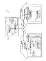
図1は、本発明の実施の形態1における通信システム1のハードウェア構成図である。通信システム1はネットワークで接続される機器間でピアツーピア通信を行わせるための通信システムである。通信システム1は、サーバ101と、WAN105と、ルータ104aと、LAN106aと、要求発行機器102と、ルータ104bと、要求受諾機器103と、LAN106bとを備える。 FIG. 1 is a hardware configuration diagram of a
図1に示すように、サーバ101とルータ104a及びルータ104bとはWAN105で接続されている。また、ルータ104aと要求発行機器102とはLAN106aで接続され、ルータ104bと要求受諾機器103とはLAN106bで接続されている。つまり、サーバ101と要求発行機器102とはWAN105及びルータ104aを介して接続され、サーバ101と要求受諾機器103とはWAN105及びルータ104bを介して接続されている。 As shown in FIG. 1, the
サーバ101は、本発明の接続管理装置の一例であり、要求発行機器102と要求受諾機器103とをピアツーピア接続させるための装置である。 The
WAN105は、本発明の通信システムにおける第3のネットワークの一例であり、インターネットに代表される、LAN間を接続する広域ネットワークである。 The
ルータ104aはNAPT機能を備え、グローバルIPアドレスとプライベートIPアドレスとを相互変換することにより、プライベートIPアドレスを有する要求発行機器102とグローバルIPアドレスを有するサーバ101との通信を中継する機器である。 The
要求発行機器102は、本発明の接続要求機器の一例であり、要求受諾機器103に対して接続を要求する機器である。LAN106aは、本発明の通信システムにおける第1のネットワークの一例であり、上述のようにルータ104aと要求発行機器102とを接続するネットワークである。 The
ルータ104bはルータ104aと同様のNAPT機能を備え、プライベートIPアドレスを有する要求受諾機器103とグローバルIPアドレスを有するサーバ101との通信を中継する機器である。 The
要求受諾機器103は、本発明の応答機器の一例であり、要求発行機器102からの接続要求に対応する機器である。LAN106bは、本発明の通信システムにおける第2のネットワークの一例であり、上述のようにルータ104bと要求受諾機器103とを接続するネットワークである。 The
通信システム1は、上述のようにネットワークで接続される機器間でピアツーピア通信を行わせるための通信システムであり、要求発行機器102と要求受諾機器103とはサーバ101を介することなくデータの送受信を行うことができる。つまり、大容量のデータの送受信を伴う通信であっても、サーバ101に負荷を掛けることがない。そのため、例えば、動画データを再生する動画蓄積機器と動画データを蓄積する動画再生機器とがピアツーピア通信を行ない、動画再生機器に動画データを動画蓄積機器から直接取得させるための動画配信システム等に適用できる。 The
図2は、通信システム1の機能的な構成を示す機能ブロック図である。通信システム1は上述のように、サーバ101と、WAN105と、ルータ104aと、LAN106aと、要求発行機器102と、ルータ104bと、要求受諾機器103と、LAN106bとを備える。 FIG. 2 is a functional block diagram showing a functional configuration of the
サーバ101は、上述のように要求発行機器102と要求受諾機器103とをピアツーピア接続させるための装置であり、要求発行機器102とWAN105及びルータ104aを介して接続することができ、要求受諾機器103とWAN105及びルータ104bを介して接続することができる。サーバ101は、サーバ側通信部110と、機器IDリスト保管部111と、検索部112とを備える。 The
サーバ側通信部110は、要求発行機器102から送信される要求受諾機器103への接続要求を受信し、要求受諾機器103が要求発行機器102へ直接接続するための情報を要求受諾機器103へ送信する処理部である。サーバ側通信部110は本発明の接続管理装置における第3送信手段及び第3受信手段が備える機能を実現する処理部である。 The server-
機器IDリスト保管部111は、要求受諾機器103を識別する機器IDと、サーバ101が要求受諾機器103に情報を送信するために必要な情報とを対応付けて機器IDリストとして保管するための記憶装置である。検索部112は、受信した機器IDから要求受諾機器103に情報を送信するために必要な情報を、機器IDリスト保管部111に保管された機器IDリストの中から検索する処理部である。 The device ID
要求発行機器102は、上述のように要求受諾機器103に対して接続を要求する機器であり、ルータ104a及びWAN105を介してサーバ101に接続される。要求発行機器102は、要求側通信部120と、パスワード生成部121と、入力部122と、判断部123と、通信制御部124とを備える。 The
要求側通信部120は、サーバ101又は要求受諾機器103と情報のやり取りを行う処理部である。要求側通信部120は本発明の接続要求機器における第1送信手段及び第1受信手段が備える機能を実現する処理部である。パスワード生成部121は、ピアツーピア通信を行う通信相手を確認するためのパスワードとして乱数を生成する処理部である。パスワード生成部121は、要求受諾機器103への接続の要求を行う毎に乱数であるパスワードを生成する。つまり、要求を行う毎に使い捨てられる使い捨てパスワードを生成する。 The request
入力部122は、要求発行機器102を使用するユーザが要求発行機器102に対して情報を入力するための処理部である。判断部123は、ピアツーピア通信を行う通信相手から送信されたパスワードが、パスワード生成部121が生成したパスワードと一致するか否かの判断を行う処理部である。通信制御部124は、判断部123の判断に基づき、要求側通信部120に通信の維持又は切断を行わせる処理部である。 The
要求受諾機器103は、上述のように要求発行機器102からの接続要求に対応する機器であり、ルータ104b及びWAN105を介してサーバ101と接続される。要求受諾機器103は、受諾側通信部130と、機器ID保管部132とを備える。 The
受諾側通信部130は、サーバ101又は要求発行機器102と情報のやり取りを行う処理部である。受諾側通信部130は本発明の応答機器における第2送信手段及び第2受信手段が備える機能を実現する処理部である。サーバ101から受信する要求発行機器102からの接続要求に応答するための処理を行う処理部である。機器ID保管部132は、要求受諾機器103に予め付与された識別子である機器IDを保管するための記憶装置である。 The accepting
図2に示すように、通信システム1を構成する各機器は、グローバルIPアドレスまたはプライベートIPアドレスを有しており、サーバ101はグローバルIPアドレスである“230.74.23.6”を、要求発行機器102はプライベートIPアドレスである“192.168.1.11”を、要求受諾機器103はプライベートIPアドレスである“192.168.1.3”を、ルータ104aはグローバルIPアドレスである“4.17.206.2”を、ルータ104bはグローバルIPアドレスである“202.204.16.255”をそれぞれ有していると想定する。 As shown in FIG. 2, each device constituting the
なお、ルータ104a及びルータ104bが有するグローバルIPアドレスは、WAN105上のサーバ101と通信を行う際に使用するものであり、それぞれ、以下「WAN側IPアドレス」ともいう。また、ルータ104a及びルータ104bはそれぞれ、サーバ101と通信を行うためのポート番号を有するが、それらポート番号も、以下「WAN側ポート番号」ともいう。 Note that the global IP addresses possessed by the
次に、以上のように構成された通信システム1の動作を図3から図5を用いて説明する。 Next, the operation of the
図3は、通信システム1における各機器間での通信シーケンスの一例を示す図である。なお、要求受諾機器103は、機器ID保管部132に機器ID“2133”を保管しているものとする。また、図中の「○」は、ルータ104a又はルータ104bにおいて、NAPT機能により、パケットに対するIPアドレス及びポート番号の変換が行われていることを示す。 FIG. 3 is a diagram illustrating an example of a communication sequence between devices in the
要求受諾機器103は、あらかじめ機器ID“2133”を含む機器登録パケットを、要求側通信部120からサーバ101にUDPを用いて送信する(S201)。 The
機器登録パケットはUDPパケットであるため、要求受諾機器103から送信された時点では、付加情報(UDPヘッダ)として要求受諾機器103のプライベートIPアドレスとポート番号が付加されているが、ルータ104bを通過する際にNAPT機能によって、プライベートIPアドレスとポート番号とが、ルータ104bが有するグローバルIPアドレスと、ルータ104bがサーバ101と通信を行うポート番号とに変換される。 Since the device registration packet is a UDP packet, the private IP address and port number of the
要求受諾機器103は上記機器登録パケットを周期的もしくは必要に応じてサーバ101へ送信する。 The
サーバ101では、サーバ側通信部110が機器登録パケットを受信し、機器登録パケットに含まれる要求受諾機器103の機器ID、及び要求受諾機器103が接続されるルータ104bのグローバルIPアドレスとポート番号との組を対応づけ、図4に示す機器IDリストとして、機器IDリスト保管部111に保管する(S202)。 In the
要求受諾機器103は、周期的もしくは必要に応じて機器登録パケットをサーバ101に送信するため、ルータ104bのWAN側IPアドレスもしくはWAN側ポート番号が変更になった場合でも、自動的に更新される。 Since the
つまり、サーバ101は機器IDリスト保管部111に保管されている機器IDリストを参照することにより、任意のタイミングでサーバ101から要求受諾機器103へパケットを送信することができる。 That is, the
要求発行機器102が要求受諾機器103との通信を行う場合、要求側通信部120は、パスワード生成部121で生成された乱数である使い捨てパスワードと、ユーザによって入力部122から入力された要求受諾機器103の機器ID“2133”とを取得する。 When the
要求側通信部120は、機器IDの取得後、まずサーバ101へのTCP接続を行い(S203)、接続要求パケットAをサーバ101に送信する(S204)。接続要求パケットAには、要求受諾機器103の機器ID、要求受諾機器103との通信に用いるグローバルIPアドレスとポート番号、及び使い捨てパスワードが含まれている。 After acquiring the device ID, the request
ここで、接続要求パケットAに含まれる、グローバルIPアドレス及びポート番号は、それぞれルータ104aのWAN側IPアドレス及びWAN側ポート番号であり、要求受諾機器103が要求発行機器102へ直接接続するためのグローバルIPアドレス及びポート番号である。 Here, the global IP address and the port number included in the connection request packet A are the WAN-side IP address and the WAN-side port number of the
図5は、接続要求パケットAをサーバ101へ送信した後のルータ104aが有するNAPTテーブルの一例を示す図である。 FIG. 5 is a diagram illustrating an example of a NAPT table included in the
図5に示すNAPTテーブルの1行目は、要求発行機器102がサーバ101と通信を行うための変換情報である。この変換情報は要求発行機器102が送信した接続要求パケットAがルータ104aを通過する際にルータ104aにより決定され、WANルータアドレスとWANルータポートとが、接続要求パケットAの付加情報(TCPヘッダ)として付加される。なお、WANルータアドレスはルータ104aのWAN側IPアドレスであり、WANルータポートはルータ104aのWAN側ポート番号である。 The first line of the NAPT table shown in FIG. 5 is conversion information for the
図5に示すNAPTテーブルの2行目は、要求発行機器102が要求受諾機器103からのTCP接続を受け付けるための変換情報である。WANルータアドレス“4.17.206.2”と、WANルータポート“5000”とが接続要求パケットAのペイロードに含まれている。これらWANルータアドレス及びWANルータポートの値は、接続要求パケットAの送信前に、要求側通信部120がルータ104aから取得し、接続要求パケットAに含ませる。 The second line of the NAPT table shown in FIG. 5 is conversion information for the
上記のグローバルIPアドレス“4.17.206.2”、ポート番号“5000”に対してTCP接続がなされた場合、それらグローバルIPアドレス及びポート番号がそれぞれ、ルータ104aのNAPT機能により図5のNAPTテーブルの2行目に示すLAN機器アドレス“192.168.1.11”及びLANルータポート“1600”に変換され、要求発行機器102に対してTCP接続を行うことができる。 When the TCP connection is made to the global IP address “4.17.2020.2” and the port number “5000”, the global IP address and the port number are assigned to the NAPT in FIG. 5 by the NAPT function of the
サーバ101では、サーバ側通信部110が接続要求パケットAを受信し、検索部112が、接続要求パケットAに含まれている接続要求先の機器ID“2133”により、機器IDリスト保管部111に保管されている図4に示す機器IDリストを検索する(S205)。 In the
検索部112は、機器ID“2133”に関連づけられているIPアドレス“202.204.16.255”とポート番号“3400”とを機器IDリストから抽出し、サーバ側通信部110が、それらIPアドレス“202.204.16.255”とポート番号“3400”とを宛先として、接続要求通知パケットをUDPを用いて送信する(S206)。つまり、接続要求通知パケットが要求受諾機器103へ送信される。接続要求通知パケットは接続要求があったことを要求受諾機器103に通知するためのパケットである。 The
接続要求通知パケットは、機器登録パケットに対する応答としてルータ104bに送信されるため、ルータ104bでIPアドレスとポート番号の変換が行われ、要求受諾機器103に到達できる。 Since the connection request notification packet is transmitted to the
要求受諾機器103は、接続要求通知パケットを受け取ると、受諾側通信部130がサーバ101に対してTCP接続を行う(S207)。 When the
サーバ101は、要求受諾機器103からのTCP接続を受諾すると、TCP接続を介して接続要求パケットBを要求受諾機器103に送信する(S208)。接続要求パケットBには、サーバ101が要求発行機器102から受信した接続要求パケットAに含まれている、要求発行機器102が要求受諾機器103と通信を行うためのグローバルIPアドレス“4.17.206.2”とポート番号“5000”の組、及び使い捨てパスワードが含まれている。 When the
要求受諾機器103は、接続要求パケットBを受信し、接続要求パケットBに含まれているグローバルIPアドレス“4.17.206.2”とポート番号“5000”に対して、受諾側通信部130よりTCP接続を試みると、前述のようにルータ104aのNAPT機能により、要求発行機器102との間でTCP接続を確立することができる(S210)。 The
TCP接続の確立後、受諾側通信部130は、接続要求パケットBに含まれている使い捨てパスワードをそのまま応答パスワードとし、その応答パスワードを含む機器認証パケットを要求発行機器102に送信する。 After establishing the TCP connection, the accepting
要求発行機器102では、要求側通信部120が機器認証パケットを受信し(S211)、判断部123が、受信した機器認証パケットに含まれている応答パスワードと、通信開始にあたって、パスワード生成部121で生成し、接続要求パケットAに含めて送信した使い捨てパスワードとが一致しているかどうかを判断する(S212)。 In the
判断部123により、機器認証パケットに含まれている応答パスワードと、送信前の使い捨てパスワードとが一致していることが判断されると、通信制御部124は、要求側通信部120にそのまま要求受諾機器103との通信を維持させる。以降、要求発行機器102と要求受諾機器103とは、TCP接続を介して通信を行う(S213)。つまり、要求発行機器102と要求受諾機器301とはピアツーピア通信を行ことができ、例えば動画データ等の大容量のデータであっても、サーバ101に負荷を掛けることなく送受信することができる。 When the
なお、機器認証パケットに含まれている使い捨てパスワードと、送信前の使い捨てパスワードとが一致しないと判断部123が判断した場合、通信制御部124は、要求側通信部120に対し通信の切断を行わせる。 When the
上述のように、要求発行機器102は、要求受諾機器103との通信を行う際、最初にサーバ101に対して接続要求パケットAを送信すると、その後、要求受諾機器103から直接接続され、要求受諾機器103とのピアツーピア通信の開始が可能となる。 As described above, when the
また、要求発行機器102は、接続要求パケットAに使い捨てパスワード含ませて送信し、要求受諾機器103はサーバ101を介し受け取った使い捨てパスワードそのものを応答パスワードとして要求発行機器102に送信する。要求発行機器102は、要求受諾機器103から受信した応答パスワードと、接続要求パケットAに含ませて送信した使い捨てパスワードとが一致しているか否かの判断を行う。 The
受信した応答パスワードと送信した使い捨てパスワードとが一致している場合は、機器認証パケットの送信元の機器は、要求発行機器102が接続相手として指定した要求受諾機器103であると判断できる。よって接続相手が正しい機器であることを確認した上で、要求受諾機器103とのピアツーピア通信を維持することができる。 If the received response password matches the transmitted disposable password, it can be determined that the transmission source device of the device authentication packet is the
以上のようにして、グローバルIPアドレスを持たない要求発行機器102が、自身が接続されるLANとは異なるLAN上にある、グローバルIPアドレスを持たない要求受諾機器103との間で、WANを介してピアツーピア通信を行うことができる。また、使い捨てパスワードを用い要求発行機器102が、通信相手が要求受諾機器103である、つまり接続相手が正しい機器であることを確認した上で、ピアツーピア接続の維持を決定するために、要求発行機器102に対する不正なアクセスを防ぐことができ、安全なピアツーピア接続が可能となる。 As described above, the
なお、上述の実施の形態1において、要求発行機器102がグローバルIPアドレスを有し、直接WAN105に接続されている場合、又は、要求受諾機器103がグローバルIPアドレスを有し、直接WAN105に接続されている場合であっても、要求発行機器102と要求受諾機器103とがピアツーピア通信を行うことが可能である。 In the first embodiment, the
いずれの場合であっても、ルータ104aまたはルータ104bを介さずに通信を行うだけであり、つまり、ルータによってIPアドレスやポート番号の変換が行われないだけである。その他の、各機器の動作は、上述の実施の形態1の説明で述べた動作と同様である。こうすることで、通信システム1の設計における自由度が向上する。 In any case, the communication is performed without going through the
また、ルータ104aやルータ104bが、NAPT機能ではなくNAT機能のみ有している場合でも同様の動作で要求発行機器102と要求受諾機器103との間で通信を行うことができる。この場合、ルータでポート番号の変換は行われない。こうすることでルータの選択の際の自由度が向上する。 Further, even when the
また、要求発行機器102は、要求受諾機器103から要求発行機器102へのTCP接続(S210)用のIPアドレスとポート番号の組み合わせを常にルータ104aのNAPTテーブル(図5参照)に設定したままでもよいし、要求発行機器102からサーバ101へTCP接続を行う(S203)際にこの組み合わせをNAPTテーブルに設定し、TCP接続が終了するとこの組み合わせをNAPTテーブルから削除するようにしてもよい。NAPTテーブルの設定は、静的NAPTを用いてもよいし、Universal Plug and Playなどの機能を用いてもよい。こうすることで、ルータ104aに対する設定方法をユーザの好みや都合で決定することができる。 Further, the
また、要求発行機器102からサーバ101へのTCP接続(S203)を介した通信、及び要求受諾機器103からサーバ101へのTCP接続(S207)を介した通信は、SSL(Secure Sockets Layer)などの暗号化通信を用いてもよい。この場合、例えば、サーバ101がサーバ証明書を持ち、サーバ101、要求発行機器102、及び要求受諾機器103は、それぞれサーバ証明書を利用した暗号化通信を行うための処理部を持てばよい。こうすることで、要求発行機器102とサーバ101との間の通信、及び、サーバ101と要求受諾機器103との間の通信の秘匿性が高度に保たれる。 In addition, communication via the TCP connection (S203) from the
また、要求発行機器102と要求受諾機器103とのピアツーピア通信(S213)はSSLなどの暗号化通信を用いてもよいし、UDPなど他の伝送プロトコルを用いてもよい。こうすることで、要求発行機器102と要求受諾機器103との間で行うピアツーピア通信における通信プロトコルをユーザが自由に選択することができる。 The peer-to-peer communication (S213) between the
また、図2から図5に図示されたIPアドレス、ポート番号及び機器IDは一例であって、他の値であってもよい。 Also, the IP addresses, port numbers, and device IDs shown in FIGS. 2 to 5 are examples, and other values may be used.
また、要求発行機器102のパスワード生成部121は、乱数の代わりに疑似乱数を生成し、使い捨てパスワードとして使用してもよい。更に、パスワード生成部121が生成するパスワードは、使い捨てパスワードではなく定常的なパスワードでもよく、要求受諾機器103から送信される応答パスワードとの関係から、接続相手が要求受諾機器103であることを判断できるものであればよい。 Further, the
また、要求発行機器102は、送信した使い捨てパスワードと受信した応答パスワードとが一致すると判断部123が判断した場合に、接続相手が要求受諾機器103であると判断するとしたが、一致ではなく、送信した使い捨てパスワードと受信した応答パスワードとが所定の関連性を有すると判断部123が判断した場合に、接続相手が要求受諾機器103であると判断してもよい。 The
例えば、要求受諾機器103の受諾側通信部130が、使い捨てパスワードに所定の演算を施し、その演算結果である応答パスワードと、送信した使い捨てパスワードとを要求判断部123が比較し、受信した応答パスワードが、送信した使い捨てパスワードに上記の所定の演算を施した結果であるか否かで判断してもよい。また、例えば、受信した応答パスワードが、送信した使い捨てパスワードの一部又は全部を含むか否かで判断してもよい。 For example, the accepting
また、要求発行機器102は、入力部122を備えていなくてもよい。例えば、LAN106aに接続された他の機器から、要求側通信部120を介して機器IDを受け取ってもよく、また、接続先が要求受諾機器103だけである場合など、機器IDを予め記憶しておき、要求発行機器102の起動時に接続するようにしてもよい。 Further, the
また、上述のように、パスワード生成部121が生成するパスワードは定常的なパスワードでもよく、つまり、接続の度に変更する必要がない場合は、パスワード生成部121を備える必要はない。この場合、例えば、所定のパスワードを所定の領域に記憶しておき、その所定のパスワードを接続要求パケットAに含ませてサーバ101へ送信すればよい。 Further, as described above, the password generated by the
また、サーバ101が機器IDリスト保管部111を備えていなくてもよく、例えば、機器IDなど、要求受諾機器103を識別し、要求受諾機器103へ接続するための情報が記憶された記憶装置を別途接続し、その情報を利用して、要求発行機器102から送信された接続要求パケットBを要求受諾機器103へ送信してもよい。 In addition, the
また、要求受諾機器103は機器ID保管部132を備えていなくてもよく、例えば、要求受諾機器103がLAN106b内で割り当てられるプライベートIPアドレスが一定である場合は要求受諾機器103を識別する識別子としてそのプライベートIPアドレスを用いればよい。 Further, the
この場合、例えば、要求発行機器102は、接続先としてそのプライベートIPアドレスを接続要求パケットAに含ませてサーバ101へ送信すればよい。また、サーバ101は、そのプライベートIPアドレスと、LAN106aのグローバルIPアドレスと、要求受諾機器103とサーバ101とが通信するためのポート番号とを対応付けた情報を記憶しておく、又は、外部の記憶装置等から取り込み利用すればよい。 In this case, for example, the
上述のように、要求発行機器102、サーバ101又は要求受諾機器103を構成する処理部や、その処理方法に自由度を持たせることで、通信システム1の構築の際に、ハードウェア/ソフトウェアの選択・設計に自由度を持たせることができる。 As described above, by providing flexibility to the processing units and the processing methods that constitute the
(実施の形態2)
上述の実施の形態1において、要求受諾機器が要求発行機器102からの接続を認証する処理、及びその処理に必要な処理部を追加した形態を本発明の実施の形態2とし、図4から図7を用いて説明する。(Embodiment 2)
In the first embodiment described above, a process in which the request acceptance device authenticates the connection from the
なお、図6及び図7において、図2及び図3に示す符号と同じ符号の処理部等は、上述の実施の形態1での動作と同様の動作を行う。 6 and 7, the processing unit and the like having the same reference numerals as those shown in FIGS. 2 and 3 perform the same operations as those in the first embodiment.
先ず、本発明の実施の形態2における通信システム2の構成を図6及び図7を用いて説明する。 First, the structure of the communication system 2 in Embodiment 2 of this invention is demonstrated using FIG.6 and FIG.7.
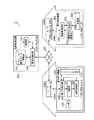
図6は、通信システム2の機能的の構成を示す機能ブロック図である。サーバ101と、WAN105と、ルータ104aと、LAN106aと、要求発行機器102と、ルータ104bと、要求受諾機器301と、LAN106bとを備える。 FIG. 6 is a functional block diagram showing a functional configuration of the communication system 2. The
サーバ101は、要求発行機器102と要求受諾機器301とをピアツーピア接続させるための装置であり、要求発行機器102と、104a及びWAN105を介して接続することができ、要求受諾機器301と、104b及びWAN105を介して接続することができる。 The
要求発行機器102は、要求受諾機器301に対して接続を要求する機器であり、ルータ104a及びWAN105を介してサーバ101と接続される。 The
図6に示すサーバ101及び要求発行機器102は、図2に示した通信システム1におけるサーバ101及び要求発行機器102と同じ処理部をそれぞれ有している。 The
要求受諾機器301は、要求受諾機器103と同様に、本発明の応答機器の一例であり、要求発行機器102からの接続要求に対応する機器である。要求受諾機器103が有する機能に加え、要求発行機器102との接続を認証するための機能を有している。要求受諾機器301は、ルータ104b及びWAN105を介してサーバ101と接続される。 Similar to the
要求受諾機器301は、図2に示した通信システム1における要求受諾機器103と同様に、受諾側通信部130と、機器ID保管部132とを備え、更に、認証部303と、認証パスワード保管部302とを備える。 Similar to the
認証パスワード保管部302は、接続を要求する要求発行機器102に対し、その接続を認証するための認証パスワードを保管する記憶装置である。認証パスワードは本発明の応答機器における第2のパスワードの一例である。 The authentication
認証部303は、要求発行機器102から送信された認証パスワードと、認証パスワード保管部302に保管されている認証パスワードとを比較し、要求発行機器102との接続を認証する処理部である。 The
図6に示すように、通信システム2を構成する各機器には、グローバルIPアドレスまたはプライベートIPアドレスを有しており、サーバ101はグローバルIPアドレスである“230.74.23.6”を、要求発行機器102はプライベートIPアドレスである“192.168.1.11”を、要求受諾機器301はプライベートIPアドレスである“192.168.1.3”を、ルータ104aはグローバルIPアドレスである“4.17.206.2”を、ルータ104bはグローバルIPアドレスである“202.204.16.255”をそれぞれ有していると想定する。 As shown in FIG. 6, each device constituting the communication system 2 has a global IP address or a private IP address, and the
なお、実施の形態2における通信システム2も、通信システム1と同様に、例えば、動画データを再生する動画蓄積機器と動画データを蓄積する動画再生機器とがピアツーピア通信を行ない、動画再生機器に動画データを動画蓄積機器から直接取得させるための動画配信システム等に適用できる。 In the communication system 2 according to the second embodiment, as with the
次に、以上のように構成された通信システム2の動作を図4、図5及び図7を用いて説明する。 Next, the operation of the communication system 2 configured as described above will be described with reference to FIGS. 4, 5, and 7.
図7は、通信システム2における各機器間での通信シーケンスの一例を示す図である。なお、要求受諾機器301は、機器ID保管部132に機器ID“2133”を保管しているものとする。また、図中の「○」は、ルータ104a又はルータ104bにおいて、NAPT機能により、パケットに対するIPアドレス及びポート番号の変換が行われていることを示す。 FIG. 7 is a diagram illustrating an example of a communication sequence between devices in the communication system 2. It is assumed that the
要求受諾機器301は、あらかじめ機器ID“2133”を含む機器登録パケットを、要求側通信部120からサーバ101にUDPを用いて送信する(S201)。 The
機器登録パケットはUDPパケットであるため、要求受諾機器301から送信された時点では、付加情報(UDPヘッダ)として要求受諾機器301のプライベートIPアドレスとポート番号が付加されているが、ルータ104bを通過する際にNAPT機能によって、プライベートIPアドレスとポート番号とが、ルータ104bが有するグローバルIPアドレスと、ルータ104bがサーバ101と通信を行うポート番号とに変換される。 Since the device registration packet is a UDP packet, the private IP address and port number of the
要求受諾機器301は上記機器登録パケットを周期的もしくは必要に応じてサーバ101へ送信する。 The
サーバ101では、サーバ側通信部110が機器登録パケットを受信し、機器登録パケットに含まれる要求受諾機器301の機器ID、及び要求受諾機器301が接続されるルータ104bのグローバルIPアドレスとポート番号との組を対応づけ、図4に示す機器IDリストとして、機器IDリスト保管部111に保管する(S202)。 In the
要求受諾機器301は、周期的もしくは必要に応じて機器登録パケットをサーバ101に送信するため、ルータ104bのWAN側IPアドレスもしくはWAN側ポート番号が変更になった場合でも、自動的に更新される。 Since the
つまり、サーバ101は機器IDリスト保管部111に保管されている機器IDリストを参照することにより、任意のタイミングでサーバ101から要求受諾機器301へパケットを送信することができる。 That is, the
要求発行機器102が要求受諾機器301との通信を行う場合、要求側通信部120は、パスワード生成部121で生成された乱数である使い捨てパスワードと、ユーザによって入力部122から入力された要求受諾機器301の機器ID“2133”、及び要求発行機器102との接続を要求受諾機器301に認証させるためのパスワードである認証パスワードとを取得する。 When the
要求側通信部120は、機器ID及び認証パスワードの取得後、まずサーバ101へのTCP接続を行い(S203)、接続要求パケットCをサーバ101に送信する(S401)。接続要求パケットCには、要求受諾機器301の機器IDと認証パスワード、要求受諾機器301との通信に用いるグローバルIPアドレスとポート番号、及び使い捨てパスワードが含まれている。 After obtaining the device ID and the authentication password, the request
ここで、接続要求パケットCに含まれる、グローバルIPアドレス及びポート番号は、それぞれルータ104aのWAN側IPアドレス及びWAN側ポート番号であり、つまり、要求受諾機器301が要求発行機器102へ直接接続するためのグローバルIPアドレス及びポート番号である。 Here, the global IP address and the port number included in the connection request packet C are the WAN side IP address and the WAN side port number of the
接続要求パケットCをサーバ101へ送信した後のルータ104aが有するNAPTテーブルは、図5に示したNAPTテーブルと同様であり、図5に示すNAPTテーブルの1行目の変換情報は要求発行機器102が送信した接続要求パケットCがルータ104aを通過する際にルータ104aにより決定され、WANルータアドレスとWANルータポートとが、接続要求パケットCの付加情報(TCPヘッダ)として付加される。 The NAPT table of the
また、要求発行機器102が要求受諾機器301からのTCP接続を受け付けるための変換情報は、図5に示すNAPTテーブルの2行目であり、WANルータアドレス“4.17.206.2”と、WANルータポート“5000”とが接続要求パケットCのペイロードに含まれている。これらWANルータアドレス及びWANルータポートの値は、接続要求パケットCの送信前に、要求側通信部120がルータ104aから取得し、接続要求パケットCに含ませる。 Also, the conversion information for the
上記のグローバルIPアドレス“4.17.206.2”、ポート番号“5000”に対してTCP接続がなされた場合、それらグローバルIPアドレス及びポート番号がそれぞれ、ルータ104aのNAPT機能により図5のNAPTテーブルの2行目に示すLAN機器アドレス“192.168.1.11”及びLANルータポート“1600”に変換され、要求発行機器102に対してTCP接続を行うことができる。 When the TCP connection is made to the global IP address “4.17.2020.2” and the port number “5000”, the global IP address and the port number are assigned to the NAPT in FIG. 5 by the NAPT function of the
サーバ101では、サーバ側通信部110が接続要求パケットCを受信し、検索部112が、接続要求パケットCに含まれている接続要求先の機器ID“2133”により、機器IDリスト保管部111に保管されている図4に示す機器IDリストを検索する(S205)。 In the
検索部112は、機器ID“2133”に関連づけられているIPアドレス“202.204.16.255”とポート番号“3400”とを機器IDリストから抽出し、サーバ側通信部110が、それらIPアドレス“202.204.16.255”、とポート番号“3400”とを宛先として、接続要求通知パケットをUDPを用いて送信する(S206)。つまり、接続要求通知パケットが要求受諾機器301へ送信される。接続要求通知パケットは接続要求があったことを要求受諾機器301に通知するためのパケットである。 The
接続要求通知パケットは、機器登録パケットに対する応答としてルータ104bに送信されるため、ルータ104bでIPアドレスとポート番号の変換が行われ、要求受諾機器301に到達できる。 Since the connection request notification packet is transmitted to the
要求受諾機器301は、接続要求通知パケットを受け取ると、受諾側通信部130がサーバ101に対してTCP接続を行う(S207)。 When the
サーバ101は、要求受諾機器301からのTCP接続を受諾すると、TCP接続を介して接続要求パケットDを要求受諾機器301に送信する。接続要求パケットDには、サーバ101が要求発行機器102から受信した接続要求パケットCに含まれている、要求受諾機器301が要求発行機器102との接続を認証するための認証パスワード、要求発行機器102が要求受諾機器301と通信を行うためのグローバルIPアドレス“4.17.206.2”とポート番号“5000”の組、及び使い捨てパスワードが含まれている。 When the
要求受諾機器301では、受諾側通信部130が接続要求パケットDを受信する。認証部303は、接続要求パケットDに含まれている認証パスワードと、認証パスワード保管部302に保有しているパスワードとが一致しているかどうかを確認する。一致している場合、要求発行機器102との接続を許可する(S403)。 In the
認証部303は要求発行機器102との接続を許可する旨を受諾側通信部130に伝える。受諾側通信部130は、要求発行機器102との接続が認証されたことにより、接続要求パケットDに含まれているグローバルIPアドレス“4.17.206.2”とポート番号“5000”に対して、TCP接続を試みると、前述のようにルータ104aのNAPT機能により、要求発行機器102との間でTCP接続を確立することができる(S210)。 The
なお、接続要求パケットDに含まれている認証パスワードと、認証パスワード保管部302に保有しているパスワードが一致しない場合は、認証部303により要求発行機器102との接続が許可されず、受諾側通信部130は要求発行機器102への接続は行わない。 If the authentication password included in the connection request packet D and the password held in the authentication
TCP接続の確立後、受諾側通信部130は、接続要求パケットBに含まれている使い捨てパスワードをそのまま応答パスワードとし、その応答パスワードを含む機器認証パケットを要求発行機器102に送信する(S211)。 After establishing the TCP connection, the accepting
要求発行機器102では、要求側通信部120が機器認証パケットを受信し、判断部123が、受信した機器認証パケットに含まれている応答パスワードと、通信開始にあたって、パスワード生成部121で生成し、接続要求パケットCに含めて送信した使い捨てパスワードとが一致しているかどうかを判断する(S212)。 In the
判断部123により、機器認証パケットに含まれている応答パスワードと、送信前の使い捨てパスワードとが一致していることが判断されると、通信制御部124は、要求側通信部120にそのまま要求受諾機器301との通信を維持させる。以降、要求発行機器102と要求受諾機器301とは、TCP接続210を介して通信を行う(S213)。つまり、要求発行機器102と要求受諾機器301とはピアツーピア通信を行ことができ、例えば動画データ等の大容量のデータであっても、サーバ101に負荷を掛けることなく送受信することができる。 When the
なお、機器認証パケットに含まれている使い捨てパスワードと、送信前の使い捨てパスワードとが一致しないと判断部123が判断した場合、通信制御部124は、要求側通信部120に対し通信の切断を行わせる。 When the
上述のように、要求発行機器102は、要求受諾機器301との通信を行う際、最初にサーバ101に対して接続要求パケットCを送信すると、その接続要求パケットCに含まれる、要求発行機器102と要求受諾機器301との通信に必要な情報が、接続要求パケットDとして要求受諾機器301へ送信される。 As described above, when the
接続要求パケットDには、要求受諾機器301が要求発行機器102との接続を認証するための認証パスワードが含まれており、正しい認証パスワードであれば、要求受諾機器301は要求発行機器102へ接続を行う。つまり、接続の要求元の正当性を確認した上で接続を開始することになる。 The connection request packet D includes an authentication password for the
その後、要求発行機器102は要求受諾機器301から直接接続され、要求受諾機器301とのピアツーピア通信の開始が可能となる。 Thereafter, the
また、要求発行機器102は、接続要求パケットCに使い捨てパスワード含ませて送信し、要求受諾機器301はサーバ101を介し受け取った使い捨てパスワードそのものを応答パスワードとして要求発行機器102に送信する。要求発行機器102は、要求受諾機器301から受信した応答パスワードと、接続要求パケットCに含ませて送信した使い捨てパスワードが一致しているか否かの判断を行う。 The
受信した応答パスワードと送信した使い捨てパスワードとが一致している場合は、機器認証パケットの送信元の機器は、要求発行機器102が接続相手として指定した要求受諾機器103であると判断できる。よって接続相手が正しい機器であることを確認した上で、要求受諾機器103とのピアツーピア通信を維持することができる。 If the received response password matches the transmitted disposable password, it can be determined that the transmission source device of the device authentication packet is the
以上のようにして、グローバルIPアドレスを持たない要求発行機器102が、自身が接続されるLANとは異なったLAN上にある、グローバルIPアドレスを持たない要求受諾機器301との間で、WANを介してピアツーピア通信を行うことができる。また、使い捨てパスワードを用い要求発行機器102が、通信相手が要求受諾機器301である、つまり接続相手が正しい機器であることを確認した上で、ピアツーピア接続の維持を決定するために、要求発行機器102に対する不正なアクセスを防ぐことがでる。 As described above, the
よって、互いに異なるLANに接続される要求発行機器102と要求受諾機器301との間で、安全なピアツーピア通信を行うことがが可能となる。 Therefore, secure peer-to-peer communication can be performed between the
更に、本実施の形態2における通信システム2においては、要求受諾機器301が、要求発行機器102から送信される認証パスワードにより、要求発行機器102との接続の認証を行うため、要求受諾機器301に対する不正なアクセスを防ぐことができ、ピアツーピア通信における安全性が更に向上する。 Furthermore, in the communication system 2 according to the second embodiment, the
なお、上述の実施の形態2において、要求発行機器102がグローバルIPアドレスを有し、直接WAN105に接続されている場合、又は、要求受諾機器301がグローバルIPアドレスを有し、直接WAN105に接続されている場合であっても、要求発行機器102と要求受諾機器301とがピアツーピア通信を行うことが可能である。 In the second embodiment, when the
いずれの場合であっても、ルータ104aまたはルータ104bを介さずに通信を行うだけであり、つまり、ルータによってIPアドレスやポート番号の変換が行われないだけである。その他の、各機器の動作は、上述の実施の形態2の説明で述べた動作と同様である。こうすることで、通信システム2の設計における自由度が向上する。 In any case, the communication is performed without going through the
また、ルータ104aやルータ104bが、NAPT機能ではなくNAT機能のみ有している場合でも同様の動作で要求発行機器102と要求受諾機器301との間で通信を行うことができる。この場合、ルータでポート番号の変換は行われない。こうすることでルータの選択の際の自由度が向上する。 Further, even when the
また、要求発行機器102は、要求受諾機器301から要求発行機器102へのTCP接続(S210)用のIPアドレスとポート番号の組み合わせを常にルータ104aのNAPTテーブル(図5参照)に設定したままでもよいし、要求発行機器102からサーバ101へTCP接続を行う(S203)際にこの組み合わせをNAPTテーブルに設定し、TCP接続が終了するとこの組み合わせをNAPTテーブルから削除するようにしてもよい。NAPTテーブルの設定は、静的NAPTを用いてもよいし、Universal Plug and Playなどの機能を用いてもよい。こうすることで、ルータ104aに対する設定方法をユーザの好みや都合で決定することができる。 Further, the
また、要求発行機器102からサーバ101へのTCP接続(S203)を介した通信、及び要求受諾機器301からサーバ101へのTCP接続(S207)を介した通信は、SSL(Secure Sockets Layer)などの暗号化通信を用いてもよい。この場合、例えば、サーバ101がサーバ証明書を持ち、サーバ101、要求発行機器102、及び要求受諾機器301は、それぞれサーバ証明書を利用した暗号化通信を行うための処理部を持てばよい。こうすることで、要求発行機器102とサーバ101との間の通信、及び、サーバ101と要求受諾機器301との間の通信の秘匿性が高度に保たれる。 Further, communication via the TCP connection (S203) from the
また、要求発行機器102と要求受諾機器301とのピアツーピア通信(S213)はSSLなどの暗号化通信を用いてもよいし、UDPなど他の伝送プロトコルを用いてもよい。こうすることで、要求発行機器102と要求受諾機器301との間で行うピアツーピア通信における通信プロトコルをユーザが自由に選択することができる。 The peer-to-peer communication (S213) between the
また、図6及び図7に図示されたIPアドレス、ポート番号及び機器IDは一例であって、他の値であってもよい。 Further, the IP address, the port number, and the device ID illustrated in FIGS. 6 and 7 are examples, and may be other values.
また、要求発行機器102のパスワード生成部121は、乱数の代わりに疑似乱数を生成し、使い捨てパスワードとして使用してもよい。更に、パスワード生成部121が生成するパスワードは、使い捨てパスワードではなく定常的なパスワードでもよく、要求受諾機器301から送信される応答パスワードとの関係から、接続相手が要求受諾機器301であることを判断できるものであればよい。 Further, the
また、要求発行機器102は、送信した使い捨てパスワードと受信した応答パスワードとが一致すると判断部123が判断した場合に、接続相手が要求受諾機器301であると判断するとしたが、一致ではなく、送信した使い捨てパスワードと受信した応答パスワードとが所定の関連性を有すると判断部123が判断した場合に、接続相手が要求受諾機器301であると判断してもよい。 Further, the
例えば、要求受諾機器301の受諾側通信部130が、使い捨てパスワードに所定の演算を施し、その演算結果である応答パスワードと、送信した使い捨てパスワードとを要求判断部123が比較し、受信した応答パスワードが、送信した使い捨てパスワードに上記の所定の演算を施した結果であるか否かで判断してもよい。また、例えば、受信した応答パスワードが、送信した使い捨てパスワードの一部又は全部を含むか否かで判断してもよい。 For example, the accepting
また、要求発行機器102は、入力部122を備えていなくてもよい。例えば、LAN106aに接続された他の機器から、要求側通信部120を介して機器IDと認証パスワードとを受け取ってもよく、また、接続先が要求受諾機器301だけである場合など、機器IDと認証パスワードとを予め記憶しておき、要求発行機器102の起動時に接続するようにしてもよい。 Further, the
また、上述のように、パスワード生成部121が生成するパスワードは定常的なパスワードでもよく、つまり、接続の度に変更する必要がない場合は、パスワード生成部121を備える必要はない。この場合、例えば、所定のパスワードを所定の領域に記憶しておき、その所定のパスワードを接続要求パケットCに含ませてサーバ101へ送信すればよい。 Further, as described above, the password generated by the
また、要求受諾機器301が要求発行機器102との接続を認証する際、認証部303が、要求発行機器102から送信された認証パスワードと、認証パスワード保管部302に保管された認証パスワードとが一致した場合に、要求発行機器102からの接続を認証するとした。しかしながら、一致ではなく、要求発行機器102から送信された認証パスワードと、認証パスワード保管部302に保管された認証パスワードとが所定の関連性を有する場合に、要求発行機器102からの接続を認証するとしてもよい。 Further, when the
例えば、要求発行機器102から送信された認証パスワードに、認証パスワード保管部302に保管された認証パスワードが含まれる場合に、要求発行機器102からの接続を認証するとしてもよい。 For example, the connection from the
また、サーバ101が機器IDリスト保管部111を備えていなくてもよく、例えば、機器IDなど、要求受諾機器301を識別し、要求受諾機器301へ接続するための情報が記憶された記憶装置を別途接続し、その情報を利用して、要求発行機器102から送信された接続要求パケットDを要求受諾機器301へ送信してもよい。 Further, the
また、要求受諾機器301は機器ID保管部132を備えていなくてもよく、例えば、要求受諾機器301がLAN106b内で割り当てられるプライベートIPアドレスが一定である場合は要求受諾機器301を識別する識別子としてそのプライベートIPアドレスを用いればよい。 Further, the
この場合、例えば、要求発行機器102は、接続先としてそのプライベートIPアドレスを接続要求パケットCに含ませてサーバ101へ送信すればよい。また、サーバ101は、そのプライベートIPアドレスと、LAN106aのグローバルIPアドレスと、要求受諾機器301とサーバ101とが通信するためのポート番号とを対応付けた情報を記憶しておく、又は、外部の記憶装置等から取り込み利用すればよい。 In this case, for example, the
上述のように、要求発行機器102、サーバ101又は要求受諾機器301を構成する処理部や、その処理方法に自由度を持たせることで、通信システム2の構築の際に、ハードウェア/ソフトウェアの選択・設計に自由度を持たせることができる。 As described above, when the communication system 2 is constructed, the processing units and the processing methods constituting the
本発明は、要求を中継するサーバを利用することで、互いに異なったLAN上にある、グローバルIPアドレスを持たない機器同士でピアツーピア通信を行う通信システムに利用でき、特に、動画データ等の容量の大きなデータを送受信する通信システムとして有用である。 The present invention can be used in a communication system that performs peer-to-peer communication between devices that do not have a global IP address on different LANs by using a server that relays a request. It is useful as a communication system for transmitting and receiving large data.
1、2 通信システム
101 サーバ
102 要求発行機器
103、301 要求受諾機器
104a、104b ルータ
105 WAN
106a、106b LAN
110 サーバ側通信部
111 機器IDリスト保管部
112 検索部
120 要求側通信部
121 パスワード生成部
122 入力部
123 判断部
124 通信制御部
130 受諾側通信部
132 機器ID保管部
302 認証パスワード保管部
303 認証部
1, 2
106a, 106b LAN
DESCRIPTION OF
Claims (26)
Translated fromJapanese前記接続要求機器は、前記応答機器の識別子と、前記第1のネットワークのグローバルIPアドレスと、前記応答機器との通信に用いるポート番号と、前記応答機器との通信の確立を確認するための第1のパスワードとを前記接続管理装置に送信し、
前記接続管理装置は、前記識別子と前記グローバルIPアドレスと前記ポート番号と前記第1のパスワードとを前記接続要求機器から受信し、前記グローバルIPアドレスと前記ポート番号と前記第1のパスワードとを、前記識別子を利用して前記応答機器へ送信し、
前記応答機器は、前記グローバルIPアドレスと前記ポート番号と前記第1のパスワードとを前記接続管理装置から受信し、前記第1のパスワードと関連する応答パスワードを、前記グローバルIPアドレスと前記ポート番号とを利用して前記接続要求機器へ送信し、
前記接続要求機器は、更に、前記グローバルIPアドレスと前記ポート番号とが利用されて前記応答機器から送信された前記応答パスワードを受信し、
(1)受信された前記応答パスワードと前記第1のパスワードとが関連すると判断した場合、前記応答機器との接続を維持し、
(2)受信された前記応答パスワードと前記第1のパスワードとが関連しないと判断した場合、前記応答機器との接続を切断する
通信システム。Connection request connected to the first network, response device connected to the second network, and connection management connected to the third network connecting the first network and the second network A communication system comprising a device,
The connection requesting device confirms the establishment of communication with the response device, the identifier of the response device, the global IP address of the first network, the port number used for communication with the response device. 1 password to the connection management device,
The connection management device receives the identifier, the global IP address, the port number, and the first password from the connection requesting device, and receives the global IP address, the port number, and the first password. Sending to the response device using the identifier,
The response device receives the global IP address, the port number, and the first password from the connection management device, and transmits a response password associated with the first password to the global IP address and the port number. To the connection request device using
The connection requesting device further receives the response password transmitted from the response device using the global IP address and the port number,
(1) If it is determined that the received response password and the first password are related, maintaining a connection with the response device;
(2) A communication system that disconnects the response device when it is determined that the received response password is not related to the first password.
前記応答機器の識別子と、前記第1のネットワークのグローバルIPアドレスと、前記接続要求機器が前記応答機器との通信に用いるポート番号と、前記応答機器との通信の確立を確認するための第1のパスワードとを、前記第1のネットワークと前記第2のネットワークとを接続する第3のネットワークに接続される接続管理装置へ送信する第1送信手段と、
前記グローバルIPアドレスと前記ポート番号とが利用されて前記応答機器から送信される応答パスワードを受信する第1受信手段と、
前記第1送信手段が送信した前記第1のパスワードと前記第1受信手段が受信した前記応答パスワードとが関連するか否かを判断する判断手段と、
前記判断手段が、(1)前記応答パスワードと前記第1のパスワードとが関連すると判断した場合、前記応答機器との接続を前記第1送信手段及び前記第1受信手段に維持させ、(2)前記応答パスワードと前記第1のパスワードとが関連しないと判断した場合、前記応答機器との接続を前記第1送信手段及び前記第1受信手段に切断させる通信制御手段と
を備える接続要求機器。A connection requesting device connected to the first network and requesting connection to a response device connected to the second network;
An identifier of the response device, a global IP address of the first network, a port number used by the connection request device for communication with the response device, and a first for confirming establishment of communication with the response device A first transmission means for transmitting the password to a connection management device connected to a third network connecting the first network and the second network;
First receiving means for receiving a response password transmitted from the response device using the global IP address and the port number;
Determining means for determining whether or not the first password transmitted by the first transmitting means and the response password received by the first receiving means are related;
If the determination means determines that (1) the response password and the first password are related, the connection to the response device is maintained by the first transmission means and the first reception means, and (2) A connection request device comprising: a communication control unit that causes the first transmission unit and the first reception unit to disconnect the response device when it is determined that the response password and the first password are not related.
前記パスワード生成手段は、前記応答機器との通信において、一回の前記通信にのみ有効な使い捨てパスワードを生成し、
前記第1送信手段は、前記使い捨てパスワードを前記第1のパスワードとして前記接続管理装置に送信する
請求項2記載の接続要求機器。Furthermore, it comprises password generating means for generating the first password,
The password generation means generates a disposable password that is valid for only one communication in communication with the response device,
The connection request device according to claim 2, wherein the first transmission unit transmits the disposable password to the connection management device as the first password.
請求項3記載の接続要求機器。The connection request device according to claim 3, wherein the password generation unit generates a random number or a pseudo-random number as the disposable password.
請求項2記載の接続要求機器。The connection requesting device according to claim 2, wherein the determination unit determines that the first password and the response password are related when the first password matches the response password.
前記第1送信手段は前記入力手段により入力された前記識別子を前記接続管理装置に送信する
請求項2記載の接続要求機器。Furthermore, an input means for the user to input the identifier is provided,
The connection requesting device according to claim 2, wherein the first transmission unit transmits the identifier input by the input unit to the connection management device.
前記第1送信手段は、前記暗号手段により暗号化された前記情報を前記接続管理装置に送信する
請求項2記載の接続要求機器。And further comprising encryption means for encrypting information transmitted by the first transmission means,
The connection request device according to claim 2, wherein the first transmission unit transmits the information encrypted by the encryption unit to the connection management device.
請求項2記載の接続要求機器。The connection request device according to claim 2, wherein the first transmission unit further transmits a second password for allowing the response device to authenticate connection with the connection request device to the connection management device.
前記第1送信手段は前記入力手段により入力された前記第2のパスワードを前記接続管理装置に送信する
請求項8記載の接続要求機器。Furthermore, an input means for the user to input the second password is provided,
The connection request device according to claim 8, wherein the first transmission unit transmits the second password input by the input unit to the connection management apparatus.
前記応答機器の識別子である要求先識別子と、前記第1のネットワークのグローバルIPアドレスと、前記接続要求機器が前記応答機器との通信に用いる第1のポート番号と、前記接続要求機器が前記応答機器との通信の確立を確認するための第1のパスワードとを前記接続要求機器から受信する第3受信手段と、
前記グローバルIPアドレスと前記第1のポート番号と前記第1のパスワードとを前記要求先識別子を利用して前記応答機器に送信する第3送信手段と
を備える接続管理装置。A connection management device connected to a third network for connecting a first network to which a connection requesting device is connected and a second network to which a response device is connected;
A request destination identifier which is an identifier of the response device, a global IP address of the first network, a first port number used by the connection requesting device for communication with the response device, and the connection requesting device responding to the response Third receiving means for receiving from the connection requesting device a first password for confirming establishment of communication with the device;
A connection management device comprising: third transmission means for transmitting the global IP address, the first port number, and the first password to the response device using the request destination identifier.
前記応答機器の前記アドレスを前記記憶手段に記憶された情報から検索する検索手段とを備え、
前記第3受信手段は、更に、前記応答機器から、前記応答機器の識別子である機器識別子と、前記第2のネットワークのグローバルIPアドレスと、前記応答機器が前記接続管理装置との通信に用いる第2のポート番号とを受信し、
前記記憶手段は、前記第3受信手段が受信した前記機器識別子と前記第2のネットワークのグローバルIPアドレスと前記第2のポート番号とを対応付けて前記アドレスを特定する情報として記憶し、
前記検索手段は、前記接続要求機器から受信した前記要求先識別子と前記記憶手段に記憶されている前記機器識別子とを比較対照し、前記第2のネットワークのグローバルIPアドレスと前記第2のポート番号とを検索し、
前記第3送信手段は、前記第1のネットワークのグローバルIPアドレスと前記第1のポート番号と前記第1のパスワードとを、前記検索手段によって検索された前記第2のネットワークのグローバルIPアドレスと前記第2のポート番号とを利用して前記応答機器へ送信する
請求項10記載の接続管理装置。Storage means for storing information identifying the address of the responding device;
Search means for searching for the address of the response device from information stored in the storage means,
The third receiving means further receives, from the responding device, a device identifier that is an identifier of the responding device, a global IP address of the second network, and a second that the responding device uses for communication with the connection management device. 2 port number,
The storage means stores the device identifier received by the third receiving means, the global IP address of the second network, and the second port number as information for identifying the address,
The search unit compares and contrasts the request destination identifier received from the connection requesting device with the device identifier stored in the storage unit, and determines the global IP address and the second port number of the second network. And search for
The third transmission means includes the global IP address of the first network, the first port number, and the first password, the global IP address of the second network searched by the search means, and the The connection management apparatus according to claim 10, wherein the connection management apparatus transmits to the response device using a second port number.
前記第3送信手段は、前記第2のパスワードを前記応答機器へ送信する
請求項10記載の接続管理装置。The third receiving means further receives, from the connection requesting device, a second password for causing the responding device to authenticate connection with the connection requesting device,
The connection management apparatus according to claim 10, wherein the third transmission unit transmits the second password to the response device.
前記第3受信手段は、前記応答機器から前記通知パケットの応答を受信し、
前記第3送信手段は、前記受信手段が前記応答を受信すると前記第1のネットワークのグローバルIPアドレスと前記第1のポート番号と前記第1のパスワードとを前記応答機器へ送信する
請求項10記載の接続管理装置。The third transmission means transmits a notification packet for notifying transmission of information to the response device to the response device using a UDP protocol,
The third receiving means receives the response of the notification packet from the response device,
The said 3rd transmission means transmits the global IP address of the said 1st network, the said 1st port number, and the said 1st password to the said response apparatus, when the said reception means receives the said response. Connection management device.
前記第3受信手段は、前記接続要求機器から暗号化された情報を受信し、
前記暗号手段は、暗号化された前記情報を復号化し、復号化された前記情報に含まれる前記第1のネットワークのグローバルIPアドレスと前記第1のポート番号と前記第1のパスワードとを暗号化し、
前記第3送信手段は、前記暗号化された前記第1のネットワークのグローバルIPアドレスと前記第1のポート番号と前記第1のパスワードとを前記応答機器へ送信する
請求項10記載の接続管理装置。Furthermore, an encryption means for encrypting and decrypting communication contents is provided,
The third receiving means receives encrypted information from the connection requesting device;
The encryption means decrypts the encrypted information, and encrypts the global IP address of the first network, the first port number, and the first password included in the decrypted information. ,
The connection management device according to claim 10, wherein the third transmission unit transmits the encrypted global IP address of the first network, the first port number, and the first password to the response device. .
前記第1のネットワークのグローバルIPアドレスと、前記接続要求機器が前記応答機器との通信に用いる第1のポート番号と、前記接続要求機器が前記応答機器との通信の確立を確認するための第1のパスワードとを、前記第1のネットワークと前記第2のネットワークとを接続する第3のネットワークに接続される接続管理装置から受信する第2受信手段と、
前記第1のパスワードと関連する応答パスワードを、前記グローバルIPアドレスと前記第1のポート番号とを利用して前記接続要求機器へ送信する第2送信手段と
を備える応答機器。A response device connected to the second network and responding to a connection request from a connection request device connected to the first network;
A global IP address of the first network, a first port number used by the connection requesting device for communication with the response device, and a first for confirming establishment of communication with the response device by the connection requesting device. Second receiving means for receiving one password from a connection management device connected to a third network that connects the first network and the second network;
A response device comprising: a second transmission unit configured to transmit a response password associated with the first password to the connection requesting device using the global IP address and the first port number.
請求項15記載の応答機器。The second transmission means transmits the first password as a response password to the connection requesting device.
The response device according to claim 15.
前記第2送信手段は、更に、前記識別子記憶手段に記憶されている前記識別子と、前記第2のネットワークのグローバルIPアドレスと、前記応答機器が前記接続管理装置との通信に用いる第2のポート番号とを前記接続管理装置に登録するために、前記識別子を前記管理装置に送信する
請求項15記載の応答機器。Comprising identifier storage means for storing an identifier of the response device;
The second transmission means further includes the identifier stored in the identifier storage means, the global IP address of the second network, and a second port used by the responding device for communication with the connection management device. The response device according to claim 15, wherein the identifier is transmitted to the management device in order to register a number with the connection management device.
前記接続要求機器との接続の可否を認証する認証手段とを備え、
前記第2受信手段は、前記接続管理装置から接続の認証を要求する認証要求パスワードを受信し、
前記認証部は、前記認証要求パスワードと前記パスワード記憶手段に記憶された第2のパスワードとが関連すると判断した場合に、前記接続要求機器との接続を許可し、
前記第2送信手段は、前記認証部により前記接続要求機器との接続が許可された場合、前記応答パスワードを前記接続要求機器へ送信する
請求項15記載の応答機器。And password storage means for storing a second password for authenticating whether or not the connection requesting device can be connected;
Authentication means for authenticating whether or not connection with the connection requesting device is possible,
The second receiving means receives an authentication request password for requesting connection authentication from the connection management device;
When the authentication unit determines that the authentication request password and the second password stored in the password storage unit are related, the authentication unit permits connection with the connection request device;
The response device according to claim 15, wherein the second transmission unit transmits the response password to the connection requesting device when the authentication unit permits the connection with the connection requesting device.
前記第2送信手段は、前記第2受信手段が受信した前記通知パケットの応答を前記接続管理装置に送信し、
前記第2受信手段は、更に、前記応答に対応して前記接続管理装置から送信される前記第1のネットワークのグローバルIPアドレスと前記第1のポート番号と前記第1のパスワードを受信する
請求項15記載の応答機器。The second receiving means receives a notification packet for notifying transmission of information from the connection management device using a UDP protocol,
The second transmission means transmits a response of the notification packet received by the second reception means to the connection management device,
The second receiving means further receives the global IP address of the first network, the first port number, and the first password transmitted from the connection management device in response to the response. 15. The response device according to 15.
前記第2受信手段は、前記接続管理装置から暗号化された情報を受信し、
前記復号手段は、暗号化された前記情報を復号化し、
前記第2送信手段は、復号化された前記情報に含まれる前記第1のパスワードと関連する応答パスワードを、復号化された前記情報に含まれる前記グローバルIPアドレスと前記第1のポート番号とを利用して前記接続要求機器へ送信する
請求項15記載の応答機器。Furthermore, a decryption means for decrypting the encrypted information is provided,
The second receiving means receives encrypted information from the connection management device;
The decryption means decrypts the encrypted information;
The second transmission means obtains a response password associated with the first password included in the decrypted information, and the global IP address and the first port number included in the decrypted information. The response device according to claim 15, wherein the response device transmits the connection request device to the connection request device.
前記応答機器の識別子と、前記第1のネットワークのグローバルIPアドレスと、前記接続要求機器が前記応答機器との通信に用いるポート番号と、前記応答機器との通信の確立を確認するための第1のパスワードとを、前記第1のネットワークと前記第2のネットワークとを接続する第3のネットワークに接続される接続管理装置へ送信する送信ステップと、
前記グローバルIPアドレスと前記ポート番号とが利用されて前記応答機器から送信される応答パスワードを受信する受信ステップと、
前記受信ステップにおいて受信された前記応答パスワードと前記送信ステップにおいて送信された前記第1のパスワードとが関連するか否かを判断する判断ステップと、
前記判断ステップにおいて、(1)前記応答パスワードと前記第1のパスワードとが関連すると判断された場合、前記応答機器との接続を維持させ、(2)前記応答パスワードと前記第1のパスワードとが関連しないと判断した場合、前記応答機器との接続を切断させる通信制御ステップと
を含む通信確立方法。A communication establishment method for establishing communication between a connection request device connected to a first network and a response device connected to a second network,
An identifier of the response device, a global IP address of the first network, a port number used by the connection request device for communication with the response device, and a first for confirming establishment of communication with the response device Transmitting the password to the connection management device connected to the third network connecting the first network and the second network;
Receiving a response password transmitted from the response device using the global IP address and the port number; and
A determination step of determining whether or not the response password received in the reception step is related to the first password transmitted in the transmission step;
In the determination step, (1) when it is determined that the response password and the first password are related, the connection with the response device is maintained, and (2) the response password and the first password are A communication control method comprising: a communication control step of disconnecting the connection with the responding device when it is determined that they are not related.
前記応答機器の識別子である要求先識別子と、前記第1のネットワークのグローバルIPアドレスと、前記接続要求機器が前記応答機器との通信に用いる第1のポート番号と、前記接続要求機器が前記応答機器との通信の確立を確認するための第1のパスワードとを前記接続要求機器から受信する受信ステップと、
前記グローバルIPアドレスと前記第1のポート番号と前記第1のパスワードとを前記要求先識別子を利用して前記応答機器に送信する送信ステップと
を含む通信開始方法。A communication start method for causing a response device connected to a second network to start communication with a connection request device connected to a first network, the request destination identifier being an identifier of the response device, and the first A global IP address of the network, a first port number used by the connection requesting device for communication with the responding device, and a first password for the connection requesting device to confirm establishment of communication with the responding device Receiving from the connection requesting device,
A transmission start method including: a transmission step of transmitting the global IP address, the first port number, and the first password to the response device using the request destination identifier.
前記第1のネットワークのグローバルIPアドレスと、前記接続要求機器が前記応答機器との通信に対応するための第1のポート番号と、前記接続要求機器が前記応答機器との通信の確立を確認するための第1のパスワードとを、前記第1のネットワークと前記第2のネットワークとを接続する第3のネットワークに接続される接続管理装置から受信する受信ステップと、
前記第1のパスワードと関連する応答パスワードを、前記グローバルIPアドレスと前記第1のポート番号とを利用して前記接続要求機器へ送信する送信ステップと
を含む応答方法。A response device connected to a second network is a response method for responding to a request from a connection request device connected to the first network, wherein the global IP address of the first network and the connection request device are A first port number for supporting communication with the response device, a first password for the connection requesting device to confirm establishment of communication with the response device, and the first network and the Receiving from the connection management device connected to the third network for connecting the second network;
A response method including: a transmission step of transmitting a response password associated with the first password to the connection requesting device using the global IP address and the first port number.
前記応答機器の識別子と、前記第1のネットワークのグローバルIPアドレスと、前記接続要求機器が前記応答機器との通信に用いるポート番号と、前記応答機器との通信の確立を確認するための第1のパスワードとを、前記第1のネットワークと前記第2のネットワークとを接続する第3のネットワークに接続される接続管理装置へ送信する送信ステップと、
前記グローバルIPアドレスと前記ポート番号とが利用されて前記応答機器から送信される応答パスワードを受信する受信ステップと、
前記受信ステップにおいて受信された前記応答パスワードと前記送信ステップにおいて送信された前記第1のパスワードとが関連するか否かを判断する判断ステップと、
前記判断ステップにおいて、(1)前記応答パスワードと前記第1のパスワードとが関連すると判断された場合、前記応答機器との接続を維持させ、(2)前記応答パスワードと前記第1のパスワードとが関連しないと判断した場合、前記応答機器との接続を切断させる通信制御ステップと
をコンピュータに実行させるためのプログラム。A connection request device connected to the first network is a program for establishing communication with a response device connected to the second network,
An identifier of the response device, a global IP address of the first network, a port number used by the connection request device for communication with the response device, and a first for confirming establishment of communication with the response device Transmitting the password to the connection management device connected to the third network connecting the first network and the second network;
Receiving a response password transmitted from the response device using the global IP address and the port number; and
A determination step of determining whether or not the response password received in the reception step is related to the first password transmitted in the transmission step;
In the determination step, (1) when it is determined that the response password and the first password are related, the connection with the response device is maintained, and (2) the response password and the first password are A program for causing a computer to execute a communication control step of disconnecting the connection with the responding device when it is determined that they are not related.
前記応答機器の識別子である要求先識別子と、前記第1のネットワークのグローバルIPアドレスと、前記接続要求機器が前記応答機器との通信に用いる第1のポート番号と、前記接続要求機器が前記応答機器との通信の確立を確認するための第1のパスワードとを前記接続要求機器から受信する受信ステップと、
前記グローバルIPアドレスと前記第1のポート番号と前記第1のパスワードとを前記要求先識別子を利用して前記応答機器に送信する送信ステップと
をコンピュータに実行させるためのプログラム。A program for causing a response device connected to the second network to start communication with a connection requesting device connected to the first network,
A request destination identifier which is an identifier of the response device, a global IP address of the first network, a first port number used by the connection requesting device for communication with the response device, and the connection requesting device responding to the response Receiving from the connection requesting device a first password for confirming establishment of communication with the device;
A program for causing a computer to execute a transmission step of transmitting the global IP address, the first port number, and the first password to the response device using the request destination identifier.
前記第1のネットワークのグローバルIPアドレスと、前記接続要求機器が前記応答機器との通信に用いる第1のポート番号と、前記接続要求機器が前記応答機器との通信の確立を確認するための第1のパスワードとを、前記第1のネットワークと前記第2のネットワークとを接続する第3のネットワークに接続される接続管理装置から受信する受信ステップと、
前記第1のパスワードと関連する応答パスワードを、前記グローバルIPアドレスと前記第1のポート番号とを利用して前記接続要求機器へ送信する送信ステップと
をコンピュータに実行させるためのプログラム。
A response device connected to the second network is a program for responding to a request from a connection requesting device connected to the first network,
A global IP address of the first network, a first port number used by the connection requesting device for communication with the response device, and a first for confirming establishment of communication with the response device by the connection requesting device. Receiving a first password from a connection management device connected to a third network connecting the first network and the second network;
A program for causing a computer to execute a transmission step of transmitting a response password associated with the first password to the connection requesting device using the global IP address and the first port number.
Priority Applications (1)
| Application Number | Priority Date | Filing Date | Title |
|---|---|---|---|
| JP2004293902AJP2006109152A (en) | 2004-10-06 | 2004-10-06 | Connection request device, response device, connection management device, and communication system for communication on network |
Applications Claiming Priority (1)
| Application Number | Priority Date | Filing Date | Title |
|---|---|---|---|
| JP2004293902AJP2006109152A (en) | 2004-10-06 | 2004-10-06 | Connection request device, response device, connection management device, and communication system for communication on network |
Publications (1)
| Publication Number | Publication Date |
|---|---|
| JP2006109152Atrue JP2006109152A (en) | 2006-04-20 |
Family
ID=36378339
Family Applications (1)
| Application Number | Title | Priority Date | Filing Date |
|---|---|---|---|
| JP2004293902APendingJP2006109152A (en) | 2004-10-06 | 2004-10-06 | Connection request device, response device, connection management device, and communication system for communication on network |
Country Status (1)
| Country | Link |
|---|---|
| JP (1) | JP2006109152A (en) |
Cited By (10)
| Publication number | Priority date | Publication date | Assignee | Title |
|---|---|---|---|---|
| JP2009151479A (en)* | 2007-12-19 | 2009-07-09 | Sony Corp | Network system, direct access method, network household electrical appliance, and program |
| JP2009251648A (en)* | 2008-04-01 | 2009-10-29 | Sony Corp | Server device, network system, data transfer method and program |
| JP2012109996A (en)* | 2006-11-03 | 2012-06-07 | Alcatel-Lucent Usa Inc | Methods and apparatus for delivering control messages during malicious attack in one or more packet networks |
| JP2013243674A (en)* | 2012-05-21 | 2013-12-05 | Rsupport Co Ltd | Method for connection between terminals |
| JP2014150461A (en)* | 2013-02-01 | 2014-08-21 | Nec Access Technica Ltd | Communication system and communication method |
| WO2014133300A1 (en)* | 2013-02-26 | 2014-09-04 | (주)이스톰 | Otp authentication system and method |
| KR101513694B1 (en) | 2013-02-26 | 2015-04-22 | (주)이스톰 | System and Method for OTP authentication |
| JP2016134715A (en)* | 2015-01-19 | 2016-07-25 | エヌ・ティ・ティ・コミュニケーションズ株式会社 | Terminal management system, terminal control device, terminal management method, and communication control program |
| CN110391933A (en)* | 2019-06-17 | 2019-10-29 | 浙江工商大学 | A kind of embedded device parameter configuration recovery method and embedded device |
| JP2019533250A (en)* | 2016-10-11 | 2019-11-14 | シエン ヴァン ファムPHAM, Thien, Van | Method, system, and medium for pairing devices and completing tasks using application requests |
- 2004
- 2004-10-06JPJP2004293902Apatent/JP2006109152A/enactivePending
Cited By (13)
| Publication number | Priority date | Publication date | Assignee | Title |
|---|---|---|---|---|
| JP2012109996A (en)* | 2006-11-03 | 2012-06-07 | Alcatel-Lucent Usa Inc | Methods and apparatus for delivering control messages during malicious attack in one or more packet networks |
| JP2009151479A (en)* | 2007-12-19 | 2009-07-09 | Sony Corp | Network system, direct access method, network household electrical appliance, and program |
| US8230488B2 (en) | 2007-12-19 | 2012-07-24 | Sony Corporation | Network system, direct-access method, network household electrical appliance, and program |
| JP2009251648A (en)* | 2008-04-01 | 2009-10-29 | Sony Corp | Server device, network system, data transfer method and program |
| US8301691B2 (en) | 2008-04-01 | 2012-10-30 | Sony Corporation | Server apparatus, network system, data transfer method, and program |
| JP2013243674A (en)* | 2012-05-21 | 2013-12-05 | Rsupport Co Ltd | Method for connection between terminals |
| JP2014150461A (en)* | 2013-02-01 | 2014-08-21 | Nec Access Technica Ltd | Communication system and communication method |
| WO2014133300A1 (en)* | 2013-02-26 | 2014-09-04 | (주)이스톰 | Otp authentication system and method |
| KR101513694B1 (en) | 2013-02-26 | 2015-04-22 | (주)이스톰 | System and Method for OTP authentication |
| US10003595B2 (en) | 2013-02-26 | 2018-06-19 | eStorm Co., LTD | System and method for one time password authentication |
| JP2016134715A (en)* | 2015-01-19 | 2016-07-25 | エヌ・ティ・ティ・コミュニケーションズ株式会社 | Terminal management system, terminal control device, terminal management method, and communication control program |
| JP2019533250A (en)* | 2016-10-11 | 2019-11-14 | シエン ヴァン ファムPHAM, Thien, Van | Method, system, and medium for pairing devices and completing tasks using application requests |
| CN110391933A (en)* | 2019-06-17 | 2019-10-29 | 浙江工商大学 | A kind of embedded device parameter configuration recovery method and embedded device |
Similar Documents
| Publication | Publication Date | Title |
|---|---|---|
| JP4729602B2 (en) | Server device, communication device, communication system, program, and recording medium | |
| US7870261B2 (en) | Information processing device, an information processing method, and a computer program to securely connect clients on an external network to devices within an internal network | |
| JP4727126B2 (en) | Providing secure network access for short-range wireless computing devices | |
| JP3912609B2 (en) | Remote access VPN mediation method and mediation device | |
| US8312532B2 (en) | Connection supporting apparatus | |
| KR100803272B1 (en) | Method and apparatus for processing authentication in IP V6 network | |
| US20060168253A1 (en) | Access control processing method | |
| KR20050054970A (en) | Apparatuses, method and computer software products for controlling a home terminal | |
| US20090327730A1 (en) | Apparatus and method for encrypted communication processing | |
| US20080267395A1 (en) | Apparatus and method for encrypted communication processing | |
| JP2006109152A (en) | Connection request device, response device, connection management device, and communication system for communication on network | |
| JP2005236728A (en) | Server device, request issuing device, request accepting device, communication system, and communication method | |
| JP4367002B2 (en) | Network device, network system, and group management method | |
| JP4909026B2 (en) | Receiving apparatus, method, and program | |
| US20160105407A1 (en) | Information processing apparatus, terminal, information processing system, and information processing method | |
| JP4764410B2 (en) | Communication service providing system, address assignment device, and signal processing device | |
| JP4775154B2 (en) | COMMUNICATION SYSTEM, TERMINAL DEVICE, PROGRAM, AND COMMUNICATION METHOD | |
| JP2004072633A (en) | IPv6 node accommodation method and IPv6 node accommodation system | |
| JP2006019824A (en) | Secure communication system, management device, and communication terminal | |
| JP2005303784A (en) | Server device, request issuing device, request accepting device, communication system, communication method, and program | |
| JP2009081710A (en) | COMMUNICATION DEVICE AND COMMUNICATION METHOD USED FOR COMMUNICATION DEVICE | |
| JP2005311747A (en) | Server device, request issuing device, request accepting device, communication system, and program | |
| JP2006197094A (en) | Communications system | |
| KR20070017329A (en) | Secure end-to-end TC / IP communication method by proxy and communication system |