JP2006108881A - Slide mechanism of mobile apparatus and mobile phone - Google Patents
Slide mechanism of mobile apparatus and mobile phoneDownload PDFInfo
- Publication number
- JP2006108881A JP2006108881AJP2004290272AJP2004290272AJP2006108881AJP 2006108881 AJP2006108881 AJP 2006108881AJP 2004290272 AJP2004290272 AJP 2004290272AJP 2004290272 AJP2004290272 AJP 2004290272AJP 2006108881 AJP2006108881 AJP 2006108881A
- Authority
- JP
- Japan
- Prior art keywords
- slider
- base member
- casing
- slide
- slide mechanism
- Prior art date
- Legal status (The legal status is an assumption and is not a legal conclusion. Google has not performed a legal analysis and makes no representation as to the accuracy of the status listed.)
- Pending
Links
- 230000001105regulatory effectEffects0.000description4
- 230000007935neutral effectEffects0.000description3
- 239000002184metalSubstances0.000description2
- 229910001220stainless steelInorganic materials0.000description2
- 239000010935stainless steelSubstances0.000description2
- 229920003002synthetic resinPolymers0.000description2
- 239000000057synthetic resinSubstances0.000description2
- 230000001413cellular effectEffects0.000description1
- 239000000463materialSubstances0.000description1
- 230000000149penetrating effectEffects0.000description1
- 238000003466weldingMethods0.000description1
Images


Classifications
- H—ELECTRICITY
- H04—ELECTRIC COMMUNICATION TECHNIQUE
- H04B—TRANSMISSION
- H04B1/00—Details of transmission systems, not covered by a single one of groups H04B3/00 - H04B13/00; Details of transmission systems not characterised by the medium used for transmission
- H04B1/38—Transceivers, i.e. devices in which transmitter and receiver form a structural unit and in which at least one part is used for functions of transmitting and receiving
- H—ELECTRICITY
- H04—ELECTRIC COMMUNICATION TECHNIQUE
- H04M—TELEPHONIC COMMUNICATION
- H04M1/00—Substation equipment, e.g. for use by subscribers
- H04M1/02—Constructional features of telephone sets
- H04M1/0202—Portable telephone sets, e.g. cordless phones, mobile phones or bar type handsets
- H04M1/0206—Portable telephones comprising a plurality of mechanically joined movable body parts, e.g. hinged housings
- H04M1/0208—Portable telephones comprising a plurality of mechanically joined movable body parts, e.g. hinged housings characterized by the relative motions of the body parts
- H04M1/0235—Slidable or telescopic telephones, i.e. with a relative translation movement of the body parts; Telephones using a combination of translation and other relative motions of the body parts
- H04M1/0237—Sliding mechanism with one degree of freedom
Landscapes
- Engineering & Computer Science (AREA)
- Signal Processing (AREA)
- Computer Networks & Wireless Communication (AREA)
- Telephone Set Structure (AREA)
- Casings For Electric Apparatus (AREA)
Abstract
Description
Translated fromJapanese本発明は、携帯電話機などの携帯機器を構成する第1の筐体と第2の筐体を直線方向に相対的にスライドさせる際に用いられて好適な携帯機器のスライド機構及びその携帯機器のスライド機構を備えた携帯電話機に関するものである。 INDUSTRIAL APPLICABILITY The present invention relates to a slide mechanism for a portable device that is preferably used when the first casing and the second casing constituting the portable device such as a cellular phone are relatively slid in the linear direction, and the portable device. The present invention relates to a mobile phone provided with a slide mechanism.
携帯機器の一種である携帯電話機において、キーボード部やマイク部等を上面に設けた送話部としての第1の筐体と、ディスプレイ部やスピーカー部等を上面に設けた受話部としての第2の筐体とを有し、これらの第1の筐体と第2の筐体が完全に重なり合って第2の筐体で第1の筐体の上面を覆う状態と、第2の筐体を第1の筐体に対して長手方向へスライドさせて第1の筐体の上面を露出させる状態とを作り出す、スライド機構付きのものが市場に出回っている。このようなスライド機構を有する携帯電話機としては、下記する特許文献1に記載されたものが公知である。
この特許文献1に記載されたものは、スライドカバーとロックプレートを重ね合わせて固着したスライドケースを第2の筐体の下面に取り付けると共に、スライドケース内に摺動可能に収装したスライダーを第1の筐体の上面に取り付けることで、第2の筐体を第1の筐体に対してスライドさせることができるという構成のものであった。このような構成であると、第1の筐体と第2の筐体の相対的操作、即ち、スライド操作は全て手動で行わなくてはならず、操作性の点で難点があった。 In this patent document 1, a slide case in which a slide cover and a lock plate are overlapped and fixed is attached to the lower surface of the second housing, and a slider slidably accommodated in the slide case is attached to the first case. The second casing can be slid with respect to the first casing by being attached to the upper surface of the first casing. With such a configuration, all the relative operations of the first casing and the second casing, that is, the slide operation, must be performed manually, which is difficult in terms of operability.
本発明は、前記課題を解決するためになされたものであって、その目的は、半自動でスライド動作を行えるように構成した携帯機器のスライド機構及びその携帯機器のスライド機構を備えた携帯電話機を提供することにある。 The present invention has been made to solve the above-described problems, and an object of the present invention is to provide a slide mechanism of a portable device configured to perform a semi-automatic sliding operation and a mobile phone including the slide mechanism of the portable device. It is to provide.
前記の目的を達成するための本発明に係る携帯機器のスライド機構は、携帯機器を構成する第1の筐体と第2の筐体を互いに重ね合わせた状態で相対的に直線方向へ開閉可能にスライドさせるスライド機構であって、前記第1の筐体と前記第2の筐体のいずれか一方に取り付けられるベース部材と、このベース部材に対しスライド可能に係合され、前記第1の筐体と前記第2の筐体のいずれか他方に取り付けられるスライダーと、このスライダーと前記ベース部材の間に設けられたスライド付勢手段とからなり、このスライド付勢手段を、前記ベース部材と前記スライダーのいずれか一方に回動可能に取り付けられている回動アームと、前記ベース部材と前記スライダーのいずれか他方に取り付けられ、前記回動アームに作用して該回動アームを所定回動位置から左右いずれの方向へも回動付勢させることによって前記第1の筐体と前記第2の筐体を所定開閉位置から自動的に開閉させる付勢部材とで構成したことを特徴とする。 In order to achieve the above object, the sliding mechanism of the portable device according to the present invention can be opened and closed in a relatively linear direction in a state where the first housing and the second housing constituting the portable device are overlapped with each other. And a base member attached to one of the first housing and the second housing, and slidably engaged with the base member, and the first housing A slider attached to the other of the body and the second housing, and a slide biasing means provided between the slider and the base member. The slide biasing means is connected to the base member and the base member. A pivot arm rotatably attached to one of the sliders, and a pivot arm attached to either the base member or the slider and acting on the pivot arm to move the pivot arm. And a biasing member that automatically opens and closes the first casing and the second casing from a predetermined opening / closing position by biasing the first casing and the second casing from both predetermined directions. It is characterized by.
この発明によれば、スライド付勢手段を回動アームと付勢部材とで構成して、その付勢部材が回動アームに作用して回動アームを所定回動位置から左右いずれの方向へも回動付勢させることによって第1の筐体と第2の筐体を所定開閉位置から自動的に開閉させるので、第1の筐体と第2の筐体が自動的にスライドする。従って、第1の筐体及び第2の筐体を半自動でスライドさせることができ、操作性が向上する。 According to the present invention, the slide urging means is constituted by the rotating arm and the urging member, and the urging member acts on the rotating arm to move the rotating arm from the predetermined rotation position to the left or right direction. Since the first casing and the second casing are automatically opened and closed from the predetermined opening / closing position by rotating and energizing, the first casing and the second casing are automatically slid. Therefore, the first casing and the second casing can be slid automatically and operability is improved.
本発明に係る携帯機器のスライド機構において、前記スライド付勢手段を、前記ベース部材の一方の側部側の略中央部に一端部が枢着された回動アームと、この回動アームの他端部の自由端部が一端部側の自由端部に枢嵌され、前記スライダーに他端部側が固定された周方向に伸縮する付勢部材とで構成することが好ましい。また、本発明に係る携帯機器のスライド機構において、前記ベース部材は、その両側部にその底面部より立ち上げた一対のレール部を有し、前記スライダーが前記レール部と当接してスライドするように構成すると共に、前記スライダーは、その両側部に前記レール部の各側部に接するガイド部を設けてなり、前記各レール部の前記ガイド部と接する側に凹条部或いは凸条部を設け、前記各ガイド部の前記各レール部と接する側に前記凹条部或いは凸条部と係合する凸条部或いは凹条部を設けることが好ましい。また、本発明に係る携帯機器のスライド機構において、前記スライド付勢手段を、前記ベース部材の底面部と前記スライダーとの間であって、前記ベース部材のレール部と前記スライダーのガイド部の間に設けることが好ましい。 In the slide mechanism of the portable device according to the present invention, the slide urging means includes a rotating arm whose one end is pivotally attached to a substantially central portion on one side of the base member, and another rotating arm. It is preferable that the free end portion of the end portion is pivotally fitted to the free end portion on the one end portion side, and a biasing member that expands and contracts in the circumferential direction is fixed to the slider. Moreover, in the slide mechanism of the portable device according to the present invention, the base member has a pair of rail portions raised from the bottom surface portion on both sides thereof, and the slider slides in contact with the rail portion. The slider is provided with a guide portion that contacts each side portion of the rail portion on both sides thereof, and a concave or convex portion is provided on the side of each rail portion that contacts the guide portion. It is preferable to provide a ridge or groove that engages with the groove or ridge on the side of the guide that contacts the rail. Further, in the slide mechanism of the portable device according to the present invention, the slide urging means is provided between the bottom surface portion of the base member and the slider, and between the rail portion of the base member and the guide portion of the slider. It is preferable to provide in.
また、本発明に係る携帯電話機は、前記の本発明に係る携帯機器のスライド機構を備えたことを特徴とする。この発明によれば、前述と同様に、スライド付勢手段を回動アームと付勢部材とで構成して、その付勢部材が回動アームに作用して回動アームを所定回動位置から左右いずれの方向へも回動付勢させることによって第1の筐体と第2の筐体を所定開閉位置から自動的に開閉させるので、第1の筐体と第2の筐体を半自動でスライドさせることができ、操作性が向上する。 Further, a mobile phone according to the present invention is provided with the slide mechanism of the mobile device according to the present invention. According to the present invention, as described above, the slide urging means is constituted by the rotating arm and the urging member, and the urging member acts on the rotating arm to move the rotating arm from the predetermined rotating position. The first casing and the second casing are automatically opened and closed from a predetermined opening / closing position by turning and biasing in both the left and right directions, so that the first casing and the second casing are semi-automatically opened and closed. It can be slid to improve operability.
以上説明したように本発明に係る携帯機器のスライド機構及び携帯電話機によれば、スライド付勢手段を回動アームと付勢部材とで構成して、その付勢部材が回動アームに作用して回動アームを所定回動位置から左右いずれの方向へも回動付勢させることによって第1の筐体と第2の筐体を所定開閉位置から自動的に開閉させるので、第1の筐体と第2の筐体を半自動でスライドさせることができ、操作性が向上する。 As described above, according to the slide mechanism and the mobile phone of the portable device according to the present invention, the slide urging means is constituted by the rotating arm and the urging member, and the urging member acts on the rotating arm. Thus, the first casing and the second casing are automatically opened and closed from the predetermined opening / closing position by biasing the rotating arm in the left and right directions from the predetermined rotation position. The body and the second housing can be slid semi-automatically, improving operability.
以下、本発明に係る携帯機器のスライド機構を添付図面に基づいて詳述する。 Hereinafter, a slide mechanism of a portable device according to the present invention will be described in detail with reference to the accompanying drawings.
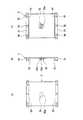
図1〜図4は、本発明に係る携帯機器のスライド機構の一例を示すものである。本発明に係る携帯機器のスライド機構は、携帯機器を構成する第1の筐体と第2の筐体を互いに重ね合わせた状態で相対的に直線方向へ開閉可能にスライドさせるものである。携帯機器としては、特に限定されず、例えば、携帯電話機、ザウルス(商標)等の携帯情報端末機、電卓、ポケットコンピュータ、携帯ゲーム機等が挙げられ、特に携帯電話機が好ましいものとして挙げられる。なお、本発明において携帯機器としては、その他、灰皿、ケース蓋等も含まれる。すなわち、2つの筐体を互いにスライドさせるものであれば特に限定されない。また、本実施の形態では、携帯機器として携帯電話機について説明するが、これに限定されるものではない。 1 to 4 show an example of a slide mechanism of a portable device according to the present invention. The slide mechanism of the portable device according to the present invention slides the first housing and the second housing constituting the portable device so that the first housing and the second housing can be opened and closed relatively in a linear direction. The mobile device is not particularly limited, and examples thereof include a mobile phone, a mobile information terminal such as Zaurus (trademark), a calculator, a pocket computer, a mobile game machine, and the like, and a mobile phone is particularly preferable. In the present invention, the portable device includes an ashtray, a case lid, and the like. That is, there is no particular limitation as long as the two casings are slid with respect to each other. In this embodiment, a mobile phone is described as a mobile device, but the present invention is not limited to this.
本発明に係る携帯機器のスライド機構は、図1〜図4に示すように、第1の筐体2と第2の筐体3のいずれか一方に取り付けられるベース部材5と、このベース部材5に対しスライド可能に係合され、第1の筐体2と第2の筐体3のいずれか他方に取り付けられるスライダー4と、このスライダー4とベース部材5の間に設けられたスライド付勢手段6とからなる。本発明に係る携帯機器のスライド機構1の特徴は、スライド付勢手段6を、ベース部材5とスライダー4のいずれか一方に回動可能に取り付けられている回動アーム7と、ベース部材5とスライダー4のいずれか他方に取り付けられ、回動アーム7に作用して該回動アーム7を所定回動位置から左右いずれの方向へも回動付勢させることによって第1の筐体2と第2の筐体3を所定開閉位置から自動的に開閉させる付勢部材8とで構成したことにある。 As shown in FIGS. 1 to 4, the slide mechanism of the portable device according to the present invention includes a
第1の筐体2は、携帯電話機の送話部を構成するものであり、キーボード部2aやマイク部等を上面に有している。第1の筐体2は、細長の略矩形状に形成されている。第2の筐体3は、同じく携帯電話機の受話部を構成するものであり、LCDなどのディスプレイ部やスピーカー部等を上面に有している。第2の筐体3は、第1の筐体2と略同じ細長の略矩形状に形成されている。なお、第1の筐体2及び第2の筐体3は、図1〜図4においていずれも想像線で記載してある。 The
第1の筐体2の上面には、例えば、ベース部材5(キーベース部材ということがある。)が取り付けられていると共に、第2の筐体3の下面には、例えば、スライダー4(LCDベース部材ということがある。)が取り付けられている。 For example, a base member 5 (sometimes referred to as a key base member) is attached to the upper surface of the
スライダー4は、第2の筐体3の下面の上方に例えばねじやビス等により取り付けられている。スライダー4は、図1〜図4及び図6に示すように、細長の略矩形状に形成されている。スライダー4の両側部は、底面部40に対して直交する一方の方向(図示例では上方)に略直角に折り曲げられて形成されたレール部41、41を有している。すなわち、スライダー4は、略コ字状に例えばステンレス製の金属プレートをプレス加工することにより形成されている。また、スライダー4は、合成樹脂等の成型品であってもよい。なお、図6中、符号48は、スライダー4を第2の筐体3に取り付けるための第1取付孔を示している。この第1取付孔48の内壁には例えばネジ溝が設けられている。 The
また、スライダー4の一方の側部の近傍であってその長手方向の略中央部には、スライド付勢手段6の一端部を取り付けるための取付孔45が設けられている。この取付孔45にシャフト11が取り付けられている。 An
このシャフト11は、図10に示すように、取付孔45の径より小さな例えば若干小さな寸法の径の円柱状のシャフト部11aと、そのシャフト部11aの一端面に同軸上に設けられ、シャフト部11aの径より寸法が小さな径の回動支持部11bと、シャフト部11aの他端面に同軸上に設けられ、取付孔45の径より寸法が大きな径のストッパ部11cとからなる。このシャフト11は、スライダー4の裏面(図示例では上方側の表面)からその回動支持部11bを取付孔45に挿入して回動支持部11bを貫通させると共に、シャフト部11aを取付孔45に挿入し、ストッパ部11cをスライダー4の裏面に当接させてスライダー4に取り付けられる。これにより、シャフト11の回動支持部11bがスライダー4の表面から突出した状態でスライダー4にシャフト11が取り付けられる。 As shown in FIG. 10, the
シャフト部11aの長さ(軸方向の長さ)は、前述のようにシャフト11の取付孔45に取り付けたとき、スライダー4の表面から突出例えば若干突出する寸法で形成されていることが好ましい。また、ストッパ部11cの長さ(軸方向の長さ)は、回動アーム7を回動し得る寸法であれば特に限定されない。 The length of the
スライダー4の両レール部41、41の外面(それぞれ対向する表面とは反対側の表面)には、その長手方向に延びる凹条部としての係合凹部43がそれぞれ形成されている。係合凹部43は、スライダー4の両レール部41、41の長手方向全体にわたって形成されている。スライダー4の一端部には、ストッパ42が設けられ、このストッパ42にスライダー4に係合されているベース部材5が当接してスライダー4の一方側の移動が規制されるようになっている。係合凹部43の他方は開放されている。また、第2の筐体3には、スライダー4を取り付けたとき、そのスライダー4にスライド係合されているベース部材5が当接してスライダー4の他方側の移動を規制する規制部材(図示せず)が設けられている。 Engagement recesses 43 serving as recesses extending in the longitudinal direction are formed on the outer surfaces of the
ベース部材5は、第1の筐体2の上面であってキーボード部2aより上方に例えばねじやビス等により取り付けられている。ベース部材5は、図1〜図4及び図7に示すように、略矩形状に形成されている。ベース部材5はスライダー4にスライド係合するが、そのスライダー4の長手方向に対応するベース部材5の長さは、スライダー4より短い、例えば略1/3の寸法で形成されている。 The
ベース部材5の両側部は、表面に対して直交する一方の方向(図示例では下方)に略直角に折り曲げられて形成されたガイド部51、51を有している。すなわち、ベース部材5は、略コ字状に例えばステンレス製の金属プレートをプレス加工することにより形成されている。また、ベース部材5は、合成樹脂等の成型品であってもよい。ベース部材5の両側部の内面(それぞれ対向する表面)間の長さは、スライダー4の両端部の外面間の長さより大きな、好ましくは若干大きな寸法で形成されている。なお、図1〜図3及び図7中、符号58は、ベース部材5を第1の筐体2に取り付けるための第2取付孔を示している。この第2取付孔58の内壁には例えばネジ溝が設けられている。 Both side portions of the
ベース部材5の両ガイド部51、51の内面には、凸条部としての係合凸部53がそれぞれ設けられている。これらの係合凸部53とスライダー4の係合凹部43がそれぞれ係合して、ベース部材5とスライダー4、すなわち第1の筐体2と第2の筐体3が互いにその長手方向に直線上にスライドするようになっている。このように、スライダー4の両レール部41、41の外側にベース部材5の両ガイド部51、51がスライド係合することにより、スライダー4とベース部材5とが略矩形筒状に形成されている(図4参照)。なお、係合凸部53は、ベース部材5の両ガイド部51、51の長手方向全体に形成されていてもよいし、その一部に間隔をあけて複数形成されていてもよい。また、レール部41、41に係合凹部43を設け、ガイド部51、51に係合凸部53を設けたが、レール部41、41に係合凸部を設け、ガイド部51、51に係合凹部を設けるようにしてもよい。また、レール部41、41及びガイド部51、51にそれぞれ凹部を設け、これら凹部の一方に丸ピンや角ピン等の係合部材を2つ以上挿入して固定し、この係合部材の先端部をそれら凹部の他方に係合させるようにしてもよい。 On the inner surfaces of both guide
係合凹部43に係合凸部53が係合されている状態、すなわち、ベース部材5とスライダー4がスライド係合している状態でベース部材5を第1の筐体2に取り付けたとき、スライダー4は、ベース部材5がストッパ42に当接する状態から規制部材に当接する状態までの範囲でスライド移動し得るようになっている。ベース部材5がストッパ42に当接する状態が、第1の筐体2と第2の筐体3とが重なり合った状態である閉成状態である(図1参照)。また、ベース部材5が規制部材に当接する状態が開成状態である(図3参照)。これら閉成状態と開成状態との間の所定の位置の状態が中立状態である(図2参照)。なお、ベース部材5を第1の筐体2に取り付け、スライダー4を第2の筐体3に取り付けたが、ベース部材5を第2の筐体3に取り付け、スライダー4を第1の筐体2に取り付けるようにしてもよい。 When the
ベース部材5の内面(ガイド部51が立設する側の表面)の略中央部には、図1〜図3、図5及び図7に示すように、付勢部材8の他端部を固定するための固定部55が設けられている。固定部55は、付勢部材8の他端部を着脱可能に固定することができればどのように形成してもよい。固定部55は、例えば、略円形状にベース部材5の内面から突出した装着部55aと、その装着部55aの直径方向にベース部材5の内面に沿って装着部55aを貫通する装着孔55bとからなる。装着部55aは、装着孔55bによって2つの略半円形状に分割されている。固定部55は、ベース部材5の内面に一体的に設けられていてもよいし、溶接等により個別に固定されて設けられていてもよい。 As shown in FIGS. 1 to 3, 5, and 7, the other end portion of the biasing
スライド付勢手段6は、スライダー4とベース部材5のいずれか一方に回動可能に取り付けられている回動アーム7と、スライダー4とベース部材5いずれか他方に取り付けられ、回動アーム7に作用して該回動アーム7を所定回動位置から左右いずれの方向へも回動付勢させることによって第1の筐体2と第2の筐体3を所定開閉位置から自動的に開閉させる付勢部材8とで構成されており、スライダー4の底面部40とベース部材5との間であってスライダー4のレール部41、41とベース部材5のガイド部51、51の間に配設されている。 The slide urging means 6 is attached to either the
回動アーム7の一端部には、図8に示すように、前記シャフト11の回動支持部11bの径より若干小さな径の回動孔71が設けられており、この回動孔71に回動支持部11bが挿入された状態で回動アーム7がスライダー4の内面に対して平行に回動するようになっている。すなわち、回動アーム7は、シャフト11を介してスライダー4の一方の側部近傍に回動可能に枢着されている。 As shown in FIG. 8, a
回動アーム7の長さ(その長手方向の長さ)は、スライダー4の両レール部41、41間の長さより短い寸法で形成されている。また、回動アーム7は、その長手方向の略中間が階段状に形成され、一端部である回動基部と他端部である自由端部との位置がその面方向において異なった位置に形成されている。回動アーム7の自由端部には、回動ピン取付孔72が設けられている。この回動ピン取付孔72に回動アーム7の表面から立設するように回動ピン12が取り付けられている。回動ピン12は、図11に示すように、回動ピン取付孔72の径より大きな寸法の径の円柱状の回動部12aと、その回動部12aの一端面に同軸上に設けられ、回動ピン取付孔72に挿入されて取り付けられる取付部12bとからなる。 The length of the rotating arm 7 (the length in the longitudinal direction) is formed to be shorter than the length between both
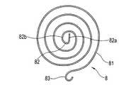
付勢部材8は、回動アーム7に作用して回動アーム7を所定回動位置から左右いずれの方向へも回動付勢させることによって第1の筐体2と第2の筐体3を所定開閉位置から自動的に開閉させるものである。付勢部材8としては、周方向に伸縮する例えばゼンマイ81(渦巻きバネということがある。)等である。なお、付勢部材8としては、ゼンマイ81に限定されるものではなく、他の付勢部材を用いて回動アーム7を作用させるようにしてもよい。 The urging
ゼンマイ81は、図5及び図9に示すように、他端部である基端部82を中心として同一平面上(略同一平面上を含む。)を螺旋状に延びて形成され、一端部である自由端部83に取り付けられた例えば回動アーム7をその螺旋方向とは反対方向の略周方向に付勢するものである。 As shown in FIGS. 5 and 9, the
ゼンマイ81の基端部82は、ベース部材5の内面に設けられた固定部55の装着孔55bに挿入される直線部82aと、その直線部82aから延び固定部55の装着部55aの周囲の一部又は全部に当接又は近接する湾曲部82bとからなり、その固定部55に着脱可能に固定されるようになっている。 A
ゼンマイ81の自由端部83は、螺旋方向とは反対方向に略円形状に折り曲げられ、この自由端部83に回動アーム7に取り付けられた回動ピン12の回動部12aが挿入されて回動ピン12を介して回動アーム7がゼンマイ81の自由端部83に回動可能に枢嵌されるようになっている。自由端部83の内径は、回動ピン12の回動部12aの外径より大きな例えば若干大きな寸法で形成されていることが好ましい。 The
ゼンマイ81の大きさは、ベース部材5の内面上に位置し得る寸法であれば特に限定されない。また、ゼンマイ81は、常に螺旋方向とは反対方向の略周方向に付勢力が生じるように形成されていることが好ましい。このゼンマイ81、回動アーム7、ベース部材5及びスライダー4は、ベース部材5にスライド係合されたスライダー4が閉成状態であるときに、ベース部材5の幅方向の略中央部のストッパ42とは反対側の個所に自由端部83が位置されると共に、その付勢方向が回動アーム7の軸支点側の略周方向aであるように構成されている。また、そのスライダー4を閉成状態から開成状態にベース部材5に対してスライドさせたとき、そのスライドの途中で回動アーム7の先端部にかかる付勢力が回動アーム7の軸支点方向になることがあると共に、回動アーム7の先端部がゼンマイ81の略半円状を移動するように構成されている。また、そのスライダー4が開成状態のときに、ゼンマイ81の中心と回動アーム7の軸支点を連結する直線より回動アーム7の先端部がベース部材5の一方の側部側(回動アーム7が回動可能に取り付けられている近傍の側部側)に位置されるように構成されている。 The size of the
また、ゼンマイ81の材料としては、特に限定されず断面円形の丸線材でも断面矩形の角線材でもよいが、丸線材を用いた場合には荷重をかけるとゼンマイの軸方向に座屈が生じることがあるため、図12に示すように、ベース部材5の内面、例えば、固定部55に座屈を防止するためのプレート85を設けるようにしてもよい。このプレート85は、ベース部材5の内面と略平行に延びる平板状に形成されている。プレート85は、ベース部材5の内面との間にゼンマイ81の厚さ(丸線の直径)より大きな例えば若干大きな寸法の間隔が形成されるように固定部55に設けられていることが好ましい。また、プレート85は、回動アーム7の回動を妨げない形状であると共に、ベース部材5の内面とでゼンマイ81を挟持するような形状に形成されている。 The material of the
次に本発明に係る携帯機器のスライド機構の作用を説明する。 Next, the operation of the slide mechanism of the portable device according to the present invention will be described.
ベース部材5及びスライダー4は、図1〜図4に示すように、例えば、第1の筐体2及び第2の筐体3にそれぞれ取り付けられており、第1の筐体2と第2の筐体3が互いに重なり合った閉成状態にあっては、図1に示すように、スライド付勢手段6のゼンマイ81の付勢力によって、回動アーム7の先端部がスライダー4の一方のレール部41側に付勢されてベース部材5がストッパ42に当接し、ベース部材5とスライダー4とが係止されている。すなわち、回動アーム7のシャフト11を中心にしてゼンマイ81の基端部82をそのシャフト11から離間する方向にゼンマイ81の付勢力によって付勢するので、第1の筐体2と第2の筐体3が互いに重なり合った閉成状態が維持されることになる。なお、この閉成状態をより確実に維持するために、ロック機構を設けるようにしてもよい。 As shown in FIGS. 1 to 4, the
この閉成状態から開成状態となる方向に第1の筐体2、又は第2の筐体3、あるいは両方の筐体2、3をスライドさせると、回動アーム7はシャフト11を軸に回動アーム7の先端部がストッパ42とは反対側に回動する。このとき、ゼンマイ81には、スライドさせるときの力が作用してゼンマイ81が荷重を受けてその付勢力に抗して周方向に伸びる。 When the
そして、図2に示すように、ゼンマイ81の基端部82を中心としたときのゼンマイ81による回動アーム7の自由端部にかかる付勢力がシャフト11方向(略シャフト方向を含む。)になると、ベース部材5にかかるスライド方向の付勢力はなくなる(略なくなるを含む。)。すなわち、スライド力が0になる。この状態(中立状態ということがある。)を過ぎると、回動アーム7の軸支点(シャフト11の中心)とその自由端部との位置が相対的に逆になり、シャフト11を中心にしてゼンマイ81の基端部82がシャフト11から離間する方向にゼンマイ81の付勢力によって付勢されるので、回動アーム7の自由端部がスライダー4の一方のレール部41側に付勢される。その結果、筐体2、3及びベース部材5、スライダー4は自動的にスライド移動すると共に回動アーム7が回動(この場合には揺動もする)して、図3に示すように、ベース部材5が規制部材に当接して開成状態となる。 As shown in FIG. 2, the urging force applied to the free end portion of the
この開成状態においても、スライド付勢手段6の両端部である回動アーム7の軸支点とゼンマイ81の基端部82とが、ゼンマイ81の中心と回動アーム7の軸支点を連結する直線上になく、かつ、回動アーム7の先端部がスライダー4の一方のレール部41側に位置されているので、シャフト11を中心にしてゼンマイ81の基端部82がシャフト11から離間する方向にゼンマイ81の付勢力によって付勢される。その結果、ベース部材5が規制部材に当接した状態、すなわち、開成状態が維持されることになる。これにより、第1の筐体2の上面に設けたキーボード部2aが露出するので、通話及びキーボード操作が可能となる。なお、この開成状態をより確実に維持するために、ロック機構を設けるようにしてもよい。よって、閉成状態から開成状態にスライド移動させるときに半自動でスライド動作を行えることになる。 Even in this open state, the shaft fulcrum of the
開成状態から閉成状態となる方向に第1の筐体2、又は第2の筐体3、あるいは両方の筐体2、3をスライドさせると、ゼンマイ81が付勢力に抗して周方向伸びる。中立状態を過ぎて、回動アーム7の軸支点とその先端部との位置が相対的に逆になると、シャフト11を中心にしてゼンマイ81の基端部82がシャフト11から離間する方向にゼンマイ81の付勢力によって付勢される。その結果、筐体2、3及びベース部材5、スライダー4は自動的にスライド移動すると共に回動アーム7が回動して、筐体2、3は自動的にスライド移動してベース部材5がストッパ42に当接して閉成状態となる。よって、開成状態から閉成状態にスライド移動させるときに半自動でスライド動作を行えることになる。 When the
したがって、本発明に係る携帯機器のスライド機構1は、回動アーム7とゼンマイ81という簡単な構成で、第1の筐体2と第2の筐体3とを半自動的にスライドさせることができ、操作性が向上するものである。 Therefore, the slide mechanism 1 of the portable device according to the present invention can slide the
また、回動アーム7とゼンマイ81とを用いて半自動でスライド動作を行うので、部品点数が少なくて済み、コスト削減及び小型化を図ることが可能となる。また、ゼンマイ81等の付勢部材8の弾性特性等と回動アーム7の位置及び長さを変えることにより、様々なスライド動作を設定することができる。例えば、閉成状態及び開成状態におけるスライド付勢手段6の付勢力を増大させることにより、閉成状態及び開成状態を維持する力を上げることができ、確実に閉成状態及び開成状態を維持することができることになる。また、カム等の摺動部材を用いていないので、摩擦による動作力の低減が起こることがない。 Further, since the sliding operation is performed semi-automatically using the
以上説明したように本発明に係るスライド機構は、構成が簡単な上に、第1の筐体と第2の筐体とを半自動的にスライドさせることができるので、操作性が向上し、携帯端末の中でもとくに携帯電話機のスライド機構として好適に用いられるものである。 As described above, the slide mechanism according to the present invention has a simple configuration and can slide the first housing and the second housing semi-automatically, improving operability and carrying. Among terminals, it is preferably used as a slide mechanism for mobile phones.
1 スライド機構
2 第1の筐体
3 第2の筐体
4 スライダー
5 ベース部材
6 スライド付勢手段
7 回動アーム
8 付勢部材
11 シャフト
12 回動ピン
40 底面部
41 レール部
43 係合凹部
45 取付孔
51 ガイド部
53 係合凸部
55 固定部
81 ゼンマイ
82 基端部
83 自由端部DESCRIPTION OF SYMBOLS 1
Claims (5)
Translated fromJapanese前記第1の筐体と前記第2の筐体のいずれか一方に取り付けられるベース部材と、このベース部材に対しスライド可能に係合され、前記第1の筐体と前記第2の筐体のいずれか他方に取り付けられるスライダーと、このスライダーと前記ベース部材の間に設けられたスライド付勢手段とからなり、
このスライド付勢手段を、前記ベース部材と前記スライダーのいずれか一方に回動可能に取り付けられている回動アームと、前記ベース部材と前記スライダーのいずれか他方に取り付けられ、前記回動アームに作用して該回動アームを所定回動位置から左右いずれの方向へも回動付勢させることによって前記第1の筐体と前記第2の筐体を所定開閉位置から自動的に開閉させる付勢部材とで構成したことを特徴とする、携帯機器のスライド機構。A slide mechanism that slides so that the first casing and the second casing constituting the portable device can be opened and closed relatively in a linear direction in a state where the first casing and the second casing overlap each other.
A base member attached to one of the first casing and the second casing, and slidably engaged with the base member, and the first casing and the second casing A slider attached to one of the other, and a slide biasing means provided between the slider and the base member,
The slide urging means is attached to one of the base member and the slider so as to be pivotable, and is attached to the other of the base member and the slider. The first and second housings are automatically opened and closed from a predetermined opening / closing position by acting and urging the rotation arm in either direction from the predetermined rotation position. A sliding mechanism for a portable device, characterized by comprising a force member.
Priority Applications (5)
| Application Number | Priority Date | Filing Date | Title |
|---|---|---|---|
| JP2004290272AJP2006108881A (en) | 2004-10-01 | 2004-10-01 | Slide mechanism of mobile apparatus and mobile phone |
| KR1020040089783AKR100681893B1 (en) | 2004-10-01 | 2004-11-05 | Slide device and mobile phone of mobile device |
| US11/114,834US7463913B2 (en) | 2004-10-01 | 2005-04-26 | Slide mechanism of portable device and portable telephone |
| CNA2005100734400ACN1756469A (en) | 2004-10-01 | 2005-05-24 | Slide mechanism of portable device and portable telephone |
| TW094124185ATWI275288B (en) | 2004-10-01 | 2005-07-15 | Slide mechanism of mobile equipment and mobile telephone |
Applications Claiming Priority (1)
| Application Number | Priority Date | Filing Date | Title |
|---|---|---|---|
| JP2004290272AJP2006108881A (en) | 2004-10-01 | 2004-10-01 | Slide mechanism of mobile apparatus and mobile phone |
Publications (1)
| Publication Number | Publication Date |
|---|---|
| JP2006108881Atrue JP2006108881A (en) | 2006-04-20 |
Family
ID=36126213
Family Applications (1)
| Application Number | Title | Priority Date | Filing Date |
|---|---|---|---|
| JP2004290272APendingJP2006108881A (en) | 2004-10-01 | 2004-10-01 | Slide mechanism of mobile apparatus and mobile phone |
Country Status (5)
| Country | Link |
|---|---|
| US (1) | US7463913B2 (en) |
| JP (1) | JP2006108881A (en) |
| KR (1) | KR100681893B1 (en) |
| CN (1) | CN1756469A (en) |
| TW (1) | TWI275288B (en) |
Cited By (5)
| Publication number | Priority date | Publication date | Assignee | Title |
|---|---|---|---|---|
| JP2007166216A (en)* | 2005-12-13 | 2007-06-28 | Yamamoto Seimitsu:Kk | Mobile electronic apparatus |
| KR100822694B1 (en) | 2007-01-05 | 2008-04-17 | (주)제이엠씨 | Elastic module using spring-loaded spring and slide device of sliding type mobile phone |
| JP2009071806A (en)* | 2007-09-10 | 2009-04-02 | Samkwang Ind Co Ltd | Mobile communication terminal unit |
| JP2009543006A (en)* | 2006-07-07 | 2009-12-03 | ピーアンドテル インコーポレイテッド | Torsion spring, elastic device, slide opening and closing device, and portable device using this device |
| US8554289B2 (en) | 2008-02-22 | 2013-10-08 | Nec Corporation | Portable apparatus having a slide mechanism for an upper casing and a lower casing |
Families Citing this family (35)
| Publication number | Priority date | Publication date | Assignee | Title |
|---|---|---|---|---|
| TWM260061U (en)* | 2004-06-11 | 2005-03-21 | Quanta Comp Inc | Automatic sliding mechanism |
| US20060056141A1 (en)* | 2004-09-13 | 2006-03-16 | Nokia Corporation | Portable electronic device |
| KR200382520Y1 (en)* | 2005-02-01 | 2005-04-20 | 피닉스코리아 주식회사 | Sliding type opening and closing apparatus for use in portable telephone |
| US8463439B2 (en) | 2009-03-31 | 2013-06-11 | Intuitive Surgical Operations, Inc. | Optic fiber connection for a force sensing instrument |
| TW200644566A (en)* | 2005-06-02 | 2006-12-16 | Benq Corp | Portable electronic device |
| US20070060220A1 (en)* | 2005-09-14 | 2007-03-15 | An-Szu Hsu | Gliding structure for glide-open type mobile phone |
| KR101299323B1 (en)* | 2005-09-20 | 2013-08-26 | 스가쓰네 고우교 가부시키가이샤 | Mobile device |
| CN101248585B (en)* | 2005-09-23 | 2011-01-26 | 安费诺凤凰株式会社 | Sliding opening and closing device for use in portable telephones |
| US20070121279A1 (en)* | 2005-11-25 | 2007-05-31 | Motorola, Inc. | Translating axes slide mechanism |
| USD550192S1 (en)* | 2005-12-21 | 2007-09-04 | Samsung Electronics Co., Ltd. | Mobile phone |
| KR100778030B1 (en)* | 2006-06-05 | 2007-11-22 | 엘지전자 주식회사 | Mobile communication terminal having a slide module |
| KR100714230B1 (en)* | 2006-06-22 | 2007-05-02 | 엠알디 주식회사 | Double Slide Hinge Module For Mobile Phone |
| US7953464B2 (en)* | 2006-07-13 | 2011-05-31 | Samsung Electronics Co., Ltd. | Sliding-type portable terminal |
| KR100770855B1 (en)* | 2006-10-31 | 2007-10-26 | 삼성전자주식회사 | Spring and semi-automatic sliding device using same and sliding type portable communication terminal using same |
| KR100803784B1 (en)* | 2006-11-24 | 2008-02-15 | 삼성전자주식회사 | Sliding / swing module and portable terminal having the same |
| KR100873091B1 (en)* | 2007-04-06 | 2008-12-09 | (주)하이텍파츠 | Flexible link assembly with a plurality of springs and slider assembly having the same |
| KR100872208B1 (en)* | 2007-05-16 | 2008-12-05 | 정영조 | Opening and closing device of mobile phone with slide cover |
| KR100842631B1 (en)* | 2007-06-11 | 2008-06-30 | 삼성전자주식회사 | Sliding module of portable electronic device with locking function |
| JP4796544B2 (en)* | 2007-06-12 | 2011-10-19 | 富士通東芝モバイルコミュニケーションズ株式会社 | Electronics |
| WO2009008655A2 (en)* | 2007-07-09 | 2009-01-15 | Shell-Line | Actuator and spring used therefor |
| JP5029335B2 (en)* | 2007-12-07 | 2012-09-19 | 富士通モバイルコミュニケーションズ株式会社 | Mobile device |
| CN101472430B (en)* | 2007-12-24 | 2011-12-14 | 鸿富锦精密工业(深圳)有限公司 | Sliding mechanism |
| US8060163B2 (en)* | 2008-03-11 | 2011-11-15 | Sony Ericsson Mobile Communication Ab | Seamless slider |
| JP2009251080A (en)* | 2008-04-02 | 2009-10-29 | Sony Ericsson Mobilecommunications Japan Inc | Lock mechanism, slide apparatus, and mobile handset apparatus |
| JP5102688B2 (en)* | 2008-04-23 | 2012-12-19 | 加藤電機株式会社 | Opening and closing device for portable device and portable device |
| USD594842S1 (en)* | 2008-06-12 | 2009-06-23 | Samsung Electronics Co., Ltd. | Portable phone |
| CN101652045B (en)* | 2008-08-15 | 2012-03-14 | 深圳富泰宏精密工业有限公司 | Slip cover type electronic device |
| TWM353403U (en)* | 2008-11-14 | 2009-03-21 | Ascend Top Entpr Co Ltd | Assembling structure |
| CN101932215B (en)* | 2008-12-31 | 2014-03-26 | 深圳富泰宏精密工业有限公司 | Sliding mechanism applied to portable electronic device |
| JP5110024B2 (en)* | 2009-03-31 | 2012-12-26 | 富士通株式会社 | Information processing terminal |
| KR101554187B1 (en) | 2009-05-11 | 2015-09-18 | 엘지전자 주식회사 | Hinge unit and portable terminal using the same |
| USD616853S1 (en)* | 2009-06-05 | 2010-06-01 | Samsung Electronics Co., Ltd. | Mobile phone |
| DE202009014628U1 (en)* | 2009-10-29 | 2010-01-07 | Bornbex Handels- Und Vertriebs Gmbh & Co. Kg | Closure device for an image capture device |
| KR101789329B1 (en)* | 2011-02-07 | 2017-10-23 | 삼성전자주식회사 | Slide type portable terminal |
| CN105141815B (en)* | 2015-09-02 | 2018-07-31 | 小米科技有限责任公司 | Camera automatic pop-up device and terminal |
Citations (5)
| Publication number | Priority date | Publication date | Assignee | Title |
|---|---|---|---|---|
| JP2001060996A (en)* | 1999-08-24 | 2001-03-06 | Strawberry Corporation:Kk | Opening/closing structure of flip attached to portable telephone set |
| JP2003083235A (en)* | 2001-09-12 | 2003-03-19 | Seiko Epson Corp | Spring drive mechanism and device using the same |
| JP2003083375A (en)* | 2001-09-12 | 2003-03-19 | Seiko Epson Corp | Spring mechanism module and device using the same |
| JP2004253526A (en)* | 2003-02-19 | 2004-09-09 | Strawberry Corporation | Slide device and electronic instrument employing slide device |
| JP2007503752A (en)* | 2003-08-25 | 2007-02-22 | エムツゥシス カンパニー リミテッド | Slide opening / closing device and portable terminal equipped with the same |
Family Cites Families (10)
| Publication number | Priority date | Publication date | Assignee | Title |
|---|---|---|---|---|
| KR200184936Y1 (en) | 2000-01-10 | 2000-06-01 | 김용수 | Cellular phone |
| FI112422B (en)* | 2000-04-28 | 2003-11-28 | Nokia Corp | Telescope structure for a telephone set |
| JP3856682B2 (en) | 2001-10-15 | 2006-12-13 | 加藤電機株式会社 | Slide mechanism |
| KR100605862B1 (en)* | 2002-07-02 | 2006-07-31 | 삼성전자주식회사 | Sliding type wireless terminal |
| FI118669B (en)* | 2003-04-01 | 2008-01-31 | Samsung Electro Mech | Sliding type mobile phone and its sliding method |
| US7003104B2 (en)* | 2003-10-13 | 2006-02-21 | Hanbit Precision Co., Ltd. | Apparatus for opening and closing cover of cellular phone |
| KR200346618Y1 (en) | 2004-01-09 | 2004-04-01 | 모아테크 주식회사 | Slide type portable terminal |
| KR200357158Y1 (en) | 2004-05-12 | 2004-07-30 | (주)두성테크 | Sliding construction of wireless hand phone of sliding type |
| KR100678516B1 (en)* | 2004-06-15 | 2007-02-07 | 주식회사 우영 | Sliding device of sliding type mobile phone using spring |
| KR200365340Y1 (en) | 2004-07-13 | 2004-10-20 | 주식회사 대성텔레콤 | A semi automatic slide hinge structure of mobile phone |
- 2004
- 2004-10-01JPJP2004290272Apatent/JP2006108881A/enactivePending
- 2004-11-05KRKR1020040089783Apatent/KR100681893B1/ennot_activeExpired - Fee Related
- 2005
- 2005-04-26USUS11/114,834patent/US7463913B2/ennot_activeExpired - Fee Related
- 2005-05-24CNCNA2005100734400Apatent/CN1756469A/enactivePending
- 2005-07-15TWTW094124185Apatent/TWI275288B/ennot_activeIP Right Cessation
Patent Citations (5)
| Publication number | Priority date | Publication date | Assignee | Title |
|---|---|---|---|---|
| JP2001060996A (en)* | 1999-08-24 | 2001-03-06 | Strawberry Corporation:Kk | Opening/closing structure of flip attached to portable telephone set |
| JP2003083235A (en)* | 2001-09-12 | 2003-03-19 | Seiko Epson Corp | Spring drive mechanism and device using the same |
| JP2003083375A (en)* | 2001-09-12 | 2003-03-19 | Seiko Epson Corp | Spring mechanism module and device using the same |
| JP2004253526A (en)* | 2003-02-19 | 2004-09-09 | Strawberry Corporation | Slide device and electronic instrument employing slide device |
| JP2007503752A (en)* | 2003-08-25 | 2007-02-22 | エムツゥシス カンパニー リミテッド | Slide opening / closing device and portable terminal equipped with the same |
Cited By (6)
| Publication number | Priority date | Publication date | Assignee | Title |
|---|---|---|---|---|
| JP2007166216A (en)* | 2005-12-13 | 2007-06-28 | Yamamoto Seimitsu:Kk | Mobile electronic apparatus |
| JP2009543006A (en)* | 2006-07-07 | 2009-12-03 | ピーアンドテル インコーポレイテッド | Torsion spring, elastic device, slide opening and closing device, and portable device using this device |
| US8121658B2 (en) | 2006-07-07 | 2012-02-21 | P & Tel Inc. | Torsion spring, elastic device and sliding apparatus and portable appliance utilizing the device |
| KR100822694B1 (en) | 2007-01-05 | 2008-04-17 | (주)제이엠씨 | Elastic module using spring-loaded spring and slide device of sliding type mobile phone |
| JP2009071806A (en)* | 2007-09-10 | 2009-04-02 | Samkwang Ind Co Ltd | Mobile communication terminal unit |
| US8554289B2 (en) | 2008-02-22 | 2013-10-08 | Nec Corporation | Portable apparatus having a slide mechanism for an upper casing and a lower casing |
Also Published As
| Publication number | Publication date |
|---|---|
| TW200612713A (en) | 2006-04-16 |
| CN1756469A (en) | 2006-04-05 |
| US7463913B2 (en) | 2008-12-09 |
| KR100681893B1 (en) | 2007-02-12 |
| TWI275288B (en) | 2007-03-01 |
| KR20060029586A (en) | 2006-04-06 |
| US20060073858A1 (en) | 2006-04-06 |
Similar Documents
| Publication | Publication Date | Title |
|---|---|---|
| JP2006108881A (en) | Slide mechanism of mobile apparatus and mobile phone | |
| JP4845558B2 (en) | Portable device | |
| JP2005210649A (en) | Sliding mechanism of mobile terminal | |
| JP5599226B2 (en) | Switchgear | |
| JP5085343B2 (en) | Mobile device slide mechanism and portable device | |
| JP3972795B2 (en) | Switchgear | |
| JP2005061559A (en) | Slide hinge for compact information terminal | |
| JP4325540B2 (en) | Switchgear | |
| JP2005117450A (en) | Portable terminal device | |
| JP2009299861A (en) | Hinge device | |
| JP2006081107A (en) | Sliding mechanism for mobile apparatus, and portable telephone set | |
| JP2006270804A (en) | Sliding mechanism of portable device and cellular phone | |
| JP5129686B2 (en) | Portable device and opening / closing device of the portable device | |
| JP2006173794A (en) | Slide mechanism for mobile unit and mobile phone | |
| JP4808800B2 (en) | Mobile terminal device | |
| KR100675731B1 (en) | Slide up switchgear for communication terminal | |
| JP5016395B2 (en) | Hinge device for portable device and portable device | |
| JP2008275136A (en) | Energizing member for slide mechanism, slide mechanism for portable device and portable device | |
| JP4537930B2 (en) | Horizontal rotation mechanism for portable devices | |
| JP4898584B2 (en) | Mobile device | |
| JP2009147565A (en) | Mobile device and opening/closing device of mobile device | |
| JP2008153599A (en) | Portable device | |
| JP4738161B2 (en) | Mobile device slide mechanism and mobile phone | |
| JP2009052581A (en) | Hinge unit and collapsible electronic equipment | |
| KR100610373B1 (en) | Bidirectional hinge device and portable terminal having same |
Legal Events
| Date | Code | Title | Description |
|---|---|---|---|
| A621 | Written request for application examination | Free format text:JAPANESE INTERMEDIATE CODE: A621 Effective date:20070914 | |
| A977 | Report on retrieval | Free format text:JAPANESE INTERMEDIATE CODE: A971007 Effective date:20090604 | |
| A131 | Notification of reasons for refusal | Free format text:JAPANESE INTERMEDIATE CODE: A131 Effective date:20090616 | |
| A02 | Decision of refusal | Free format text:JAPANESE INTERMEDIATE CODE: A02 Effective date:20091027 |