JP2006106917A - Wireless unit for drive shaft, lid for bearing cup grease injection hole, and drive shaft monitoring system - Google Patents
Wireless unit for drive shaft, lid for bearing cup grease injection hole, and drive shaft monitoring systemDownload PDFInfo
- Publication number
- JP2006106917A JP2006106917AJP2004289606AJP2004289606AJP2006106917AJP 2006106917 AJP2006106917 AJP 2006106917AJP 2004289606 AJP2004289606 AJP 2004289606AJP 2004289606 AJP2004289606 AJP 2004289606AJP 2006106917 AJP2006106917 AJP 2006106917A
- Authority
- JP
- Japan
- Prior art keywords
- drive shaft
- unit
- battery
- power source
- wireless unit
- Prior art date
- Legal status (The legal status is an assumption and is not a legal conclusion. Google has not performed a legal analysis and makes no representation as to the accuracy of the status listed.)
- Withdrawn
Links
Images


Classifications
- F—MECHANICAL ENGINEERING; LIGHTING; HEATING; WEAPONS; BLASTING
- F16—ENGINEERING ELEMENTS AND UNITS; GENERAL MEASURES FOR PRODUCING AND MAINTAINING EFFECTIVE FUNCTIONING OF MACHINES OR INSTALLATIONS; THERMAL INSULATION IN GENERAL
- F16D—COUPLINGS FOR TRANSMITTING ROTATION; CLUTCHES; BRAKES
- F16D3/00—Yielding couplings, i.e. with means permitting movement between the connected parts during the drive
- F16D3/16—Universal joints in which flexibility is produced by means of pivots or sliding or rolling connecting parts
- F16D3/26—Hooke's joints or other joints with an equivalent intermediate member to which each coupling part is pivotally or slidably connected
- F16D3/38—Hooke's joints or other joints with an equivalent intermediate member to which each coupling part is pivotally or slidably connected with a single intermediate member with trunnions or bearings arranged on two axes perpendicular to one another
- F16D3/40—Hooke's joints or other joints with an equivalent intermediate member to which each coupling part is pivotally or slidably connected with a single intermediate member with trunnions or bearings arranged on two axes perpendicular to one another with intermediate member provided with two pairs of outwardly-directed trunnions on intersecting axes
- F16D3/41—Hooke's joints or other joints with an equivalent intermediate member to which each coupling part is pivotally or slidably connected with a single intermediate member with trunnions or bearings arranged on two axes perpendicular to one another with intermediate member provided with two pairs of outwardly-directed trunnions on intersecting axes with ball or roller bearings
- F—MECHANICAL ENGINEERING; LIGHTING; HEATING; WEAPONS; BLASTING
- F16—ENGINEERING ELEMENTS AND UNITS; GENERAL MEASURES FOR PRODUCING AND MAINTAINING EFFECTIVE FUNCTIONING OF MACHINES OR INSTALLATIONS; THERMAL INSULATION IN GENERAL
- F16D—COUPLINGS FOR TRANSMITTING ROTATION; CLUTCHES; BRAKES
- F16D2300/00—Special features for couplings or clutches
- F16D2300/18—Sensors; Details or arrangements thereof
Landscapes
- Engineering & Computer Science (AREA)
- General Engineering & Computer Science (AREA)
- Mechanical Engineering (AREA)
- Arrangements For Transmission Of Measured Signals (AREA)
Abstract
Description
Translated fromJapanese本発明は、圧延設備などの駆動軸に関するデータを送信する駆動軸用ワイヤレスユニット、上記データの送信が可能なベアリングカップグリース注入孔用蓋、及び上記駆動軸を監視する駆動軸監視システムに関する。 The present invention relates to a drive shaft wireless unit that transmits data related to a drive shaft such as rolling equipment, a bearing cup grease injection lid that can transmit the data, and a drive shaft monitoring system that monitors the drive shaft.
例えば鉄鋼用圧延設備では、圧延ローラと駆動モータとの間に接続された駆動軸の途中部分に十字軸継手を設けることにより、上記ローラが圧延中の鋼材に対し上下に動くのを許容した状態で、圧延処理を行っている。また、このような圧延設備では、その駆動軸の動作状態が圧延処理される鋼材品質に直結することから当該駆動軸を監視する監視システムを構築することが要望されており、さらには駆動軸自体が回転動作するために有線方式の送信機を用いることは困難であるということから、無線方式の送信機(ワイヤレスユニット)にてセンサ検出結果を送信させることが検討されている。
一方、十字軸継手を備えた駆動軸に取り付けられる従来システムには、例えば下記特許文献1に記載されているように、十字軸継手での温度を検出する温度センサとこのセンサ出力を無線送信するワイヤレスユニットとを設けたものが提案されている。For example, in a steel rolling facility, a cross shaft joint is provided in the middle part of the drive shaft connected between the rolling roller and the drive motor, thereby allowing the roller to move up and down with respect to the steel material being rolled. In the rolling process. In such rolling equipment, since the operating state of the drive shaft is directly linked to the quality of the steel material to be rolled, it is desired to construct a monitoring system for monitoring the drive shaft, and further the drive shaft itself. Since it is difficult to use a wired-type transmitter for rotating, the transmission of sensor detection results using a wireless-type transmitter (wireless unit) has been studied.
On the other hand, in a conventional system attached to a drive shaft provided with a cross shaft joint, for example, as described in
ところで、上記のような従来システムでは、その電力源として電池を用いたバッテリー電源が使用されており、このバッテリー電源からの電力供給にてワイヤレスユニット及びこのユニットに接続されたセンサを動作していた。このため、バッテリー電源の寿命が短く早期に電池交換を行う必要があった。とりわけ、圧延設備などの駆動軸のように、センサの監視対象となる物理量が比較的高周波なものである場合、その監視精度を向上させるためには、センサの監視結果を高い周波数でサンプリングしてデータ処理する必要がある。すなわち、上記のような駆動軸に用いられるワイヤレスユニットでは、上記監視結果を高速処理して送信することが要求されるため、当該ワイヤレスユニットでの電力消費が大きく、バッテリー電源の長寿命化を行うことが困難であるという問題点を生じた。 By the way, in the conventional system as described above, a battery power source using a battery is used as the power source, and the wireless unit and the sensor connected to the unit are operated by power supply from the battery power source. . For this reason, it was necessary to replace the battery at an early stage because the life of the battery power source was short. In particular, when the physical quantity to be monitored by the sensor is a relatively high frequency, such as a drive shaft of a rolling facility, in order to improve the monitoring accuracy, the sensor monitoring result is sampled at a high frequency. Data needs to be processed. That is, in the wireless unit used for the drive shaft as described above, since the monitoring result is required to be processed and transmitted at high speed, the power consumption in the wireless unit is large and the life of the battery power source is extended. The problem was that it was difficult.
上記のような従来の問題点に鑑み、本発明は、圧延設備の駆動軸などに用いられる場合でも、バッテリー電源の電池消耗を低減することができ、よってバッテリー電源の長寿命化を図ることができる駆動軸用ワイヤレスユニット、及びこれを用いたベアリングカップグリース注入孔用蓋並びに駆動軸監視システムを提供することを目的とする。 In view of the above-described conventional problems, the present invention can reduce battery consumption of a battery power supply even when used for a drive shaft of a rolling facility, and thus can extend the life of the battery power supply. An object of the present invention is to provide a drive shaft wireless unit that can be used, a bearing cup grease filling lid using the same, and a drive shaft monitoring system.
本発明の駆動軸用ワイヤレスユニットは、バッテリー電源を有し、駆動軸に取り付けられるワイヤレスユニットであって、
発電手段と、前記駆動軸の損傷を検出するためのセンサに接続されてそのセンサからの検出データを送信する送信手段とを備えたことを特徴とするものである。
上記のように構成された駆動軸用ワイヤレスユニットでは、発電手段が設けられているので、この発電手段によって発電した電力を上記送信手段に供給することができ、バッテリー電源の電池消耗を低減することができる。The wireless unit for the drive shaft of the present invention is a wireless unit having a battery power source and attached to the drive shaft,
It is characterized by comprising power generation means and transmission means connected to a sensor for detecting damage to the drive shaft and transmitting detection data from the sensor.
In the drive shaft wireless unit configured as described above, since the power generation means is provided, the power generated by the power generation means can be supplied to the transmission means, thereby reducing battery consumption of the battery power supply. Can do.
また、駆動軸用ワイヤレスユニットにおいて、前記バッテリー電源が、一次電池を用いて構成されるとともに、
前記発電手段が、前記バッテリー電源の補助電源に使用され、かつ、この補助電源からの電力供給と前記一次電池からの電力供給とを切り替える切替手段を設けることが好ましい。
この場合、切替手段が補助電源からの電力供給と一次電池からの電力供給とを切り替えるので、当該一次電池を用いたバッテリー電源の電池消耗をより確実に低減することができる。Further, in the drive shaft wireless unit, the battery power source is configured using a primary battery,
It is preferable that the power generation means is used as an auxiliary power source for the battery power source, and further includes a switching means for switching between power supply from the auxiliary power source and power supply from the primary battery.
In this case, since the switching unit switches between the power supply from the auxiliary power supply and the power supply from the primary battery, the battery consumption of the battery power supply using the primary battery can be more reliably reduced.
また、上記駆動軸用ワイヤレスユニットにおいて、前記発電手段が、ソーラーパネルを用いて構成されてもよい。
この場合、ソーラーパネルによって発電された電力によって上記送信手段を動作させることができ、バッテリー電源の電池消耗を低減することができる。In the drive shaft wireless unit, the power generation means may be configured using a solar panel.
In this case, the transmission means can be operated by the electric power generated by the solar panel, and battery consumption of the battery power source can be reduced.
また、上記駆動軸用ワイヤレスユニットにおいて、前記駆動軸は、ベアリングカップを有する十字軸継手を備えるとともに、
前記バッテリー電源及び前記送信手段が、前記ベアリングカップに形成されたグリース注入用の孔の内部に配置され、前記ソーラーパネルが、前記ベアリングカップの表面に取り付けられていることが好ましい。
この場合、圧延設備などのように十字軸継手の十字軸が外部にほとんど露出されない駆動軸に用いるときでも、上記バッテリー電源及び送信手段を容易に取り付けることができるとともに、ベアリングカップ表面に取り付けたソーラーパネルによってバッテリー電源の電池消耗を確実に低減することができる。In the drive shaft wireless unit, the drive shaft includes a cross joint having a bearing cup,
It is preferable that the battery power source and the transmission unit are disposed inside a grease injection hole formed in the bearing cup, and the solar panel is attached to the surface of the bearing cup.
In this case, even when the cross shaft of the cross shaft joint is used as a drive shaft that is hardly exposed to the outside, such as rolling equipment, the battery power source and the transmission means can be easily attached, and the solar power attached to the bearing cup surface. The panel can reliably reduce battery consumption of the battery power supply.
また、上記駆動軸用ワイヤレスユニットにおいて、前記ソーラーパネルと前記ベアリングカップの表面との間に防振材を設けてもよい。
この場合、上記防振材により、駆動軸の回転動作に伴って発生する振動等の衝撃でソーラーパネルが破損するのを防ぐことができる。In the drive shaft wireless unit, a vibration isolating material may be provided between the solar panel and the surface of the bearing cup.
In this case, it is possible to prevent the solar panel from being damaged by an impact such as vibration generated along with the rotation operation of the drive shaft by the vibration isolating material.
また、上記駆動軸用ワイヤレスユニットにおいて、前記発電手段は、前記駆動軸の回転動作に応じて発電することが好ましい。
この場合、発電手段が駆動軸の動作時に自動的に発電することができ、上記バッテリー電源の電池消耗を低減することができる。In the drive shaft wireless unit, it is preferable that the power generation means generate power according to a rotation operation of the drive shaft.
In this case, the power generation means can automatically generate power during operation of the drive shaft, and battery consumption of the battery power source can be reduced.
また、上記駆動軸用ワイヤレスユニットにおいて、前記発電手段が、前記駆動軸の回転動作に応じて歪むことにより、発電する圧電素子を用いて構成されてもよい。
この場合、圧電素子によって発電された電力によって上記送信手段を動作させることができ、バッテリー電源の電池消耗を低減することができる。In the drive shaft wireless unit, the power generation means may be configured using a piezoelectric element that generates power by being distorted in accordance with the rotation operation of the drive shaft.
In this case, the transmission means can be operated by the electric power generated by the piezoelectric element, and battery consumption of the battery power source can be reduced.
また、上記駆動軸用ワイヤレスユニットにおいて、前記発電手段には、前記駆動軸の回転動作に応じて移動し、前記圧電素子と衝突することによって当該圧電素子を歪ませる動作体が設けられてもよい。
この場合、上記動作体との衝突によって圧電素子を大きく歪ませることができ、当該圧電素子に効率よく電力を発生させることができ、バッテリー電源の電池消耗をより低減することができる。In the drive shaft wireless unit, the power generation means may be provided with an operating body that moves according to the rotation operation of the drive shaft and distorts the piezoelectric element by colliding with the piezoelectric element. .
In this case, the piezoelectric element can be greatly distorted by the collision with the operating body, power can be efficiently generated in the piezoelectric element, and battery consumption of the battery power source can be further reduced.
また、上記駆動軸用ワイヤレスユニットにおいて、前記駆動軸は、ベアリングカップを有する十字軸継手を備えるとともに、
前記バッテリー電源及び前記送信手段が、前記ベアリングカップに形成されたグリース注入用の孔の内部に配置され、前記圧電素子が、前記ベアリングカップに取り付けられていることが好ましい。
この場合、圧延設備などのように十字軸継手の十字軸が外部にほとんど露出されない駆動軸に用いるときでも、上記バッテリー電源及び送信手段を容易に取り付けることができるとともに、ベアリングカップに取り付けた圧電素子によってバッテリー電源の電池消耗を確実に低減することができる。In the drive shaft wireless unit, the drive shaft includes a cross joint having a bearing cup,
It is preferable that the battery power source and the transmission unit are disposed inside a grease injection hole formed in the bearing cup, and the piezoelectric element is attached to the bearing cup.
In this case, even when the cross shaft of the cross shaft joint is used as a drive shaft that is hardly exposed to the outside, such as rolling equipment, the battery power source and the transmission means can be easily attached, and the piezoelectric element attached to the bearing cup Thus, battery consumption of the battery power source can be reliably reduced.
また、本発明のベアリングカップグリース注入孔用蓋は、十字軸継手を備えた駆動軸において、前記十字軸継手のベアリングカップに形成されたグリース注入用の孔に取り付けられる蓋であって、
バッテリー電源と、発電手段と、前記駆動軸の損傷を検出するためのセンサに接続されてそのセンサからの検出データを送信する送信手段とを備えるワイヤレスユニットが装着されていることを特徴とするものである。
上記のように構成されたベアリングカップグリース注入孔用蓋では、バッテリー電源、発電手段、及び送信手段を有し、上記センサからのデータ送信が可能なワイヤレスユニットが当該蓋に装着されているので、既設の駆動軸の十字軸継手に形成されたグリース注入用の孔に上記ワイヤレスユニットを取り付けることができる。従って、損傷の進行度合いを監視できなかった駆動軸に対しても、バッテリー電源の電池消耗を低減したワイヤレスユニットにより、その監視を行うことが可能となる。Further, the bearing cup grease injection hole lid of the present invention is a lid attached to a grease injection hole formed in a bearing cup of the cross shaft joint in a drive shaft provided with a cross shaft joint,
A wireless unit comprising a battery power supply, a power generation means, and a transmission means connected to a sensor for detecting damage to the drive shaft and transmitting detection data from the sensor is mounted. It is.
The lid for the bearing cup grease injection hole configured as described above has a battery power source, power generation means, and transmission means, and a wireless unit capable of transmitting data from the sensor is mounted on the lid. The wireless unit can be attached to a grease injection hole formed in a cross shaft joint of an existing drive shaft. Accordingly, even a drive shaft whose progress of damage cannot be monitored can be monitored by a wireless unit with reduced battery power consumption.
また、本発明の駆動軸監視システムは、駆動軸側に設けられた子機と、この子機と無線通信が可能な親機とを有し、前記子機からの送信信号を基に前記駆動軸を監視する監視システムであって、
前記子機に、上記いずれかの駆動軸用ワイヤレスユニットを使用したことを特徴とするものである。
上記のように構成された駆動軸監視システムでは、バッテリー電源の電池消耗を低減したワイヤレスユニットを備えているので、電池交換作業の頻度が少なく長期間のメンテナンスフリー性を有するシステムを構築することができる。The drive shaft monitoring system of the present invention includes a slave unit provided on the drive shaft side and a master unit capable of wireless communication with the slave unit, and the drive based on a transmission signal from the slave unit. A monitoring system for monitoring an axis,
Any of the above-described drive shaft wireless units is used in the slave unit.
Since the drive axis monitoring system configured as described above includes a wireless unit that reduces battery consumption of the battery power supply, it is possible to construct a system that has low frequency of battery replacement work and has a long-term maintenance-free property. it can.
本発明によれば、圧延設備の駆動軸などに用いられる場合でも、バッテリー電源の電池消耗を低減することができるので、当該バッテリー電源の長寿命化を図ることができる。 According to the present invention, the battery power consumption of the battery power supply can be reduced even when used for a drive shaft of a rolling facility, and thus the life of the battery power supply can be extended.
以下、本発明の駆動軸用ワイヤレスユニット、ベアリングカップグリース注入孔用蓋、及び駆動軸監視システムの好ましい実施形態について、図面を参照しながら説明する。尚、以下の説明では、本発明を圧延設備の駆動軸に適用した場合を例示して説明する。 Hereinafter, preferred embodiments of a wireless unit for a drive shaft, a lid for a bearing cup grease injection hole, and a drive shaft monitoring system according to the present invention will be described with reference to the drawings. In addition, in the following description, the case where this invention is applied to the drive shaft of rolling equipment is illustrated and demonstrated.
[実施形態1]
図1は鉄鋼メーカの圧延設備に使用される駆動軸を示す斜視図であり、図2は十字軸継手の主要部を駆動軸の軸方向から見た図である(一部断面を含む。)。図において、駆動軸10の両端部近傍には十字軸継手11が使用されており、この継手11を介在させて当該駆動軸10の一端側及び他端側には図示を省略した駆動モータ及び鉄鋼用圧延ローラがそれぞれ連結されている。つまり、駆動軸10には、2つの十字軸継手11の間に配置される中間軸部(第1軸部)10aに加えて、上記モータ及びローラ側にそれぞれ接続される駆動軸部(第2軸部)10b及び従動軸部(第3軸部)10cが設けられており、一方の十字軸継手11にて中間軸部10aと駆動軸部10bとが連結され、他方の十字軸継手11にて中間軸部10aと従動軸部10cとが連結されている(図1参照)。また、圧延設備では、2本の駆動軸10が互いに平行に配置されており、各駆動軸10に連結された2つの上記ローラ間にスラブ等を通すことで圧延処理が施された鋼材を製造するように構成されている。また、この圧延処理の際に、駆動軸10は、各十字軸継手11によって軸方向から傾くのを許容された状態で図1の矢印R方向に回転することにより上記駆動モータの回転力を圧延ローラに伝達する。さらに、この圧延設備では、本発明の駆動軸監視システムにより、各駆動軸10の動作状態が監視され、その運転時間に伴う損傷の進行度合いが判別されるようになっている。[Embodiment 1]
FIG. 1 is a perspective view showing a drive shaft used in rolling equipment of a steel manufacturer, and FIG. 2 is a view of a main part of a cross joint from the axial direction of the drive shaft (including a partial cross section). . In the figure, a cross joint 11 is used in the vicinity of both ends of the
上記十字軸継手11は、十字軸12と、4個のベアリングカップ13とを備えており、ベアリングカップ13が十字軸12の軸方向周りの部分を覆うように当該十字軸12の4つの各軸12aに揺動可能に装着されている。各ベアリングカップ13は、カップ部131と、その内部に保持され、上記軸12aに転がり接触する複数のころ132とを具備しており、カップ部131の内周面及び軸12aの外周面をそれぞれ外輪軌道及び内輪軌道としている。また、図2における上下一対のベアリングカップ13が当該十字軸継手11から見て軸方向一方側の駆動軸10の軸部(例えば、上記駆動軸部10b)に、左右一対のベアリングカップ13は軸方向他方側の駆動軸10の軸部(例えば、上記中間軸部10a)に、それぞれ接続されている。
上記カップ部131の周方向中央にはグリース注入用の孔131aが形成されている。また、この孔131aと同軸的に、軸12aの中心軸周りに孔12bが形成されている。カップ部131の孔131aには支持部材14がねじ止めにより取り付けられている。支持部材14は、平底碗状の取付部14aと、その底部から軸12aの軸方向に延設された丸棒状の支持部14bとを有しており、支持部14bは孔12bに挿入されている。挿入された支持部14bの先端近傍には、例えば渦電流式の変位センサ151が孔12bの壁面に対向するよう取り付けられている。The cross shaft joint 11 includes a
At the center in the circumferential direction of the
上記取付部14a内には、無線方式のデータ送受信が可能な子機1が取り付けられている。この子機1には、支持部材14の内部又は表面に設けた溝を通したケーブル16により、上記変位センサ151が接続されている。変位センサ151は、所定の基準位置に取り付けられて孔12bの上記壁面との距離変化を検出することにより、軸12aに生じた表面剥離などの損傷の程度に応じて増加する、軸12aとベアリングカップ13との相対的な変位(位置ずれ)を示す変位信号を子機1に出力する。
他の3箇所の軸12aについても同様に、支持部材14(図示せず)、変位センサ152,153,154、及び、子機2,3,4が設けられ、合計4個の子機1,2,3,4からそれぞれ変位信号データを発信することができる。また、子機1〜4は、常に変位信号データを発信するのではなく、後述する親機から要求があったときにのみ同信号データを発信するハンドシェイク方式のデータ通信チャンネルを形成するよう構成されている。A
Similarly, support members 14 (not shown),
図3に示すように、上記駆動軸監視システムTは、上記変位センサ151〜154と、子機1〜4と、これらの各子機1〜4と双方向の無線通信が可能な単一の親機5とを備えている。各子機1〜4にはそれぞれ識別子としての連続した整数のID番号0,1,2,3が割り当てられており、駆動軸監視システムT内で各子機1〜4と、これらにそれぞれ直結された変位センサ151〜154とを特定可能になっている。尚、このように各子機1〜4に互いに異なるID番号を付与することにより、子機に接続されるセンサを変更した場合でも当該子機のID番号を変更する手間を省略することができる。
また、上記親機5には、例えばRS232Cに準拠した通信線6aを介して圧延設備内に配置されたパネルコンピュータ7が接続されている。また、このパネルコンピュータ7には、例えば10Base−T線を用いたLAN 6bを介して、圧延設備から離れた監視室内などに設置されたパソコン(以下、“PC”と略称する。)8が接続されており、このPC 8は、インターネット等の通信ネットワーク20を介在させて例えば十字軸継手11の製造メーカやそのメンテナンス会社などの情報処理端末21に接続可能に構成されている。なお、駆動軸監視システムTでは、上記2本の駆動軸10に組付けられた4つの各十字軸継手11に子機1〜4が装着されており、親機5は当該システムT内に含まれた全ての子機と個別にデータ通信を行って十字軸継手11単位に駆動軸10の監視を行えるようになっている。但し、以下の説明では、説明の簡略化のために、図3に示すように1つの十字軸継手11に設けられた子機1〜4について説明する。As shown in FIG. 3, the drive shaft monitoring system T includes a single unit capable of bidirectional wireless communication with the
Moreover, the said main |
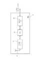
上記の各子機1〜4は、全て同一の構成部材をユニット化したトランシーバタイプのワイヤレス送受信機であり、図4に例示するように、子機1には、上記変位センサ151に接続されてその検出信号を入力するとともに、図示しないボルトなどの固定手段によって取付部14aの底部に固定されるセンサ基板31と、このセンサ基板31の上方に配置されたワイヤレス基板32と、このワイヤレス基板32の上方に配置されたバッテリー電源33とを備えている。また、この子機1では、互いに接離自在なコネクタにて各基板31、32と電源33とが順次接続されるようになっており、当該子機1はビス穴14c内に挿入されるビス(図示せず)によって上記孔131aに装着される蓋14の内部に収納されている。すなわち、センサ基板31及びワイヤレス基板32は、それぞれ設けられた勘合コネクタ31a及び32aとが互いに連結されることでこれらの基板31及び32が電気的に接続され、またワイヤレス基板32及びバッテリー電源33は、それぞれ設けられた勘合コネクタ32b及び33bとが互いに連結されることでこれらの基板32及び電源33が電気的に接続されている。尚、図4では、図面の簡略化のために、上記支持部14bの図示は省略している。また、各基板31及び32は、モールド樹脂によりコーティングされたものであり、これら基板31及び32の回路等の電子部品にグリースや湿気などによる悪影響が極力生じないよう構成されている。 Each of the
また、子機1では、第1及び第2の2つの電源が設けられており、上記バッテリー電源33が一方の電源を構成し、発電手段としてのソーラーパネル40が他方の電源に使用されている。すなわち、子機1では、図5も参照して、ソーラーパネル40は、防振材41を介して密閉部材15の表面に取り付けられており、圧延設備の照明光などの光によって発電し、子機各部への電力供給を行えるようになっている(詳細は後述。)。また、このソーラーパネル40は、バッテリー電源33の補助電源として用いられている。
また、密閉部材15は、上記蓋14に含まれたものであり、当該蓋14内部にバッテリー電源33等を収納した状態で、その取付部14aの開口部側端部に上記ビスにより当該取付部14aとともに上記孔131aに着脱自在に取り付けられる。すなわち、密閉部材15には、取付部14aに形成された例えば4つの上記ビス穴14cに応じて、4つのビス穴15aが設けられており、これらのビス穴14c、15aにビスが挿通され孔131aに固定されると、この密閉部材15が取付部14aの開口部を密閉した状態で当該密閉部材15を含んだ蓋14がベアリングカップ13に取り付けられるよう構成されている。また、この密閉部材15では、一端部側が上記ワイヤレス基板32に接続されたアンテナ39用の円状の溝15b及び貫通孔15cが形成されており、この貫通孔15cを通してアンテナ39は密閉状態の内部から引き出されるとともに、略円状に形成されたアンテナ39の他端部側が溝15bに沿って配置されている。尚、この説明以外に、アンテナ39をベアリングカップ13の外表面に沿わせて配置する構成でもよい。Moreover, in the subunit |
Further, the sealing
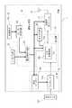
また、子機1では、図6も参照して、変位センサ151からのアナログ式の検出信号を増幅するプリアンプ36a、及びこのプリアンプ36aに順次接続されたPIC(Peripheral Interface Controller)35aと送受信モジュール37とが設けられている。また、PIC 35aには、プリアンプ36aにて増幅された一周期分の検出信号を例えば12ビットの検出データに変換するA/D変換機能35bが付与されている。また、送受信モジュール37は、ワイヤレスチップにより構成されたものであり、親機5からの指示信号を受信する受信手段と、変位センサ151の検出(監視)結果を親機5に送信する送信手段とを一体的に構成したものである。さらに、子機1では、送受信モジュール37で親機5からの指示信号を受信する受信モードと、親機5に対し送受信モジュール37から送信信号を送信する送信モードと、当該子機1が待機状態となるスリープモードとのいずれかのモードが選択可能に構成されており、スリープモードによる間欠運転が行われるようになっている。 Further, in the
また、子機1には、当該子機1の電力源を構成するとともに、バッテリーホルダー33a(図4)に保持された一次電池、例えば二本の単三電池34(図4)を用いた上記バッテリー電源33と、このバッテリー電源33に接続された切替手段としての電源制御回路38aとが設けられている。また、この子機1は、PIC 35aに接続されたタイマー回路35c、プリアンプ36aと電源制御回路38aとの間に設置された電圧レギュレータ36b、及び電源制御回路38aとソーラーパネル40との間に設けられ、蓄電機能がない当該パネル40にて発電された電力を蓄えるコンデンサ充電回路38bを備えている。そして、子機1では、PIC 35a及びタイマ回路35cが変位センサ151の検出信号を処理する処理部35を構成し、さらにはプリアンプ36aと電圧レギュレータ36bとが同検出信号を増幅するアンプ部36を構成して、上記センサ基板31(図4)上に取り付けられている。また、電源制御回路38aとコンデンサ充電回路38bとが子機各部への電力供給を行う電源回路部38を構成し、送受信モジュール37とともに上記ワイヤレス基板32(図4)上に装着されている。さらには、このコンデンサ充電回路38bと上記ソーラーパネル40とにより、バッテリー電源33の補助電源が構成されている。 The
また、子機1では、図6に太線の矢印で示す電力線を介して子機1の各部に対して電力供給を行うように構成されており、後に詳述するように、電源制御回路38aがバッテリー電源33からの電力供給とソーラーパネル40からの電力供給とを切り替えるようになっている。すなわち、PIC 35a、タイマー回路35c、及び受信モジュール37は、同図に示すように、各々電源制御回路38aと直接接続されており、バッテリー電源電圧又はソーラーパネル40で発電された電力を蓄電したコンデンサ充電回路38bからのコンデンサ充電電圧が印加されるようになっている。また、プリアンプ36aでは、その電源電圧として例えば±2.5Vの電圧を印加することが要求されているため、電源制御回路38aからの供給電圧は電圧レギュレータ36bによって上記の電圧に変換された後当該アンプ36aに与えられる。但し、タイマ回路35c以外のPIC 35a、プリアンプ36a、電圧レギュレータ36b、及び送受信モジュール37は、常時、待機(スリープ)状態(つまり、上記スリープモード)に設定されており、子機1では、電源制御回路38aでの切替動作を行わせる点とも相まって、バッテリー電源33の電池34を極力消耗しないようになっている(詳細は後述)。尚、変位センサ151は、電圧レギュレータ36bのオン・オフ状態に連動するプリアンプ36aがオン状態のときに、このプリアンプ36aからケーブルを介して電力の供給を受けており、プリアンプ36aのオン・オフに連動してオン・オフ状態が切り替わる。 Further, the
また、上記PIC 35aは、ワンチップのマイコンにより構成されたものであり、上記プリアンプ36aで信号増幅された変位センサ151の検出信号に対し所定のデータ処理を行う。また、このPIC 35aは、例えば20MHzのクロック周波数にて動作するように構成されたものであり、変位センサ151の検出結果による親機5側での監視精度が低下するのを極力防げるようになっている。具体的にいえば、PIC 35aでは、そのA/D変換機能35bでのサンプリング周波数が例えば3kHzに設定されており、100Hzの高周波信号である変位センサ151の検出信号に対し十分な精度でサンプリング処理を行い、さらに上記送受信モジュール37にてデータ送信するためにPIC 35aはそのサンプリング処理で得られたセンサ検出データを上記高速クロックにてブロック化するようになっている。 The
また、PIC 35aには、そのオン状態の時間を規定する上記タイマ回路35cが接続されており、PIC 35aは、そのオン状態期間において子機各部に対する電力供給のオン/オフ制御を含んだ駆動制御を行うようになっている。つまり、このタイマ回路35cは、所定の周期(例えば、10sec)毎に、PIC 35aを起動させる起動信号を当該PIC 35aに出力するように構成されており、PIC 35aでは、起動信号が入力されると、待機状態からオン状態に切り替えられ、さらにオン状態に切り替えられた時点から所定時間(例えば、10msec)の間オン状態を継続する。そして、PIC 35aは、オン状態になると、送受信モジュール37に対して、スリープ状態からオン状態に切り替えるON信号を直ちに出力し、電源制御回路38aからの電力供給を許容するとともに、送受信モジュール37を受信モードにして、子機1でのモードをもスリープモードから受信モードに移行させる。 The
また、PIC 35aは、上記所定時間のオン状態期間に、送受信モジュール37が親機5からの送信波を受信すると、その送信波に含まれた親機5からの指示信号の内容を判別する判別処理を行う。そして、PIC 35aは、受信した指示信号に変位センサ151の検出結果を要求する要求信号が含まれていることを検知したときのみ、PIC 35aは電圧レギュレータ36bに対しスリープ状態からオン状態に切り換えるON信号を出力して、プリアンプ36aから変位センサ151への電力供給を許容する。また、PIC 35aは、送受信モジュール37を送信モードにして、子機1でのモードを受信モードから送信モードに移行させるとともに、PIC 35aは、そのA/D変換機能35bを起動する。これにより、PIC 35aは、変位センサ151からのセンサ検出信号をデータ処理してセンサ検出データを取得し、この取得したデータを送受信モジュール37を介して親機5に発信する。 Further, when the transmission /
また、親機5から受信した指示信号に上記要求信号が含まれていなければ、PIC 35aは、当該指示信号に応じた処理を行うようになっている。
また、PIC 35aは、親機5からの指示信号が入力されずに、上記オン状態期間が経過すると、送受信モジュール37に対し、オン状態からスリープ状態に切り替えるOFF信号を出力することで電源制御回路38aから送受信モジュール37への電力供給を遮断して、当該送受信モジュール37を動作不能状態のスリープモードする。さらには、PIC 35a自体も、A/D変換機能35bを停止させてオン状態からスリープ状態に移行し、子機1では、受信モードからスリープモードに移行される。If the instruction signal received from the
In addition, the
また、PIC 35a等の上記子機各部でのスリープ状態は、消費電流が0.1mA以下であるスリープ状態であり、上記のように、タイマ回路35cがPIC 35aを起動し、PIC 35aが子機各部を起動することにより、子機1では、バッテリー電源33の消費電力量を極力抑えるように構成されている。つまり、子機1のスリープモードでは、その接続された変位センサ151を含め、消費電力量が極めて少ないICからなる上記タイマ回路35cのみが常時、動作するようになっており、PIC 35aが親機5からの上記要求信号を確認したときのみ、バッテリー電源33が使用されて変位センサ151のセンサ検出データが親機5に伝達される。しかも、ソーラーパネル40によって発電された電力がコンデンサ充電回路38bに所定電力量以上に蓄積されている場合では、電源制御回路38aはバッテリー電源33からの電力供給からコンデンサ充電回路38bからの電力供給に切り替える。これにより、バッテリー電源33の電池34が消耗するのを極力抑制することができ、バッテリー電源33の電池寿命を延ばしてその交換時期を長くすることが可能となる。 The sleep state in each part of the slave unit such as the
また、PIC 35aには、バッテリー電源33の電池容量の残量を検出する機能がソフトウェアによって付与されており、現時点でのバッテリー電源33の電圧を検出するように構成されている。この電池残量検出処理は、PIC 35aが上記要求信号を受信し、かつ電源制御回路38aを介してバッテリー電源33から電力供給を受けているときに実施されるようになっており、PIC 35aは、上記センサ検出データとともに、検出した電池残量(検出電圧)データを親機5に送信させる。また、PIC 35aでは、現時点でのバッテリー電源電圧が所定電圧以下であることを判別したときには、PIC 35aは親機5に対しバッテリー電源33の電池34を交換することを要求する電池交換信号を生成して、上記電池残量データに含めて送信させるよう構成されている。
尚、上記の説明以外に、親機5が電池残量検出処理だけを単独で実施させる指示信号を子機1に送信し、その処理結果のみを親機5に返信させることもできる。このような変位センサ151の検出信号を処理しない場合には、PIC 35aは、電源制御回路38a(バッテリー電源33)からプリアンプ36aへの電力供給を許容するオン信号を出力せずに当該プリアンプ36aを動作不能状態で維持し電池消耗を極力抑えるようになっている。The
In addition to the above description, it is also possible for the
上記送受信モジュール37には、所定周波数の送信波(搬送波)を発振する発振器、センサ検出データを送信波に乗せるための変調を行う変調器、及び親機5からの送信波を復調する復調器が設けられており、接続されたアンテナ39を介して親機5と双方向の無線通信を行う。また、送受信モジュール37は、PIC 35aからの指示信号に従って送信モード又は受信モードを択一的に選択するよう構成されており、1送信サイクル(上記搬送波の1周期)毎に、所定のビット数のデータブロックをシリアル伝送方式にて送信するようになっている。
上記電源制御回路38aは、マルチプレクサ等のアナログスイッチを用いて構成されたものであり、バッテリー電源33から常時電圧が印加されている。また、この電源制御回路38aには、例えば電気二重層キャパシタを含んで構成された上記コンデンサ充電回路38bからも常時電圧が印加されており、当該制御回路38aでは、バッテリー電源33よりもコンデンサ充電回路38bを優先するように構成されている。すなわち、電源制御回路38aでは、コンデンサ充電回路38bからの印加電圧が所定の電圧値以上のときに、ソーラーパネル40によって発電された電力が当該充電回路38bで所定電力量以上蓄積されていると判断される。そして、電源制御回路38aは、子機各部への電力供給経路をバッテリー電源33からコンデンサ充電回路38bに自動的に切り替えて、バッテリー電源33の電池消耗を極力低減する。The transmission /
The power
上記親機5には、図7に示すように、子機1〜4の各送受信モジュール37との間で共通の周波数を用いて無線通信を行う送受信モジュール51と、当該親機各部の制御を行う制御部を構成するPIC 52と、パネルコンピュータ7(図3)に接続されたRS232Cドライバ53とが設けられている。また、親機5は、子機1〜4と同様に、トランシーバタイプのワイヤレス送受信機を構成しており、その電力源としてのバッテリー電源などが含まれている。このバッテリー電源電圧は、子機1〜4と同様に、PIC 52に設けられた検出機能によって常時監視されており、その検出電圧値(現時点でのバッテリー電源電圧値)がパネルコンピュータ7側に通知されるとともに、検出電圧値が所定電圧以下に低下した時点で電池交換信号が同コンピュータ7側に出力される。また、送受信モジュール51は、上記送受信モジュール37と同様に、発振器、変調器、及び復調器を備えたものであり、PIC 52からの指示信号に従って送信モード又は受信モードを択一的に選択するとともに、1送信サイクル毎に、所定のビット数のデータブロックをアンテナ50から発信するよう構成されている。 As shown in FIG. 7, the
また、親機5は、パネルコンピュータ7側からの指示(リクエスト信号)に従って、各子機1〜4に対応するセンサの検出データを送信することを要求するとともに、各子機1〜4から受信したセンサ検出データ及び電池残量データをパネルコンピュータ7側に転送する。さらに、親機5は、一つの子機に対してその子機に接続されたセンサの検出データの送信を要求するときに、当該子機の識別子を含んだ要求信号を作成し、この作成した信号を含むデータブロックを発信するようになっている。
上記パネルコンピュータ7には、そのコンピュータ機能として、上記変位センサ151〜154からのセンサ検出データに基づいた対応する軸12a(駆動軸10)での損傷の程度(進行度合い)についての判別・診断機能が付与されている。また、このコンピュータ7には、各検出データの波形や上記進行度合いの変化等の所定の履歴情報をディスプレイに表示するモニタリング機能、各センサへのセンシングの開始や子機1〜4及び親機5の各バッテリー電源での電池残量の確認等を行わせる動作指示機能がソフトウェアにて与えられている。
また、PC 8には、パネルコンピュータ7が有する上記のコンピュータ機能に加えて、入力した検出データやそれに基づく損傷の診断結果などのデータを保存したり、他の情報処理端末21に上記の保存データを提供するWebサーバとして働いたりするようなサーバ機能が付与されている。In addition, according to an instruction (request signal) from the panel computer 7 side, the
The panel computer 7 has, as its computer function, a discrimination / diagnosis function for the degree of damage (advance level) on the
Further, in addition to the above-described computer functions of the panel computer 7, the PC 8 stores input detection data and data such as damage diagnosis results based on the data, or stores the stored data in another
以上のように構成された本実施形態では、各子機(ワイヤレスユニット)1〜4において、ソーラーパネル(発電手段)40を設けて、このソーラーパネル40をバッテリー電源33の補助電源に用いているので、当該バッテリー電源33の単三電池(一次電池)34が消耗するのを低減することができる。この結果、上記従来例と異なり、バッテリー電源33の長寿命化を図ることができる。しかも、本実施形態では、電源制御回路(切替手段)38aにより、バッテリー電源33からの電力供給よりもコンデンサ充電回路(補助電源)38bからの電力供給を優先的に行わせているので、バッテリー電源33の電池消耗をより確実に低減して、その長寿命化を容易に行うことが可能となる。また、このように、バッテリー電源33の長寿命化を図ることができるので、その電池交換作業の頻度が少なく長期間のメンテナンスフリー性を有する駆動軸監視システムを容易に構築することができる。 In the present embodiment configured as described above, a solar panel (power generation means) 40 is provided in each of the slave units (wireless units) 1 to 4, and this
また、本実施形態では、バッテリー電源33及び送受信モジュール(送信手段)37がベアリングカップ13に形成されたグリース注入用の孔131aの内部に配置され、ソーラーパネル40が蓋14の密閉部材15表面上に取り付けられているので、圧延設備などのように十字軸継手の十字軸が外部にほとんど露出されない駆動軸に用いるときでも、バッテリー電源33の電池消耗を低減した子機を容易に取り付けることができる。この結果、センサの設置箇所を確保し難く、かつ回転動作する駆動軸に対して、その損傷の程度(進行度合い)を正確に把握することができ、十字軸継手等の交換作業が必要な時期を正確に判断することが可能となる。
また、本実施形態では、ベアリングカップ13に対し着脱可能な蓋14にセンサに接続された子機を取付・取外し可能に取り付けているので、既設の駆動軸に対しても、センサ及びその検出データを送信する子機を容易に設置することが可能となり、損傷の進行度合いを監視できなかった駆動軸に対しても、長寿命なバッテリー電源を有する子機により、その監視を行うことができる。しかも、蓋14をベアリングカップ13から取り外すことにより、十字軸継手11等の分解作業を実施することなく、これらセンサ及び子機の交換作業を容易に行うことができる。In the present embodiment, the
Moreover, in this embodiment, since the subunit | mobile_unit connected to the sensor is attached to the
[実施形態2]
図8は、別の実施形態に係る子機及びベアリングカップグリース注入孔用蓋の要部構成例を示す図である。図において、本実施形態と上記実施形態との主な相違点は、ソーラーパネルに代えて、発電手段に圧電素子及び球を設けた点である。
図8において、本実施形態では、密閉部材25の表面上に、圧電セラミックス等により構成された圧電素子42aが取り付けられている。また、上記密閉部材25は、図9も参照して、互いに分離可能に構成された蓋部材25aと有底状の筒部材25bとにより構成されている。これら蓋部材25a及び筒部材25bには、上記取付部14aのビス穴14cに応じて形成されたビス穴25a1及び25b1がそれぞれ設けられており、上記密閉部材15と同様に、ビスによって当該蓋部材25a及び筒部材25bがベアリングカップ13に着脱可能に取り付けられる。また、蓋部材25aの上面側には、上記アンテナ39の略円状部分が配置される溝25a2が形成されている。さらに、蓋部材25a及び筒部材25bには、アンテナ39が挿通される貫通孔25a3及び25b4がそれぞれ設けられている。[Embodiment 2]
FIG. 8 is a view showing a configuration example of a main part of a slave unit and a bearing cup grease injection hole lid according to another embodiment. In the figure, the main difference between this embodiment and the above embodiment is that a power generation means is provided with a piezoelectric element and a sphere instead of a solar panel.
In FIG. 8, in the present embodiment, a
また、上記蓋部材25aでは、その上側表面に取り付けられた上記圧電素子42aに加えて、下側表面にも圧電素子42bが設置されている。
また、上記筒部材25bでは、その内部が壁25b2によって矩形状に仕切られており、さらにこの壁25b2にて仕切られた矩形状空間は図の上下左右方向に設けられた小壁25b3により、例えば8つの小区画に区切られている。そして、各区画には、上記駆動軸10の回転動作に応じて移動可能な動作体としての球43が配置されている。これらの各球43は、例えば鉄により構成されたものであり、上記の回転動作に応動して図9(c)の上下方向に移動し、上記圧電素子42bに衝突するようになっている。In the
Further, in the
上記圧電素子42a、42bは、図10も参照して、コンデンサ充電回路38bに接続されており、駆動軸10の回転動作に応じて歪むことにより発電して、その発電した電力を当該充電回路38bに蓄電するよう構成されている。つまり、駆動軸10が回転動作したときに、その回転動作に応動して、球43が圧電素子42bに衝突し、これにより当該圧電素子42bに歪みが発生する。そして、この発生した歪みによって電力が生じてコンデンサ充電回路38bをチャージする。また、球43と圧電素子42bとの衝突によって生じる衝撃は、蓋部材25aを介して圧電素子42aに伝えられて、当該圧電素子42aにも歪みが生じ電力を発生してコンデンサ充電回路38bをチャージする。尚、蓋部材25aの厚みは、この部材25aの材質にも異なるが、10mm程度以下の薄いものを使用することが上記衝撃による圧電素子42aでの歪みを大きくして効率よく発電できる点で好ましい。
以上のように、本実施形態では、圧電素子(発電手段)42a、42bが、駆動軸10の回転動作に応動して発電するので、上記実施形態1と同様に、バッテリー電源33の電池消耗を低減することができ、当該バッテリー電源33を長寿命化を図ることができる。また、圧電素子42a、42b及び球43(発電手段)を蓋14の密閉部材25に取り付けているので、バッテリー電源33の電池消耗を低減した子機を構成して、実施形態1と同様な効果を奏することができる。The
As described above, in the present embodiment, since the piezoelectric elements (power generation means) 42a and 42b generate power in response to the rotation operation of the
尚、上記の説明では、ソーラーパネル(太陽電池)や圧電素子からなる発電手段を、一次電池を用いたバッテリー電源の補助電源とした構成について説明したが、本発明のワイヤレスユニットは、バッテリー電源と、発電手段と、駆動軸の損傷を検出するためのセンサに接続されてそのセンサからの検出データを送信する送信手段とを備えたものであれば何等限定されない。具体的には、バッテリー電源に鉛蓄電池などの二次電池を用いるとともに、発電手段にて発電した電力を二次電池に逐次充電する構成でもよい。また、上記アンテナに接続されたコイルと、このコイルとともにLC共振回路を構成するキャパシタとを用いて、発電手段を構成して、アンテナが所定(共振)周波数の電波を受信することにより、LC共振回路が発電しキャパシタにチャージする構成でもよい。また、発電手段が発電した電力を電気二重層キャパシタ以外の蓄電池等の他の蓄電部材に蓄える構成でもよい。 In the above description, the power generation means including a solar panel (solar cell) or a piezoelectric element has been described as an auxiliary power source for a battery power source using a primary battery. However, the wireless unit of the present invention includes a battery power source and a power source. The power generation means and the transmission means connected to a sensor for detecting damage to the drive shaft and transmitting detection data from the sensor are not limited at all. Specifically, a secondary battery such as a lead storage battery may be used as the battery power source, and the power generated by the power generation means may be sequentially charged to the secondary battery. In addition, a coil connected to the antenna and a capacitor that constitutes an LC resonance circuit together with the coil constitute a power generation means, and the antenna receives a radio wave of a predetermined (resonance) frequency, whereby LC resonance The circuit may generate electricity and charge the capacitor. Moreover, the structure which stores the electric power which the electric power generation means generated in other electrical storage members, such as storage batteries other than an electric double layer capacitor, may be sufficient.
また、上記の説明では、1個のワイヤレスユニットに直結された1個の変位センサを用いた場合について説明したが、本発明はこれに限定されるものではなく、ワイヤレスユニットやセンサの設置数あるいはセンサ種類(形式)などは上記のものに何等限定されない。つまり、センサは、駆動軸の損傷(軸での表面剥離)に起因して変化する物理量を検出するものであればよく、例えば振動センサを十字軸の中央部に対向配置して当該十字軸の振動を検出する構成でもよい。また、力や温度、あるいは上記剥離に応じて増加するグリース内の鉄粉濃度等の検出データを取得するものでもよい。また、複数のセンサを1個のワイヤレスユニットに接続して、このユニットからセンサ毎にその検出データを発信させるものでもよい。 In the above description, the case where one displacement sensor directly connected to one wireless unit is used has been described. However, the present invention is not limited to this, and the number of wireless units and sensors installed or The sensor type (form) is not limited to the above. In other words, the sensor only needs to detect a physical quantity that changes due to damage to the drive shaft (surface peeling on the shaft). For example, a vibration sensor is disposed opposite to the center of the cross shaft and It may be configured to detect vibration. Further, detection data such as force, temperature, or iron powder concentration in grease that increases in accordance with the above-described peeling may be acquired. Further, a plurality of sensors may be connected to one wireless unit, and detection data may be transmitted from this unit for each sensor.
また、上記の説明では、バッテリー電源やセンサ基板などをグリース注入用孔の内部に配置した場合について説明したが、本発明はこれに限定されるものではなく、駆動軸の動作を阻害しない場合ではベアリングカップ外側にバッテリー電源等を取り付けてもよい。また、例えばベアリングカップ表面に凹部等を設け、バッテリー電源等を当該カップ内側に配置するものでもよい。但し、上記のように、ベアリングカップに形成されたグリース注入用孔内部にバッテリー電源等を配置する場合の方が、当該ユニットを簡単、かつコスト安価に取り付けることができる点で好ましい。
また、上記の説明では、バッテリーホルダー、ワイヤレス基板、及びセンサ基板を上下三段にしたワイヤレスユニットについて説明したが、例えば一つの基板上に、バッテリーホルダーなどのユニット構成部材を配置するものでもよい。In the above description, the case where the battery power source, the sensor substrate, etc. are arranged inside the grease injection hole has been described. However, the present invention is not limited to this, and the case where the operation of the drive shaft is not hindered. A battery power source or the like may be attached outside the bearing cup. Further, for example, a concave portion or the like may be provided on the surface of the bearing cup, and a battery power source or the like may be disposed inside the cup. However, as described above, the case where the battery power source or the like is disposed inside the grease injection hole formed in the bearing cup is preferable in that the unit can be attached easily and at a low cost.
In the above description, the wireless unit in which the battery holder, the wireless substrate, and the sensor substrate are arranged in three upper and lower stages has been described. However, for example, a unit component such as a battery holder may be disposed on one substrate.
また、上記実施形態1の説明では、蓋の密閉部材の表面上にソーラーパネルを設置した構成について説明したが、ベアリングカップの外表面や駆動軸の各軸部の外周面上などの駆動軸表面上にソーラーパネルを設けてもよい。但し、上記のように、防振材を介在させて、上記駆動軸表面上にソーラーパネルを設置する場合の方が、駆動軸の回転動作に伴って発生する振動等の衝撃でソーラーパネルが破損するのを防止できる点で好ましい。 In the description of the first embodiment, the configuration in which the solar panel is installed on the surface of the lid sealing member has been described. However, the driving shaft surface such as the outer surface of the bearing cup or the outer peripheral surface of each shaft portion of the driving shaft. A solar panel may be provided on the top. However, as described above, when installing a solar panel on the surface of the drive shaft with an anti-vibration material interposed between them, the solar panel is damaged by the impact of vibration generated by the rotation of the drive shaft. It is preferable in that it can be prevented.
また、上記実施形態2の説明では、圧電素子及び球(動作体)を有する発電手段について説明したが、本発明はこれに限定されるものではなく、駆動軸の回転動作に伴って生じる当該駆動軸での運動エネルギーを電気エネルギーに変換することにより、駆動軸の動作時に自動的に発電するものであれば何等限定されない。具体的には、上記蓋部材の内面にソレノイドコイルを配置するとともに、一端部が上記筒部材の底側に固定された弾性バネの他端側に永久磁石を取り付ける。そして、弾性バネが駆動軸の回転動作に応動して伸縮運動することにより、ソレノイドコイルを通る永久磁石からの磁界を変動させて、当該コイルに電圧を誘起させ電力を発生させる構成でもよい。また、球を設けることなく、矩形状の上記圧電素子の一辺側のみを上記密閉部材の表面に固定し、この圧電素子の他辺(対向辺)側が駆動軸の回転動作に応動して振動することにて歪みを発生し発電する構成でもよい。但し、上記のように、駆動軸の回転動作に応動して圧電素子に衝突する上記球を用いる場合の方が、当該圧電素子を大きく歪ませて効率よく電力を発生させることができ、バッテリー電源の電池消耗をより低減することができる点で好ましい。 In the description of the second embodiment, the power generation means including the piezoelectric element and the sphere (operation body) has been described. However, the present invention is not limited to this, and the driving that occurs in association with the rotation operation of the drive shaft. There is no limitation as long as it automatically generates electric power during the operation of the drive shaft by converting kinetic energy on the shaft into electric energy. Specifically, a solenoid coil is disposed on the inner surface of the lid member, and a permanent magnet is attached to the other end side of the elastic spring whose one end is fixed to the bottom side of the cylindrical member. The elastic spring may be expanded and contracted in response to the rotation operation of the drive shaft, thereby changing the magnetic field from the permanent magnet passing through the solenoid coil to induce voltage in the coil and generate electric power. Further, without providing a sphere, only one side of the rectangular piezoelectric element is fixed to the surface of the sealing member, and the other side (opposite side) of the piezoelectric element vibrates in response to the rotation of the drive shaft. In particular, it may be configured to generate distortion and generate power. However, as described above, in the case of using the sphere that collides with the piezoelectric element in response to the rotational movement of the drive shaft, the piezoelectric element can be greatly distorted to generate electric power efficiently. It is preferable in that battery consumption can be further reduced.
1〜4 子機(ワイヤレスユニット)
5 親機
10 駆動軸
11 十字軸継手
13 ベアリングカップ
131a グリース注入用の孔
14 (ベアリングカップグリース注入孔用)蓋
15、25 密閉部材
33 バッテリー電源
34 単三電池(一次電池)
37 送受信モジュール(送信手段)
38a 電源制御回路(切替手段)
38b コンデンサ充電回路(補助電源)
40 ソーラーパネル(発電手段、補助電源)
41 防振材
42a、42b 圧電素子(発電手段、補助電源)
43 球(発電手段、動作体)
151〜154 変位センサ
T 駆動軸監視システム1-4 Slave unit (wireless unit)
5
37 Transmission / reception module (transmission means)
38a Power supply control circuit (switching means)
38b Capacitor charging circuit (auxiliary power supply)
40 Solar panels (power generation means, auxiliary power supply)
41
43 balls (power generation means, operating body)
151-154 Displacement sensor T Drive shaft monitoring system
Claims (11)
Translated fromJapanese発電手段と、
前記駆動軸の損傷を検出するためのセンサに接続されてそのセンサからの検出データを送信する送信手段と
を備えたことを特徴とする駆動軸用ワイヤレスユニット。A wireless unit having a battery power source and attached to a drive shaft,
Power generation means;
A drive shaft wireless unit, comprising: a transmission unit connected to a sensor for detecting damage to the drive shaft and transmitting detection data from the sensor.
前記発電手段が、前記バッテリー電源の補助電源に使用され、かつ、この補助電源からの電力供給と前記一次電池からの電力供給とを切り替える切替手段を設けたことを特徴とする請求項1に記載の駆動軸用ワイヤレスユニット。The battery power source is configured using a primary battery,
The power generation means is used as an auxiliary power source for the battery power source, and switching means for switching between power supply from the auxiliary power source and power supply from the primary battery is provided. Wireless unit for drive shaft.
前記バッテリー電源及び前記送信手段が、前記ベアリングカップに形成されたグリース注入用の孔の内部に配置され、
前記ソーラーパネルが、前記ベアリングカップの表面に取り付けられていることを特徴とする請求項3に記載の駆動軸用ワイヤレスユニット。The drive shaft includes a cross joint having a bearing cup,
The battery power source and the transmitting means are disposed inside a grease filling hole formed in the bearing cup,
The wireless unit for drive shaft according to claim 3, wherein the solar panel is attached to a surface of the bearing cup.
前記バッテリー電源及び前記送信手段が、前記ベアリングカップに形成されたグリース注入用の孔の内部に配置され、
前記圧電素子が、前記ベアリングカップに取り付けられていることを特徴とする請求項8に記載の駆動軸用ワイヤレスユニット。The drive shaft includes a cross joint having a bearing cup,
The battery power source and the transmitting means are disposed inside a grease filling hole formed in the bearing cup,
The wireless unit for a drive shaft according to claim 8, wherein the piezoelectric element is attached to the bearing cup.
バッテリー電源と、発電手段と、前記駆動軸の損傷を検出するためのセンサに接続されてそのセンサからの検出データを送信する送信手段とを備えるワイヤレスユニットが装着されていることを特徴とするベアリングカップグリース注入孔用蓋。In a drive shaft provided with a cross shaft joint, a lid attached to a hole for grease injection formed in a bearing cup of the cross shaft joint,
A bearing equipped with a wireless unit comprising a battery power source, power generation means, and transmission means connected to a sensor for detecting damage to the drive shaft and transmitting detection data from the sensor. Cup grease injection hole lid.
前記子機に、請求項1〜9のいずれかに記載の駆動軸用ワイヤレスユニットを使用したことを特徴とする駆動軸監視システム。A monitoring system that has a slave unit provided on the drive shaft side and a master unit capable of wireless communication with the slave unit, and monitors the drive shaft based on a transmission signal from the slave unit;
A drive shaft monitoring system using the drive shaft wireless unit according to claim 1 for the slave unit.
Priority Applications (1)
| Application Number | Priority Date | Filing Date | Title |
|---|---|---|---|
| JP2004289606AJP2006106917A (en) | 2004-10-01 | 2004-10-01 | Wireless unit for drive shaft, lid for bearing cup grease injection hole, and drive shaft monitoring system |
Applications Claiming Priority (1)
| Application Number | Priority Date | Filing Date | Title |
|---|---|---|---|
| JP2004289606AJP2006106917A (en) | 2004-10-01 | 2004-10-01 | Wireless unit for drive shaft, lid for bearing cup grease injection hole, and drive shaft monitoring system |
Publications (1)
| Publication Number | Publication Date |
|---|---|
| JP2006106917Atrue JP2006106917A (en) | 2006-04-20 |
Family
ID=36376617
Family Applications (1)
| Application Number | Title | Priority Date | Filing Date |
|---|---|---|---|
| JP2004289606AWithdrawnJP2006106917A (en) | 2004-10-01 | 2004-10-01 | Wireless unit for drive shaft, lid for bearing cup grease injection hole, and drive shaft monitoring system |
Country Status (1)
| Country | Link |
|---|---|
| JP (1) | JP2006106917A (en) |
Cited By (11)
| Publication number | Priority date | Publication date | Assignee | Title |
|---|---|---|---|---|
| JP2009008616A (en)* | 2007-06-29 | 2009-01-15 | Jtekt Corp | Drive shaft damage diagnosis unit and drive shaft monitoring system |
| JP2010180917A (en)* | 2009-02-04 | 2010-08-19 | Jtekt Corp | Drive shaft monitoring system |
| JP2014195230A (en)* | 2013-03-29 | 2014-10-09 | Mitsubishi Electric Corp | Radio communication device |
| JP2016130577A (en)* | 2015-01-15 | 2016-07-21 | 日本精工株式会社 | Bearing with wireless sensor |
| JP2016157356A (en)* | 2015-02-26 | 2016-09-01 | 一般財団法人マイクロマシンセンター | Wireless sensor terminal |
| CN107851371A (en)* | 2015-10-08 | 2018-03-27 | 川崎重工业株式会社 | The temperature sensor unit with radio communication function of railcar bogie |
| CN108974706A (en)* | 2017-06-02 | 2018-12-11 | 上海三思电子工程有限公司 | Monitor accessory, communal facility and urban facilities communication system |
| JP2020144608A (en)* | 2019-03-06 | 2020-09-10 | 株式会社Ihi | Telemeter device and telemeter system |
| CN113785142A (en)* | 2019-05-02 | 2021-12-10 | 邦迪奥利及帕维西股份公司 | System for checking the use of a cardan shaft of a tool connected to a motor and cardan shaft provided with such a system |
| EP3933222A1 (en)* | 2020-06-30 | 2022-01-05 | Off-Highway Powertrain Services Germany GmbH | Shaft with integrated generator |
| CN117419269A (en)* | 2023-11-06 | 2024-01-19 | 宁波东佳汽车零部件有限公司 | Bearing oiling detects all-in-one |
- 2004
- 2004-10-01JPJP2004289606Apatent/JP2006106917A/ennot_activeWithdrawn
Cited By (14)
| Publication number | Priority date | Publication date | Assignee | Title |
|---|---|---|---|---|
| JP2009008616A (en)* | 2007-06-29 | 2009-01-15 | Jtekt Corp | Drive shaft damage diagnosis unit and drive shaft monitoring system |
| JP2010180917A (en)* | 2009-02-04 | 2010-08-19 | Jtekt Corp | Drive shaft monitoring system |
| JP2014195230A (en)* | 2013-03-29 | 2014-10-09 | Mitsubishi Electric Corp | Radio communication device |
| JP2016130577A (en)* | 2015-01-15 | 2016-07-21 | 日本精工株式会社 | Bearing with wireless sensor |
| JP2016157356A (en)* | 2015-02-26 | 2016-09-01 | 一般財団法人マイクロマシンセンター | Wireless sensor terminal |
| CN107851371B (en)* | 2015-10-08 | 2020-04-07 | 川崎重工业株式会社 | Temperature sensor unit with wireless communication function for railway vehicle bogie |
| CN107851371A (en)* | 2015-10-08 | 2018-03-27 | 川崎重工业株式会社 | The temperature sensor unit with radio communication function of railcar bogie |
| CN108974706A (en)* | 2017-06-02 | 2018-12-11 | 上海三思电子工程有限公司 | Monitor accessory, communal facility and urban facilities communication system |
| JP2020144608A (en)* | 2019-03-06 | 2020-09-10 | 株式会社Ihi | Telemeter device and telemeter system |
| JP7207021B2 (en) | 2019-03-06 | 2023-01-18 | 株式会社Ihi | Telemetry system |
| CN113785142A (en)* | 2019-05-02 | 2021-12-10 | 邦迪奥利及帕维西股份公司 | System for checking the use of a cardan shaft of a tool connected to a motor and cardan shaft provided with such a system |
| EP3933222A1 (en)* | 2020-06-30 | 2022-01-05 | Off-Highway Powertrain Services Germany GmbH | Shaft with integrated generator |
| US12015325B2 (en) | 2020-06-30 | 2024-06-18 | Off-Highway Powertrain Services Germany GmbH | Universal shaft with a generator for generating electricity |
| CN117419269A (en)* | 2023-11-06 | 2024-01-19 | 宁波东佳汽车零部件有限公司 | Bearing oiling detects all-in-one |
Similar Documents
| Publication | Publication Date | Title |
|---|---|---|
| JP2006106917A (en) | Wireless unit for drive shaft, lid for bearing cup grease injection hole, and drive shaft monitoring system | |
| CN102645292B (en) | Piezoelectric vibration type force sensor and robot apparatus | |
| CN103887891B (en) | The control appliance of machinery | |
| CN102077054A (en) | Microgyroscope | |
| JP2008171403A (en) | Wireless output sensor, proximity sensor, working apparatus and control system | |
| JP2013057659A (en) | Module for monitoring at least one characteristic physical amount of state of contact guide member | |
| RU2526864C2 (en) | Bearing current sensing device with energy converter | |
| JP7331108B2 (en) | Sensor system and wireless communication equipment | |
| JP4198817B2 (en) | Tire internal condition measuring instrument | |
| JP2016148628A (en) | Wireless sensor, monitoring system and monitoring method using the same | |
| JP2017134011A (en) | Wearable apparatus and communication system | |
| JP2013124874A (en) | Rotation sensor | |
| US7583254B2 (en) | Input device including power generating device | |
| JP2017007029A (en) | Rotary tool, processing state monitor and machine tool | |
| WO2005111451A1 (en) | Shaft joint monitoring device | |
| JP6524667B2 (en) | Wireless sensor bearing | |
| JP2020139752A (en) | Vibration sensor | |
| JP2017187380A (en) | Sensor module and wireless sensor device | |
| JP4599889B2 (en) | Shaft coupling monitoring device | |
| US10302138B2 (en) | Sensor arrangement and rolling bearing having such a sensor arrangement | |
| JP2007164811A (en) | Wireless sensor | |
| JP2014516434A (en) | Measuring device with transmitter circuit for wireless transmission of measured values | |
| US20080231250A1 (en) | Method and Assembly For Supplying Power to an Active Independent Component | |
| CN212543617U (en) | Rotatable device | |
| JP2006099396A (en) | Wireless unit and monitoring system for steel facilities using the same |
Legal Events
| Date | Code | Title | Description |
|---|---|---|---|
| A621 | Written request for application examination | Free format text:JAPANESE INTERMEDIATE CODE: A621 Effective date:20070924 | |
| A761 | Written withdrawal of application | Free format text:JAPANESE INTERMEDIATE CODE: A761 Effective date:20100820 |