JP2006106897A - Reader / writer and RFID system - Google Patents
Reader / writer and RFID systemDownload PDFInfo
- Publication number
- JP2006106897A JP2006106897AJP2004289289AJP2004289289AJP2006106897AJP 2006106897 AJP2006106897 AJP 2006106897AJP 2004289289 AJP2004289289 AJP 2004289289AJP 2004289289 AJP2004289289 AJP 2004289289AJP 2006106897 AJP2006106897 AJP 2006106897A
- Authority
- JP
- Japan
- Prior art keywords
- tag
- reader
- writer
- antenna
- information
- Prior art date
- Legal status (The legal status is an assumption and is not a legal conclusion. Google has not performed a legal analysis and makes no representation as to the accuracy of the status listed.)
- Withdrawn
Links
Images


Classifications
- H—ELECTRICITY
- H01—ELECTRIC ELEMENTS
- H01Q—ANTENNAS, i.e. RADIO AERIALS
- H01Q21/00—Antenna arrays or systems
- H01Q21/28—Combinations of substantially independent non-interacting antenna units or systems
- A—HUMAN NECESSITIES
- A01—AGRICULTURE; FORESTRY; ANIMAL HUSBANDRY; HUNTING; TRAPPING; FISHING
- A01K—ANIMAL HUSBANDRY; AVICULTURE; APICULTURE; PISCICULTURE; FISHING; REARING OR BREEDING ANIMALS, NOT OTHERWISE PROVIDED FOR; NEW BREEDS OF ANIMALS
- A01K69/00—Stationary catching devices
- A01K69/06—Traps
- A01K69/10—Collapsible traps
- G—PHYSICS
- G06—COMPUTING OR CALCULATING; COUNTING
- G06K—GRAPHICAL DATA READING; PRESENTATION OF DATA; RECORD CARRIERS; HANDLING RECORD CARRIERS
- G06K7/00—Methods or arrangements for sensing record carriers, e.g. for reading patterns
- G06K7/10—Methods or arrangements for sensing record carriers, e.g. for reading patterns by electromagnetic radiation, e.g. optical sensing; by corpuscular radiation
- G06K7/10009—Methods or arrangements for sensing record carriers, e.g. for reading patterns by electromagnetic radiation, e.g. optical sensing; by corpuscular radiation sensing by radiation using wavelengths larger than 0.1 mm, e.g. radio-waves or microwaves
- G06K7/10019—Methods or arrangements for sensing record carriers, e.g. for reading patterns by electromagnetic radiation, e.g. optical sensing; by corpuscular radiation sensing by radiation using wavelengths larger than 0.1 mm, e.g. radio-waves or microwaves resolving collision on the communication channels between simultaneously or concurrently interrogated record carriers.
- G06K7/10069—Methods or arrangements for sensing record carriers, e.g. for reading patterns by electromagnetic radiation, e.g. optical sensing; by corpuscular radiation sensing by radiation using wavelengths larger than 0.1 mm, e.g. radio-waves or microwaves resolving collision on the communication channels between simultaneously or concurrently interrogated record carriers. the collision being resolved in the frequency domain, e.g. by hopping from one frequency to the other
- G—PHYSICS
- G06—COMPUTING OR CALCULATING; COUNTING
- G06K—GRAPHICAL DATA READING; PRESENTATION OF DATA; RECORD CARRIERS; HANDLING RECORD CARRIERS
- G06K7/00—Methods or arrangements for sensing record carriers, e.g. for reading patterns
- G06K7/10—Methods or arrangements for sensing record carriers, e.g. for reading patterns by electromagnetic radiation, e.g. optical sensing; by corpuscular radiation
- G06K7/10009—Methods or arrangements for sensing record carriers, e.g. for reading patterns by electromagnetic radiation, e.g. optical sensing; by corpuscular radiation sensing by radiation using wavelengths larger than 0.1 mm, e.g. radio-waves or microwaves
- G06K7/10019—Methods or arrangements for sensing record carriers, e.g. for reading patterns by electromagnetic radiation, e.g. optical sensing; by corpuscular radiation sensing by radiation using wavelengths larger than 0.1 mm, e.g. radio-waves or microwaves resolving collision on the communication channels between simultaneously or concurrently interrogated record carriers.
- G06K7/10079—Methods or arrangements for sensing record carriers, e.g. for reading patterns by electromagnetic radiation, e.g. optical sensing; by corpuscular radiation sensing by radiation using wavelengths larger than 0.1 mm, e.g. radio-waves or microwaves resolving collision on the communication channels between simultaneously or concurrently interrogated record carriers. the collision being resolved in the spatial domain, e.g. temporary shields for blindfolding the interrogator in specific directions
- G—PHYSICS
- G06—COMPUTING OR CALCULATING; COUNTING
- G06K—GRAPHICAL DATA READING; PRESENTATION OF DATA; RECORD CARRIERS; HANDLING RECORD CARRIERS
- G06K7/00—Methods or arrangements for sensing record carriers, e.g. for reading patterns
- G06K7/10—Methods or arrangements for sensing record carriers, e.g. for reading patterns by electromagnetic radiation, e.g. optical sensing; by corpuscular radiation
- G06K7/10009—Methods or arrangements for sensing record carriers, e.g. for reading patterns by electromagnetic radiation, e.g. optical sensing; by corpuscular radiation sensing by radiation using wavelengths larger than 0.1 mm, e.g. radio-waves or microwaves
- G06K7/10316—Methods or arrangements for sensing record carriers, e.g. for reading patterns by electromagnetic radiation, e.g. optical sensing; by corpuscular radiation sensing by radiation using wavelengths larger than 0.1 mm, e.g. radio-waves or microwaves using at least one antenna particularly designed for interrogating the wireless record carriers
- G06K7/10336—Methods or arrangements for sensing record carriers, e.g. for reading patterns by electromagnetic radiation, e.g. optical sensing; by corpuscular radiation sensing by radiation using wavelengths larger than 0.1 mm, e.g. radio-waves or microwaves using at least one antenna particularly designed for interrogating the wireless record carriers the antenna being of the near field type, inductive coil
- G—PHYSICS
- G06—COMPUTING OR CALCULATING; COUNTING
- G06K—GRAPHICAL DATA READING; PRESENTATION OF DATA; RECORD CARRIERS; HANDLING RECORD CARRIERS
- G06K7/00—Methods or arrangements for sensing record carriers, e.g. for reading patterns
- G06K7/10—Methods or arrangements for sensing record carriers, e.g. for reading patterns by electromagnetic radiation, e.g. optical sensing; by corpuscular radiation
- G06K7/10009—Methods or arrangements for sensing record carriers, e.g. for reading patterns by electromagnetic radiation, e.g. optical sensing; by corpuscular radiation sensing by radiation using wavelengths larger than 0.1 mm, e.g. radio-waves or microwaves
- G06K7/10316—Methods or arrangements for sensing record carriers, e.g. for reading patterns by electromagnetic radiation, e.g. optical sensing; by corpuscular radiation sensing by radiation using wavelengths larger than 0.1 mm, e.g. radio-waves or microwaves using at least one antenna particularly designed for interrogating the wireless record carriers
- G06K7/10356—Methods or arrangements for sensing record carriers, e.g. for reading patterns by electromagnetic radiation, e.g. optical sensing; by corpuscular radiation sensing by radiation using wavelengths larger than 0.1 mm, e.g. radio-waves or microwaves using at least one antenna particularly designed for interrogating the wireless record carriers using a plurality of antennas, e.g. configurations including means to resolve interference between the plurality of antennas
- G—PHYSICS
- G06—COMPUTING OR CALCULATING; COUNTING
- G06K—GRAPHICAL DATA READING; PRESENTATION OF DATA; RECORD CARRIERS; HANDLING RECORD CARRIERS
- G06K7/00—Methods or arrangements for sensing record carriers, e.g. for reading patterns
- G06K7/10—Methods or arrangements for sensing record carriers, e.g. for reading patterns by electromagnetic radiation, e.g. optical sensing; by corpuscular radiation
- G06K7/10009—Methods or arrangements for sensing record carriers, e.g. for reading patterns by electromagnetic radiation, e.g. optical sensing; by corpuscular radiation sensing by radiation using wavelengths larger than 0.1 mm, e.g. radio-waves or microwaves
- G06K7/10366—Methods or arrangements for sensing record carriers, e.g. for reading patterns by electromagnetic radiation, e.g. optical sensing; by corpuscular radiation sensing by radiation using wavelengths larger than 0.1 mm, e.g. radio-waves or microwaves the interrogation device being adapted for miscellaneous applications
- G06K7/10415—Methods or arrangements for sensing record carriers, e.g. for reading patterns by electromagnetic radiation, e.g. optical sensing; by corpuscular radiation sensing by radiation using wavelengths larger than 0.1 mm, e.g. radio-waves or microwaves the interrogation device being adapted for miscellaneous applications the interrogation device being fixed in its position, such as an access control device for reading wireless access cards, or a wireless ATM
- G06K7/10425—Methods or arrangements for sensing record carriers, e.g. for reading patterns by electromagnetic radiation, e.g. optical sensing; by corpuscular radiation sensing by radiation using wavelengths larger than 0.1 mm, e.g. radio-waves or microwaves the interrogation device being adapted for miscellaneous applications the interrogation device being fixed in its position, such as an access control device for reading wireless access cards, or a wireless ATM the interrogation device being arranged for interrogation of record carriers passing by the interrogation device
- G06K7/10435—Methods or arrangements for sensing record carriers, e.g. for reading patterns by electromagnetic radiation, e.g. optical sensing; by corpuscular radiation sensing by radiation using wavelengths larger than 0.1 mm, e.g. radio-waves or microwaves the interrogation device being adapted for miscellaneous applications the interrogation device being fixed in its position, such as an access control device for reading wireless access cards, or a wireless ATM the interrogation device being arranged for interrogation of record carriers passing by the interrogation device the interrogation device being positioned close to a conveyor belt or the like on which moving record carriers are passing
- H—ELECTRICITY
- H01—ELECTRIC ELEMENTS
- H01Q—ANTENNAS, i.e. RADIO AERIALS
- H01Q1/00—Details of, or arrangements associated with, antennas
- H01Q1/12—Supports; Mounting means
- H01Q1/22—Supports; Mounting means by structural association with other equipment or articles
- H01Q1/2208—Supports; Mounting means by structural association with other equipment or articles associated with components used in interrogation type services, i.e. in systems for information exchange between an interrogator/reader and a tag/transponder, e.g. in Radio Frequency Identification [RFID] systems
Landscapes
- Engineering & Computer Science (AREA)
- Physics & Mathematics (AREA)
- Health & Medical Sciences (AREA)
- Toxicology (AREA)
- Computer Vision & Pattern Recognition (AREA)
- Electromagnetism (AREA)
- General Health & Medical Sciences (AREA)
- Artificial Intelligence (AREA)
- Computer Networks & Wireless Communication (AREA)
- General Physics & Mathematics (AREA)
- Theoretical Computer Science (AREA)
- Life Sciences & Earth Sciences (AREA)
- Environmental Sciences (AREA)
- Animal Husbandry (AREA)
- Biodiversity & Conservation Biology (AREA)
- Near-Field Transmission Systems (AREA)
- Mobile Radio Communication Systems (AREA)
- Radar Systems Or Details Thereof (AREA)
Abstract
Translated fromJapaneseDescription
Translated fromJapaneseこの発明は、移動する無線タグの読み取り/書き込み処理に関するものである。 The present invention relates to reading / writing processing of a moving wireless tag.
近年、RFID(Radio Frequency Identification)はユビキタス社会で最も注目されているインターフェースの一つであり、RFIDシステムの利用も拡がりを見せている。RFIDは、物品等へタグを貼り付けるとともに、このタグ内の情報を読み取り/書き込みすることによって物品等の管理を行うことなどに適用されている。 In recent years, RFID (Radio Frequency Identification) is one of the most noticeable interfaces in the ubiquitous society, and the use of RFID systems is expanding. RFID is applied to a tag attached to an article or the like, and management of the article or the like by reading / writing information in the tag.
RFIDの利用分野としては、製造分野、物流/流通分野、アミューズメント分野、レンタル・リース分野など広範囲となっている。そして、当然ながらRFIDシステムは、移動対象物に対しての適用要求も多い。RFIDシステムは、例えば物流/製造工場ではベルトコンベアに乗った製品や製造部材の管理に適用され、飛行場では航空手荷物等の管理に適用されている。また、RFIDシステムは、一般社会においても低速移動の歩行者、高速移動する自転車、自動車、列車などに幅広く適用されている。 Fields of RFID use are wide-ranging, such as manufacturing, distribution / distribution, amusement, and rental / lease. Of course, the RFID system has many application requirements for moving objects. The RFID system is applied to, for example, management of products and manufacturing members on a belt conveyor in a distribution / manufacturing factory, and is applied to management of air baggage and the like at an airfield. In general society, the RFID system is widely applied to pedestrians moving at low speed, bicycles moving at high speed, automobiles, trains, and the like.
RFIDシステムにおいて、タグを読み取り/書き込みする場合、停止状態にある対象物に貼り付けられたタグと比べて移動対象物に貼り付けられたタグの読み取り/書き込みは、移動対象物の移動速度の制限を受ける。 In the RFID system, when reading / writing a tag, reading / writing of a tag attached to a moving object is limited in moving speed of the moving object as compared to a tag attached to an object in a stopped state. Receive.
停止状態のタグに対しては、1秒間に例えば数個から100個程度のタグ内の情報を読み取ることが可能であるが、移動状態のタグは所定の時間が経過するとタグの読み取り可能空間から消えてしまう(読み取りできない位置に移動する)。すなわち、タグの移動速度が高速になるほど、タグの読み取り処理等を行える時間が減少する。 For a tag in a stopped state, it is possible to read, for example, several to 100 tags in one second. However, a tag in a moving state can be read from the tag readable space after a predetermined time has passed. It disappears (moves to a position where it cannot be read). That is, as the moving speed of the tag increases, the time during which the tag reading process can be performed decreases.
図27は、従来のRFIDシステムを説明するための図である。移動対象(監視対象品)90にはタグ95が貼り付けられており、移動対象90はベルトコンベア97の移動速度S(m/s)で矢印の方向に移動している。タグ95には移動対象90の品名、製造番号等の情報が書き込まれている。そして、タグ95が貼り付けられた移動対象90は、リーダライタ93によって監視されている。すなわち、リーダライタ93は、アンテナ94を介して移動するタグ95内の情報(例えば品図番)を読み取るとともに、タグ95内に新たな情報(例えば製造年月日)を書き込んでいる。 FIG. 27 is a diagram for explaining a conventional RFID system. A tag 95 is affixed to the moving object (monitoring object) 90, and the moving object 90 is moving in the direction of the arrow at the moving speed S (m / s) of the
ここで、リーダライタ93がタグ95に対して読み取り/書込みできる許容処理時間は、タグ95がリーダライタ93のアンテナ94から電波を受けることができ、かつタグ95がリーダライタ93のアンテナ94に情報を返却(返信)できる時間(通信可能範囲)に限られる。 Here, the allowable processing time that the reader /
例えば、タグ95が3m/sの速さで移動し、更にアンテナ94とタグ95の通信可能範囲(L)が1mの場合、1/3秒間(≒333ms)がタグ95と通信可能な時間となる。このことは、通信可能な時間内にタグ95に書き込まれている情報を読み取り、更にこの情報に対応して新たに生じた書込みデータ(例えば製造年月日、賞味期限等)の書込み処理を完了する必要があることを意味している。 For example, when the tag 95 moves at a speed of 3 m / s and the communicable range (L) between the
ここで製造ラインの処理効率を上げるためにベルトコンベア97の速度を3m/sの2倍である6m/sにすると、タグ95との通信許容時間は1/6秒間(≒167ms)に短縮され、読み取り/書込み時間が減少する。RW(アンテナ94)の条件を変えずにタグ95に対して書き込む情報(データ量)を増加させるためには、ベルトコンベア97の速度を落とさなければならないが、これは製造ラインの能力を低下させることになる。 Here, in order to increase the processing efficiency of the production line, if the speed of the
移動状態のタグを読み取り処理等する場合の処理可能(許容)時間は例えば式(1)によって表される。
処理時間=(通信可能範囲L(m))/(移動速度S(m/sec))・・・(1)The processable (allowable) time when reading a tag in a moving state is expressed by, for example, Expression (1).
Processing time = (communication range L (m)) / (moving speed S (m / sec)) (1)
すなわち、タグの読み取り処理時間は、タグと読み取り装置の通信距離(読み取り装置のアンテナと通信できる範囲の長さ)に比例し、タグの移動速度(読み取り装置のアンテナと通信できる範囲内を通過する速度)に反比例する。 That is, the tag read processing time is proportional to the communication distance between the tag and the reader (the length of the range that can communicate with the antenna of the reader), and passes through the tag moving speed (the range that can communicate with the antenna of the reader). Inversely proportional to (speed).
タグの移動速度の高速化に対応するため、読み取り装置からタグへのビームの送出範囲を広げることによって、対象物(タグ)との通信距離を大きくすることやアンテナの指向角度を広げる方法がある。しかし、一般的にビームの電界/磁界強度は距離の2乗に反比例することからタグとアンテナの距離を離すことは垂直方向の通信距離に影響してくる。また、アンテナの指向性(例えば60度) を水平方向に広げることによって通信可能範囲(L)を広げることも可能であるが、これは垂直方向の通信距離が犠牲になってしまう傾向にあること、またアンテナの大型化に伴い読み取り装置が高価になる等の欠点がある。このことは、小さなアンテナと微小電力しかないタグ側としても問題となる。 In order to cope with an increase in the moving speed of the tag, there is a method of widening the transmission range of the beam from the reading device to the tag, thereby increasing the communication distance with the object (tag) and widening the antenna pointing angle. . However, since the electric field / magnetic field strength of the beam is generally inversely proportional to the square of the distance, separating the tag from the antenna affects the communication distance in the vertical direction. It is also possible to extend the communicable range (L) by expanding the antenna directivity (for example, 60 degrees) in the horizontal direction, but this tends to sacrifice the vertical communication distance. In addition, there is a disadvantage that the reading device becomes expensive as the antenna becomes larger. This is also a problem on the tag side, which has only a small antenna and a small amount of power.
また、一つの読み取りエリアに複数の移動タグが存在する場合、移動タグとの通信は移動タグが1つの場合と比べて困難となる。タグ内の情報を読み取るため、例えば読み取り装置がタグに電波を送出し、読み取り装置がタグからの応答を受信することによってタグの存在を確認する方法がある。このようなタグの識別を行なうため、各タグにはユニークアドレスが割り付けられている。各タグを認識するための認識方式の1つとしてコリジョンアービトレーション方式がある。アンチコリジョン方式は読み取り可能エリア内にある全てのタグを認識することはできるが、各タグの位置を特定することはできない。すなわち、タグ1がベルトコンベア上を流れてくる場合、どのタグがベルトコンベアの上流側に位置し、どのタグがベルトコンベアの下流側に位置するかを特定することができない(移動タグが流れてくる順番が分からない)。 Further, when there are a plurality of moving tags in one reading area, communication with the moving tag becomes difficult as compared with the case where there is one moving tag. In order to read the information in the tag, for example, there is a method of confirming the presence of the tag by sending a radio wave to the tag and receiving a response from the tag. In order to identify such tags, each tag is assigned a unique address. One of the recognition methods for recognizing each tag is a collision arbitration method. The anti-collision method can recognize all the tags in the readable area, but cannot identify the position of each tag. That is, when the
また、アンチコリジョンアルゴリズムによって1回の読み取り範囲の中から複数のタグを認識する場合、その認識の順番とタグの移動順序が必ずしも一致しない場合がある。このため、移動する複数のタグの存在を認識した後、各タグに対して読み取り(書込み)処理をランダムな順番で行うと、タグの読み取り(又は書込み)処理中にタグが通信範囲外へ移動してしまうことがある。そこで、簡易な構成でタグ内の情報を効率よく読み取ることが可能なRFIDシステムの開発が進められている。 Further, when a plurality of tags are recognized from one reading range by the anti-collision algorithm, the recognition order may not always match the tag moving order. For this reason, after recognizing the presence of a plurality of moving tags, if tags are read (written) in random order, the tags move out of the communication range during tag reading (or writing) processing. May end up. Therefore, development of an RFID system capable of efficiently reading information in a tag with a simple configuration is underway.
特許文献1に記載の物品配達システムは、RFIDを物品に設け、物品をキャリアケースに収納して運搬し、RFIDに記憶した情報により物品の受け渡しを管理する物品配達システムにおいて、物品を仕切り部材で囲まれた部屋に一つづつ収納して運搬するキャリアケースと、各部屋の仕切り部材にアンテナを設けている。また、各部屋の仕切り部材に設けるアンテナは複数の小さいアンテナからなり、各アンテナを直列あるいは並列に接続して用いている。これにより、電波強度を均一にしている。 The article delivery system described in
また、特許文献2に記載のトランスポンダのアクセス方法は、中波帯以下の所定周波数の電磁波を用い、質問信号となる電磁波を受信したときに応答信号を送信する複数のトランスポンダに対して、トランスポンダリーダーから質問信号を送信して前記複数のトランスポンダからの応答信号を受信するトランスポンダのアクセス方法であって、前記複数のトランスポンダのそれぞれにおいて質問信号を受信してから応答信号の送信を開始するまでの時間を所定の分散時間内でランダムに設定し、前記トランスポンダリーダーは、質問信号を1回送信した後、少なくとも前記分散時間と1回の応答信号送信に要する時間とを加算した時間の間は受信状態を維持して応答信号を受信している。また、前記トランスポンダリーダーに互いに異なる位置に配置された2つ以上の送受信用アンテナを設け、該送受信アンテナを順番に切り替えて前記質問信号の送信及び応答信号の受信を行っている。 In addition, the transponder access method described in
上記前者の従来技術では、各部屋の仕切り部材に複数のアンテナを設け、各アンテナを直列あるいは並列に接続することによって電波強度を均一にすることはできるが、タグとアンテナの間の通信範囲を広げることはできない。このため、タグとアンテナの間の通信可能時間を長くすることはできず、タグを高速で移動させることができないといった問題があった。また、複数の移動タグと通信を行う際、移動してくるタグの順番を認識することができないため、読み取り装置とタグの通信可能時間に対してタグの移動速度を遅く設定しておかなければならないといった問題があった。 In the former prior art, it is possible to make the radio field intensity uniform by providing a plurality of antennas in the partition member of each room and connecting the antennas in series or in parallel, but the communication range between the tag and the antenna is reduced. It cannot be spread. For this reason, there is a problem that the communicable time between the tag and the antenna cannot be increased, and the tag cannot be moved at a high speed. Also, when communicating with multiple mobile tags, it is impossible to recognize the order of moving tags, so the tag moving speed must be set slower than the communication time between the reading device and the tag. There was a problem of not becoming.
また、上記後者の従来技術では、異なる位置に配置された2つ以上の送受信用アンテナを順番に切り替えることによって、複数のトランスポンダからの応答信号が重なる確率を低減することはできるが、タグとアンテナの間の通信範囲を広げることはできない。このため、タグとアンテナの間の通信可能時間を大きくすることはできず、タグを高速で移動させることができないといった問題があった。また、複数の移動タグと通信を行う際、移動してくるタグの順番を認識することができないため、読み取り装置とタグの通信可能時間に対してタグの移動速度を遅く設定しておかなければならないといった問題があった。 In the latter prior art, it is possible to reduce the probability that response signals from a plurality of transponders overlap by sequentially switching two or more transmitting and receiving antennas arranged at different positions. The communication range between the two cannot be expanded. For this reason, there is a problem that the communicable time between the tag and the antenna cannot be increased, and the tag cannot be moved at high speed. Also, when communicating with multiple mobile tags, it is impossible to recognize the order of moving tags, so the tag moving speed must be set slower than the communication time between the reading device and the tag. There was a problem of not becoming.
この発明は、上述した従来技術による問題点を解消するためになされたものであり、移動するタグ内の情報を効率よく読み取り/書き込みすることが可能なリーダライタおよびRFIDシステムを提供することを目的とする。 The present invention has been made to solve the above-described problems caused by the prior art, and an object thereof is to provide a reader / writer and an RFID system capable of efficiently reading / writing information in a moving tag. And
上述した課題を解決し、目的を達成するため、本発明に係るリーダライタは、無線タグに情報の書き込みおよび読み出しを行なうリーダライタにおいて、各アンテナの通信範囲が前記無線タグの所定の移動経路に沿って連続するよう配置される複数のアンテナと、前記無線タグへ送信する信号を前記複数のアンテナに分配するとともに、前記複数のアンテナが前記無線タグから受信した信号を合成する信号処理部と、を備えることを特徴とする。 In order to solve the above-described problems and achieve the object, a reader / writer according to the present invention is a reader / writer that writes and reads information to and from a wireless tag, and the communication range of each antenna is on a predetermined movement path of the wireless tag. A plurality of antennas arranged to be continuous along, a signal processing unit that distributes signals to be transmitted to the wireless tag to the plurality of antennas, and combines the signals received by the plurality of antennas from the wireless tag; It is characterized by providing.
また、次の発明に係るリーダライタは、アンテナを介して無線タグに情報の書き込みおよび読み出しを行なうリーダライタにおいて、前記アンテナの通信範囲が前記無線タグの移動位置に追従するよう前記アンテナの向く方向を制御する方向制御部を備えることを特徴とする。 Further, a reader / writer according to the next invention is a reader / writer that writes and reads information to and from a wireless tag via an antenna, and a direction in which the antenna faces so that a communication range of the antenna follows a moving position of the wireless tag. It is characterized by comprising a direction control unit for controlling.
また、次の発明に係るRFIDシステムは、無線タグから該無線タグの識別情報を受信し、前記識別情報に基づいて前記無線タグに情報の書き込みおよび読み出しを行なうRFIDシステムにおいて、前記無線タグから前記識別情報を受信するとともに、前記識別情報に基づいて前記無線タグの移動の順番に関する順序情報を生成する順序情報生成部を備える第1のリーダライタと、前記順序情報生成部からの順序情報に基づいて、前記無線タグに情報の書き込みおよび読み出しを行なう通信部を備える第2のリーダライタと、を備えることを特徴とする。 An RFID system according to the next invention receives identification information of the wireless tag from a wireless tag, and writes and reads information to and from the wireless tag based on the identification information. Based on the first reader / writer including an order information generation unit that receives the identification information and generates order information related to the order of movement of the wireless tag based on the identification information, and the order information from the order information generation unit And a second reader / writer including a communication unit for writing and reading information to and from the wireless tag.
また、次の発明に係るRFIDシステムは、前記順序情報生成部は、前記第1のリーダライタが前記無線タグと通信を行う通信範囲内から通信範囲外に、あるいは通信範囲外から通信範囲内に移動していく無線タグの順番に基づいて前記順序情報を生成することを特徴とする。 Further, in the RFID system according to the next invention, the order information generation unit is located within a communication range where the first reader / writer communicates with the wireless tag, or outside a communication range, or from outside a communication range. The order information is generated based on the order of the moving wireless tags.
また、次の発明に係るRFIDシステムは、前記第1のリーダライタが前記無線タグと通信を行う通信範囲を、前記第2のリーダライタが前記無線タグと通信を行う通信範囲よりも狭く設定することを特徴とする。 In the RFID system according to the next invention, a communication range in which the first reader / writer communicates with the wireless tag is set narrower than a communication range in which the second reader / writer communicates with the wireless tag. It is characterized by that.
また、次の発明に係るRFIDシステムは、前記第2のリーダライタは複数からなり、前記第1のリーダライタが備える前記順序情報生成部は、複数からなる前記第2のリーダライタ毎に前記第2のリーダライタに対応した前記順序情報を生成することを特徴とする。 In the RFID system according to the next invention, the second reader / writer includes a plurality of second reader / writers, and the order information generation unit included in the first reader / writer includes the second reader / writer for each of the plurality of second reader / writers. The order information corresponding to the second reader / writer is generated.
また、次の発明に係るRFIDシステムは、無線タグから該無線タグの識別情報を受信し、前記識別情報に基づいて前記無線タグに情報の書き込みおよび読み出しを行なうリーダライタを複数有するRFIDシステムにおいて、前記各リーダライタが複数の前記無線タグに対し分散して情報の書き込みおよび読み出しを行なえるよう、前記各リーダライタを前記無線タグの移動速度、前記無線タグ間の距離および前記各リーダライタが前記無線タグと通信を行う通信範囲に応じた間隔で配置することを特徴とする。 An RFID system according to the next invention is an RFID system having a plurality of reader / writers that receive identification information of the wireless tag from a wireless tag and write and read information on the wireless tag based on the identification information. The reader / writer is configured so that each reader / writer can read and write information in a distributed manner with respect to a plurality of the wireless tags. It arrange | positions at the space | interval according to the communication range which communicates with a wireless tag.
本発明によれば、複数のアンテナの通信範囲が無線タグの所定の移動経路に沿って連続するよう配置されるので、無線タグとアンテナ間において通信可能なエリアが広がり、無線タグへの情報の書き込みおよび読み出し処理を効率良く行うことが可能になるという効果を奏する。 According to the present invention, the communication ranges of the plurality of antennas are arranged so as to be continuous along the predetermined movement path of the wireless tag, so that the area that can be communicated between the wireless tag and the antenna is expanded, and the information to the wireless tag is transmitted. There is an effect that the writing and reading processes can be performed efficiently.
また、次の発明によれば、アンテナの通信範囲が無線タグの移動位置に追従するようアンテナの向く方向を制御するので、簡易な構成で無線タグとアンテナ間において通信可能なエリアが広がり、無線タグへの情報の書き込みおよび読み出し処理を効率良く行うことが可能になるという効果を奏する。 In addition, according to the next invention, the antenna facing direction is controlled so that the antenna communication range follows the moving position of the wireless tag, so that the area that can be communicated between the wireless tag and the antenna is widened with a simple configuration. There is an effect that it is possible to efficiently write and read information on the tag.
また、次の発明によれば、RFIDシステムが無線タグの移動の順番に関する順序情報を生成する第1のリーダライタを備えているので、第2のリーダライタは無線タグから順序情報を取得することなく第1のリーダライタからの順序情報に基づいて無線タグへの書き込みおよび読み込み処理をすることができ、効率良く無線タグへ書き込みおよび読み込み処理を行なうことが可能になるという効果を奏する。 According to the next invention, since the RFID system includes the first reader / writer that generates the order information related to the order of movement of the wireless tags, the second reader / writer acquires the order information from the wireless tags. As a result, the wireless tag can be written and read based on the order information from the first reader / writer, and the wireless tag can be written and read efficiently.
また、次の発明によれば、第1のリーダライタが無線タグと通信を行う通信範囲内から通信範囲外に、あるいは通信範囲外から通信範囲内に移動していく無線タグの順番に基づいて順序情報を生成するので、無線タグの移動の順番に関する情報を正確に取得することが可能となり、効率良く無線タグへ書き込みおよび読み込み処理を行なうことが可能になるという効果を奏する。 According to the next invention, the first reader / writer is based on the order of the wireless tags moving from the communication range where the first reader / writer communicates with the wireless tag to the outside of the communication range or from the outside of the communication range to the communication range. Since the order information is generated, it is possible to accurately acquire information related to the order of movement of the wireless tags, and it is possible to efficiently write and read the wireless tags.
また、次の発明によれば、第1のリーダライタの通信範囲を、第2のリーダライタの通信範囲よりも狭く設定するので、第1のリーダライタは複数の余計なタグの識別情報を認識する必要がなくなるとともに、第2のリーダライタは無線タグへの情報の書き込みおよび読み出し処理の処理余裕度が増加し、効率良く安定して無線タグへ書き込みおよび読み込み処理を行なうことが可能になるという効果を奏する。 According to the next invention, since the communication range of the first reader / writer is set to be narrower than the communication range of the second reader / writer, the first reader / writer recognizes identification information of a plurality of extra tags. In addition, the second reader / writer increases the processing margin for writing and reading information to and from the wireless tag, and can efficiently and stably perform writing and reading processing on the wireless tag. There is an effect.
また、次の発明によれば、第2のリーダライタ毎に第2のリーダライタに対応した順序情報を生成するので、複数の無線タグへの書き込みおよび読み出し処理を複数の第2のリーダライタで分散して行うことが可能となり、無線タグに対する書き込みおよび読み出し処理の負荷分散を行なうことが可能になるという効果を奏する。 In addition, according to the next invention, order information corresponding to the second reader / writer is generated for each second reader / writer, so that writing and reading processing to a plurality of wireless tags can be performed by the plurality of second reader / writers. It is possible to carry out distributedly, and there is an effect that it is possible to perform load distribution of writing and reading processing on the wireless tag.
また、次の発明によれば、各リーダライタを、無線タグの移動速度、無線タグ間の距離および各リーダライタの通信範囲に応じた間隔で配置するので、複数の無線タグへの書き込みおよび読み出し処理を複数の第2のリーダライタで分散して行うことが可能となり、無線タグに対する書き込みおよび読み出し処理の負荷分散を行なうことが可能になるという効果を奏する。 According to the next invention, each reader / writer is arranged at intervals according to the moving speed of the wireless tag, the distance between the wireless tags, and the communication range of each reader / writer. It is possible to perform processing in a distributed manner with a plurality of second reader / writers, and it is possible to perform load distribution for writing and reading processing on the wireless tag.
以下に添付図面を参照して、この発明に係るリーダライタおよびRFIDシステムの好適な実施例を詳細に説明する。なお、この実施例によりこの発明が限定されるものではない。 Exemplary embodiments of a reader / writer and an RFID system according to the present invention will be described below in detail with reference to the accompanying drawings. Note that the present invention is not limited to the embodiments.
まず、本実施例1に係るRFIDシステムの概念について説明する。図1は、実施例1に係るRFIDシステムの概念を説明するための説明図である。RFID(Radio Frequency Identification)システムは、種々の情報を読み取り/書き込み可能なタグ(無線タグ)1、タグ1と情報の送受信を行う複数のアンテナ2X,2Y、アンテナ2X,2Yと接続されたリーダライタ10、リーダライタ10と接続されたパーソナルコンピュータ(以下、PC(Personal Computer)5という)等の情報処理装置からなる。 First, the concept of the RFID system according to the first embodiment will be described. FIG. 1 is an explanatory diagram for explaining the concept of the RFID system according to the first embodiment. An RFID (Radio Frequency Identification) system includes a tag (wireless tag) 1 capable of reading / writing various information, a plurality of
RFIDシステムにおいては、リーダライタ10がアンテナ2X,2Yを介してタグ内の情報を読み取り/書き込みすることによって物品(移動対象50)等の管理を行う。RFIDシステムは、例えば物流/製造工場でのベルトコンベアに乗った製品や製造部材の管理、飛行場における航空手荷物等の管理等を行なう。製造ライン内の製品(移動対象50)等に貼り付けられたタグ1は所定の経路に従ってベルトコンベア上などを移動する。 In the RFID system, a reader /
アンテナ2X,2Yは、移動するタグ1と情報の送受信が行えるよう、タグ1の移動経路51に従った所定の位置に配置されている。アンテナ2X,2Yは、それぞれ異なる位置に配置されており、タグ1の移動経路51の所定の範囲内(通信範囲21X,21Y)においてタグ1と通信可能である。また、アンテナ2X,2Yは、移動中のタグ1と連続的に通信可能なようアンテナ2Xの通信範囲21Xとアンテナ2Yの通信範囲21Yはそれぞれ部分的に重なっている。すなわち、タグ1はアンテナ2Xの通信範囲21Xおよびアンテナ2Yの通信範囲21Yにおいてリーダライタ10と通信を行う。 The
タグ1が貼り付けられた移動対象50は図面内を右側から左側に移動している。アンテナ2Xは、タグ1がアンテナ2Xの通信範囲21X内に入るとタグ1からタグ1のアドレスを取得するため、タグ1にアドレス要求を行なう(アドレス要求情報の送信)。 The moving
タグ1に対するアドレス要求はアンテナ2Xとアンテナ2Yが同時に行なっている。ここでは、タグ1がアンテナ2Xの通信範囲内21Xに位置するため、タグ1はアンテナ2Xからアドレス要求を受信し始める。このとき、タグ1(移動対象50)は図面内を右側から左側に移動している。 Address request for
タグ1がアンテナ2Xの通信範囲21X内に位置している時に、アンテナ2Xから全てのアドレス要求を受信できる場合、タグ1はアンテナ2Xから全てのアドレス要求を受信できる。一方、アンテナ2Xからタグ1にアドレス要求を送信している際に、タグ1がアンテナ2Xの通信範囲21Xからアンテナ2Yの通信範囲21Yに移動すると、タグ1はアンテナ2Yからアドレス要求を受信する。すなわち、タグ1は自らの位置に応じてアンテナ2Xおよびアンテナ2Yの両方からアドレス要求を受信することが可能である。例えばアンテナ2X,2Yからのアドレス要求が16バイトである場合、タグ1はアンテナ2Xから8バイト分のアドレス要求を受信し、アンテナ2Yから8バイト分のアドレス要求を受信することが可能である。 When
タグ1は、アンテナ2Xやアンテナ2Yからアドレス要求情報を受信すると、アドレス要求に対する応答を行なう(応答情報の送信)。タグ1は、アンテナ2Xやアンテナ2Yに対して応答情報(後述の「アドレス応答」、「書き込み応答」)を送信する。 When
タグ1がアンテナ2Xの通信範囲21X内に位置している時に、タグ1がアンテナ2Xに全ての応答情報を送信できる場合、アンテナ2Xはタグ1から全ての応答情報を受信できる。また、タグ1がアンテナ2Yの通信範囲21Y内に位置している時に、タグ1がアンテナ2Yに全ての応答情報を送信できる場合、アンテナ2Yはタグ1から全ての応答情報を受信できる。 When the
アンテナ2Xがタグ1から応答情報を受信している際に、タグ1がアンテナ2Xの通信範囲21Xからアンテナ2Yの通信範囲21Yに移動すると、アンテナ2Yがタグ1からアドレス要求を受信する。すなわち、アンテナ2Xおよびアンテナ2Yは、タグ1の位置に応じて、それぞれからから応答情報を受信することが可能である。例えばタグ1からの応答情報が12バイトである場合、アンテナ2Xがタグ1から6バイト分の応答情報を受信し、アンテナ2Yかタグ1から6バイト分の応答情報を受信することが可能である。 When the
この後、リーダライタ10は、アンテナ2X,2Yを介して応答情報等を受信し、受信した応答情報等をPC5に送信する。PC5は必要に応じて応答情報等の管理を行う。また、リーダライタ10はアンテナ2X,2Yを介してタグ1に所定の情報を書き込み/読み出し処理を行なう。このタグ1に対する所定の情報を書き込み/読み出し処理もアドレス要求、応答情報と同様の処理によって行なう。 Thereafter, the reader /
次に、本実施例1に係るRFIDシステムのシステム構成について説明する。図2は、実施例1に係るRFIDシステムのシステム構成を示す図である。RFIDシステムは、PC5、リーダライタ10、アンテナ2X〜2Z、移動対象50、タグ1からなる。 Next, the system configuration of the RFID system according to the first embodiment will be described. FIG. 2 is a diagram illustrating a system configuration of the RFID system according to the first embodiment. The RFID system includes a
PC5は、リーダライタ10とLAN(Local Area Network)等によって接続され、リーダライタ10がタグ1との間で送受信する情報の管理等を行う。移動対象50は、RFIDシステムによって管理の行われる製品等であり、移動経路51上を移動する。タグ1は、移動対象50に貼り付け等されて移動対象50に関する情報を記憶する。タグ1は、リーダライタ10によって種々の情報が読み取り/書き込みされる。タグ1は、リーダライタ10から送られる受信電波によって電力を作り出し、リーダライタ10へ所定の応答情報を送信する(パッシブタグ)。 The
アンテナ2X〜2Zは、リーダライタ10からタグ1への情報を送信し、タグ1からリーダライタ10への情報を受信する。アンテナ2Xは、通信範囲21X内でタグ1と情報の送受信を行い、アンテナ2Yは、通信範囲21Y内でタグ1と情報の送受信を行い、アンテナ2Zは、通信範囲21Z内でタグ1と情報の送受信を行う。通信範囲21X〜21Zが、タグ1とリーダライタ10が情報の送受信を行うことが可能なエリアである通信可能エリア20となる。 The
リーダライタ10は、RFIDによってタグ1に種々の情報を書き込むとともに、RFIDによってタグ1から種々の情報を読み出す。リーダライタ10は、通信可能エリア20内のタグ1と情報の送受信を行う。 The reader /
なお、ここではリーダライタ10とアンテナ2X〜2Zが異なる構成である場合について説明したが、リーダライタ10がアンテナ2X〜2Zを備える構成としてもよい。また、リーダライタ10とPC5を異なる構成としたが、リーダライタ10がPC5の機能を備える構成としてもよい。 In addition, although the case where the reader /
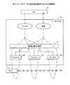
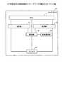
図3は、実施例1に係るリーダライタの構成を示すブロック図である。リーダライタ10は、MPU(Micro Processing Unit)11、送信部12、受信部13、信号分配合成部(信号処理部)14、アンテナ2X〜2Z、制御部19からなる。 FIG. 3 is a block diagram illustrating the configuration of the reader / writer according to the first embodiment. The reader /
MPU11は、アンテナ2X〜2Zを介してタグ1に書き込み/読み出しする情報(データ)を管理する超小型演算装置である。MPU11は、PC5からの指示情報などに基づいて、所定の指示情報を制御部19に送信する。 The
送信部12は、制御部19からの指示情報に基づいてタグ1に書き込ませる所定の情報(コマンド)(通信データ)をRFIDによって送信する。受信部13は、RFIDによってタグ1から所定の情報(応答)を受信する。 The
信号分配合成部14は、送信部12から送信される所定の情報(信号)をアンテナ2X〜2Zに分配する。信号分配合成部14は、アンテナ2X〜2Zが受信する所定の情報を混成(ハイブリッド)して受信部13に送信する。アンテナ2X〜2Zは、それぞれタグ1と情報の送受信を行なう。制御部19は、MPU11からの指示情報に基づいて送信部12、受信部13、信号分配合成部14、アンテナ2X〜2Zを制御する。 The signal distribution /
図4は、各アンテナのデータの送受信を説明するための説明図である。PC5から発行(送信)される制御部19に対するコマンドは、リーダライタ10のMPU11内で解読(解析)されたあと、送信部12からRF(Radio Frequency)信号として出力される。 FIG. 4 is an explanatory diagram for explaining data transmission / reception of each antenna. A command to the
このRF信号は、信号分配合成部14によって各アンテナ(アンテナ2X〜2Z)に分配される。各アンテナ2X〜2Zからは、同時に同じRF信号が出力される。各アンテナ2X〜2Zからのビームがタグ1の移動方向(経路)に対して連続的かつ隙間なく重なるようにアンテナ2X〜2Zが配置されている。これにより、3つのアンテナ2X〜2Zのビーム(信号)範囲内(通信範囲21X〜21Z)を移動するタグ1は同一のRF信号(一連の信号)を途中で途絶えることなく継続して受信できる。また、3つのアンテナ2X〜2Zは、通信範囲21X〜21Zを移動するタグ1から同一のRF信号(応答)を途中で途絶えることなく継続して受信できる。 The RF signal is distributed to each antenna (
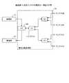
ここで、アンテナの構成について説明する。図5は、実施例1に係るアンテナの構成の一例を示す図である。ここでは、アンテナがアンテナ2W〜2Zの4つからなる場合について説明する。信号分配合成部14は、RF信号の高域濾波器(低域通過)として機能するLPF(Low Pass Filter)140、複数のハイブリッドH1〜H3を備えている。 Here, the configuration of the antenna will be described. FIG. 5 is a diagram illustrating an example of the configuration of the antenna according to the first embodiment. Here, a case where the antenna includes four antennas 2W to 2Z will be described. The signal distribution and
LPF140は、送信部12、受信部13、ハイブリッドH1と接続されている。また、ハイブリッドH1はLPF140、ハイブリッドH2,H3と接続されている。さらに、ハイブリッドH2はアンテナ2W,2Xと接続され、ハイブリッドH2はアンテナ2Y,2Zと接続されている。 The
送信部12から送信(入力)されるRF信号は、LPF140を介してハイブリッドH1に送信される。ハイブリッドH1は、このRF信号を2つの同じRF信号に分配し、分配したそれぞれのRF信号をハイブリッドH2,H3に送信する。ハイブリッドH2は、このRF信号をさらに2つの同じRF信号に分配し、分配したそれぞれのRF信号をアンテナ2W,2Xに送信する。また、ハイブリッドH3は、ハイブリッドH1からのRF信号をさらに2つの同じRF信号に分配し、分配したそれぞれのRF信号をアンテナ2Y,2Zに送信する。 The RF signal transmitted (input) from the
アンテナ2W,2Xがタグ1から受信したRF信号はハイブリッドH2によって論理オアされ、1つのRF信号としてハイブリッドH1に送信される。また、アンテナ2Y,2Zがタグ1から受信したRF信号はハイブリッドH3によって論理オアされ、1つのRF信号としてハイブリッドH1に送信される。 The RF signals received by the
ハイブリッドH2,H3が受信したRF信号はハイブリッドH1によって論理オアされ、1つのRF信号としてLPF140に送信される。そして、LPF140は、このRF信号を受信部13に送信する。これにより、タグ1が4つのアンテナビームの範囲内(通信範囲内)にある限り、リーダライタ10は移動するタグ1からの応答信号等を受信することができる。 The RF signals received by the hybrids H2 and H3 are logically ORed by the hybrid H1 and transmitted to the
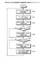
次に、RFIDシステムの処理手順について説明する。ここでは、RFIDシステムの処理手順の一例として、移動するタグ1に対して最初にタグ認識処理(タグ1のアドレス取得)を行い、次にタグ1にデータ書込み処理(タグ書き込み処理)を行う場合について説明する。図6は、実施例1に係るRFIDシステムのタグ認識処理の手順を示すフローチャートである。 Next, the processing procedure of the RFID system will be described. Here, as an example of the processing procedure of the RFID system, a tag recognition process (tag 1 address acquisition) is first performed on a moving
PC5(上位PC)は、リーダライタ10に対し、タグ1を認識するための指示情報として「タグ認識依頼」を発行する(ステップS100)。リーダライタ10のMPU11は、PC5からの「タグ認識依頼」の内容を解析した後(ステップS110)、制御部19に対して「タグ認識依頼」のコマンドを発行する(ステップS120)。 The PC 5 (upper PC) issues a “tag recognition request” as instruction information for recognizing the
制御部19は、タグ1のアドレスを取得するためのコマンドとして「タグ認識コマンド」を一連のビット列としてエアー上に送出(送信)するよう送信部12を制御する。送信部12からの「タグ認識コマンド」は、信号分配合成部14、アンテナ2X〜2Zを介して通信範囲21X〜21Z(通信可能エリア20)に送出される(ステップS130)。タグ1は、リーダライタ10から「タグ認識コマンド」を受信すると「タグ認識コマンド」に対する応答として「アドレス応答」を送信する。 The
図7はタグ認識コマンドのフォーマットの一例を示す図であり、図8は、アドレス応答のフォーマットの一例を示す図である。図7に示すように「タグ認識コマンド」は、プリアンブル、デリミタ、コマンド、アドレス、マスク、データ、CRC(Cyclic Redundancy Check)からなる。 FIG. 7 is a diagram showing an example of the format of the tag recognition command, and FIG. 8 is a diagram showing an example of the format of the address response. As shown in FIG. 7, the “tag recognition command” includes a preamble, a delimiter, a command, an address, a mask, data, and a CRC (Cyclic Redundancy Check).
プリアンブルは、受信側(タグ1)で同期化を行なうためのフィールドであり、予め定められた固定パターンが示される。デリミタは、タグ1とリーダライタ10の間の伝送モード(通信速度等)を決めるパラメータである。 The preamble is a field for performing synchronization on the receiving side (tag 1), and indicates a predetermined fixed pattern. The delimiter is a parameter that determines a transmission mode (communication speed or the like) between the
コマンドは、タグ1の認識処理(アドレスの取得)を表すコマンドコードである。アドレスは、タグ1をグループ識別する際の比較情報の先頭アドレスを示す。このアドレス領域の情報(8バイト)とデータの情報(8バイト)との比較結果によってタグ1に応答をさせるか否かの選択をすることができる。 The command is a command
マスクは、タグ1をグループ識別する際の比較のマスクを示す。マスクが「0」の場合、全てのタグが認識処理の対象となる。データは、タグ1をグループ識別する際の比較情報を示す。このデータ領域の情報(8バイト)と前述のアドレス領域の情報(8バイト)との比較結果によりタグ1に応答をさせるか否かの選択をすることができる。CRCは、送信データ(タグ認識コマンド)に対するチェックコードである。 The mask indicates a comparison mask used for group identification of the
プリアンブルは例えば10ビットであり、デリミタは例えば1バイトであり、コマンドは例えば1バイトであり、アドレスは例えば1バイトであり、マスクは例えば1バイトであり、データは例えば8バイトであり、CRCは例えば2バイトである。すなわち、「タグ認識コマンド」は例えば約16バイトの大きさを有している。 The preamble is, for example, 10 bits, the delimiter is, for example, 1 byte, the command is, for example, 1 byte, the address is, for example, 1 byte, the mask is, for example, 1 byte, the data is, for example, 8 bytes, and the CRC is, for example, For example, 2 bytes. That is, the “tag recognition command” has a size of about 16 bytes, for example.
図8に示すように「アドレス応答」は、プリアンブル、ID、CRCからなる。ここでのプリアンブルは、リーダライタ10側で同期をとるために予め定められた固定パターンである。IDは、タグ1のアドレス情報(8バイト固定)である。ここでのCRCは、返信データ(アドレス応答)に対するチェックコードである。 As shown in FIG. 8, the “address response” includes a preamble, an ID, and a CRC. The preamble here is a fixed pattern determined in advance for synchronization on the reader /
プリアンブルは例えば約10ビットであり、IDは例えば8バイトであり、CRCは例えば2バイトである。すなわち、「アドレス応答」は例えば、約12バイトの大きさを有している。「タグ認識コマンド」や「アドレス応答」は、例えば10Kbps(Bit Per Second)の伝送速度で送受信される。 The preamble is, for example, about 10 bits, the ID is, for example, 8 bytes, and the CRC is, for example, 2 bytes. That is, the “address response” has a size of about 12 bytes, for example. The “tag recognition command” and “address response” are transmitted and received at a transmission rate of 10 Kbps (Bit Per Second), for example.
MPU11は、タグ1から「アドレス応答」を受信したか否か(タグ1から応答があったか否か)を確認する(ステップS140)。リーダライタ10は、「タグ認識コマンド」を送信した後、タグ1が「アドレス応答」を送信してれば(ステップS140、Yes)、この「アドレス応答」を受信部13によって受信する(ステップS150)。ここでの受信部13は、アンテナ2X〜2Z、信号分配合成部14を介して「タグ認識コマンド」を受信する。すなわち、実施例1においてはタグ1はアンテナ2X〜2Zから「タグ認識コマンド」を受信し、タグ1はアンテナ2X〜2Zに「アドレス応答」を送信する。 The
リーダライタ10の制御部19は、「タグ認識コマンド」を送信して所定の時間が経過するまでに、タグ1から「アドレス応答」を受信すると、MPU11に対して、タグ1のアドレス認識の処理が完了したことを報告(通知)する(ステップS160)。一方、リーダライタ10の制御部19は、「タグ認識コマンド」を送信して所定の時間が経過するまでに、タグ1から「アドレス応答」を受信しないと(ステップS140、No)、MPU11に対して、タグ1が検出できなかったことを報告する(ステップS160)。 When the
タグ1からの「アドレス応答」の内容にCRCエラー等の異常が検出された場合やタグ1からの「アドレス応答」が検出できなかった場合、MPU11は制御部19に再度「タグ認識コマンド」を送出するよう「タグ認識コマンド」の送出処理を依頼(リトライ)する。 When an abnormality such as a CRC error is detected in the content of the “address response” from the
アクセス対象であるタグ1は移動している。このため、リーダライタ10が行なう「タグ認識コマンド」の送出処理のリトライの可否やリトライの許容回数は、タグ1との通信可能範囲、タグ1の移動速度、タグ1との間で送受信する最大データ量等に基づいて、リーダライタ10に予め設定しておく。 The
リーダライタ10のMPU11は、「タグ認識コマンド」の送出処理のリトライが予め設定しておいた回数(例えば10回)を超えたか否かを確認する(ステップS170)。MPU11は、「タグ認識コマンド」の送出処理のリトライが予め設定しておいた回数を超えていないと判断した場合(ステップS170、No)、送信部12がタグ1から「アドレス応答」を受信したか否かを確認する(ステップS180)。 The
送信部12がタグ1から「アドレス応答」を受信している場合、MPU11はこの「アドレス応答」の内容の妥当性を確認する(ステップS190,S200)。ここでの、タグ1からの「アドレス応答」の内容の妥当性は、例えばCRCエラー、符号化エラー、プリアンブルエラー等の有無を確認することによって行なう。 When the
MPU11は、「アドレス応答」の内容が妥当である(異常なし)と判断すると(ステップS200、Yes)、受信部13が受信した「アドレス応答」をPC5に送信する。タグ1からの「アドレス応答」が検出できなかった場合や(ステップS180、No)、タグ1からの「アドレス応答」の内容にCRCエラー等の異常が検出された場合(ステップS200、No)、MPU11は制御部19に再度「タグ認識コマンド」を送出するよう「タグ認識コマンド」の送出処理を依頼する(ステップS120)。 When the
制御部19は、MPU11から「タグ認識コマンド」のリトライを依頼されると、ステップS130〜S160の処理によって「タグ認識コマンド」の送出処理と「アドレス応答」の受信処理を行なう。 When the
リーダライタ10は、MPU11によって「タグ認識コマンド」の送出処理のリトライが予め設定しておいた回数を超えたか否かを確認する(ステップS170)。「タグ認識コマンド」の送出処理のリトライ回数が、予め設定しておいた回数(許容回数)を超えた場合、MPU11はタグ1が通信可能エリア20から外れた(読み飛ばし発生)と判断し、タイムアウトとしてPC5に通知する(ステップS210)。 The reader /
PC5は、リーダライタ10から「アドレス応答」を受信し、「アドレス応答」の内容を確認する(ステップS220)。PC5は、タグ1から「アドレス応答」を所定の時間内に正常に取得できた場合(ステップS230〜S250)、リーダライタ10は取得できたタグ1のアドレスを使ってタグ1への情報の書込み処理を行なう。一方、ステップS210におけるタイムアウト等の異常が発生した場合は、リーダライタ10は処理エラーと判断してタグ1への情報の書き込み処理を行なわない。 The
図9は、実施例1に係るRFIDシステムのタグ書き込み処理の手順を示すフローチャートである。RFIDシステムによるタグ書き込み処理の処理手順は、タグ認識処理の処理手順と同様の処理手順によって行なう。すなわち、PC5はリーダライタ10に対し、タグ1に情報を書き込むための指示情報としてタグ1のアドレスを指定した「タグWrite依頼」を発行する(ステップS300)。 FIG. 9 is a flowchart illustrating the procedure of the tag writing process of the RFID system according to the first embodiment. The processing procedure of the tag writing process by the RFID system is performed by the same processing procedure as that of the tag recognition process. That is, the
リーダライタ10のMPU11は、PC5からの「タグWrite依頼」の内容を解析した後(ステップS310)、制御部19に対してタグ1に情報を書き込むための「Write依頼」のコマンドを発行する(ステップS320)。 After analyzing the content of the “tag write request” from the PC 5 (step S310), the
制御部19は、タグ1に情報を書き込むためのコマンドとして「Writeコマンド」を、一連のビット列としてエアー上に送出するよう送信部12を制御する。送信部12からの「Write依頼コマンド」は、信号分配合成部14、アンテナ2X〜2Zを介して通信範囲21X〜21Z(通信可能エリア20)に送出される(ステップS330)。 The
タグ1は、リーダライタ10のアンテナ2X〜2Zから「Writeコマンド」を受信すると、「Writeコマンド」に応じた情報を書き込む。そして、タグ1は書き込み処理が終了したことを示す「書き込み応答」をアンテナ2X〜2Zに送信する。 When the
図10はWriteコマンドのフォーマットの一例を示す図であり、図11は書き込み応答のフォーマットの一例を示す図である。図10に示すように「Writeコマンド」は、プリアンブル、デリミタ、コマンド、ID、アドレス、データ、CRCからなる。 ここでのコマンドは、タグ1に対する情報の書き込み処理を表すコマンドコードである。ここでのアドレスは、タグ1内にデータを書き込む際の先頭アドレスを示す。ここでのデータは、タグ1に書き込む書込みデータ(4バイト固定)である。ここでのCRCは、送信データ(Writeコマンド)に対するチェックコードである。 FIG. 10 is a diagram showing an example of the format of the Write command, and FIG. 11 is a diagram showing an example of the format of the write response. As shown in FIG. 10, the “Write command” includes a preamble, a delimiter, a command, an ID, an address, data, and a CRC. The command here is a command code representing a process of writing information to the
プリアンブルは例えば10ビットであり、デリミタは例えば1バイトであり、コマンドは例えば1バイトであり、IDは例えば8バイトであり、アドレスは例えば1バイトであり、データは例えば4バイトであり、CRCは例えば2バイトである。すなわち、「Writeコマンド」は例えば、約19バイトの大きさを有している。 The preamble is, for example, 10 bits, the delimiter is, for example, 1 byte, the command is, for example, 1 byte, the ID is, for example, 8 bytes, the address is, for example, 1 byte, the data is, for example, 4 bytes, and the CRC is For example, 2 bytes. That is, the “Write command” has a size of about 19 bytes, for example.
ここでのプリアンブルは、リーダライタ10側で同期をとるために予め定められた固定パターンである。応答は、書込み処理に対する結果を表す。ここでのCRCは、返信データ(書き込み応答)に対するチェックコードである。 The preamble here is a fixed pattern determined in advance for synchronization on the reader /
プリアンブルは例えば10ビットであり、応答は例えば1バイトであり、CRCは例えば2バイトである。すなわち、「書き込み応答」は例えば、約5バイトの大きさを有している。「Writeコマンド」や「書き込み応答」は、例えば10Kbpsの伝送速度で送受信される。 The preamble is, for example, 10 bits, the response is, for example, 1 byte, and the CRC is, for example, 2 bytes. That is, the “write response” has a size of about 5 bytes, for example. The “Write command” and “write response” are transmitted and received at a transmission rate of 10 Kbps, for example.
MPU11は、タグ1から「書き込み応答」を受信したか否かを確認する(ステップS340)。リーダライタ10は、「Write依頼コマンド」を送信した後、タグ1が「書き込み応答」を送信してれば(ステップS340、Yes)、受信部13によって「書き込み応答」を受信する(ステップS350)。ここでの受信部13は、アンテナ2X〜2Z、信号分配合成部14を介して「書き込み応答」を受信する。すなわち、実施例1においてはタグ1はアンテナ2X〜2Zから「Write依頼」を受信し、タグ1はアンテナ2X〜2Zに「書き込み応答」を送信する。 The
リーダライタ10の制御部19は、「タグ認識コマンド」を送信して所定の時間が経過するまでにタグ1から「アドレス応答」を受信すると、MPU11に対して、タグ1のアドレス認識の処理が完了したことを報告する(ステップS360)。一方、リーダライタ10の制御部19は、「Write依頼コマンド」を送信して所定の時間が経過するまでに、タグ1から「書き込み応答」を受信しないと(ステップS340、No)、MPU11に対して、タグ1への書き込みができなかったことを報告する(ステップS360)。この後、図5に示したタグ認識処理と同様の処理手順によってタグ1への書き込み処理のリトライ等を行なうためその説明は省略する。 When the
ここで、ステップS130〜S150,S330〜S350の処理である、アンテナ2X〜2Zとタグ1の間で送受信される通信データ(「タグ認識コマンド」、「アドレス応答」、「Writeコマンド」、「書き込み応答」)と時間の関係について説明する。 Here, the communication data (“tag recognition command”, “address response”, “write command”, “write”) transmitted / received between the
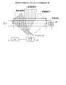
図12は、各アンテナが送受信する通信データを説明するための説明図である。図12において、横軸は時間を示しており、通信データとしてリーダライタ10から送出されるコマンド(「タグ認識コマンド」、「Writeコマンド」)とタグ1から送出される応答情報(「アドレス応答」、「書き込み応答」)を時系列に示している。ここでは、時間の経過が横軸を左側から右側へ流れる場合を示している。 FIG. 12 is an explanatory diagram for explaining communication data transmitted and received by each antenna. In FIG. 12, the horizontal axis indicates time, and commands sent from the reader /
また、図11の下部には通信データの送受信の際の経過時間に対する各アンテナ2X〜2Zの受信状態を示している。すなわち、アンテナ2Xは通信範囲21Xでタグ1と有効データの送受信を行い、アンテナ2Yは通信範囲21Yでタグ1と有効データの送受信を行い、アンテナ2Zは通信範囲21Zでタグ1と有効データの送受信を行う。また、タグ1はアンテナ2Xからアンテナ2Yを介してアンテナ2Zの方向へ移動している。 Moreover, the lower part of FIG. 11 shows the reception state of each
リーダライタ10からのコマンドおよびタグ1からの応答情報は図5,8のフローチャートで説明したように、最初にリーダライタ10からタグ1へ「タグ認識コマンド」が送信され、続いてタグ1からリーダライタ10へ「アドレス応答」が送信される。次にリーダライタ10からタグ1へ「Writeコマンド」が送信され、続いてこれに対するタグ1からの「書き込み応答」がリーダライタ10に送信される。 As described with reference to the flowcharts of FIGS. 5 and 8, the command from the reader /
タグ1は、通信範囲21Xにおいてはアンテナ2Xと通信を行い、通信範囲21Yにおいてはアンテナ2Yと通信を行い、通信範囲21Zにおいてはアンテナ2Zと通信を行う。アンテナ2Xの通信範囲21Xとアンテナ2Yの通信範囲21Yは部分的に重なっているとともに、アンテナ2Yの通信範囲21Yとアンテナ2Zの通信範囲21Zは部分的に重なっている。すなわち、アンテナ2X〜2Zは、アンテナ2X〜2Zの通信範囲21X〜21Zが移動経路51に沿って連続するよう配置されている。したがって、タグ1は、通信範囲21Xと通信範囲21Yの重なっているエリアにおいてはアンテナ2Xとアンテナ2Yの両方のアンテナと通信を行う。また、通信範囲21Yと通信範囲21Zの重なっているエリアにおいてはアンテナ2Yとアンテナ2Zの両方のアンテナと通信を行う。 The
これにより、タグ1は通信可能エリア20においてデータ通信路が途切れることなくリーダライタ10と通信を行っている。換言すると、リーダライタ10とタグ1との間の通信は、1つのコマンドパケットの送受信(コマンドシーケンス)が複数のアンテナの通信範囲に跨っている場合であっても、各アンテナ2X〜2Zの移り変わりやコマンド/データパケットおよびシーケンスの区切りとは関係なく行われる。 As a result, the
例えばタグ1(移動対象50)を移動させるベルトコンベアの移動速度が3m/sであり、1つのアンテナの通信可能範囲Lが1mである場合、タグ1とリーダライタ10の1つのアンテナ間の通信可能時間は1/3秒間(約333ms)となる。 For example, when the moving speed of the belt conveyor for moving the tag 1 (moving target 50) is 3 m / s and the communicable range L of one antenna is 1 m, communication between the
リーダライタ10とタグ1の間のコマンド/レスポンスのデータ伝送速度を10Kbps(=1バイト時間0.8ms)とした場合に必要な各処理時間は例えば以下のようになる。
・(1)MPU11内における認識コマンドの作成時間=約0.5ms(図示せず)
・(2)送信部12からタグ1への「タグ認識コマンド」の転送時間(約16バイト)=約13ms
・(3)タグ1内の処理時間=約0.5ms(図示せず)
・(4)タグ1からリーダライタ10への「アドレス応答」の転送時間(約12バイト)=約10ms
・(5)MPU11内の処理時間=約0.5ms(図示せず)
・(6)MPU11からタグ1への「Writeコマンド」の転送時間(約19バイト)=約16ms
・(7)タグ1内の処理時間=約0.5ms(図示せず)
・(8)タグ1からリーダライタ10への「書き込み応答」の転送時間(約5バイト)=約4msEach processing time required when the command / response data transmission speed between the reader /
(1) Recognition command creation time in the
(2) Transfer time of the “tag recognition command” from the
(3) Processing time in
(4) “Address response” transfer time from
(5) Processing time in the
(6) Transfer time of “Write command” from the
(7) Processing time in
(8) Transfer time of the “write response” from the
これら(1)〜(8)の一連の処理時間を合計すると約45msであり、アンテナ1つ分の通信可能範囲で得られる通信時間333msで充分な時間となっている。また通信中のノイズによるデータ破壊によるリトライ処理時間や通信データ量の増加に対しても余裕のある時間となっている。 The total processing time of these (1) to (8) is about 45 ms, and the communication time of 333 ms obtained in the communicable range for one antenna is sufficient. In addition, there is a sufficient time for a retry processing time due to data destruction due to noise during communication and an increase in the amount of communication data.
このようなRFIDシステムにおいて、作業効率を上げるためにベルトコンベアの速度を3m/sの10倍の速度である30m/sに上げた場合について説明する。この場合、タグ1とリーダライタ10が通信可能な時間は333msの1/10倍である33.3msとなる。したがって、タグ1とリーダライタ10の1つのアンテナが通信可能な時間は、先述した(1)〜(8)の一連の処理時間(45ms)より短くなる。 In such an RFID system, a case where the speed of the belt conveyor is increased to 30 m / s, which is 10 times the speed of 3 m / s, in order to increase the working efficiency will be described. In this case, the time during which the
このような場合であっても、RFIDシステムが連続的に3つのアンテナ2X〜2Zを配置していれば、リーダライタ10は1つのアンテナの場合に比べて約3倍(33.3ms×3=約100ms)の通信可能時間を得ることが可能となる。 Even in such a case, if the RFID system continuously arranges the three
この通信可能時間(約100ms)は、(1)〜(8)の一連の処理時間(約45ms)に対しては充分な時間であり、異常時のリトライやタグ1との通信データ量の増加に対しても対応可能な時間となる。 This communicable time (about 100 ms) is sufficient for the series of processing times (about 45 ms) of (1) to (8), and retry at the time of abnormality and increase in the amount of communication data with the
例えば、リーダライタ10からの「タグ認識コマンド」は、最初アンテナ2Xによって受信され始める。例えば、アンテナ2Xは「タグ認識コマンド」のプリアンブルからコマンドまでを受信する。 For example, the “tag recognition command” from the reader /
タグ1が通信範囲21Xから通信範囲21Xと通信範囲21Yの重複エリアに移動すると、「タグ認識コマンド」はアンテナ2Xとアンテナ2Yによって受信される。例えば、アンテナ2X,2Yによって「タグ認識コマンド」のアドレスを受信する。 When the
タグ1が通信範囲21Xと通信範囲21Yの重複エリアから通信範囲21Yに移動すると、「タグ認識コマンド」はアンテナ2Yによって受信される。例えば、アンテナ2Yによって「タグ認識コマンド」のマスクからCRCまでを受信する。 When the
タグ1が通信範囲21Yに位置する際に「アドレス応答」を送信すると、アンテナ2Yがこの「アドレス応答」を受信する。例えば、アンテナ2Yによって「アドレス応答」のプリアンブルからCRCまでの全てを受信する。 When the “address response” is transmitted when the
タグ1が通信範囲21Yに位置する際にリーダライタ10から「Writeコマンド」が送信されると、「Writeコマンド」はアンテナ2Yによって受信され始める。例えば、アンテナ2Yによって「Writeコマンド」のプリアンブルからアドレスまでを受信する。 When the “Write command” is transmitted from the reader /
タグ1が通信範囲21Yから通信範囲21Yと通信範囲21Zの重複エリアに移動すると、「Writeコマンド」はアンテナ2Yとアンテナ2Zによって受信される。例えば、アンテナ2Y,2Zによって「Writeコマンド」のデータを受信する。 When the
タグ1が通信範囲21Yと通信範囲21Zの重複エリアから通信範囲21Zに移動すると、「Writeコマンド」はアンテナ2Zによって受信される。例えば、アンテナ2Zによって「Writeコマンド」のCRCを受信する。 When the
タグ1が通信範囲21Zに位置する際に「書き込み応答」を送信すると、アンテナ2Zがこの「書き込み応答」を受信する。例えば、アンテナ2Zによって「書き込み応答」のプリアンブルからCRCまでの全てを受信する。 When the “write response” is transmitted when the
このように、リーダライタ10が複数のアンテナ2X〜2Zを備えることによって、リーダライタ10はタグ1との通信エリアを拡張することができるとともに、タグ1がアンテナ2X〜2Z(通信範囲21X〜21Z)間を移動した場合にデータ通信路を遮断することなく通信の連続性を保証することができる。 As described above, the reader /
なお、本実施例1においては、リーダライタ10が3つのアンテナ2X〜2Zを備える構成としたが、リーダライタ10は2つのアンテナまたは4つ以上のアンテナを備える構成としてもよい。 In the first embodiment, the reader /
なお、本実施例1においては、タグ1がベルトコンベア上を直線的に移動する場合について説明したが、タグ1は直線的に移動する場合に限られない。すなわち、タグ1の移動経路51が曲線を含む場合、タグ1の移動経路51に応じてアンテナ2X〜2Zを配置する。この場合、アンテナ2X〜2Zはアンテナ2X〜2Zの各通信範囲21X〜21Zが曲線を含む移動経路51と重なるようアンテナ2X〜2Zを配置する。 In the first embodiment, the case where the
また、本実施例1においては、タグ1がベルトコンベア上の平面内を移動する場合について説明したが、タグ1は平面内を移動する場合に限られない。すなわち、タグ1の移動経路51が3次元方向の移動経路を含む場合であっても、タグ1の移動経路51に応じてアンテナ2X〜2Zを配置する。この場合も、アンテナ2X〜2Zはアンテナ2X〜2Zの各通信範囲21X〜21Zが3次元方向の移動経路51と重なるようアンテナ2X〜2Zを配置する。 In the first embodiment, the case in which the
このように、複数のアンテナ2X〜2Zによって通信可能エリア20を拡張できるとともに、通信可能エリア20における通信線路の連続性を得ることが可能となる。したがって、タグ1とリーダライタ10間においてデータ通信を行なうことが可能な時間を延ばすことが可能となり、高速移動するタグ1と通信を行なうことやタグ1とリーダライタ10間で多くの通信データ量を送受信することが可能となる。 Thus, the communicable area 20 can be expanded by the plurality of
このように実施例1によれば、複数のアンテナ2X〜2Zを配置することによって、タグ1の送信能力を変えることなくタグ1が有する情報の読み取り空間を広げることが可能となる。したがって、リーダライタ10とタグ1の間の通信速度やプロトコル等の通信条件を変えることなく、タグ1の移動(ベルトコンベアの速度)の高速化が可能であり、リーダライタ10によるタグ1のタグ認識処理、タグ1への情報の書き込み/読み出し処理を効率良く行うことが可能となる。 As described above, according to the first embodiment, by arranging the plurality of
次に、図13〜15を用いてこの発明の実施例2について説明する。実施例2ではリーダライタのアンテナを回転等させることによって、アンテナの通信範囲を拡大する。アンテナの回転等は、アンテナの通信範囲がタグ1の移動に追従するよう行なう。 Next,
図13は実施例2に係るRFIDシステムのシステム構成を示す図であり、図14は実施例2に係るリーダライタの構成を示すブロック図である。図13および図14の各構成要素のうち図2および図3に示す実施例1のRFIDシステムやリーダライタ10と同一機能を達成する構成要素については同一番号を付しており、重複する説明は省略する。 FIG. 13 is a diagram illustrating a system configuration of the RFID system according to the second embodiment, and FIG. 14 is a block diagram illustrating a configuration of the reader / writer according to the second embodiment. Of the components shown in FIGS. 13 and 14, components that achieve the same functions as those of the RFID system and the reader /
RFIDシステムは、PC5、リーダライタ30、アンテナ2R、移動対象50、タグ1からなる。アンテナ2Rは、通信範囲P1〜Pn(nは自然数)内でタグ1と情報の送受信を行う。ここでは、通信範囲P1〜Pnが、タグ1とリーダライタ30が情報の送受信を行うことが可能なエリアである通信可能エリア20となる。 The RFID system includes a
図14に示すようにリーダライタ30は、MPU11、送信部12、受信部13、回転制御部(方向制御部)31、アンテナ2Rからなる。アンテナ2Rは回転可能なアンテナであり、タグ1と情報の送受信を行う。 As shown in FIG. 14, the reader /
回転制御部31は、アンテナ2Rの配置される方向を制御することによって、アンテナ2Rの通信範囲の方向(位置)を通信範囲P1〜Pnのいずれかに変化させる。すなわち、回転制御部31はアンテナ2Rが行う通信の指向方向を制御する。回転制御部31は、アンテナ2Rの通信範囲がタグ1の移動に追従するようアンテナ2Rの方向を、通信範囲P1〜Pnのいずれかの方向に制御する。回転制御部31は、アンテナ2Rの配置される方向を、例えば円形や楕円形の円弧上、タグ1の移動方向と平行な直線上に変化させることによってアンテナ2Rの方向を制御する。回転制御部31は、例えばアンテナ2Rのビーム角度(通信範囲P1〜Pnによる通信可能エリア20)が180度をカバーするようアンテナ2Rの方向を制御する。 The
次に、本実施例2に係るRFIDシステムの処理手順について説明する。図15は、実施例2に係るRFIDシステムのタグ認識処理の手順を示すフローチャートである。タグ1が貼り付けられた移動対象50は、ベルトコンベア上の移動経路51に従って移動する(ステップS500)。 Next, a processing procedure of the RFID system according to the second embodiment will be described. FIG. 15 is a flowchart illustrating a procedure of tag recognition processing of the RFID system according to the second embodiment. The moving
アンテナ2Rは、ビーム方向(通信範囲の中心方向)がタグ1の移動経路51と平行な方向に予め向けられている。すなわち、アンテナ2Rの初期位置はタグ1が移動してくる方向(右側0度)を向いている。 The
リーダライタ10がアンテナ2Rを介してタグ1との通信を開始(タグ1からの応答情報を受信)すると、回転制御部31はアンテナ2Rをタグ1の移動に追従して回転等させる。ここでは、回転制御部31は予めベルトコンベアの速度に基づいてアンテナ2Rを回転させる速度を算出しておく。そして、回転制御部31は予め算出しておいた速度に応じてアンテナ2Rを回転させる(ステップS510)。 When the reader /
回転制御部31がアンテナ2Rの方向を制御するとともに、送信部12はアンテナ2Rを介してタグ1に「タグ認識コマンド」や「Writeコマンド」等のコマンドを送信する(ステップS520)。さらに、回転制御部31がアンテナ2Rの方向を制御するとともに、受信部13はアンテナ2Rを介してタグ1から「アドレス応答」や「書き込み応答」等の応答を受信する(ステップS530)。 The
回転制御部31は、アンテナ2Rを例えばビーム方向がタグ1の移動経路と平行な方向(右側0度)から時計と逆回りの方向へ回転させる。そして、回転制御部31はアンテナ2Rを例えばビーム方向がタグ1の移動経路と平行な方向(右側180度)まで回転させるとアンテナ2Rによるタグ1の追従制御を終了する。また、回転制御部31はタグ1からアドレス応答や書き込み応答を受信した際にアンテナ2Rによるタグ1の追従制御を終了してもよい。 The
回転制御部31は、1つのタグ1に対してアンテナ2Rの向く方向を制御すると次のタグ1に対してアンテナ2Rの向く方向を制御する。回転制御部31は、1つのタグ1に対してアンテナ2Rの向く方向を制御した後、アンテナ2Rが初期位置(右側0度)に向くようアンテナ2Rを制御する。すなわち、回転制御部31は最初にタグ1の情報を受信した後、タグ1の情報が受信できなくなった時点で再び逆側(右側0度)に向くようアンテナ2Rを制御する。このように、アンテナ2Rを例えば移動経路51と平行な方向(右側0度または右側180度)を向くよう制御することによってタグ1との通信可能エリアを広くすることができる。 When the
回転制御部31は、アンテナ2Rを右側0度から180度回転させる場合に限られず、例えば図13に示すようにアンテナ2Rの通信範囲が通信範囲P1,P2〜通信範囲Pnの方向に向くよう制御してもよい。 The
また、1つのタグ1に対してアンテナ2Rの向く方向の制御を行なった後、次のタグ1に対してアンテナ2Rの向く方向の制御として、次のタグ1の位置する方向に向くようアンテナ2Rの初期位置を制御してもよい。 In addition, after controlling the direction in which the
なお、本実施例2においては、タグ1がベルトコンベア上を直線的に移動する場合について説明したが、タグ1は直線的に移動する場合に限られない。すなわち、タグ1の移動経路51が曲線を含む場合は、タグ1の移動経路51に応じてアンテナ2Rの方向を変化させる。この場合、回転制御部31はアンテナ2Rの通信範囲21Rが曲線を含む移動経路51に重なるようアンテナ2Rの方向を制御する。 In addition, in the present Example 2, although the case where the
また、本実施例2においては、タグ1がベルトコンベア上の平面内を移動する場合について説明したが、タグ1は平面内を移動する場合に限られない。すなわち、タグ1の移動経路51が3次元方向の移動経路を含む場合であっても、タグ1の移動経路51に応じてアンテナ2Rの方向を変化させる。この場合も、回転制御部31はアンテナ2Rの通信範囲21Rが3次元方向の移動経路51と重なるようアンテナ2Rの方向を制御する。 In the second embodiment, the case where the
このように実施例2によれば、リーダライタ10とタグ1の間の通信速度やプロトコル等の通信条件を変えることなく、アンテナ2Rの向く方向を制御することによって簡易な構成でタグ1が有する情報の読み取り空間を広げることが可能となる。したがって、タグ1の移動の高速化が可能となり、リーダライタ10によるタグ1のタグ認識処理、タグ1への情報の書き込み/読み出し処理を効率良く行うことが可能となる。 Thus, according to the second embodiment, the
次に、図16〜21を用いてこの発明の実施例3について説明する。実施例3ではRFIDシステムがタグの移動順序を認識するリーダライタ(第1のリーダライタ)41とタグに書き込み/読み出し処理を行なうリーダライタ(第2のリーダライタ)42Aを備える。 Next,
図16は実施例3に係るRFIDシステムのシステム構成を示す図であり、図17はタグ移動順序の認識処理を行なうリーダライタの構成を示すブロック図であり、図18はタグへの書き込み/読み出し処理を行なうリーダライタの構成を示すブロック図である。図16、図17および図18の各構成要素のうち図2および図3に示す実施例1のRFIDシステムやリーダライタ10と同一機能を達成する構成要素については同一番号を付しており、重複する説明は省略する。 FIG. 16 is a diagram illustrating a system configuration of an RFID system according to the third embodiment, FIG. 17 is a block diagram illustrating a configuration of a reader / writer that performs a tag movement order recognition process, and FIG. It is a block diagram which shows the structure of the reader / writer which performs a process. 16, 17, and 18, components that achieve the same functions as those of the RFID system and the reader /
図16に示すようにRFIDシステムは、PC5、リーダライタ41,42A、アンテナ2P,2A、複数の移動対象50、各移動対象50に貼り付けられたタグ1からなる。リーダライタ41は、移動対象50(タグ1)の移動経路51において、リーダライタ42Aよりタグ1の流れの上流側(図面の右側)に配置される。リーダライタ41は、ベルトコンベア上を流れてくる複数のタグ1と通信を行い、各タグ1が流れてくる順番(タグ1と通信を行う通信範囲内から通信範囲外に、またはタグ1と通信を行う通信範囲外から通信範囲内に移動していくタグ1の順番)に関する情報(後述するタグ管理情報90)を生成する。 As shown in FIG. 16, the RFID system includes a
リーダライタ42Aは、移動対象50(タグ1)の移動経路51において、リーダライタ41よりタグ1の流れの下流側(図面の左側)に配置される。リーダライタ42Aは、ベルトコンベア上を流れてくる複数のタグ1と通信を行い、リーダライタ41が生成したタグ管理情報90内の後述する順序管理テーブル92Aに従って各タグ1に読み取り/書き込み処理を行なう。 The reader /
アンテナ2Pは、リーダライタ41に接続され、通信範囲21Pでタグ1と通信を行う。アンテナ2Aは、リーダライタ42Aに接続され、通信範囲21Aでタグ1と通信を行う。PC5は、リーダライタ41,42AとLAN49によって接続され、リーダライタ41,42Aが取得したタグ1の情報を管理する。 The
図17に示すようにリーダライタ41は、MPU11、送信部12、受信部13、順番管理部(順序情報生成部)45、アンテナ2Pからなる。順番管理部45は、受信部13がタグ1から受信する「アドレス応答」に基づいてタグ1が流れてくる順番に関する情報(順序情報)を生成する。リーダライタ41の順番管理部45は、アンチコリジョンアルゴリズム(認識)(複数のタグ1の同時読み取り)によって刻々と(順番に)流れる複数のタグ1(アドレス)を連続的に読み取り、アンテナ2Pの通信範囲21Pに入ってくる(新たに追加された)タグ1と、アンテナ2の通信範囲21Pから外れていく(消えていく)タグ1の関係からタグ1の流れる順番を検出し、タグ1の流れ順を示すタグ1の管理表(タグ管理情報90)を生成する。 As shown in FIG. 17, the reader /
順番管理部45は、タグ管理情報90として、タグ1が出現した(タグ1が通信範囲21P内に移動してきた)順番と各タグ1のタグアドレスの対応関係を示す後述の出現タグ管理テーブル91と、タグ1が消えた(タグ1が通信範囲21P外に移動した)順番をタグ1の移動順序として示す後述の順序管理テーブル92Aを生成する。 The
図18に示すようにリーダライタ42Aは、MPU11、送信部12、受信部13、通信管理部(通信部)47、アンテナ2Aからなる。通信管理部47は、リーダライタ41の順番管理部45が生成したタグ管理情報90に従ってタグ1への読み込み/書き込み処理を行なう。 As shown in FIG. 18, the reader /
次に、実施例3に係るRFIDシステムの処理手順について説明する。図19は、実施例3に係るタグ移動順序の認識処理の手順を示すフローチャートである。リーダライタ41の順番管理部45は、タグ1の移動順序(タグ移動順序)を示すタグ管理情報90を作成するため、1ラウンドのコリジョンアービトレーション(所定の時点)によって認識できるタグ1の全てのアドレスを検出する(ステップS600,S610)。すなわち、リーダライタ41では1ラウンドのコリジョンアービトレーション期間が所定の条件に収まるサイクルでアンチコリジョンを行い、順番管理部45は1サイクル毎に出現タグ管理テーブル91と順序管理テーブル92Aの更新処理を行う。 Next, a processing procedure of the RFID system according to the third embodiment will be described. FIG. 19 is a flowchart of a tag movement order recognition process according to the third embodiment. Since the
ここで、コリジョンアービトレーション期間とタグ1の移動時間の関係について説明する。コリジョンアービトレーションの1ラウンドに要する時間をコリジョンアービトレーション期間(T)(sec)とし、タグ1の移動する速度を移動速度(S)(m/sec)とし、タグ1とリーダライタ41が通信可能な範囲を通信可能範囲L(m)とする。 Here, the relationship between the collision arbitration period and the movement time of the
1ラウンドのコリジョンアービトレーション期間(T)中に新たに通信範囲21P内に入ってきたタグ1の次のラウンドでの読み取りが保証されるための条件は、1ラウンド時間のタグ1の移動距離(TS)が、通信可能範囲(L)の1/2を超えないことである。この条件は、式(2)によって示される。
TS≦L/2・・・(2)The condition for guaranteeing the reading of the
TS ≦ L / 2 (2)
ここで、コリジョンアービトレーション期間(T)は、処理するタグ数をN、タグ処理速度をMとして、式(3)によって表される。
T=N/M・・・(3)Here, the collision arbitration period (T) is expressed by Equation (3), where N is the number of tags to be processed and M is the tag processing speed.
T = N / M (3)
したがって、移動速度(S)は式(4)によって示される。
S≦L/2T=ML/2N・・・(4)
例えば、1ラウンドでリーダライタ41が処理可能なタグ数Nは、通信可能範囲(L)を1m、タグ1間の距離(間隔)を0.15mとするとN=L/(タグ1間の距離)=1/0.15=6.7となる。Therefore, the moving speed (S) is expressed by the equation (4).
S ≦ L / 2T = ML / 2N (4)
For example, the number of tags N that can be processed by the reader /
順番管理部45による出現タグ管理テーブル91の更新処理は、前回((m−1)回目(mは自然数))のサイクルの読み取り結果と、今回(m回目)の読み取り結果を比較することによって行なう(ステップS620)。 The update processing of the appearance tag management table 91 by the
順番管理部45は、前回のサイクルの読み取り結果に対して今回の読み取り結果に新規なタグ1が含まれているか否かを判断する(ステップS630)。今回の読み取り結果に新規なタグ1が含まれていた場合(ステップS630、Yes)、順番管理部45はこのタグ1のタグアドレスを出現タグ管理テーブル91の最後に追加する(ステップS640)。一方、今回の読み取り結果に新規なタグ1が含まれていない場合(ステップS630、No)、順番管理部45は出現タグ管理テーブル91にタグアドレスの追加を行なわない。 The
また、順番管理部45は前回のサイクルの読み取り結果に対して今回の読み取り結果で通信範囲21Pから消えたタグ1が含まれているか否かを判断する(ステップS650)。今回の読み取り結果で通信範囲21Pから消えたタグ1が含まれている場合は(ステップS650、Yes)、順番管理部45はこのタグ1のタグアドレスを順序管理テーブル92Aの最後に追加する(ステップS660)。一方、今回の読み取り結果で通信範囲21Pから消えたタグ1が含まれていない場合は(ステップS650、No)、順序管理テーブル92Aにタグアドレスの追加を行なわない。 In addition, the
このように、順番管理部45は通信範囲21Pから消えたタグ1のタグアドレスを順序管理テーブル92Aの最後に追加するので、タグ1の移動順序に関する情報を正確に取得することが可能となり、リーダライタ42Aはタグ1への読み込み/書き込み処理の処理洩れを減少させることができる。 In this way, the
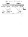
図20は、実施例3に係るタグ管理情報の変化を説明するための説明図である。タグ管理情報90は、出現タグ管理テーブル91、順序管理テーブル92Aからなる。ここでは、出現タグ管理テーブル91や順序管理テーブル92Aの構造を例えばFIFO(Fast In Fast Out)方式(先に入った情報が先に消去される方式)で管理し、情報(タグアドレス)の追加処理や削除処理が必要な場合にはこれまでに記憶していた情報をシフトさせることによって記憶する情報の順番を更新する。 FIG. 20 is an explanatory diagram for explaining a change in tag management information according to the third embodiment. The tag management information 90 includes an appearance tag management table 91 and an order management table 92A. Here, the structure of the appearance tag management table 91 and the order management table 92A is managed by, for example, a FIFO (Fast In Fast Out) method (a method in which previously entered information is erased first), and information (tag address) is added. When processing or deletion processing is necessary, the order of stored information is updated by shifting the information stored so far.
出現タグ管理テーブル91は、タグ1が通信範囲21Pに出現した順番で各タグ1のタグアドレス(8Byte)を記憶する。ここでは、変化前の出現タグ管理テーブル91としてタグ1(E)、タグ1(F)、タグ1(G)、タグ1(H)の順番で各タグ1のタグアドレスを記憶している場合を示している。 The appearance tag management table 91 stores the tag address (8 bytes) of each
順序管理テーブル92Aは、タグ1が通信範囲21Pから通信範囲21Pから消えた順番で各タグ1のタグアドレス(8Byte)を記憶する。ここでは、変化前の順序管理テーブル92Aとしてタグ1(A)、タグ1(B)、タグ1(C)、タグ1(D)の順番で各タグ1のタグアドレスを記憶している場合を示している。 The order management table 92A stores the tag address (8 bytes) of each
順番管理部45が、タグ管理情報90として変化前の出現タグ管理テーブル91、変化前の順序管理テーブル92Aを記憶している状態で、通信範囲21Pからタグ1(E)が消えて新たにタグ1(I)が出現すると、変化後の出現タグ管理テーブル91は、タグ1(F)、タグ1(G)、タグ1(H)、タグ1(I)の順番で各タグ1のタグアドレスを記憶する。また、変化後の順序管理テーブル92Aは、通信範囲21Pから消えたタグ1(E)のタグアドレスを新たに記憶するとともに最初に記憶していた(最も古い)タグ1(A)のタグアドレスを削除する。このとき、変化後の順序管理テーブル92Aは、各タグ1が通信範囲21Pから消えた順番としてタグ1(B)、タグ1(C)、タグ1(D)、タグ1(E)の順番で各タグ1のタグアドレスを記憶する。 In a state where the
順番管理部45は、タグ1の順序に関する情報(順序管理テーブル92Aの更新通知)として順序管理テーブル92Aまたは順序管理テーブル92Aに新たに追加されたタグアドレスをリーダライタ42Aに送信する(ステップS670)。 The
なお、出現タグ管理テーブル91や順序管理テーブル92AのFIFOの深さを通常3段で良いのに対し4段としている理由は、処理の都合上、或いはアンチコリジョンタイミングによっては4つのタグ1を認識できる場合があるからである。 The reason why the FIFO depth of the appearance tag management table 91 and the order management table 92A is usually three levels is set to four levels is that four
なお、順序管理テーブル92Aの最下流のタグアドレスの消去は、新たな情報の追加による押し出しによって消去しても良いし、リーダライタ42A側の処理の完了を受信した後に消去しても良い。 The most downstream tag address in the order management table 92A may be deleted by pushing out by adding new information, or may be deleted after receiving the completion of processing on the reader /
また、本実施例3ではタグ管理情報90が出現タグ管理テーブル91と、順序管理テーブル92Aの2つからなるが、ベルトコンベアの起動時点でタグ1の存在が全くない状態から始めるのであれば、出現タグ管理テーブル91が、順序管理テーブル92Aの機能を兼ねても良い。 Further, in the third embodiment, the tag management information 90 includes the appearance tag management table 91 and the order management table 92A. If the tag management information 90 starts from a state where there is no
また、出現タグ管理テーブル91からタグアドレスを消去する際にはノイズによる一時的な読み取りの失敗を考慮して、タグ1を2回以上読み込むこととしてもよい。また、タグ管理情報90は、リーダライタ41の順番管理部45が記憶する場合に限られず、PC5が記憶することとしてもよい。また、順番管理部45が出現タグ管理テーブル91と順序管理テーブル92Aのいずれか一方を記憶し、他方をPC5が記憶することとしてもよい。 In addition, when deleting the tag address from the appearance tag management table 91, the
図21は、実施例3に係るタグへの書き込み/読み出し処理の手順を示すフローチャートである。リーダライタ42Aの処理を開始し、リーダライタ42Aの通信管理部47は、リーダライタ41から順序管理テーブル92Aの更新通知を受信したか否かを確認する(ステップS700,S710)。 FIG. 21 is a flowchart illustrating a procedure of processing for writing / reading a tag according to the third embodiment. The processing of the reader /
通信管理部47は、リーダライタ41から順序管理テーブル92Aの更新通知を受信すると予め記憶していた順序管理テーブル92Aを更新する(ステップS720)。通信管理部47は、順序管理テーブル92Aに記憶しているタグ1であって読み込み/書き込み処理の完了していないタグ1があるか否かを判断する(ステップS730)。リーダライタ42Aは、読み込み/書き込み処理の完了していないタグ1がある場合、順序管理テーブル92A内の読み込み/書き込み処理の完了していないタグ1において最下位(最下流)のタグ1のアドレスを指定する(ステップS740)。リーダライタ42Aは、例えば実施例1の図6で説明した手順によって、指定したタグアドレスの読み込み/書き込み処理を行なう(ステップS750)。 When the
通信管理部47は、読み込み/書き込み処理を行なったタグ1のタグアドレスを順序管理テーブル92Aから削除する(ステップS760)。通信管理部47は、読み込み/書き込み処理を行なったタグ1のタグアドレスを必要に応じて順番管理部45に通知する(ステップS770)。 The
通信管理部47は、順序管理テーブル92Aに記憶しているタグ1であって読み込み/書き込み処理の完了していないタグ1があるか否かを判断する(ステップS780)。順序管理テーブル92Aに記憶しているタグ1であって読み込み/書き込み処理の完了していないタグ1がある場合(ステップS780、No)、読み込み/書き込み処理の完了していないタグ1がなくなるまでステップS740〜S780の処理を繰り返す。これにより、リーダライタ41は通信範囲21Aから消えていくタグ1の順番でタグ1に読み込み/書き込み処理を行うことが可能となる。 The
なお、実施例3のRFIDシステムにおいては、ベルトコンベアの上流に位置するアンテナ2Pのビームを絞り、ベルトコンベアの下流に位置するアンテナ2Aのビームを広げることによって効率良くタグ1への読み込み/書き込み処理を行うことが可能となる。 In the RFID system of the third embodiment, the beam of the
図22は、ビーム幅を変更したRFIDシステムのシステム構成を示す図である。ベルトコンベアの上流に位置するアンテナ2Pは、順番に流れてくるタグ1のタグアドレスのみを洩れなく読み取ればよいため、アンチコリジョン処理の面からも一度に処理できるタグ1の数は少ない方が良い。したがって、通信可能範囲(L)としてはコリジョンアービトレーションの1ラウンド時間のタグ移動距離(TS)の2倍以上あれば良い。 FIG. 22 is a diagram illustrating a system configuration of an RFID system in which the beam width is changed. Since the
アンテナ2Pのビームを広くすると、多数のタグ1からアンチコリジョン制御で全タグ1を認識し、通信範囲21Pに新たに出現するタグ1、通信範囲21Pから消えていくタグ1を検出する必要がある。したがって、先述したように1ラウンド時間のタグ移動距離(TS)が、通信可能範囲(L)の1/2を超えないことを満たしたうえで、一度に処理できるタグ1の数が少なくなるようアンテナ2Pのビーム幅を狭くする。アンテナ2Pのビームは、タグ1の移動速度やタグ1間の距離等に応じて設定する。 If the beam of the
また、リーダライタ42Aは、ベルトコンベアの下流に位置するアンテナ2Aはタグ1のアドレス情報(タグアドレス)が事前に分かっているため、タグアドレスによってタグ1を直接指定してタグ1にアクセスすることができる。このため、リーダライタ42Aは、コリジョンアービトレーションが不要であり、各タグ1のリードライト処理に専念できる。したがって、アンテナ2Aのビーム幅を広くすることによってタグ1との通信距離(アンテナ2Aと通信できる範囲の長さ)を大きくし、タグ1への書き込み/読み出し処理の処理可能(許容)時間を大きくする。これにより、リーダライタ42Aが行なうタグ1への書き込み/読み出し処理に一時的な余裕度が増す。 The reader /
なお、本実施例3においては、リーダライタ41とリーダライタ42Aを別々の構成として配置しているが、リーダライタ41,42Aを1つの装置で構成してもよい。この場合、1つのリーダライタによってアンテナ2P,2Aの通信制御を行なう。 In the third embodiment, the reader /
また、本実施例3においてはリーダライタ41がリーダライタ42Aへ順序管理テーブル92Aを送信することとしたが、リーダライタ41からPC5を介してリーダライタ42Aへ順序管理テーブル92Aを送信することとしてもよい In the third embodiment, the reader /
このように、下流側のリーダライタ42Aがリーダライタ41から送られる順序管理テーブル92Aに基づいてタグ1への読み込み/書き込み処理を行なうため、リーダライタ42Aではアンチコリジョン処理が不要となる。このため、リーダライタ42Aはアンチコリジョン処理に要する時間をタグ1に対する書込み/読み込み処理に充当することが可能となる。 Thus, since the reader /
このように実施例3によれば、リーダライタ41によってタグ1の流れる順序(通信範囲21Pに入ってくるタグ1の順番等)に関する情報を事前に得ることができるため、リーダライタ42Aは通信範囲21Aから消えていくタグ1の順番でタグ1への読み込み/書き込み処理をすることができる。したがって、リーダライタ42Aはタグ1への読み込み/書き込み処理の処理洩れを減少させることができ、効率良くタグ1への読み込み/書き込み処理を行なうことが可能となる。 As described above, according to the third embodiment, the reader /
また、タグ認識を行なうリーダライタ41のアンテナ2Pのビーム幅を絞ることによって、複数の余計なタグを認識する必要がなく、効率良いタグ認識が可能となる。また、書き込み/読み取り処理を行なうリーダライタ42Aのアンテナ2Aのビーム幅を広げることによって、リーダライタ42Aによる書き込み/読み取り処理の処理余裕度が増加する。 Further, by narrowing the beam width of the
次に、図23および図24を用いてこの発明の実施例4について説明する。実施例4では実施例3のRFIDシステムにおいて、RFIDシステムがタグ1への読み込み/書き込み処理をするリーダライタを複数備える。 Next, Embodiment 4 of the present invention will be described with reference to FIGS. In the fourth embodiment, in the RFID system of the third embodiment, the RFID system includes a plurality of reader / writers that perform read / write processing on the
図23は、実施例4に係るRFIDシステムのシステム構成を示す図である。図23の各構成要素のうち図16に示す実施例3のRFIDシステムと同一機能を達成する構成要素については同一番号を付しており、重複する説明は省略する。 FIG. 23 is a diagram illustrating a system configuration of the RFID system according to the fourth embodiment. Of the components shown in FIG. 23, components that achieve the same functions as those of the RFID system according to the third embodiment shown in FIG. 16 are denoted by the same reference numerals, and redundant description is omitted.
図23に示すようにRFIDシステムは、PC5、リーダライタ41,42B,42C、アンテナ2P,2B,2C、複数の移動対象50、各移動対象50に貼り付けられたタグ1からなる。 As shown in FIG. 23, the RFID system includes a
リーダライタ41は、移動対象50(タグ1)の移動経路51において、リーダライタ42B,42Cより上流側(図面の右側)に配置される。本実施例3においては、リーダライタ41の順番管理部45はリーダライタ42Bに送信するための順序管理テーブル92Bとリーダライタ42Cに送信するための順序管理テーブル92Cを生成する。すなわち、本実施例3においてはタグ管理情報90は、出現タグ管理テーブル91、順序管理テーブル92B,92Cからなる。 The reader /
リーダライタ42B,42Cは、リーダライタ42Aと同様の構成を有しており、それぞれリーダライタ41が生成したタグ管理情報90の順序管理テーブル92B,92Cに従って各タグ1の読み取り/書き込み処理を行なう。順序管理テーブル92B,92Cは、順序管理テーブル92Aと同様の構成を有しており、順序管理テーブル92Bにはリーダライタ42Bが処理するタグ1のタグアドレスが示され、順序管理テーブル92Cにはリーダライタ42Cが処理するタグ1のタグアドレスが示される。アンテナ2Bは、リーダライタ42Bに接続され、通信範囲21Bでタグ1と通信を行う。アンテナ2Cは、リーダライタ42Cに接続され、通信範囲21Cでタグ1と通信を行う。 The reader /
次に、実施例4に係るRFIDシステムの処理手順について説明する。図24は、実施例4に係るタグ移動順序の認識処理の手順を示すフローチャートである。リーダライタ41の順番管理部45は、タグ1の移動順序を示すタグ管理情報90を作成するため、1ラウンドのコリジョンアービトレーションによって認識できるタグ1の全てのアドレスを検出する(ステップS800,S810)。 Next, a processing procedure of the RFID system according to the fourth embodiment will be described. FIG. 24 is a flowchart illustrating a procedure of tag movement order recognition processing according to the fourth embodiment. The
順番管理部45による出現タグ管理テーブル91の更新処理は、前回のサイクルの読み取り結果と、今回の読み取り結果を比較することによって行なう(ステップS820)。順番管理部45は、前回のサイクルの読み取り結果に対して今回の読み取り結果に新規なタグ1が含まれているか否かを判断する(ステップS830)。 The update processing of the appearance tag management table 91 by the
今回の読み取り結果に新規なタグ1が含まれていた場合(ステップS830、Yes)、順番管理部45はこのタグ1のタグアドレスを出現タグ管理テーブル91の最後に追加する(ステップS840)。一方、今回の読み取り結果に新規なタグ1が含まれていない場合(ステップS830、No)、順番管理部45は出現タグ管理テーブル91にタグアドレスの追加を行なわない。 If a
また、順番管理部45は前回のサイクルの読み取り結果に対して今回の読み取り結果で通信範囲21Pから消えたタグ1が含まれているか否かを判断する(ステップS850)。今回の読み取り結果で通信範囲21Pから消えたタグ1が含まれている場合は(ステップS850、Yes)、順番管理部45は消えたタグ1のタグアドレスを順序管理テーブル92B,92Cの何れに記憶させるかを判断するためのフラグが「1」であるか否かを確認する(ステップS860)。 Further, the
ここでのフラグは、通信範囲21Pから消えたタグ1のタグアドレスを順序管理テーブル92Bに記憶させる場合に「1」を示し、消えたタグ1のタグアドレスを順序管理テーブル92Cに記憶させる場合に「0」を示す。 The flag here indicates “1” when the tag address of the
フラグが「1」である場合(ステップS860、Yes)、順番管理部45は通信範囲21Pから消えたタグ1のタグアドレスを順序管理テーブル92Bの最後に追加する(ステップS870)。 When the flag is “1” (step S860, Yes), the
順番管理部45は、タグ1の順序に関する情報(順序管理テーブル92Bの更新通知)として順序管理テーブル92Bまたは順序管理テーブル92Bに新たに追加されたタグアドレスをリーダライタ42Bに送信する(ステップS880)。 The
一方、フラグが「0」である場合(ステップS860、No)、順番管理部45は通信範囲21Pから消えたタグ1のタグアドレスを順序管理テーブル92Cの最後に追加する(ステップS890)。 On the other hand, when the flag is “0” (step S860, No), the
順番管理部45は、タグ1の順序に関する情報(順序管理テーブル92Cの更新通知)として順序管理テーブル92Cまたは順序管理テーブル92Cに新たに追加されたタグアドレスをリーダライタ42Cに送信する(ステップS900)。 The
順序管理テーブル92B,92Cの更新通知の後、フラグを反転させる(ステップS910)。ここでのフラグの反転は、フラグが「1」であった場合はフラグを「0」にし、フラグが「0」であった場合はフラグを「1」にする。 After the update notification of the order management tables 92B and 92C, the flag is reversed (step S910). The inversion of the flag here is to set the flag to “0” when the flag is “1” and to set the flag to “1” when the flag is “0”.
これにより、出現タグ管理テーブル91にタグ1(A)、タグ1(B)、タグ1(C)、タグ1(D)、タグ1(E)、タグ1(F)の順番で各タグ1のタグアドレスが記憶されている場合、順序管理テーブル92Bには例えばタグ1(A)、タグ1(C)、タグ1(E)の順番で各タグ1のタグアドレスが登録(記憶)され、順序管理テーブル92Bにはタグ1(B)、タグ1(D)、タグ1(F)の順番で各タグ1のタグアドレスが登録される。これにより、タグ1の処理権(書き込み/読み出し処理)は下流に配置されている2つのリーダライタ42B,42Cに対して交互に与えられることになる。 Thereby, each
ステップS850において、今回の読み取り結果で通信範囲21Pから消えたタグ1が含まれていない場合は、順序管理テーブル92B,92Cにタグアドレスの追加を行なわない。リーダライタ42B,42Cは、実施例3の図21で説明したリーダライタ42Aと同様の処理手順によってタグ1への書き込み/読み出し処理を行なうため、その説明は省略する。 In step S850, if the
なお、本実施例4においては、タグ1への書き込み/読み出し処理を行なうリーダライタ(下流側)をリーダライタ42B,42Cの2つとしたが、タグ1への書き込み/読み出し処理を行なうリーダライタは3つ以上であってもよい。タグ1への書き込み/読み出し処理を行なうリーダライタが3つ以上である場合も、リーダライタ41は書き込み/読み出し処理を行なうリーダライタ毎に順序管理テーブルを作成する。 In the fourth embodiment, the reader / writer (downstream side) that performs the writing / reading process on the
このように、RFIDシステムが複数のリーダライタ42B,42Cを備えているため、複数のタグ1の書き込み/読み出し処理を複数のリーダライタ42B,42Cで分散することが可能となる。 As described above, since the RFID system includes the plurality of reader /
このように実施例4によれば、複数のタグ1の書き込み/読み出し処理を複数のリーダライタ42B,42Cで分散して処理することが可能となり、タグ1に対する書き込み/読み出し処理の負荷分散を行なうことが可能となる。したがって、RFIDシステムにおいてタグ1の移動を高速化することが可能となる。 As described above, according to the fourth embodiment, writing / reading processing of a plurality of
次に、図25〜図26を用いてこの発明の実施例5について説明する。実施例5ではRFIDシステムが複数のリーダライタを備えるとともに、各リーダライタを所定の間隔で配置させる。そして、各リーダライタがそれぞれ所定のタグ1に対してタグ認識処理や読み込み/書き込み処理をする。RFIDシステムは、刻々と流れてくるタグ1の流れと複数のリーダライタのアクセス処理を同期化してタイムスロット化することによって複数のリーダライタ(アンテナ)で交互に処理を担い、リーダライタの負荷を分散する。 Next, a fifth embodiment of the present invention will be described with reference to FIGS. In the fifth embodiment, the RFID system includes a plurality of reader / writers and the reader / writers are arranged at predetermined intervals. Each reader / writer performs a tag recognition process and a read / write process on a
図25は、実施例5に係るRFIDシステムのシステム構成を示す図である。図25の各構成要素のうち図16に示す実施例3のRFIDシステムと同一機能を達成する構成要素については同一番号を付しており、重複する説明は省略する。 FIG. 25 is a diagram illustrating a system configuration of the RFID system according to the fifth embodiment. Of the constituent elements in FIG. 25, constituent elements that achieve the same functions as those of the RFID system of the third embodiment shown in FIG. 16 are denoted by the same reference numerals, and redundant description is omitted.
図25に示すようにRFIDシステムは、PC5、リーダライタ42D,42E、アンテナ2D,2E、複数の移動対象50、各移動対象50に貼り付けられたタグ1からなる。リーダライタ42Dがリーダライタ42Eよりも上流側に配置されている。 As shown in FIG. 25, the RFID system includes a
リーダライタ42D,42Eは、タグ1の移動速度やタグ1間の間隔(距離)に応じた所定の距離間隔で配置される。リーダライタ42D,42Eは、ベルトコンベア上を所定の間隔で順番に流れてくるタグ1をそれぞれ交互(1つおき)に処理(タグ認識、書き込み/読み出し)する。 The reader /
具体的には、リーダライタ42Dとリーダライタ42Eをベルトコンベアに沿って配置させ、リーダライタ42Dの制御部19はアンテナ2Dには通信範囲21DでタグA系のタグ(タグA1,A2,A3・・・Ax(xは自然数))のみを処理させ、リーダライタ42Eの制御部19はアンテナ2Eには通信範囲21EでタグB系のタグ(タグB1,B2,B3・・・Bxのみを処理させるようにする。 Specifically, the reader /
通信範囲21Dには、同時に複数のA系のタグ1が移動してこないよう、タグ1の移動速度、タグ1間の距離、通信範囲21Dの範囲(距離)等を設定しておく。また、通信範囲21Eには、同時に複数のB系のタグ1が移動してこないよう、タグ1の移動速度、タグ1間の距離、通信範囲21Eの範囲等を設定しておく。 In the communication range 21D, the moving speed of the
リーダライタ42Dには、所定の時間間隔で通信範囲21Dに侵入してくるタグ1(A系)のみを処理し、所定の時間間隔で通信範囲21Dに侵入してくるタグ1(B系)を無視するよう設定しておく。ここでの時間間隔は、タグ1の移動速度、タグ1間の距離、通信範囲21Dの範囲に基づいて設定される。 The reader /
また、リーダライタ42Eには、所定の時間間隔で通信範囲21Eに侵入してくるタグ1(B系)のみを処理し、所定の時間間隔で通信範囲21Eに侵入してくるタグ1(A系)を無視するよう設定しておく。ここでの時間間隔は、タグ1の移動速度、タグ1間の距離、通信範囲21Eの範囲に基づいて設定される。 The reader / writer 42E processes only the tag 1 (B system) that enters the communication range 21E at a predetermined time interval, and the tag 1 (A system) that enters the communication range 21E at a predetermined time interval. ) Is ignored. The time interval here is set based on the moving speed of the
図26は、各リーダライタが処理するタグを説明するための説明図である。図26に示すように、リーダライタ42Dは時間T0でタグA1を処理した後、タグB1を無視して時間T2でタグA2を処理する。リーダライタ42Dは、時間T1においてタグA1の処理を続けていてもよい。また、リーダライタ42DはタグA2を処理した後、タグB2を無視して時間T4でタグA3を処理する。リーダライタ42Dは、時間T3においてタグA2の処理を続けていてもよい。 FIG. 26 is an explanatory diagram for explaining a tag processed by each reader / writer. As shown in FIG. 26, after the reader /
リーダライタ42Eは、時間T0より前の処理において、タグA1,A2を無視してタグB1,B2の処理を行う(図示せず)。リーダライタ42Eは時間T0でタグB3を処理した後、タグA4を無視して時間T2でタグB4を処理する。リーダライタ42Eは、時間T1においてタグB3の処理を続けていてもよい。また、リーダライタ42EはタグB4を処理した後、タグA5を無視して時間T4でタグB5を処理する。リーダライタ42Eは、時間T2においてタグB4の処理を続けていてもよい。この後、リーダライタ42Dは、リーダライタ42Eが無視したタグA4,A5を処理する。 In the process before time T0, the reader / writer 42E ignores the tags A1 and A2 and processes the tags B1 and B2 (not shown). The reader / writer 42E processes the tag B3 at time T0, ignores the tag A4, and processes the tag B4 at time T2. The reader / writer 42E may continue processing the tag B3 at time T1. Further, after processing the tag B4, the reader / writer 42E ignores the tag A5 and processes the tag B5 at time T4. The reader / writer 42E may continue processing the tag B4 at time T2. Thereafter, the reader /
これにより、各リーダライタ42D,42Eが各タグ1の処理に費やすことができる時間は、リーダライタが1つの時に比べて2倍となる。このことは、タグ1に対する処理時間が増えるためタグ1の移動の高速化が可能になることを意味している。 As a result, the time that each reader /
なお、本実施例4ではRFIDシステムがリーダライタ42D,42Eを2つ備える構成としているが、RFIDシステムはリーダライタを3つ以上で構成してもよい。これにより、RFIDシステムがリーダライタ42D,42Eを2つ備える構成の場合よりもリーダライタの処理分散化が可能となり、タグ1の移動(ベルトコンベア)の高速化が可能となる。なお、リーダライタ42D,42Eは、タグ1への書き込み/読み出し処理だけを行ってもよいし、タグ1のタグ認識処理とタグ1への書き込み/読み出し処理の両方を行ってもよい。 In the fourth embodiment, the RFID system includes two reader /
このように、RFIDシステムが複数のリーダライタ42D,42Eを備えているため、複数のタグ1の書き込み/読み出し処理を複数のリーダライタ42D,42Eで分散することが可能となる。 As described above, since the RFID system includes the plurality of reader /
このように実施例5によれば、複数のタグ1を複数のリーダライタ42D,42Eで分散して処理することが可能となり、タグ1に対する処理の負荷分散を行なうことが可能となる。したがって、RFIDシステムにおいてタグ1の移動を高速化することが可能となる。 As described above, according to the fifth embodiment, a plurality of
なお、RFIDシステムとしては、実施例1から実施例5に示したRFIDシステムに限られず、実施例1から実施例5に示したRFIDシステムを2つ以上組み合せた構成のRFIDシステムによってタグ認識処理やタグへの書き込み/読み出し処理を行なってもよい。 Note that the RFID system is not limited to the RFID system shown in the first to fifth embodiments, and the tag recognition process or the like is performed by the RFID system having a configuration in which two or more RFID systems shown in the first to fifth embodiments are combined. A tag writing / reading process may be performed.
以上のように、本発明にかかるリーダライタおよびRFIDシステムは、移動する無線タグへの読み取り/書き込み処理に適している。 As described above, the reader / writer and the RFID system according to the present invention are suitable for reading / writing processing on a moving wireless tag.
1,A1〜Ax,B1〜Bx タグ
2A〜2E,2P,2R,2W〜2Z,94 アンテナ
5 PC
10,30,41,42A〜42E,93 リーダライタ
11 MPU
12 送信部
13 受信部
14 信号分配合成部
19 制御部
20 通信可能エリア
21A〜21E,21P,21R,21X〜21Z,P1,P2,Pn 通信範囲
31 回転制御部
45 順番管理部
47 通信管理部
50 移動対象
51 移動経路
90 タグ管理情報
91 出現タグ管理テーブル
92A〜92C 順序管理テーブル
140 LPF
H1〜H3 ハイブリッド1, A1-Ax, B1-
10, 30, 41, 42A to 42E, 93 Reader /
DESCRIPTION OF
H1-H3 hybrid
Claims (7)
Translated fromJapanese各アンテナの通信範囲が前記無線タグの所定の移動経路に沿って連続するよう配置される複数のアンテナと、
前記無線タグへ送信する信号を前記複数のアンテナに分配するとともに、前記複数のアンテナが前記無線タグから受信した信号を合成する信号処理部と、
を備えることを特徴とするリーダライタ。In a reader / writer that writes and reads information on a wireless tag,
A plurality of antennas arranged such that the communication range of each antenna is continuous along a predetermined movement path of the wireless tag;
A signal processing unit that distributes signals to be transmitted to the wireless tag to the plurality of antennas, and combines the signals received by the plurality of antennas from the wireless tag;
A reader / writer characterized by comprising:
前記アンテナの通信範囲が前記無線タグの移動位置に追従するよう前記アンテナの向く方向を制御する方向制御部を備えることを特徴とするリーダライタ。In a reader / writer that writes and reads information to and from a wireless tag via an antenna,
A reader / writer, comprising: a direction control unit that controls a direction in which the antenna faces so that a communication range of the antenna follows a moving position of the wireless tag.
前記無線タグから前記識別情報を受信するとともに、前記識別情報に基づいて前記無線タグの移動の順番に関する順序情報を生成する順序情報生成部を備える第1のリーダライタと、
前記順序情報生成部からの順序情報に基づいて、前記無線タグに情報の書き込みおよび読み出しを行なう通信部を備える第2のリーダライタと、
を備えることを特徴とするRFIDシステム。In an RFID system that receives identification information of a wireless tag from a wireless tag, and writes and reads information to and from the wireless tag based on the identification information.
A first reader / writer provided with an order information generating unit that receives the identification information from the wireless tag and generates order information related to the order of movement of the wireless tag based on the identification information;
A second reader / writer including a communication unit that writes and reads information to and from the wireless tag based on the order information from the order information generation unit;
An RFID system comprising:
前記第1のリーダライタが備える前記順序情報生成部は、複数からなる前記第2のリーダライタ毎に前記第2のリーダライタに対応した前記順序情報を生成することを特徴とする請求項3〜5のいずれか1つに記載のRFIDシステム。The second reader / writer is composed of a plurality of
The order information generation unit included in the first reader / writer generates the order information corresponding to the second reader / writer for each of the plurality of second reader / writers. The RFID system according to any one of 5.
前記各リーダライタが複数の前記無線タグに対し分散して情報の書き込みおよび読み出しを行なえるよう、前記各リーダライタを前記無線タグの移動速度、前記無線タグ間の距離および前記各リーダライタが前記無線タグと通信を行う通信範囲に応じた間隔で配置することを特徴とするRFIDシステム。In the RFID system having a plurality of reader / writers that receive identification information of the wireless tag from the wireless tag and write and read information on the wireless tag based on the identification information.
The reader / writer is configured so that each reader / writer can read and write information in a distributed manner with respect to a plurality of the wireless tags. An RFID system, which is arranged at intervals corresponding to a communication range for communicating with a wireless tag.
Priority Applications (9)
| Application Number | Priority Date | Filing Date | Title |
|---|---|---|---|
| JP2004289289AJP2006106897A (en) | 2004-09-30 | 2004-09-30 | Reader / writer and RFID system |
| US11/042,543US20060077039A1 (en) | 2004-09-30 | 2005-01-26 | Reader/writer and RFID system |
| EP05250436AEP1643413A3 (en) | 2004-09-30 | 2005-01-27 | Reader/writer and RFID system |
| EP09167824AEP2133815A1 (en) | 2004-09-30 | 2005-01-27 | Reader/writer and RFID system |
| EP09167831AEP2133814A1 (en) | 2004-09-30 | 2005-01-27 | Reader/writer and RFID system |
| KR1020050015208AKR100683013B1 (en) | 2004-09-30 | 2005-02-24 | Reader / Writer and RFID System |
| CNA2009101281726ACN101499125A (en) | 2004-09-30 | 2005-02-28 | Reader/writer and RFID system |
| CNB200510051146XACN100399345C (en) | 2004-09-30 | 2005-02-28 | Read/write device |
| CNB2007101090946ACN100570626C (en) | 2004-09-30 | 2005-02-28 | Reader/Writer and RFID System |
Applications Claiming Priority (1)
| Application Number | Priority Date | Filing Date | Title |
|---|---|---|---|
| JP2004289289AJP2006106897A (en) | 2004-09-30 | 2004-09-30 | Reader / writer and RFID system |
Publications (1)
| Publication Number | Publication Date |
|---|---|
| JP2006106897Atrue JP2006106897A (en) | 2006-04-20 |
Family
ID=35615589
Family Applications (1)
| Application Number | Title | Priority Date | Filing Date |
|---|---|---|---|
| JP2004289289AWithdrawnJP2006106897A (en) | 2004-09-30 | 2004-09-30 | Reader / writer and RFID system |
Country Status (5)
| Country | Link |
|---|---|
| US (1) | US20060077039A1 (en) |
| EP (3) | EP2133814A1 (en) |
| JP (1) | JP2006106897A (en) |
| KR (1) | KR100683013B1 (en) |
| CN (3) | CN101499125A (en) |
Cited By (15)
| Publication number | Priority date | Publication date | Assignee | Title |
|---|---|---|---|---|
| WO2008035433A1 (en)* | 2006-09-22 | 2008-03-27 | Fujitsu Limited | Mobile unit and control method |
| WO2008084837A1 (en)* | 2007-01-11 | 2008-07-17 | Brother Kogyo Kabushiki Kaisha | Tag label creation device and radio circuit element cartridge |
| WO2008117676A1 (en)* | 2007-03-27 | 2008-10-02 | Brother Kogyo Kabushiki Kaisha | Wireless tag information reader |
| JP2009033517A (en)* | 2007-07-27 | 2009-02-12 | Omron Corp | Noncontact communication device and noncontact communication method |
| JP2009043253A (en)* | 2007-07-30 | 2009-02-26 | Nec (China) Co Ltd | Tag identification system, tag reader, and tag sequence determination method |
| JP2010141606A (en)* | 2008-12-11 | 2010-06-24 | Nippon Telegr & Teleph Corp <Ntt> | Rfid system, and method, apparatus and program for control in the system |
| KR101058447B1 (en) | 2007-01-24 | 2011-08-24 | 홍콩 폴리테크닉 유니버시티 | Apparatus and method for identifying target movement and location by RFID device |
| JP2011192003A (en)* | 2010-03-15 | 2011-09-29 | Toppan Forms Co Ltd | RF-ID media inspection system |
| JP2012073245A (en)* | 2010-09-29 | 2012-04-12 | Fujitsu Ltd | Measuring method and device for radio frequency identifying tag positions |
| US8674852B2 (en) | 2009-01-19 | 2014-03-18 | Airbus Operations Sas | Method and system for displaying symbologies on an aircraft |
| JP2017059954A (en)* | 2015-09-15 | 2017-03-23 | 株式会社東芝 | Communication device, communication method, and program |
| JP2017130129A (en)* | 2016-01-22 | 2017-07-27 | 富士通フロンテック株式会社 | RFID tag issuing system and RFID tag issuing method |
| JP2019052029A (en)* | 2017-09-15 | 2019-04-04 | 東芝テック株式会社 | Paratus and method for reading |
| US11436461B2 (en) | 2005-02-22 | 2022-09-06 | Kepler Computing Inc. | Mobile phone with magnetic card emulation |
| WO2024204212A1 (en)* | 2023-03-27 | 2024-10-03 | Toppanエッジ株式会社 | Information reading method |
Families Citing this family (75)
| Publication number | Priority date | Publication date | Assignee | Title |
|---|---|---|---|---|
| KR100686384B1 (en)* | 2005-08-20 | 2007-02-22 | (주)네스랩 | Space collision avoidance method and space collision prevention of RFID reader system |
| JP4123195B2 (en)* | 2004-06-22 | 2008-07-23 | オムロン株式会社 | Tag communication device, tag communication device control method, tag communication control program, and tag communication management system |
| US20060208896A1 (en)* | 2005-03-04 | 2006-09-21 | Mason Robert C | Use of radio frequency identification for coupling input and output modules |
| GB0505452D0 (en)* | 2005-03-17 | 2005-04-20 | Aea Technology Plc | Door control system |
| JP5027398B2 (en) | 2005-09-27 | 2012-09-19 | ルネサスエレクトロニクス株式会社 | IC tag identification method |
| US7504950B2 (en)* | 2005-11-30 | 2009-03-17 | Zih Corp. | System and method for continuous RFID encoding |
| JP4120843B2 (en)* | 2006-05-10 | 2008-07-16 | オムロン株式会社 | Tag communication device, tag moving direction detection system, and tag moving direction detection method |
| JP4219942B2 (en)* | 2006-05-19 | 2009-02-04 | 株式会社日立製作所 | RFID system |
| KR100728306B1 (en)* | 2006-06-19 | 2007-06-13 | 학교법인 포항공과대학교 | Tag Collision Avoidance in Radio Frequency Identification System |
| US7535338B2 (en)* | 2006-06-27 | 2009-05-19 | Sensormatic Electronics Corporation | Wireless synchronized operation of pulsed EAS systems |
| US7920046B1 (en) | 2006-07-21 | 2011-04-05 | Impinj, Inc. | RFID readers and systems initializing after antenna switch and methods |
| US8120494B1 (en) | 2006-07-21 | 2012-02-21 | Impinj, Inc. | RFID readers and systems with antenna switching upon detecting too few tags and methods |
| KR100829866B1 (en)* | 2006-07-26 | 2008-05-16 | 한국전자통신연구원 | Multiple Moving Tag Identification Method with Multiple Reader |
| JP4983199B2 (en)* | 2006-10-23 | 2012-07-25 | 富士通株式会社 | COMMUNICATION METHOD, COMMUNICATION SYSTEM, ACCESS CONTROL DEVICE, AND COMPUTER PROGRAM |
| US20080174406A1 (en)* | 2006-10-27 | 2008-07-24 | University Of Pittsburgh-Of The Commonwealth System Of Higher Education | Transponder systems |
| JP4788969B2 (en)* | 2006-12-11 | 2011-10-05 | ブラザー工業株式会社 | Wireless tag information communication device |
| US8120463B2 (en)* | 2007-01-04 | 2012-02-21 | Lockheed Martin Corporation | RFID protocol for improved tag-reader communications integrity |
| JP4452286B2 (en)* | 2007-03-05 | 2010-04-21 | 株式会社日立製作所 | Tag detection system, moving object detection method, and entrance / exit management system |
| JP5355936B2 (en)* | 2007-06-28 | 2013-11-27 | 日本信号株式会社 | Reader / writer and article sorting system |
| CN101359358B (en)* | 2007-07-30 | 2013-01-02 | 日电(中国)有限公司 | Label recognizing system, label accessing device and label sposition determining method |
| JP5058260B2 (en)* | 2007-08-09 | 2012-10-24 | 三菱電機株式会社 | Inspection system |
| JP2009069983A (en)* | 2007-09-11 | 2009-04-02 | Hitachi Ltd | RF tag R / W (reader / writer) control method and control apparatus |
| US9741027B2 (en) | 2007-12-14 | 2017-08-22 | Tyfone, Inc. | Memory card based contactless devices |
| US7931205B2 (en)* | 2008-02-04 | 2011-04-26 | Avery Dennison Corporation | Printer with integrated RFID data collector |
| JP2009230469A (en)* | 2008-03-24 | 2009-10-08 | Kyocera Mita Corp | Operation device and image forming apparatus |
| JP5186971B2 (en)* | 2008-03-24 | 2013-04-24 | 富士通株式会社 | Wireless communication system and wireless communication device |
| DE102008025975A1 (en)* | 2008-05-30 | 2009-12-03 | Herbert Kannegiesser Gmbh | Method and device for sorting garments hanging on transporting hangers |
| US8451122B2 (en) | 2008-08-08 | 2013-05-28 | Tyfone, Inc. | Smartcard performance enhancement circuits and systems |
| US12147863B2 (en) | 2008-08-08 | 2024-11-19 | Icashe, Inc. | Method and apparatus for transmitting data via NFC for mobile applications including mobile payments and ticketing |
| US7961101B2 (en) | 2008-08-08 | 2011-06-14 | Tyfone, Inc. | Small RFID card with integrated inductive element |
| US20100033310A1 (en)* | 2008-08-08 | 2010-02-11 | Narendra Siva G | Power negotation for small rfid card |
| CN101661549B (en)* | 2008-08-29 | 2011-09-21 | 华为技术有限公司 | Electronic tag and response method, electronic tag identification method, device and system |
| TWI420398B (en) | 2009-02-24 | 2013-12-21 | Tyfone Inc | Contactless device with miniaturized antenna |
| GB2473236B (en)* | 2009-09-04 | 2015-01-07 | Hitachi Ltd | Determining a path of a wireless tag |
| CN101795149B (en)* | 2009-11-13 | 2013-10-30 | 深圳市科陆电子科技股份有限公司 | Antenna classification extension method and system |
| US8487746B2 (en)* | 2009-11-17 | 2013-07-16 | Christopher Todd Gordon | Jump rope training apparatus, method, and system |
| DE102010020531A1 (en) | 2010-05-14 | 2011-11-17 | Sick Ag | Radio frequency identification reader for identifying e.g. goods in parcel sender, of airport, has evaluation unit detecting whether transponder moves on conveyor or by reading portal based on receiving intensity of signals and angles |
| CN101853011A (en)* | 2010-05-26 | 2010-10-06 | 山东莱芜煤矿机械有限公司 | Quickly ration loading system |
| CN101944186A (en)* | 2010-10-08 | 2011-01-12 | 耿直 | Reading and writing method of high-speed moving RFID (Radio Frequency Identification Devices) and high-speed RFID reader-writer |
| CN102024136B (en)* | 2010-12-10 | 2015-05-20 | 中兴通讯股份有限公司 | Method and device for identifying vehicle orders |
| CN102609738A (en)* | 2011-01-25 | 2012-07-25 | 上海互惠信息技术有限公司 | RFID (radio frequency identification device) multi-antenna reader-writer |
| CA2927162C (en)* | 2011-02-17 | 2020-10-20 | National Oilwell Varco, L.P. | System and method for tracking pipe activity on a rig |
| ES2388263B1 (en)* | 2011-03-14 | 2013-09-02 | Atem Nuevas Tecnologias S L | LUGGAGE TRACKING SYSTEM IN AIR TRAFFIC. |
| US10013588B2 (en)* | 2011-08-17 | 2018-07-03 | Hand Held Products, Inc. | Encoded information reading terminal with multi-directional antenna |
| CN102354361A (en)* | 2011-09-13 | 2012-02-15 | 魏中海 | Method for identifying travelling direction by using active RFID (radio frequency identification device) and RFID system |
| CN103164672B (en)* | 2011-12-14 | 2016-02-03 | 中国钢铁股份有限公司 | Radio Frequency Identification Tag Grouping System |
| CN103177271A (en)* | 2011-12-20 | 2013-06-26 | 国民技术股份有限公司 | Electronic tag read-write device, system and method |
| KR101828308B1 (en)* | 2012-07-03 | 2018-02-12 | 삼성전자 주식회사 | Antenna Control System And Portable Device including the same, and Antenna Control Method thereof |
| CN102820519A (en)* | 2012-08-03 | 2012-12-12 | 上海真灼电子技术有限公司 | Antenna system of RFID reader |
| CN103632113A (en)* | 2012-08-22 | 2014-03-12 | 无锡阿法迪科技有限公司 | RFID read-write equipment having radio data receiving-transmitting function |
| DE202013004511U1 (en)* | 2013-05-15 | 2014-08-18 | Checkpoint Systems, Inc. | System for writing RFID transponders |
| KR101586346B1 (en)* | 2013-05-16 | 2016-01-18 | (주)유니콤티디 | Magnetic field signal transmission system |
| CN103473573B (en)* | 2013-08-05 | 2016-06-29 | 浙江工业大学 | The judgement of wandering public bicycles and method for tracing |
| CN103885398A (en)* | 2014-01-26 | 2014-06-25 | 上海挚连科技有限公司 | Commodity and environment monitoring system |
| CN104143106B (en)* | 2014-07-03 | 2018-01-09 | 深圳麦格米特电气股份有限公司 | A kind of antenna system of track traffic electronic tag automatic identification |
| CN104143107B (en)* | 2014-07-03 | 2017-12-15 | 深圳麦格米特电气股份有限公司 | A kind of track vehicle wheel tracing system |
| NL2013640B1 (en) | 2014-10-15 | 2016-10-04 | N V Nederlandsche Apparatenfabriek Nedap | Updating animal management labels. |
| CN104678953B (en)* | 2015-01-23 | 2017-08-18 | 深圳市捷佳伟创新能源装备股份有限公司 | A kind of graphite boat identifying system and method produced for silicon chip |
| CN104850874B (en)* | 2015-04-10 | 2018-10-02 | 上海十贝电子科技有限公司 | The precise positioning method and system of single vector reader |
| US11348428B2 (en)* | 2020-03-12 | 2022-05-31 | Sam Heidari | System and methods for identifying a subject through device-free and device-oriented sensing technologies |
| DE102016209583A1 (en) | 2016-06-01 | 2017-12-21 | Phoenix Contact Gmbh & Co. Kg | Production plant for producing a plurality of articles and methods for controlling and / or monitoring the production plant |
| CN106159463B (en)* | 2016-08-19 | 2023-03-24 | 杭州潮盛科技有限公司 | Antenna and reader |
| US10990868B2 (en)* | 2017-06-20 | 2021-04-27 | Hp Indigo B.V. | RFID device programming |
| JP7119763B2 (en)* | 2018-08-22 | 2022-08-17 | オムロン株式会社 | Manufacturing equipment system, manufacturing equipment, and manufacturing method |
| JP7182950B2 (en) | 2018-08-22 | 2022-12-05 | 東芝テック株式会社 | Management device and management system |
| CN109460688B (en)* | 2018-09-27 | 2021-11-09 | 威海北洋光电信息技术股份公司 | Three-dimensional settlement channel device based on delta-shaped antenna and using method thereof |
| EP3999994B1 (en)* | 2019-07-15 | 2024-03-27 | Avery Dennison Retail Information Services LLC | Method for missed item recovery in rfid tunnel environments |
| JP7321855B2 (en) | 2019-09-13 | 2023-08-07 | 東芝テック株式会社 | Wireless tag reader and wireless tag reading method |
| DE202020103986U1 (en)* | 2020-07-09 | 2020-07-22 | KEMAS Gesellschaft für Elektronik, Elektromechanik, Mechanik und Systeme mbH | Detection device |
| KR102441525B1 (en)* | 2020-08-31 | 2022-09-07 | (주)대원실업사 | Articles sorting system based on rfid |
| JP7724109B2 (en)* | 2021-09-01 | 2025-08-15 | 東芝テック株式会社 | Tag communication device and information processing program |
| CN113791383A (en)* | 2021-10-15 | 2021-12-14 | 郑州轻工业大学 | Combined double-anchor-point positioning method based on ultra-wideband ranging |
| CN120380479A (en)* | 2022-11-29 | 2025-07-25 | 艾利丹尼森零售信息服务有限公司 | Radio frequency identification reader system and method |
| US20240346268A1 (en)* | 2023-04-13 | 2024-10-17 | Bruce Walter Wilkinson | Session Control Broadcaster for RFID Systems |
| CN118247873B (en)* | 2024-03-22 | 2025-01-07 | 厦门纵行信息科技有限公司 | Regional pass detection method and system based on wide area network |
Family Cites Families (34)
| Publication number | Priority date | Publication date | Assignee | Title |
|---|---|---|---|---|
| CN86101893A (en)* | 1985-02-28 | 1986-11-05 | 佳能株式会社 | data communication equipment |
| US4951140A (en)* | 1988-02-22 | 1990-08-21 | Kabushiki Kaisha Toshiba | Image encoding apparatus |
| JP3160305B2 (en)* | 1991-03-30 | 2001-04-25 | 株式会社東芝 | Road toll collection system, road toll collection method, and wireless device |
| DE69334088T2 (en)* | 1992-06-25 | 2007-06-21 | Denso Corp., Kariya | System for identifying moving objects |
| JP3158790B2 (en)* | 1993-07-14 | 2001-04-23 | 株式会社デンソー | Position determination device |
| US6798834B1 (en)* | 1996-08-15 | 2004-09-28 | Mitsubishi Denki Kabushiki Kaisha | Image coding apparatus with segment classification and segmentation-type motion prediction circuit |
| US5517194A (en)* | 1994-02-10 | 1996-05-14 | Racom Systems, Inc. | Passive RF transponder and method |
| US5694139A (en)* | 1994-06-28 | 1997-12-02 | Sony Corporation | Short-distance communication antenna and methods of manufacturing and using the short-distance communication antenna |
| US5805733A (en)* | 1994-12-12 | 1998-09-08 | Apple Computer, Inc. | Method and system for detecting scenes and summarizing video sequences |
| US5649296A (en)* | 1995-06-19 | 1997-07-15 | Lucent Technologies Inc. | Full duplex modulated backscatter system |
| US6384712B1 (en)* | 1997-12-19 | 2002-05-07 | Intermec Ip Corp. | Apparatus, system, and method for communication between multiple base stations and radio frequency (RF) tags |
| DE29800833U1 (en)* | 1998-01-19 | 1998-04-16 | Moba Mobile Automation Gmbh Wa | Device for identifying an object on a conveyor belt |
| DE19824528C1 (en)* | 1998-06-02 | 1999-11-25 | Anatoli Stobbe | Transponder detection method e.g. for security tags, in region divided into at least two cells |
| JP4091200B2 (en) | 1999-03-01 | 2008-05-28 | 横浜ゴム株式会社 | Transponder access method and transponder system |
| FR2794550A1 (en)* | 1999-06-04 | 2000-12-08 | Gemplus Card Int | Automatic identification system for laundered garments on moving conveyor, has electronic label in each garment and moving antenna |
| JP2001014562A (en)* | 1999-07-02 | 2001-01-19 | Star Micronics Co Ltd | Crime prevention tag equipment |
| EP1734461A2 (en)* | 1999-07-12 | 2006-12-20 | Matsushita Electric Industrial Co., Ltd. | Mobile body discrimination apparatus for rapidly acquiring respective data sets transmitted through modulation of reflected radio waves by transponders which are within a communication region of an interrogator apparatus |
| US6539099B1 (en)* | 1999-08-30 | 2003-03-25 | Electric Planet | System and method for visual chat |
| SE9904683L (en)* | 1999-12-17 | 2001-06-18 | Ericsson Telefon Ab L M | Method and system for establishing a short-range radio connection |
| DE10028077A1 (en)* | 2000-06-07 | 2001-12-13 | Siemens Ag | Antenna system with two antennas for read write device for data transmission |
| US6754373B1 (en)* | 2000-07-14 | 2004-06-22 | International Business Machines Corporation | System and method for microphone activation using visual speech cues |
| JP3788211B2 (en) | 2000-07-21 | 2006-06-21 | 株式会社日立製作所 | Data reader / writer and information retrieval and article delivery system |
| DE10056176C1 (en)* | 2000-11-13 | 2002-10-10 | Moba Mobile Automation Gmbh | Transponder reader has one or other antenna arrangement active at defined time and device for detuning inactive antenna so that it is not tuned to its working resonant frequency |
| US6766042B2 (en)* | 2001-04-26 | 2004-07-20 | Memphis Eye & Contact Associates | System to automatically detect eye corneal striae |
| US6703935B1 (en)* | 2001-05-14 | 2004-03-09 | Amerasia International Technology, Inc. | Antenna arrangement for RFID smart tags |
| US7084739B2 (en)* | 2002-06-28 | 2006-08-01 | Brother Kogyo Kabushiki Kaisha | Communication system, and interrogator and transponder for the system |
| CN100576766C (en)* | 2002-09-04 | 2009-12-30 | 杨晓晖 | Method and arrangement for an antenna system for electronic article surveillance |
| US20040070503A1 (en)* | 2002-10-10 | 2004-04-15 | Brian Monahan | Flexible RFID antenna panel and system |
| US6970088B2 (en)* | 2002-10-17 | 2005-11-29 | Compex, Inc. | Method for tracking and processing passengers and their transported articles |
| US20050134449A1 (en)* | 2003-12-18 | 2005-06-23 | Intel Corporation | Two stage radio frequency identification |
| US7420458B1 (en)* | 2004-01-20 | 2008-09-02 | Charles A. Eldering | Secondary card reader |
| US20050280508A1 (en)* | 2004-02-24 | 2005-12-22 | Jim Mravca | System and method for controlling range of successful interrogation by RFID interrogation device |
| DE102004035621A1 (en)* | 2004-07-22 | 2006-03-16 | Feig Electronic Gmbh | Antenna arrangement for large coherent detection areas |
| US7432874B2 (en)* | 2004-07-22 | 2008-10-07 | Feig Electronic Gmbh | Antenna array |
- 2004
- 2004-09-30JPJP2004289289Apatent/JP2006106897A/ennot_activeWithdrawn
- 2005
- 2005-01-26USUS11/042,543patent/US20060077039A1/ennot_activeAbandoned
- 2005-01-27EPEP09167831Apatent/EP2133814A1/ennot_activeWithdrawn
- 2005-01-27EPEP09167824Apatent/EP2133815A1/ennot_activeWithdrawn
- 2005-01-27EPEP05250436Apatent/EP1643413A3/ennot_activeWithdrawn
- 2005-02-24KRKR1020050015208Apatent/KR100683013B1/ennot_activeExpired - Fee Related
- 2005-02-28CNCNA2009101281726Apatent/CN101499125A/enactivePending
- 2005-02-28CNCNB2007101090946Apatent/CN100570626C/ennot_activeExpired - Fee Related
- 2005-02-28CNCNB200510051146XApatent/CN100399345C/ennot_activeExpired - Fee Related
Cited By (17)
| Publication number | Priority date | Publication date | Assignee | Title |
|---|---|---|---|---|
| US11436461B2 (en) | 2005-02-22 | 2022-09-06 | Kepler Computing Inc. | Mobile phone with magnetic card emulation |
| US12223378B2 (en) | 2005-02-22 | 2025-02-11 | Icashe, Inc. | Electronic transaction mechanism |
| US11720777B2 (en) | 2005-02-22 | 2023-08-08 | Icashe, Inc. | Mobile phone with magnetic card emulation |
| WO2008035433A1 (en)* | 2006-09-22 | 2008-03-27 | Fujitsu Limited | Mobile unit and control method |
| WO2008084837A1 (en)* | 2007-01-11 | 2008-07-17 | Brother Kogyo Kabushiki Kaisha | Tag label creation device and radio circuit element cartridge |
| KR101058447B1 (en) | 2007-01-24 | 2011-08-24 | 홍콩 폴리테크닉 유니버시티 | Apparatus and method for identifying target movement and location by RFID device |
| WO2008117676A1 (en)* | 2007-03-27 | 2008-10-02 | Brother Kogyo Kabushiki Kaisha | Wireless tag information reader |
| JP2009033517A (en)* | 2007-07-27 | 2009-02-12 | Omron Corp | Noncontact communication device and noncontact communication method |
| JP2009043253A (en)* | 2007-07-30 | 2009-02-26 | Nec (China) Co Ltd | Tag identification system, tag reader, and tag sequence determination method |
| JP2010141606A (en)* | 2008-12-11 | 2010-06-24 | Nippon Telegr & Teleph Corp <Ntt> | Rfid system, and method, apparatus and program for control in the system |
| US8674852B2 (en) | 2009-01-19 | 2014-03-18 | Airbus Operations Sas | Method and system for displaying symbologies on an aircraft |
| JP2011192003A (en)* | 2010-03-15 | 2011-09-29 | Toppan Forms Co Ltd | RF-ID media inspection system |
| JP2012073245A (en)* | 2010-09-29 | 2012-04-12 | Fujitsu Ltd | Measuring method and device for radio frequency identifying tag positions |
| JP2017059954A (en)* | 2015-09-15 | 2017-03-23 | 株式会社東芝 | Communication device, communication method, and program |
| JP2017130129A (en)* | 2016-01-22 | 2017-07-27 | 富士通フロンテック株式会社 | RFID tag issuing system and RFID tag issuing method |
| JP2019052029A (en)* | 2017-09-15 | 2019-04-04 | 東芝テック株式会社 | Paratus and method for reading |
| WO2024204212A1 (en)* | 2023-03-27 | 2024-10-03 | Toppanエッジ株式会社 | Information reading method |
Also Published As
| Publication number | Publication date |
|---|---|
| KR100683013B1 (en) | 2007-02-15 |
| CN101064003A (en) | 2007-10-31 |
| KR20060043166A (en) | 2006-05-15 |
| EP1643413A3 (en) | 2008-07-30 |
| CN100399345C (en) | 2008-07-02 |
| CN100570626C (en) | 2009-12-16 |
| EP1643413A2 (en) | 2006-04-05 |
| EP2133815A1 (en) | 2009-12-16 |
| US20060077039A1 (en) | 2006-04-13 |
| CN1755704A (en) | 2006-04-05 |
| EP2133814A1 (en) | 2009-12-16 |
| CN101499125A (en) | 2009-08-05 |
Similar Documents
| Publication | Publication Date | Title |
|---|---|---|
| JP2006106897A (en) | Reader / writer and RFID system | |
| US9106273B2 (en) | Communication system, communication method, and data processing apparatus | |
| Choi et al. | Bi-slotted tree based anti-collision protocols for fast tag identification in RFID systems | |
| JP2006060310A (en) | Reader / writer and RFID system | |
| US20100231357A1 (en) | Rfid antenna system and control method of the same | |
| JP2006042268A (en) | Electronic tag authentication device and method for adjusting communication with electronic tag | |
| CN109905915A (en) | A data transmission method for the Internet of Things with a multi-hop network architecture | |
| KR100897802B1 (en) | Anti-collision method between wireless readers and wireless readers | |
| Jameel et al. | Time slot management in backscatter systems for large-scale IoT networks | |
| JP4268983B2 (en) | Wireless interrogator system and wireless communication method thereof | |
| KR101231285B1 (en) | System of Radio Frequency IDentification and cummunication method of Radio Frequency IDentification | |
| KR101934144B1 (en) | Estimation method for number of rfid tag based on collision information on multi bits | |
| WO2023124985A1 (en) | Identification method and apparatus | |
| CN107273964A (en) | Wireless tag device, wireless tag communication device, and wireless tag communication system | |
| JP5045466B2 (en) | RFID tag, RFID reader / writer, and RFID tag system | |
| JP4702931B2 (en) | Non-contact IC tag communication device and non-contact IC tag communication system using reader / writer for contact IC tag | |
| JP5266152B2 (en) | RFID system optimization apparatus, optimization method, and optimization program | |
| JP2006060763A (en) | IC tag reader and / or writer, and IC tag reader and / or writer | |
| KR101039257B1 (en) | How to avoid collision between fixed / mobile reader in RFID system | |
| CN112639799A (en) | RFID communication system and control method of RFID communication system | |
| WO2020181545A1 (en) | Multi-antenna electronic price label device | |
| JP2007116599A (en) | MOBILE BODY IDENTIFICATION DEVICE AND MOBILE BODY IDENTIFICATION METHOD | |
| JP2008077407A (en) | Reader/writer device, and method and program for controlling reader/writer | |
| JP2006148522A (en) | Automatic recognition system, wireless tag device, anti-collision processing method, and wireless tag control program | |
| JP2002290271A (en) | Collation system |
Legal Events
| Date | Code | Title | Description |
|---|---|---|---|
| A621 | Written request for application examination | Free format text:JAPANESE INTERMEDIATE CODE: A621 Effective date:20070723 | |
| A761 | Written withdrawal of application | Free format text:JAPANESE INTERMEDIATE CODE: A761 Effective date:20091112 |