JP2006105889A - Eye detection device and image display device - Google Patents
Eye detection device and image display deviceDownload PDFInfo
- Publication number
- JP2006105889A JP2006105889AJP2004295869AJP2004295869AJP2006105889AJP 2006105889 AJP2006105889 AJP 2006105889AJP 2004295869 AJP2004295869 AJP 2004295869AJP 2004295869 AJP2004295869 AJP 2004295869AJP 2006105889 AJP2006105889 AJP 2006105889A
- Authority
- JP
- Japan
- Prior art keywords
- eye
- optical system
- image
- observer
- display
- Prior art date
- Legal status (The legal status is an assumption and is not a legal conclusion. Google has not performed a legal analysis and makes no representation as to the accuracy of the status listed.)
- Granted
Links
Images


Classifications
- G—PHYSICS
- G02—OPTICS
- G02B—OPTICAL ELEMENTS, SYSTEMS OR APPARATUS
- G02B27/00—Optical systems or apparatus not provided for by any of the groups G02B1/00 - G02B26/00, G02B30/00
- G02B27/0093—Optical systems or apparatus not provided for by any of the groups G02B1/00 - G02B26/00, G02B30/00 with means for monitoring data relating to the user, e.g. head-tracking, eye-tracking
- A—HUMAN NECESSITIES
- A61—MEDICAL OR VETERINARY SCIENCE; HYGIENE
- A61B—DIAGNOSIS; SURGERY; IDENTIFICATION
- A61B3/00—Apparatus for testing the eyes; Instruments for examining the eyes
- A61B3/0008—Apparatus for testing the eyes; Instruments for examining the eyes provided with illuminating means
- A—HUMAN NECESSITIES
- A61—MEDICAL OR VETERINARY SCIENCE; HYGIENE
- A61B—DIAGNOSIS; SURGERY; IDENTIFICATION
- A61B3/00—Apparatus for testing the eyes; Instruments for examining the eyes
- A61B3/10—Objective types, i.e. instruments for examining the eyes independent of the patients' perceptions or reactions
- A61B3/11—Objective types, i.e. instruments for examining the eyes independent of the patients' perceptions or reactions for measuring interpupillary distance or diameter of pupils
- A—HUMAN NECESSITIES
- A61—MEDICAL OR VETERINARY SCIENCE; HYGIENE
- A61B—DIAGNOSIS; SURGERY; IDENTIFICATION
- A61B3/00—Apparatus for testing the eyes; Instruments for examining the eyes
- A61B3/10—Objective types, i.e. instruments for examining the eyes independent of the patients' perceptions or reactions
- A61B3/113—Objective types, i.e. instruments for examining the eyes independent of the patients' perceptions or reactions for determining or recording eye movement
- G—PHYSICS
- G06—COMPUTING OR CALCULATING; COUNTING
- G06V—IMAGE OR VIDEO RECOGNITION OR UNDERSTANDING
- G06V40/00—Recognition of biometric, human-related or animal-related patterns in image or video data
- G06V40/10—Human or animal bodies, e.g. vehicle occupants or pedestrians; Body parts, e.g. hands
- G06V40/18—Eye characteristics, e.g. of the iris
- G06V40/19—Sensors therefor
- G—PHYSICS
- G02—OPTICS
- G02B—OPTICAL ELEMENTS, SYSTEMS OR APPARATUS
- G02B17/00—Systems with reflecting surfaces, with or without refracting elements
- G02B17/08—Catadioptric systems
- G02B17/0856—Catadioptric systems comprising a refractive element with a reflective surface, the reflection taking place inside the element, e.g. Mangin mirrors
- G02B17/086—Catadioptric systems comprising a refractive element with a reflective surface, the reflection taking place inside the element, e.g. Mangin mirrors wherein the system is made of a single block of optical material, e.g. solid catadioptric systems
Landscapes
- Health & Medical Sciences (AREA)
- Life Sciences & Earth Sciences (AREA)
- Engineering & Computer Science (AREA)
- Physics & Mathematics (AREA)
- General Health & Medical Sciences (AREA)
- Ophthalmology & Optometry (AREA)
- Biophysics (AREA)
- Surgery (AREA)
- Veterinary Medicine (AREA)
- Public Health (AREA)
- Animal Behavior & Ethology (AREA)
- Biomedical Technology (AREA)
- Heart & Thoracic Surgery (AREA)
- Medical Informatics (AREA)
- Molecular Biology (AREA)
- Human Computer Interaction (AREA)
- General Physics & Mathematics (AREA)
- Multimedia (AREA)
- Theoretical Computer Science (AREA)
- Optics & Photonics (AREA)
- Length Measuring Devices By Optical Means (AREA)
- Image Processing (AREA)
- Image Analysis (AREA)
Abstract
Description
Translated fromJapanese本発明は、例えば使用者の頭部に装着されるヘッドマウントディスプレイに搭載され、使用者の瞳位置を検出する眼検出装置に関するものである。 The present invention relates to an eye detection device that is mounted on, for example, a head-mounted display mounted on a user's head and detects a user's pupil position.
ヘッドマウントディスプレイ(以下、HMDと称す)を観察者が装着して映像を観察しようとした場合において、設計された表示光学系の光軸と観察者の視線方向が一致していなければ、映像の中心部を観察することはできても、映像の隅部を観察するために眼球を動かした場合に表示光学系の瞳径から外れてしまうことで映像がケラレたり、迫力のある映像を観察することができなくなるおそれがある。 When an observer wears a head-mounted display (hereinafter referred to as an HMD) and tries to observe an image, if the optical axis of the designed display optical system does not match the observer's line-of-sight direction, Even if the center can be observed, if the eyeball is moved to observe the corners of the image, the image will be vignetted or the image will be observed if it moves out of the pupil diameter of the display optical system There is a risk that it will not be possible.
また、HMDを、より多くの観察者に適応させようとするためには、表示光学系の瞳径をより大きくする必要があるが、この場合には瞳径を大きくした分だけ表示光学系が大型化してしまう。 In order to adapt the HMD to a larger number of observers, it is necessary to increase the pupil diameter of the display optical system. In this case, the display optical system is increased by an amount corresponding to the increased pupil diameter. It will increase in size.
ここで、観察者の瞳位置や視線方向を検出する手法として、数個のIR(赤外線)を眼球に照射して、この反射光とプルキニエ像から視線方向を検知する技術等がある(例えば、特許文献1〜3参照)。 Here, as a method of detecting the observer's pupil position and line-of-sight direction, there is a technique of irradiating the eyeball with several IR (infrared rays) and detecting the line-of-sight direction from the reflected light and the Purkinje image (for example,
この検出方法では、検出するIRの反射光が必ず眼球の黒目領域内になければならず、HMDに対する観察者の眼球位置が限られた狭い範囲内(所定範囲内)にある必要がある。また、視線方向の検出に関して、プルキニエ像を検出できるのは眼球を左右に15度程度の範囲で動かす必要がある。
しかしながら、観察者は必ずしも定まった位置でHMDを装着するとは限らない。また、HMDの装着状態において、HMDに対する観察者の眼球位置が、所定の範囲内にあるとは限らない。したがって、このような場合には、上述した従来の検出方法を用いても、観察者の瞳位置を正確に検出することはできない。 However, the observer does not always wear the HMD at a fixed position. Further, in the wearing state of the HMD, the eyeball position of the observer with respect to the HMD is not always within a predetermined range. Therefore, in such a case, even if the conventional detection method described above is used, it is impossible to accurately detect the pupil position of the observer.
また、最近のHMDは広画角化の傾向にあり、上述した従来の検出方法では検出範囲が制限され、広画角化に対応した検出を行うことができない。 Further, recent HMDs tend to have a wide angle of view, and the detection range is limited by the conventional detection method described above, and detection corresponding to the wide angle of view cannot be performed.
本発明の眼検出装置は、眼の像を撮影する撮影手段と、該撮影手段により得られた撮影画像に基づいて前記眼内の瞳位置を検出する瞳検出手段とを有し、前記瞳検出手段は、複数の状態で前記撮影手段により得られた撮影画像に基づいて前記瞳位置を求めることを特徴とする。 The eye detection apparatus of the present invention includes an imaging unit that captures an image of an eye, and a pupil detection unit that detects a pupil position in the eye based on a captured image obtained by the imaging unit. The means is characterized in that the pupil position is obtained based on photographed images obtained by the photographing means in a plurality of states.
本発明によれば、複数の状態での撮影によって得られた撮影画像を用いて瞳位置を求めることで、正確な瞳位置を検出することができる。 According to the present invention, an accurate pupil position can be detected by obtaining a pupil position using photographed images obtained by photographing in a plurality of states.
以下、本発明の実施例について説明する。 Examples of the present invention will be described below.
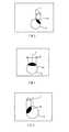
本発明の実施例1であるHMD(画像表示装置)について説明する。図1(A)は、本実施例のHMDの内部構成を側面側から見たときの概略図である。図1(B)は、上記内部構成を上面側から見たときの概略図である。 An HMD (image display apparatus) that is
本実施例のHMDでは、図1(B)に示すように、撮像素子の光軸と表示光学系の光軸とが同一面内に位置しており、観察者の瞳位置(視線軸の位置)に対する表示光学系の光軸位置(射出光軸の位置)の水平方向(図1(B)の左右方向)におけるずれを検知するものである。 In the HMD of this embodiment, as shown in FIG. 1B, the optical axis of the image sensor and the optical axis of the display optical system are located in the same plane, and the pupil position of the observer (the position of the visual axis). ) In the horizontal direction (left and right direction in FIG. 1B) of the optical axis position (position of the exit optical axis) of the display optical system with respect to ().
1はCCDセンサやCMOSセンサ等の撮像素子(撮影手段)、2は例えばLCD、LCOS、EL又はスキャン系等の画像形成素子(表示手段)、3は画像形成素子2に映像信号を送る駆動回路である。4は画像形成素子2での表示画像を拡大させる表示光学系であり、自由曲面プリズム等で構成されている。
5はHMDを装着して映像を観察する観察者の眼球である。6は撮像素子1に到達する光束の光軸、7は表示光学系4の射出光軸(実線で示す)である。図1(B)に示すように、撮像素子1の光軸6と表示光学系4の射出光軸7とが同一面内に位置するように、撮像素子1および表示光学系4が配置されている。8は観察者の視線軸である。
10はHMDでの動作を制御するコントローラ(瞳検出手段)である。11は第1の駆動ユニットであり、コントローラ10からの指令を受けて撮像素子1を図1(A)の左右方向(図1(B)の上下方向)に移動させる。12は第2の駆動ユニット(移動手段)であり、コントローラ10からの指令を受けて表示光学系4を図1(B)の左右方向(水平方向)に移動させる。
上述した構成において、画像形成素子2に形成された画像は、図1(A)に示すように、表示光学系7の第1の面4aを透過し、第2の面4bおよび第3の面4cで反射した後、第4の面4dから射出する。これにより、画像形成素子2からの光が、観察者の眼球5に導かれる。 In the configuration described above, the image formed on the
人の眼球の黒目領域はφ10mm程度が一般的である。本実施例では、図1(B)に示すように表示光学系4のアイレリーフが20mmの設計値であるとして、撮像素子1を、表示光学系4の外部であって、表示光学系4の水平方向における中心軸上に配置している。表示光学系4からの距離が20mmの位置での水平方向の撮影範囲を20mmに設定すれば、観察者がHMDを装着した際に、観察者の瞳位置が設計値に対して水平方向に±5mmだけずれていても眼球全体を撮像することができる。 The black eye area of a human eye is generally about φ10 mm. In this embodiment, as shown in FIG. 1B, assuming that the eye relief of the display
本実施例のHMDにおいて、観察者がHMDを装着して、HMDに設けられた測定開始ボタン(不図示)を操作すると、観察者の眼球5に対して照明光が照射される。そして、眼球5の反射光は撮像素子1に到達するようになっているため、撮像素子1を用いて反射像の撮像動作が行われる。 In the HMD of the present embodiment, when an observer wears the HMD and operates a measurement start button (not shown) provided on the HMD, illumination light is irradiated to the
観察者の眼球5に可視光の照明光を照射すると、観察者に不快感を与えることがあるため、本実施例では、可視領域以外の照明光である赤外光を照射している。 Irradiation of visible illumination light to the
観察者の眼球の撮像動作を行う際には、表示光学系4の射出光軸7と観察者の視線軸8が図1(B)に示すように略平行になっている必要がある。射出光軸7および視線軸8が略平行になっていなければ、後述するように表示光学系4の射出光軸7の位置(以下、光軸位置と称す)と、検出された観察者の瞳位置とが略一致するように表示光学系4を移動させても、ずれが生じてしまうからである。 When performing the imaging operation of the observer's eyeball, the exit
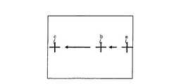
上述した測定開始ボタンを押すと、画像形成素子2には、図2に示すように表示領域内の右端aに十字の指標が映し出される。そして、指標が位置aから矢印で示す方向に細かい間隔でシフトし、例えば、位置b、cの順で指標が表示される。 When the measurement start button described above is pressed, a cross-shaped index is displayed on the right end a in the display area on the
これにより、観察者に対して指標を眼で追いかけさせるようにしている。そして、観察者が眼で指標を追いかけている間、撮像素子1において眼球像が連続的に(指標の表示位置ごとに)撮像される。なお、動画によって上記指標を表示してもよいし、指標のシフト方向は図2の矢印で示す方向とは逆の方向であってもよい。 As a result, the observer is made to follow the index with the eyes. Then, while the observer is chasing the index with the eyes, the
図3(A)から図3(C)には、指標を追っているときの眼球5の状態を示している。 FIG. 3A to FIG. 3C show the state of the
観察者の眼球5が左右方向(水平方向)のどちらか一方向に振られた状態、すなわち、観察者の視線軸8が表示光学系4の射出光軸7に対して略平行ではなく、射出光軸7に対して傾いている状態では、図3(A)に示すように眼球5の黒目領域5aのうち水平方向(射出光軸7と直交する方向)の距離(幅)がLaとなる。A state in which the observer's
一方、観察者の視線軸8が表示光学系4の射出光軸7と略平行な状態では、図3(B)に示すように眼球5の黒目領域5aのうち水平方向の距離(幅)がLbとなる。On the other hand, when the observer's
また、眼球5が他方向の振られた状態、すなわち、観察者の視線軸8が表示光学系4の射出光軸7に対して略平行ではなく、射出光軸7に対して傾いている状態では、図3(C)に示すように、眼球5の黒目領域5aのうち水平方向の距離(幅)はLcとなる。Further, the
図3(A)および図3(C)に示す状態では、視線軸8が射出光軸7に対して傾いているため、距離La、Lcは、距離Lbよりも短くなり、図3(B)に示す状態での距離Lbが最大値となる。In the state shown in FIG. 3 (A) and FIG. 3 (C), the order line of
本実施例では、撮像素子1による連続した撮像動作によって得られた複数の画像データから、眼球5が図3(B)に示す状態、すなわち、眼球5の黒目領域5aの幅が最も大きくなる状態を特定する。そして、画像形成素子2上に、図3(B)に示す状態に対応した位置にある指標を再表示させる。表示した指標を観察者に再び観察させることで、観察状態にある眼球5に対して撮像動作を行う。この状態を第1の状態とする。 In the present embodiment, the
第1の状態での撮像動作によって得られた画像データから黒目領域5aの両端を抽出して、この中心位置を瞳位置とする。ここで、瞳位置を検出する分解能は撮像素子1の分解能に依存する。例えば、瞳位置を0.1mmの間隔で検出しようとすれば、上述したように水平方向の撮像範囲を20mmに設定しているため、撮像素子1の水平方向での分解能が200(画素)以上あればよい。 Both ends of the
本実施例では、撮像素子1の水平方向の分解能が400であるとする。そして、図4に示すように撮像動作によって得られた画像の中心を原点(基準位置)とし、X座標を±200とする。また、X方向(水平方向)において、原点に対する瞳位置のずれ量をXa1とする。In this embodiment, it is assumed that the horizontal resolution of the
ここで、以下の(1)式から、ずれ量Xa1を求めることができる。Here, the shift amountXa1 can be obtained from the following equation (1).

撮像動作によって得られた眼球像は、観察者の眼球5がアイレリーフの設計値20mmに対応した位置にあるとしたときの像であるが、観察者が所望のアイレリーフの位置で表示光学系4を観察していない場合もある。この場合には、撮像した眼球像に倍率誤差(撮影倍率の誤差)が含まれていることになり、このときの瞳位置は所定のアイレリーフでの瞳位置に対してずれてしまうことがある。 The eyeball image obtained by the imaging operation is an image when the
したがって、上記ずれ(倍率誤差)を補正する必要がある。倍率誤差を補正する方法としては、撮像素子1を移動させることによって、眼球5と撮像素子1との間の距離を、撮像素子1の移動開始前の距離よりも長くする。すなわち、撮像素子1の移動開始前の光路長よりも光路長を長くすることによって撮像範囲を広げる方法がある。また、物理的に撮像素子1を移動させることができない場合には、撮像素子1を移動させたことと同じ光学作用が得られるように撮影倍率を変更してもよい。 Therefore, it is necessary to correct the deviation (magnification error). As a method of correcting the magnification error, the distance between the
以下、図5を用いて、観察状態にある瞳位置の実際のずれ量を求める動作と、該ずれ量に基づいて表示光学系4を駆動する動作について説明する。ここでは、撮像素子1を移動させる場合について説明する。 Hereinafter, an operation for obtaining an actual shift amount of the pupil position in the observation state and an operation for driving the display
ステップS1において、コントローラ10は、第1の駆動ユニット11の駆動を制御することで、撮像素子1を眼球5から遠ざかる方向に所定量(ここでは、10mm)だけ移動させる。これにより、表示光学系4から30mm離れた位置において、撮像素子1による撮影範囲が40mmになるように変更される。 In step S <b> 1, the
ステップS2において、コントローラ10は駆動回路3の駆動を制御することで、画像形成素子2に指標を第1の状態と同じ位置で表示させ、観察者に指標を観察させる。この状態を第2の状態とする。 In step S <b> 2, the
ステップS3では、第2の状態で撮像動作を行う。撮像素子1から読み出された信号はコントローラ10に出力される。ステップS4において、コントローラ10は、第2の状態での撮像動作によって得られた眼球像から、上記(1)式を用いてずれ量Xa1’を求める。In step S3, an imaging operation is performed in the second state. A signal read from the
ステップS5では、第1の状態でのずれ量Xa1と第2の状態でのずれ量Xa1’が異なっているか否かを判別する。ここで、ずれ量Xa1、Xa1’が互いに異なっている場合にはステップS6に進む。ずれ量Xa1、Xa1’が互いに異なる場合には、倍率誤差が生じていることになる。一方、ずれ量Xa1、Xa1’が異なっていなければ本フローを終了する。In step S5, it is determined whether or not the deviation amountXa1 in the first state is different from the deviation amountXa1 'in the second state. If the deviation amounts Xa1 and Xa1 ′ are different from each other, the process proceeds to step S6. When the deviation amounts Xa1 and Xa1 ′ are different from each other, a magnification error has occurred. On the other hand, if the deviation amounts Xa1 and Xa1 ′ are not different, this flow is terminated.
ここで、倍率誤差が生じている場合の眼球5および撮像素子1の位置関係について、図6を用いて説明する。なお、図6では、表示光学系4を省略している。 Here, the positional relationship between the
図6において、Aは、第1の状態における撮像素子1と眼球5との間の距離を示す。ここで、眼球5は、表示光学系4の設計値に相当する眼球位置にある。本実施例では、距離Aが、上述したアイレリーフの設計値である20mmとなっている。 In FIG. 6, A indicates the distance between the
Bは、第2の状態における撮像素子1と眼球5との間の距離を示す。ここで、眼球5は、表示光学系4の設計値に相当する眼球位置にある。本実施例では、上述したように撮像素子1を眼球5から10mmだけ遠ざかる方向に移動させているため、距離Bが30mmとなっている。 B indicates the distance between the
Cは、表示光学系4の設計値に相当する眼球位置に対する、実際に観察者が映像を観察している眼球位置のずれ量を示す。 C indicates the amount of deviation of the eyeball position where the observer actually observes the image with respect to the eyeball position corresponding to the design value of the display
以下の(2)式に、既知の値であるA、B、Xa1’、Xa1の値を代入することで、倍率誤差が補正されたずれ量、すなわち、実際の観察状態における瞳位置のずれ量Xa1”を求めることができる。これにより、正確な瞳位置を検出することができる。The following equation (2), is a known value A, B, Xa1 ', by substituting the value of Xa1, shift amounts magnification error has been corrected, i.e., the pupil position in the actual observation state The shift amount Xa1 ″ can be obtained. Thereby, an accurate pupil position can be detected.
図5のステップS6において、コントローラ10は、ずれ量Xa1”に基づいて第2の駆動ユニット12の駆動を制御することで、観察者の瞳位置が表示光学系4の光軸位置と略一致するように表示光学系4を移動させる。そして、本フローを終了する。In step S6 of FIG. 5, the
上述したように、倍率誤差が生じていると判断した場合には、瞳位置の実際のずれ量Xa1”に基づいて表示光学系4を駆動し、表示光学系4の光軸位置と瞳位置とを略一致させることで、観察者に対して画像形成素子2での表示画像をケラレることなく観察させることができる。As described above, when it is determined that a magnification error has occurred, the display
また、検出された正確な瞳位置に応じて表示光学系4を移動させるため、表示光学系4の瞳径を大きくする必要はなく、表示光学系4の大型化を抑制することができる。しかも、表示光学系4を備えたHMDの大型化を抑制できるとともに、HMDの重量が増加するのを抑制できる。 Further, since the display
一方、倍率誤差を補正するために、HMDの構成を以下に説明する構成としてもよい。すなわち、撮像素子1および表示光学系4を一体で移動できるように構成し、第1の状態にある撮像素子1および表示光学系4を水平方向に所定量移動させて、移動後の状態を第2の状態として撮像動作を行ってもよい。 On the other hand, in order to correct the magnification error, the configuration of the HMD may be described below. That is, the
ここで、図4に示す第1の状態から、例えば撮像素子1および表示光学系4を水平方向に3mmだけ移動させて第2の状態とする。そして、第2の状態での撮像動作によって得られた眼球像が図7の状態であるとする。ずれ量Xb1は、上記(1)式を用いて求めることができる。Here, from the first state shown in FIG. 4, for example, the
このとき、ずれ量Xb1、Xa1の差が、撮像素子1および表示光学系4の移動量である3mmでなければ、倍率誤差が生じていることになる。At this time, if the difference between the shift amounts Xb1 and Xa1 is not 3 mm, which is the movement amount of the
撮像素子1および表示光学系4を水平方向に移動させた場合における撮像素子1および眼球5の位置関係について、図8を用いて説明する。なお、図8では、表示光学系4を省略している。 The positional relationship between the
図8において、Aは第1の状態における撮像素子1と眼球5との間の距離を示す。ここで、眼球5は、表示光学系4の設計値に相当する眼球位置にある。本実施例では、距離Aが、上述したアイレリーフの設計値である20mmとなっている。 In FIG. 8, A indicates the distance between the
Cは、表示光学系4の設計値に相当する眼球位置に対する、実際に観察者が映像を観察している眼球位置のずれ量を示す。Dは撮像素子1の移動距離を示し、ここでは上述したように3mmとなっている。 C indicates the amount of deviation of the eyeball position where the observer actually observes the image with respect to the eyeball position corresponding to the design value of the display
以下の(3)式に、既知の値であるA、C、D、Xa1、Xb1の値を代入することで、倍率誤差が補正されたずれ量、すなわち、実際の観察状態における瞳位置のずれ量Xa1”を求めることができる。By substituting the values of A, C, D, Xa1 , and Xb1 that are known values into the following expression (3), the deviation amount in which the magnification error is corrected, that is, the pupil position in the actual observation state Displacement amount Xa1 ″ can be obtained.
そして、ずれ量Xa1”に基づいて、瞳位置が表示光学系4の光軸位置と略一致するように表示光学系4を移動させる。これにより、上述したのと同様に観察者は画像形成素子2での表示画像をケラレることなく観察することができる
なお、本実施例では、瞳位置の水平方向のずれ量を検出する場合について説明したが、本実施例と同様の検出方法を用いることで垂直方向(図1(A)の上下方向)、言い換えれば、HMDの上下方向における瞳位置のずれを検出することもできる。Then, based on the shift amount Xa1 ″, the display
次に、本発明の実施例2であるHMDについて説明する。本実施例のHMDは、観察者の視線方向を検知できるようになっている。 Next, an HMD that is
本実施例のHMDの概略構成を図9に示す。図9(A)は本実施例のHMDの内部構成を側面側から見たときの概略図である。図9(B)は上記内部構成を上面側から見たときの概略図である。これらの図において、実施例1で説明した部材と同じ部材については同一符号を付して説明を省略する。 FIG. 9 shows a schematic configuration of the HMD of this embodiment. FIG. 9A is a schematic view of the internal configuration of the HMD of this embodiment as viewed from the side. FIG. 9B is a schematic view when the internal structure is viewed from the upper surface side. In these drawings, the same members as those described in the first embodiment are denoted by the same reference numerals and description thereof is omitted.
本実施例では、図9(A)、(B)に示すように、撮像素子1の光軸6と表示光学系4の射出光軸7とが同一面内に位置し、かつ該面内において略平行となるように、表示光学系4に対して撮像素子1を配置している。 In this embodiment, as shown in FIGS. 9A and 9B, the
また、撮像素子1および表示光学系4は、駆動ユニット13によって一体的に移動する構成になっている。駆動ユニット13は、コントローラ1からの指令を受けて駆動する。 Further, the
9は記憶回路であり、駆動回路3から画像表示素子2に出力される信号(指標の位置情報)と、撮像素子1の撮像データとを対応させて記憶する。
本実施例においても、実施例1と同様に、表示光学系4のアイレリーフの設計値を20mmとし、表示光学系4からの距離が20mmの位置における水平方向の撮像範囲を20mmとする。 Also in the present embodiment, similarly to the first embodiment, the design value of the eye relief of the display
観察者が本実施例のHMDを装着した後に測定開始ボタン(不図示)を押すと、撮像素子1によって観察者の眼球像が撮像される。撮像動作を行う際には、表示光学系4の射出光軸7と観察者の視線軸8が略平行になっている必要がある。射出光軸7および視線軸8が略平行になっていなければ、後述するように表示光学系4の光軸位置を、検出した観察者の瞳位置に合わせてもずれが生じてしまうからである。 When the observer presses a measurement start button (not shown) after wearing the HMD of the present embodiment, an image of the observer's eyeball is captured by the
測定開始ボタンを押すと、図10に示すように、画像形成素子2の表示面の右端aに十字の指標が表示される。この指標は、図10の矢印で示す方向に細かい間隔でシフトし、例えば、表示位置b、cで表示される。指標が表示位置cまで移動すると、表示面の上側(図10の上側)から下側に向かって、表示位置d、b、fの順で指標が表示される。 When the measurement start button is pressed, a cross-shaped index is displayed at the right end a of the display surface of the
このように指標を表示することで、観察者に眼で指標を追いかけさせる。なお、指標は動画でもよく、表示面の右端から左端や、上端から下端に向かって連続的に指標を移動させることもできる。また、指標の表示順序や表示方向は適宜変更することができる。 Displaying the index in this way allows the observer to follow the index with the eyes. The index may be a moving image, and the index can be continuously moved from the right end to the left end of the display surface or from the upper end to the lower end. In addition, the display order and display direction of the indices can be changed as appropriate.
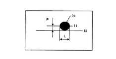
観察者が表示された指標を眼で追いかけている間、眼球像を連続的に撮像する。また、図11に示すように、連続した撮像動作によって得られた複数の眼球像のうち各眼球像の黒目領域5aのうち水平方向における幅Lと、瞳中心を通る水平線l1と画面中心線l2との間の距離(ずれ量)Pとを、指標の位置情報に対応させて記憶回路9に記憶させておく。 While the observer is chasing the displayed index with his / her eyes, an eyeball image is continuously captured. Further, as shown in FIG. 11, among the plurality of eyeball images obtained by continuous imaging operations, the horizontal width L of the
図12(A)から図12(C)には、指標を追っているときの眼球5の状態を示している。 FIGS. 12A to 12C show the state of the
観察者の眼球5が左右方向(水平方向)のどちらか一方向に振られた状態、すなわち、観察者の視線軸8が表示光学系4の射出光軸7に対して略平行ではなく、射出光軸7に対して傾いている状態では、図12(A)に示すように眼球5の黒目領域5aのうち水平方向(射出光軸7と直交する方向)の距離(幅)がLaとなる。A state in which the observer's
一方、観察者の視線軸8が表示光学系4の射出光軸7と略平行な状態では、図12(B)に示すように眼球5の黒目領域5aのうち水平方向の距離(幅)がLbとなる。On the other hand, when the observer's
また、眼球5が他方向に振られた状態、すなわち、観察者の視線軸8が表示光学系4の射出光軸7に対して略平行ではなく、射出光軸7に対して傾いている状態では、図12(C)に示すように、眼球5の黒目領域5aのうち水平方向の距離(幅)はLcとなる。Further, the
図12(A)および図12(C)に示す状態では、視線軸8が射出光軸7に対して傾いているため、距離La、Lcは、距離Lbよりも短くなり、図12(B)に示す状態での距離Lbが最大値となる。In the state shown in FIG. 12 (A) and FIG. 12 (C), the order line of
本実施例では、撮像素子1の連続した撮像動作によって得られた複数の画像データから、眼球5が図12(B)に示す状態、すなわち、眼球5の黒目領域5aの幅が最も大きくなる状態を特定する。そして、画像形成素子2上に、図12(B)に示す状態に対応した位置にある指標を再表示させる。表示した指標を観察者に再び観察させることで、観察状態にある眼球5に対して撮像動作を行う。この状態を第1の状態とする。 In this embodiment, the
第1の状態での撮像動作によって得られた画像データから黒目領域5aの両端を抽出して、この中心位置を瞳位置とする。 Both ends of the
また、垂直方向に関して、黒目領域5aの上下の領域は瞼で隠れることが多く、撮像動作によって得られた黒目領域5aの曲線の曲率半径から瞼で隠れている領域を補完し、上述した水平方向と同様の検出方法を行う。 Further, with respect to the vertical direction, the upper and lower regions of the
垂直方向でのずれ量は水平方向の場合に比べて、HMDを装着する観察者に応じて個人差が大きくなる。本実施例では、HMDが観察者の見やすい位置の近傍に装着されているとして、微妙なずれを補正するために、図11に示すずれ量Pに基づいて垂直方向における瞳位置のずれを検出する。 The amount of deviation in the vertical direction varies depending on the observer wearing the HMD, as compared to the horizontal direction. In this embodiment, assuming that the HMD is mounted in the vicinity of a position that is easy for the observer to see, in order to correct a slight shift, a pupil position shift in the vertical direction is detected based on the shift amount P shown in FIG. .
本実施例では、撮像素子1の水平方向の分解能が400であるとする。そして、図11に示すように撮像動作によって得られた画像の中心を原点とし、X座標を±200とし、Y座標を±200とする。 In this embodiment, it is assumed that the horizontal resolution of the
ここで、実施例1に示す(1)式を用いることで、図13に示すようにX方向(水平方向)におけるずれ量Xa2と、Y方向(垂直方向)におけるずれ量Ya2を求めることができる。ずれ量Xa2は、画像の中心(X=0)に対する瞳位置のX方向におけるずれ量であり、ずれ量Ya2は、画像中心(Y=0)に対する瞳位置のY方向におけるずれ量である。Here, by using the equation (1) shown in Example 1, obtaining a shift amount Xa2 in the X direction (horizontal direction) as shown in FIG. 13, the shift amount Ya2 in the Y direction (vertical direction) Can do. The shift amountXa2 is the shift amount in the X direction of the pupil position with respect to the center (X = 0) of the image, and the shift amountYa2 is the shift amount in the Y direction of the pupil position with respect to the image center (Y = 0). .
撮像動作によって得られた眼球像は、観察者の眼球5がアイレリーフの設計値20mmに対応した位置にあるとしたときの像であるが、観察者が所望のアイレリーフの位置で表示光学系4を観察していない場合もある。この場合には、撮像した眼球像に倍率誤差が含まれていることになり、このときの瞳位置は所定のアイレリーフでの瞳位置に対してずれてしまうことがある。 The eyeball image obtained by the imaging operation is an image when the
したがって、上記ずれ(倍率誤差)を補正する必要がある。倍率誤差を補正する方法としては、実施例1で説明した方法がある。 Therefore, it is necessary to correct the deviation (magnification error). As a method of correcting the magnification error, there is the method described in the first embodiment.
本実施例では、撮像素子1を例えば10mmだけ眼球5から遠ざかる方向に移動させて、表示光学系4から30mm離れた位置における撮像範囲が40mmになるように変更する。そして、画像形成素子2に指標を第1の状態と同じ位置で表示させ、観察者に指標を観察させる。この状態を第2の状態とする。 In this embodiment, the
そして、第2の状態で撮像動作を行う。第2の状態での撮像動作によって得られた眼球像から、実施例1に示す(1)式を用いてずれ量Xa2’を求める。ここで、第1の状態でのずれ量Xa2と第2の状態でのずれ量Xa2’が互いに異なる場合には、倍率誤差が生じていることになる。Then, the imaging operation is performed in the second state. The deviation amount Xa2 ′ is obtained from the eyeball image obtained by the imaging operation in the second state using the equation (1) shown in the first embodiment. Here, when the deviation amount Xa2 in the first state and the deviation amount Xa2 ′ in the second state are different from each other, a magnification error has occurred.
このようにずれ量が異なる場合には、実施例1に示す(2)式を用いることで、倍率誤差を補正したずれ量、すなわち、実際の観察状態における瞳位置のずれ量Xa2”を求める。When the deviation amounts are different as described above, the deviation amount in which the magnification error is corrected, that is, the pupil position deviation amount Xa2 ″ in the actual observation state is obtained by using the expression (2) shown in the first embodiment. .
一方、X方向に関して倍率誤差が生じている場合には、Y方向に関しても倍率誤差が生じているため、X方向でのずれ量を求めた場合と同様にして、(1)式および(2)式を用いることで、Y方向に関して倍率誤差を補正したずれ量、すなわち、実際の観察状態における瞳位置のY方向でのずれ量Ya2”を求める。On the other hand, when a magnification error has occurred in the X direction, since a magnification error has also occurred in the Y direction, equations (1) and (2) are obtained in the same manner as when the amount of deviation in the X direction is obtained. By using the equation, a deviation amount in which the magnification error is corrected in the Y direction, that is, a deviation amount Ya2 ″ in the Y direction of the pupil position in the actual observation state is obtained.
そして、コントローラ10は、求められたずれ量Xa2”、Ya2”に基づいて駆動ユニット13の駆動を制御することで、観察者の瞳位置が表示光学系4の光軸位置と略一致するように、表示光学系4(撮像素子1を含む)をX方向およびY方向に移動させる。これにより、画像形成素子2での表示画像を観察者にケラレることなく観察させることが可能になる。また、表示光学系4を移動させるため、瞳径を大きくするために表示光学系4全体を大型化させる必要はなくなる。Then, the
また、本実施例では、観察者の瞳位置を検出する際に観察者が指標を注視して追いかけている眼球像と指標の位置情報を対応付けて記憶回路9に記憶させている。 Further, in this embodiment, when detecting the observer's pupil position, the eyeball image that the observer is chasing after following the index and the position information of the index are stored in the
このデータは表示光学系4が初期状態(第1の状態)にあるときのデータであるため、瞳位置および表示光学系の光軸位置を略一致させるために表示光学系4をX方向およびY方向に移動させた量に基づいて、上記データを補正する。 Since this data is data when the display
そして、瞳位置および表示光学系4の光軸位置を略一致させた後も、連続的に観察者の眼球像を撮像して、図11に示すように黒目領域5aの幅Lとずれ量Pを検出する。コントローラ(視線検出手段)10は、検出したデータと、上記補正後のデータとを照らし合わせることで、画像形成素子2の表示領域のうち観察者がどの位置を注視しているかを検出することができる。 Then, even after the pupil position and the optical axis position of the display
そして、観察者がHMDを装着するたびに眼球像の撮像を行うことで、記憶回路9内のデータを書き換える。これにより、眼球の大きさなどの個人差による影響を受けることなく注視点又は視線方向を検出することが可能である。 Then, every time the observer wears the HMD, the eyeball image is taken to rewrite the data in the
そして、検出した注視点又は視線方向軸が表示光学系4の光軸と略一致するように表示光学系4を移動させる。これにより、画像表示素子2での表示画像がケラレることなく観察者に観察させることができる。 Then, the display
次に、本発明の実施例3であるHMDについて説明する。本実施例のHMDでは、観察者の両眼それぞれに対応させて画像表示素子や表示光学系等が設けられており、観察者の眼幅を検出できるようになっている。 Next, an HMD that is
図14(A)は、本実施例のHMDの内部構成を側面側から見たときの概略図である。図14(B)は、上記内部構成を上面側から見たときの概略図である。これらの図において、実施例1、2で説明した部材と同じ部材については同一符号を用い、詳細な説明は省略する。 FIG. 14A is a schematic diagram when the internal configuration of the HMD of this embodiment is viewed from the side surface side. FIG. 14B is a schematic view when the internal structure is viewed from the upper surface side. In these drawings, the same members as those described in the first and second embodiments are denoted by the same reference numerals, and detailed description thereof is omitted.
ここで、撮像素子1は表示光学系4に対して、撮像素子1の光軸6と表示光学系4の射出光軸7とが同一面内に位置するように配置されている。なお、上記構成に加えて、実施例2と同様に、光軸6と射出光軸7とが上記面内において略平行となるように、撮像素子1および表示光学系4を配置してもよい。 Here, the
本実施例では、左右の眼に対応した各画像形成素子2の駆動を1つの駆動回路3で行っているが、画像形成素子毎に駆動回路を設けてもよい。 In this embodiment, each
人の眼幅は55mmから75mm程度の幅であり、一般的には65mm程度が最も多いと言われている。また、眼球の黒目領域はφ10mm程度が一般的である。 The human eye width is about 55 mm to 75 mm, and generally about 65 mm is said to be the most common. Also, the black eye region of the eyeball is generally about φ10 mm.
従って、例えば左右の眼幅を65mmとしておき、表示光学系4のアイレリーフの設計値を20mmとし、各撮像素子1を各表示光学系4の水平方向における中心軸上に配置する場合、表示光学系4からの距離が20mmの位置における水平方向の撮像範囲を30mmに設定すれば、HMDを装着した観察者の瞳位置が設計値に対して水平方向に±10mmだけずれていても眼球全体を撮像することができる。 Therefore, for example, when the left and right eye widths are set to 65 mm, the eye relief design value of the display
観察者が本実施例のHMDを装着して、HMDに設けられた測定開始ボタン(不図示)を操作すると、観察者の眼球5に照明光が照射され、反射光が撮像素子1に到達することで、撮像素子1において撮像動作が行われる。 When an observer wears the HMD of this embodiment and operates a measurement start button (not shown) provided on the HMD, illumination light is irradiated on the
ここで、観察者の眼球5に可視光の照明光を照射すると、観察者に不快感を与えることがあるため、本実施例では、可視領域以外の照明光である赤外光を照射している。 Here, irradiating the observer's
瞳位置を検出する場合において、無限遠を観察した状態の瞳位置でなければ左右の眼球に輻輳がついており、左右の瞳位置の間隔から算出する観察者の眼幅も誤差を含んだ値になる。また、後述するように、検出した観察者の瞳位置に表示光学系4の光軸位置を合わせても、表示光学系4の射出光軸7および観察者の視線軸8がずれている可能性がある。 When detecting the pupil position, the left and right eyeballs are congested if the pupil position is not observed at infinity, and the eye width of the observer calculated from the interval between the left and right pupil positions also includes an error. Become. Further, as will be described later, even if the optical axis position of the display
本実施例のHMDにおいて、観察者が測定開始ボタンを押すと、左眼用および右眼用の画像形成素子2には、図15に示すように、十字の指標が表示領域内の右端aに表示される。この指標は、図15の矢印で示す方向に向かって細かな間隔でシフトし、表示位置b、cの順に表示される。これにより、観察者に指標を眼で追いかけさせるようにしている。 In the HMD of this embodiment, when the observer presses the measurement start button, a cross-shaped index is displayed at the right end a in the display area in the left-eye and right-eye
なお、動画表示によって指標を連続的に移動させることもできるし、指標のシフト方向を適宜設定することもできる。 The index can be continuously moved by moving image display, and the shift direction of the index can be set as appropriate.
本実施例では、指標を移動させている間に、眼球像を連続的に撮像する。 In the present embodiment, the eyeball image is continuously captured while the index is moved.
図16(A)から図16(C)には、指標を追っているときの右眼の眼球5の状態を示している。 FIGS. 16A to 16C show the state of the right-
観察者の眼球5が無限遠方向ではなく左右方向のどちらか一方向に振られた状態、すなわち、観察者の視線軸8が表示光学系4の射出光軸7に対して略平行ではなく、射出光軸7に対して傾いている状態では、図16(A)に示すように眼球5の黒目領域5aのうち水平方向(射出光軸7と直交する方向)の距離(幅)がLaとなる。The state in which the observer's
一方、観察者が無限遠方向を観察しており、観察者の視線軸8が表示光学系4の射出光軸7と略平行な状態では、図16(B)に示すように眼球5の黒目領域5aのうち水平方向の距離(幅)がLbとなる。On the other hand, when the observer observes the infinity direction and the observer's line of
また、眼球5が他方向に振られた状態、すなわち、観察者の視線軸8が表示光学系4の射出光軸7に対して略平行ではなく、射出光軸7に対して傾いている状態では、図16(C)に示すように、眼球5の黒目領域5aのうち水平方向の距離(幅)はLcとなる。Further, the
図16(A)、(C)に示す状態では、視線軸8が射出光軸7に対して傾いているため、距離La、Lcは、距離Lbよりも短くなり、図16(B)に示す状態での距離Lbが最大値となる。FIG. 16 (A), the in state (C), the order line of
本実施例では、撮像素子1の連続した撮像動作によって得られた複数の画像データから、眼球5が図16(B)に示す状態、すなわち、眼球5の黒目領域5aの幅が最も大きくなる状態を特定する。そして、画像形成素子2上に、図16(B)に示す状態(無限遠での観察状態)に対応した位置にある指標を再表示させる。表示した指標を観察者に再び観察させることで、観察状態にある眼球5に対して撮像動作を行う。この状態を第1の状態とする。 In this embodiment, the
第1の状態での撮像動作によって得られた画像データ(眼球像)から黒目領域5aの両端を抽出して、この中心位置を瞳位置とする。 Both ends of the
ここで、瞳位置を検出する分解能は撮像素子1の分解能に依存する。例えば、瞳位置を0.1mmの間隔で検出しようとすれば、上述したように水平方向の撮像範囲を30mmに設定しているため、撮像素子1の水平方向での分解能が300(画素)以上あればよい。 Here, the resolution for detecting the pupil position depends on the resolution of the
本実施例では、撮像素子1の水平方向の分解能が600であるとする。そして、図17に示すように撮像動作によって得られた画像の中心を原点とし、X座標を±300とする。また、X方向(水平方向)において、原点に対する右眼の瞳位置のずれ量をXc1とする。また、X方向において、原点に対する左眼の瞳位置のずれ量をXd1とする。In this embodiment, it is assumed that the horizontal resolution of the
ずれ量Xc1、Xd1は、実施例1に示す(1)式を用いて求めることができる。The deviation amounts Xc1 and Xd1 can be obtained using the equation (1) shown in the first embodiment.
撮像動作によって得られた眼球像は、観察者の眼球5がアイレリーフの設計値20mmに対応した位置にあるとしたときの像であるが、観察者が所望のアイレリーフの位置で表示光学系4を観察していない場合もある。この場合には、撮像した眼球像に倍率誤差が含まれていることになり、このときの瞳位置は所定のアイレリーフでの瞳位置に対してずれてしまうことがある。 The eyeball image obtained by the imaging operation is an image when the
したがって、上記ずれ(倍率誤差)を補正する必要がある。倍率誤差を補正する方法としては、撮像素子1を移動させることによって、眼球5と撮像素子1との間の距離を、撮像素子1の移動開始前の距離よりも長くする。すなわち、撮像素子1の移動開始前の光路長よりも光路長を長くすることによって撮像範囲を広げる方法がある。また、物理的に撮像素子1を移動させることができない場合には、撮像素子1を移動させたことと同じ光学作用が得られるように撮影倍率を変更してもよい。 Therefore, it is necessary to correct the deviation (magnification error). As a method of correcting the magnification error, the distance between the
本実施例では、撮像素子1を例えば10mmだけ眼球5から遠ざかる方向に移動させて、表示光学系4から30mm離れた位置における撮像範囲が40mmになるように変更する。そして、画像形成素子2に指標を第1の状態と同じ位置で表示させ、観察者に指標を観察させる。この状態を第2の状態とする。 In this embodiment, the
そして、第2の状態で撮像動作を行う。第2の状態での撮像動作によって得られた右眼および左眼の眼球像から、実施例1に示す(1)式を用いてずれ量Xc1’、Xd1’を求める。ここで、第1の状態でのずれ量Xc1、Xd1と第2の状態でのずれ量Xc1’、Xd1’が互いに異なる場合には、倍率誤差が生じていることになる。Then, the imaging operation is performed in the second state. Deviation amounts Xc1 ′ and Xd1 ′ are obtained from the right eye and left eye eyeball images obtained by the imaging operation in the second state using the equation (1) shown in the first embodiment. Here, if the shift amounts Xc1 and Xd1 in the first state and the shift amounts Xc1 ′ and Xd1 ′ in the second state are different from each other, a magnification error has occurred.
このように倍率誤差が生じている場合には、実施例1に示す(2)式を用いることで、実際の観察状態でのずれ量Xc1”、Xd1”、すなわち、倍率誤差を補正したずれ量を求める。When a magnification error occurs in this way, the deviations Xc1 ″, Xd1 ″ in the actual observation state, that is, the magnification error is corrected by using the expression (2) shown in Example 1. Find the amount of deviation.
一方、倍率誤差を補正するために、以下に説明する構成としてもよい。すなわち、実施例2と同様に、撮像素子1および表示光学系4を一体で移動できるように構成し、第1の状態にある撮像素子1および表示光学系4を水平方向に所定量移動させて、移動後の状態を第2の状態として撮像動作を行ってもよい。 On the other hand, in order to correct the magnification error, a configuration described below may be adopted. That is, as in the second embodiment, the
例えば、図17に示す状態にある左眼用および右眼用の表示光学系4それぞれを、該中心位置から外側に1.5mmずつ移動させて、眼幅を68mmに変更した後に撮像した眼球像が図18の状態であるとする。このとき、実施例1に示す(1)式を用いて算出したずれ量Xe1およびずれ量Xc1の差が1.5mmでなかったり、ずれ量Xf1およびずれ量Xd1の差が1.5mmでなかったりした場合には、倍率誤差が生じていることになる。For example, each of the left-eye and right-eye display
このように倍率誤差が生じている場合には、コントローラ(眼幅検出手段)10は、実施例1に示す(3)式を用いることで、倍率誤差が補正されたずれ量、すなわち、実際の観察状態での瞳位置のずれ量を求めることができる。これにより、正確な瞳位置(眼幅)を検出することができる。 When a magnification error has occurred in this way, the controller (eye width detection means) 10 uses the expression (3) shown in the first embodiment, so that the deviation amount in which the magnification error is corrected, that is, the actual amount is corrected. The amount of pupil position shift in the observation state can be obtained. Thereby, an exact pupil position (eye width) can be detected.
第1の状態では、左眼用および右眼用の表示光学系4の間隔を65mmとして測定を行っているため、ずれ量Xc1”、Xd1”から観察者の眼幅を算出することができる。また、表示光学系4を移動させた後の第2の状態では、表示光学系4の間隔が68mmであるため、実施例1に示す(3)式を用いてずれ量Xe1”、Xf1”を算出することで眼幅を求めることもできる。In the first state, since the measurement is performed with the interval between the display
倍率誤差を補正することによって、左眼および右眼のそれぞれにおいて、観察者の瞳位置に対する表示光学系4の射出光軸7の正確なずれ量を検出することができる。そして、検出したずれ量に基づいて、各瞳位置と各表示光学系4の光軸位置とが略一致するように、各表示光学系4(又は表示光学系および撮像素子)を移動させることで、観察者は画像形成素子2での表示画像をケラレることなく観察することができる。 By correcting the magnification error, it is possible to detect an accurate shift amount of the emission
次に、本発明の実施例4であるHMDについて説明する。本実施例のHMDは、観察者の両眼それぞれに対応させて画像表示素子や表示光学系が設けられており、観察者の注視点方向(視線方向)を検知できるものである。 Next, an HMD that is
図19(A)は、本実施例のHMDの内部構成を側面側から見たときの概略図である。図19(B)は、上記内部構成を上面側から見たときの概略図である。これらの図において、実施例1や実施例2で説明した部材と同じ部材については同一符号を用い、詳細な説明は省略する。 FIG. 19A is a schematic diagram when the internal configuration of the HMD of this embodiment is viewed from the side surface side. FIG. 19B is a schematic view when the internal structure is viewed from the upper surface side. In these drawings, the same members as those described in the first and second embodiments are denoted by the same reference numerals, and detailed description thereof is omitted.
撮像素子1は表示光学系4に対して、撮像素子1の光軸6と表示光学系4の射出光軸7とが同一面内に位置し、かつ該面内において略平行となるように、配置されている。また、撮像素子1および表示光学系4は、駆動ユニット13によって一体となって移動可能となっている。 The
本実施例において、記憶回路9には、駆動回路3から画像表示素子2に出力される信号(指標の位置情報)と、撮像素子1の撮像データとが対応して記憶されている。 In the present embodiment, the
ここで、左右の眼幅を65mmとしておき、表示光学系3のアイレリーフの設計値を20mmとし、各撮像素子1を各表示光学系4の左右方向における中心軸上に配置する場合には、表示光学系3からの距離が20mmの位置における水平方向の撮像範囲を30mmに設定しておく。 Here, when the left and right eye width is set to 65 mm, the design value of the eye relief of the display
本実施例では、左眼および右眼に対応した各画像形成素子2を1つの駆動回路3で駆動している。また、1つの記憶回路9が設けられている。なお、画像形成素子毎に駆動回路3や記憶回路9を設けてもよい。 In this embodiment, each
瞳位置を検出する場合、無限遠を観察した状態の瞳位置でなければ左右の眼球に輻輳がついており、左右の瞳位置の間隔から算出する観察者の眼幅も誤差を含んだ値になる。また、後述するように、検出した観察者の瞳位置に表示光学系4の光軸位置を合わせても表示光学系4の射出光軸7と観察者の視線軸8がずれてしまう可能性がある。 When detecting the pupil position, the left and right eyeballs are congested if the pupil position is not observed at infinity, and the eye width of the observer calculated from the interval between the left and right pupil positions also includes an error. . Further, as will be described later, even if the optical axis position of the display
観察者が本実施例のHMDを装着した後に、HMDに設けられた測定開始ボタン(不図示)を操作すると、左眼用および右眼用の各画像形成素子2には、図20に示すように表示画面の右端aに十字の指標が表示される。この指標は、矢印で示す方向に細かい間隔でシフトし、表示位置b、cの順に表示される。また、表示位置cまで指標が移動した後は、表示位置dで指標が表示され、表示位置d、b、fの順に表示される。 When the observer operates the measurement start button (not shown) provided on the HMD after wearing the HMD of this embodiment, the left-eye and right-eye
このように指標の位置をシフトさせることで、観察者に指標を眼で追いかけさせる。なお、動画表示によって指標を連続的に移動させることもできるし、指標の移動方向を適宜設定することもできる。 By shifting the position of the index in this way, the observer is chased by the eye with the index. The index can be continuously moved by moving image display, and the moving direction of the index can be set as appropriate.
観察者が表示された指標を眼で追いかけている間、眼球像を連続的に撮像する。また、連続した撮像動作によって得られた複数の眼球像のうち各眼球像の黒目領域のうち水平方向における幅Lと、瞳中心を通る水平線l1と画面中心線l2との間の距離(ずれ量)Pと(図21参照)を、指標の位置情報に対応させて記憶回路9に記憶させておく。 While the observer is chasing the displayed index with his / her eyes, an eyeball image is continuously captured. Also, among the plurality of eyeball images obtained by continuous imaging operations, the horizontal width L of the black eye region of each eyeball image, and the distance (deviation amount) between the
図22(A)から図22(C)には、指標を追っているときの右眼の眼球5の状態を示している。 22A to 22C show the state of the right-
観察者の眼球5が無限遠方向ではなく左右方向のどちらか一方向に振られた状態、すなわち、観察者の視線軸8が表示光学系4の射出光軸7に対して略平行ではなく、射出光軸7に対して傾いている状態では、図22(A)に示すように眼球5の黒目領域のうち水平方向(射出光軸7と直交する方向)の距離(幅)がLaとなる。The state in which the observer's
一方、観察者が無限遠方向を観察しており、観察者の視線軸8が表示光学系4の射出光軸7と略平行な状態では、図22(B)に示すように眼球5の黒目領域のうち水平方向の距離(幅)がLbとなる。On the other hand, when the observer observes the infinity direction and the observer's line-of-
また、眼球5が他方向に振られた状態、すなわち、観察者の視線軸8が表示光学系4の射出光軸7に対して略平行ではなく、射出光軸7に対して傾いている状態では、図22(C)に示すように、眼球5の黒目領域のうち水平方向の距離(幅)はLcとなる。Further, the
図22(A)および図22(C)に示す状態では、視線軸8が射出光軸7に対して傾いているため、距離La、Lcは、距離Lbよりも短くなり、図22(B)に示す状態での距離Lbが最大値となる。In the state shown in FIG. 22 (A) and FIG. 22 (C), since the line of
本実施例では、撮像素子1の連続した撮像動作によって得られた複数の画像データから、眼球5が図22(B)に示す状態、すなわち、眼球5の黒目領域の幅が最も大きくなる状態を特定する。そして、画像形成素子2上に、図22(B)に示す状態(無限遠での観察状態)に対応した位置にある指標を再表示させる。表示した指標を観察者に再び観察させることで、観察状態にある眼球5に対して撮像動作を行う。この状態を第1の状態とする。 In the present embodiment, the state in which the
第1の状態での撮像動作によって得られた画像データから黒目領域の両端を抽出して、この中心位置を瞳位置とする。 Both ends of the black eye region are extracted from the image data obtained by the imaging operation in the first state, and this center position is set as the pupil position.
また、垂直方向に関して、黒目領域の上下の領域は瞼で隠れることが多く、撮像動作によって得られた黒目領域の曲線の曲率半径から瞼で隠れている領域を補完し、上述した水平方向と同様の検出方法を行う。 Also, with respect to the vertical direction, the upper and lower areas of the black eye area are often hidden by the eyelids, complementing the area hidden by the eyelids from the curvature radius of the curve of the black eye area obtained by the imaging operation, and similar to the horizontal direction described above The detection method is performed.
垂直方向でのずれ量は水平方向の場合に比べて、HMDを装着する観察者に応じて個人差が大きくなる。本実施例では、HMDが観察者の見やすい位置の近傍に装着されているとして、微妙なずれを補正するために、図21に示すずれ量Pに基づいて垂直方向における瞳位置のずれを検出する。 The amount of deviation in the vertical direction varies depending on the observer wearing the HMD, as compared to the horizontal direction. In this embodiment, assuming that the HMD is mounted in the vicinity of a position that is easy for the observer to see, in order to correct a slight shift, a pupil position shift in the vertical direction is detected based on the shift amount P shown in FIG. .
ここで、瞳位置を検出する分解能は撮像素子1の分解能に依存する。例えば、瞳位置を0.1mmの間隔で検出しようとすれば、上述したように水平方向の撮像範囲を30mmに設定しているため、撮像素子1の水平方向での分解能が300(画素)以上あればよい。また、垂直方向に関しても同様である。 Here, the resolution for detecting the pupil position depends on the resolution of the
本実施例では、撮像素子1の水平方向の分解能が600であるとする。そして、図23に示すように撮像動作によって得られた画像の中心を原点とし、X座標を±300とし、Y座標を±200とする。 In this embodiment, it is assumed that the horizontal resolution of the
ここで、実施例1に示す(1)式を用いることで、図23に示すように、右眼におけるX方向(水平方向)のずれ量Xc2およびY方向(垂直方向)のずれ量Yc2を求めることができる。ずれ量Xc2は、画像の中心(X=0)に対する右眼の瞳位置のX方向におけるずれ量であり、ずれ量Yc2は、画像中心(Y=0)に対する右眼の瞳位置のY方向におけるずれ量である。Here, by using the expression (1) shown in the first embodiment, as shown in FIG. 23, the deviation amount Xc2 in the X direction (horizontal direction) and the deviation amount Yc2 in the Y direction (vertical direction) in the right eye. Can be requested. The shift amountXc2 is the shift amount in the X direction of the pupil position of the right eye with respect to the center (X = 0) of the image, and the shift amountYc2 is Y of the pupil position of the right eye with respect to the image center (Y = 0). The amount of deviation in the direction.
同様に、実施例1に示す(1)式を用いることで、図23に示すように、右眼におけるX方向(水平方向)のずれ量Xd2およびY方向(垂直方向)のずれ量Yd2を求めることができる。ずれ量Xd2は、画像の中心(X=0)に対する右眼の瞳位置のX方向におけるずれ量であり、ずれ量Yd2は、画像中心(Y=0)に対する右眼の瞳位置のY方向におけるずれ量である。Similarly, by using the expression (1) shown in the first embodiment, as shown in FIG. 23, the deviation amount Xd2 in the X direction (horizontal direction) and the deviation amount Yd2 in the Y direction (vertical direction) in the right eye. Can be requested. The shift amount Xd2 is a shift amount in the X direction of the right eye pupil position with respect to the center (X = 0) of the image, and the shift amount Yd2 is Y of the right eye pupil position with respect to the image center (Y = 0). The amount of deviation in the direction.
撮像動作によって得られた眼球像は、観察者の眼球5がアイレリーフの設計値20mmに対応した位置にあるとしたときの像であるが、観察者が所望のアイレリーフの位置で表示光学系4を観察していない場合もある。この場合には、撮像した眼球像に倍率誤差が含まれていることになり、このときの瞳位置は所定のアイレリーフでの瞳位置に対してずれてしまうことがある。 The eyeball image obtained by the imaging operation is an image when the
したがって、上記ずれ(倍率誤差)を補正する必要がある。倍率誤差を補正する方法としては、撮像素子1を移動させることによって、眼球5と撮像素子1との間の距離を、撮像素子1の移動開始前の距離よりも長くする。すなわち、撮像素子1の移動開始前の光路長よりも光路長を長くすることによって撮像範囲を広げる方法がある。また、物理的に撮像素子1を移動させることができない場合には、撮像素子1を移動させたことと同じ光学作用が得られるように撮影倍率を変更してもよい。 Therefore, it is necessary to correct the deviation (magnification error). As a method of correcting the magnification error, the distance between the
本実施例では、撮像素子1を例えば10mmだけ眼球5から遠ざかる方向に移動させて、表示光学系4から30mm離れた位置における撮像範囲が40mmになるように変更する。そして、画像形成素子2に指標を第1の状態と同じ位置で表示させ、観察者に指標を観察させる。この状態を第2の状態とする。 In this embodiment, the
そして、第2の状態で撮像動作を行う。第2の状態での撮像動作によって得られた右眼および左眼の眼球像から、実施例1に示す(1)式を用いてずれ量Xc2’、Xd2’を求める。ここで、第1の状態でのずれ量Xc2、Xd2と第2の状態でのずれ量Xc2’、Xd2’が互いに異なる場合には、倍率誤差が生じていることになる。Then, the imaging operation is performed in the second state. Deviation amounts Xc2 ′ and Xd2 ′ are obtained from the right-eye and left-eye eyeball images obtained by the imaging operation in the second state using equation (1) shown in the first embodiment. Here, when the shift amounts Xc2 and Xd2 in the first state and the shift amounts Xc2 ′ and Xd2 ′ in the second state are different from each other, a magnification error has occurred.
このように倍率誤差が生じている場合には、実施例1に示す(2)式を用いることで、実際の観察状態でのずれ量Xc2”、Xd2”、すなわち、倍率誤差を補正したずれ量を求める。第1の状態では、左眼用および右眼用の表示光学系4の間隔を65mmとして測定を行っているため、ずれ量Xc2”、Xd2”から観察者の眼幅を算出することができる。When a magnification error has occurred as described above, the deviation amounts Xc2 ″, Xd2 ″ in the actual observation state, that is, the magnification error is corrected by using the expression (2) shown in Example 1. Find the amount of deviation. In the first state, the distance between the left-eye and right-eye display
一方、X方向に関して倍率誤差が生じている場合には、Y方向に関しても倍率誤差が生じているため、X方向でのずれ量を求めた場合と同様にして、(1)式および(2)式を用いることで、Y方向に関して倍率誤差を補正したずれ量、すなわち、実際の観察状態における瞳位置のY方向でのずれ量Yc2”、Yd2”を求める。On the other hand, when a magnification error has occurred in the X direction, since a magnification error has also occurred in the Y direction, equations (1) and (2) are obtained in the same manner as when the amount of deviation in the X direction is obtained. By using the equation, a deviation amount obtained by correcting the magnification error in the Y direction, that is, a deviation amount Yc2 ″, Yd2 ″ in the Y direction of the pupil position in the actual observation state is obtained.
倍率誤差を補正することによって、左眼および右眼のそれぞれにおいて、観察者の瞳位置に対する表示光学系4の射出光軸7の正確なずれ量を検出することができる。そして、検出したずれ量Xc2”、Yc2”やずれ量Xd2”、Yd2”に基づいて、各瞳位置と各表示光学系4の光軸位置とが略一致するように、各表示光学系4(又は表示光学系および撮像素子)をX方向およびY方向に移動させることで、観察者は画像形成素子2での表示画像をケラレることなく観察することができる。By correcting the magnification error, it is possible to detect an accurate shift amount of the emission
また、本実施例では、観察者の瞳位置を検出する際に観察者が指標を注視して追いかけている眼球像と指標の位置情報を対応付けて記憶回路9に記憶させている。 Further, in this embodiment, when detecting the observer's pupil position, the eyeball image that the observer is chasing after following the index and the position information of the index are stored in the
このデータは表示光学系4が初期状態(第1の状態)にあるときのデータであるため、瞳位置および表示光学系の光軸位置を略一致させるために表示光学系4をX方向およびY方向に移動させた量に基づいて、上記データを補正する。 Since this data is data when the display
そして、瞳位置および表示光学系4の光軸位置を略一致させた後も、連続的に観察者の眼球像を撮像して、図21に示すように黒目領域5aの幅Lとずれ量Pを検出する。この検出したデータと、上記補正後のデータとを照らし合わせることで、画像形成素子2の表示領域のうち観察者の左眼および右眼がどの位置を注視しているかを検出することができる。これにより、観察者の注視点を検出することができる。 Then, even after the pupil position and the optical axis position of the display
そして、観察者がHMDを装着するたびに眼球像の撮像を行うことで、記憶回路9内のデータを書き換える。これにより、眼球の大きさなどの個人差による影響を受けることなく注視点又は視線方向を検出することが可能である。 Then, every time the observer wears the HMD, the eyeball image is taken to rewrite the data in the
そして、検出した注視点又は視線方向軸が表示光学系4の光軸と略一致するように表示光学系4を移動させる。これにより、画像表示素子2での表示画像がケラレることなく観察者に観察させることができる。 Then, the display
なお、本発明は、HMDを用いたMR(Mixed Reality)技術に適用することができる。すなわち、現実空間をミラー部材を介して直接見て仮想空間と重ねる機能、又は現実空間をビデオカメラで撮影して仮想空間と合成して表示する機能を備えたHMDに適用することができる。 The present invention can be applied to MR (Mixed Reality) technology using HMD. That is, the present invention can be applied to an HMD having a function of directly viewing a real space through a mirror member and superimposing it on the virtual space, or a function of photographing the real space with a video camera and combining it with the virtual space.
1 撮像素子(撮影手段)
2 画像形成素子
3 駆動回路
4 表示光学系
5 観察者の眼球
6 撮像素子の光軸
7 表示光学系の光軸
8 観察者の視線軸
9 記憶回路
1 Image sensor (photographing means)
2 Image forming
Claims (11)
Translated fromJapanese該撮影手段により得られた撮影画像に基づいて前記眼内の瞳位置を検出する瞳検出手段とを有し、
前記瞳検出手段は、複数の状態で前記撮影手段により得られた撮影画像に基づいて前記瞳位置を求めることを特徴とする眼検出装置。Photographing means for photographing an eye image;
Pupil detection means for detecting a pupil position in the eye based on a photographed image obtained by the photographing means;
The eye detection device, wherein the pupil detection unit obtains the pupil position based on captured images obtained by the imaging unit in a plurality of states.
該瞳位置に基づいて前記左右の眼の間隔を求める眼幅検出手段をさらに有することを特徴とする請求項1から7のいずれか1つに記載の眼検出装置。The pupil detection means obtains the pupil position in each of the left and right eyes;
The eye detection device according to any one of claims 1 to 7, further comprising eye width detection means for obtaining an interval between the left and right eyes based on the pupil position.
画像を形成する画像形成素子と、
該画像形成素子からの光を観察者の眼に導く光学系と、
前記眼検出装置からの情報に基づいて前記光学系を前記眼に対して移動させる移動手段とを有することを特徴とする画像表示装置。The eye detection device according to any one of claims 1 to 8,
An image forming element for forming an image;
An optical system for guiding light from the image forming element to the eyes of an observer;
An image display device comprising: moving means for moving the optical system with respect to the eye based on information from the eye detection device.
The moving means obtains a difference in a direction orthogonal to a photographing optical axis between the pupil position and a reference position in the photographed image, and moves the optical system based on the difference. Or the image display apparatus of 10.
Priority Applications (2)
| Application Number | Priority Date | Filing Date | Title |
|---|---|---|---|
| JP2004295869AJP4560368B2 (en) | 2004-10-08 | 2004-10-08 | Eye detection device and image display device |
| US11/245,896US7414791B2 (en) | 2004-10-08 | 2005-10-06 | Eye detection apparatus and image display apparatus |
Applications Claiming Priority (1)
| Application Number | Priority Date | Filing Date | Title |
|---|---|---|---|
| JP2004295869AJP4560368B2 (en) | 2004-10-08 | 2004-10-08 | Eye detection device and image display device |
Publications (3)
| Publication Number | Publication Date |
|---|---|
| JP2006105889Atrue JP2006105889A (en) | 2006-04-20 |
| JP2006105889A5 JP2006105889A5 (en) | 2007-11-22 |
| JP4560368B2 JP4560368B2 (en) | 2010-10-13 |
Family
ID=36144955
Family Applications (1)
| Application Number | Title | Priority Date | Filing Date |
|---|---|---|---|
| JP2004295869AExpired - Fee RelatedJP4560368B2 (en) | 2004-10-08 | 2004-10-08 | Eye detection device and image display device |
Country Status (2)
| Country | Link |
|---|---|
| US (1) | US7414791B2 (en) |
| JP (1) | JP4560368B2 (en) |
Cited By (11)
| Publication number | Priority date | Publication date | Assignee | Title |
|---|---|---|---|---|
| WO2008032879A1 (en)* | 2006-09-15 | 2008-03-20 | Scalar Corporation | Free curved-surface prism, and head-mounted display |
| JP2008145701A (en)* | 2006-12-08 | 2008-06-26 | Canon Inc | Image display device and image display system |
| JP2010199788A (en)* | 2009-02-24 | 2010-09-09 | Brother Ind Ltd | Head-mounted display |
| JP2010199789A (en)* | 2009-02-24 | 2010-09-09 | Brother Ind Ltd | Head-mounted display |
| JP2014145734A (en)* | 2013-01-30 | 2014-08-14 | Nikon Corp | Information input/output device, and information input/output method |
| US9081416B2 (en) | 2011-03-24 | 2015-07-14 | Seiko Epson Corporation | Device, head mounted display, control method of device and control method of head mounted display |
| JP2015141312A (en)* | 2014-01-29 | 2015-08-03 | 株式会社東芝 | Display device and line-of-sight estimation device |
| JP2019501564A (en)* | 2015-11-04 | 2019-01-17 | マジック リープ, インコーポレイテッドMagic Leap,Inc. | Dynamic display calibration based on eye tracking |
| JP2019032413A (en)* | 2017-08-07 | 2019-02-28 | キヤノン株式会社 | Image display device |
| WO2019073689A1 (en)* | 2017-10-13 | 2019-04-18 | ソニー株式会社 | Information processing device, information processing method, and program |
| JP2022049247A (en)* | 2020-09-16 | 2022-03-29 | 株式会社テックジェーピー | Head-mounted image display device |
Families Citing this family (97)
| Publication number | Priority date | Publication date | Assignee | Title |
|---|---|---|---|---|
| US10039445B1 (en) | 2004-04-01 | 2018-08-07 | Google Llc | Biosensors, communicators, and controllers monitoring eye movement and methods for using them |
| US7542210B2 (en)* | 2006-06-29 | 2009-06-02 | Chirieleison Sr Anthony | Eye tracking head mounted display |
| KR100850357B1 (en)* | 2006-12-06 | 2008-08-04 | 한국전자통신연구원 | System and method for tracking gaze |
| GB2468997A (en) | 2008-01-22 | 2010-09-29 | Univ Arizona State | Head-mounted projection display using reflective microdisplays |
| US9952664B2 (en) | 2014-01-21 | 2018-04-24 | Osterhout Group, Inc. | Eye imaging in head worn computing |
| US9965681B2 (en) | 2008-12-16 | 2018-05-08 | Osterhout Group, Inc. | Eye imaging in head worn computing |
| US9229233B2 (en) | 2014-02-11 | 2016-01-05 | Osterhout Group, Inc. | Micro Doppler presentations in head worn computing |
| US9715112B2 (en) | 2014-01-21 | 2017-07-25 | Osterhout Group, Inc. | Suppression of stray light in head worn computing |
| US9400390B2 (en) | 2014-01-24 | 2016-07-26 | Osterhout Group, Inc. | Peripheral lighting for head worn computing |
| US9298007B2 (en) | 2014-01-21 | 2016-03-29 | Osterhout Group, Inc. | Eye imaging in head worn computing |
| US20150205111A1 (en) | 2014-01-21 | 2015-07-23 | Osterhout Group, Inc. | Optical configurations for head worn computing |
| WO2010123934A1 (en) | 2009-04-20 | 2010-10-28 | The Arizona Board Of Regents On Behalf Of The University Of Arizona | Optical see-through free-form head-mounted display |
| US8678589B2 (en)* | 2009-06-08 | 2014-03-25 | Panasonic Corporation | Gaze target determination device and gaze target determination method |
| US20110075257A1 (en) | 2009-09-14 | 2011-03-31 | The Arizona Board Of Regents On Behalf Of The University Of Arizona | 3-Dimensional electro-optical see-through displays |
| EP2564259B1 (en) | 2010-04-30 | 2015-01-21 | Beijing Institute Of Technology | Wide angle and high resolution tiled head-mounted display device |
| US8885877B2 (en) | 2011-05-20 | 2014-11-11 | Eyefluence, Inc. | Systems and methods for identifying gaze tracking scene reference locations |
| US8911087B2 (en) | 2011-05-20 | 2014-12-16 | Eyefluence, Inc. | Systems and methods for measuring reactions of head, eyes, eyelids and pupils |
| CA2750287C (en) | 2011-08-29 | 2012-07-03 | Microsoft Corporation | Gaze detection in a see-through, near-eye, mixed reality display |
| JP6144681B2 (en) | 2011-08-30 | 2017-06-07 | マイクロソフト テクノロジー ライセンシング,エルエルシー | Head mounted display with iris scan profiling function |
| US9213163B2 (en) | 2011-08-30 | 2015-12-15 | Microsoft Technology Licensing, Llc | Aligning inter-pupillary distance in a near-eye display system |
| US9025252B2 (en)* | 2011-08-30 | 2015-05-05 | Microsoft Technology Licensing, Llc | Adjustment of a mixed reality display for inter-pupillary distance alignment |
| US8998414B2 (en) | 2011-09-26 | 2015-04-07 | Microsoft Technology Licensing, Llc | Integrated eye tracking and display system |
| US8929589B2 (en) | 2011-11-07 | 2015-01-06 | Eyefluence, Inc. | Systems and methods for high-resolution gaze tracking |
| NZ627582A (en) | 2012-01-24 | 2016-11-25 | Univ Arizona State | Compact eye-tracked head-mounted display |
| EP2688060A4 (en)* | 2012-03-22 | 2015-08-05 | Sony Corp | Display device, image processing device, and image processing method, as well as computer program |
| US9854159B2 (en)* | 2012-07-20 | 2017-12-26 | Pixart Imaging Inc. | Image system with eye protection |
| TWI471808B (en)* | 2012-07-20 | 2015-02-01 | Pixart Imaging Inc | Pupil detection device |
| EP2826414B1 (en)* | 2012-07-31 | 2016-11-30 | Japan Science and Technology Agency | Point-of-gaze detection device, point-of-gaze detection method, personal parameter calculating device, personal parameter calculating method, program, and computer-readable storage medium |
| US9345402B2 (en) | 2012-09-11 | 2016-05-24 | Augmented Vision, Inc. | Compact eye imaging and eye tracking apparatus |
| US8860634B2 (en)* | 2012-10-11 | 2014-10-14 | Sony Computer Entertainment Europe Limited | Head mountable display |
| CN110022472B (en) | 2012-10-18 | 2022-07-26 | 亚利桑那大学评议会 | Stereoscopic display with addressable focus cues |
| US9625723B2 (en)* | 2013-06-25 | 2017-04-18 | Microsoft Technology Licensing, Llc | Eye-tracking system using a freeform prism |
| US10228561B2 (en) | 2013-06-25 | 2019-03-12 | Microsoft Technology Licensing, Llc | Eye-tracking system using a freeform prism and gaze-detection light |
| US20150277118A1 (en) | 2014-03-28 | 2015-10-01 | Osterhout Group, Inc. | Sensor dependent content position in head worn computing |
| US9448409B2 (en) | 2014-11-26 | 2016-09-20 | Osterhout Group, Inc. | See-through computer display systems |
| US9746686B2 (en) | 2014-05-19 | 2017-08-29 | Osterhout Group, Inc. | Content position calibration in head worn computing |
| US9575321B2 (en)* | 2014-06-09 | 2017-02-21 | Osterhout Group, Inc. | Content presentation in head worn computing |
| US11103122B2 (en) | 2014-07-15 | 2021-08-31 | Mentor Acquisition One, Llc | Content presentation in head worn computing |
| US10684687B2 (en) | 2014-12-03 | 2020-06-16 | Mentor Acquisition One, Llc | See-through computer display systems |
| US9810906B2 (en) | 2014-06-17 | 2017-11-07 | Osterhout Group, Inc. | External user interface for head worn computing |
| US11227294B2 (en) | 2014-04-03 | 2022-01-18 | Mentor Acquisition One, Llc | Sight information collection in head worn computing |
| US9594246B2 (en) | 2014-01-21 | 2017-03-14 | Osterhout Group, Inc. | See-through computer display systems |
| US9529195B2 (en) | 2014-01-21 | 2016-12-27 | Osterhout Group, Inc. | See-through computer display systems |
| US9299194B2 (en) | 2014-02-14 | 2016-03-29 | Osterhout Group, Inc. | Secure sharing in head worn computing |
| US20160019715A1 (en) | 2014-07-15 | 2016-01-21 | Osterhout Group, Inc. | Content presentation in head worn computing |
| US10254856B2 (en) | 2014-01-17 | 2019-04-09 | Osterhout Group, Inc. | External user interface for head worn computing |
| US9829707B2 (en) | 2014-08-12 | 2017-11-28 | Osterhout Group, Inc. | Measuring content brightness in head worn computing |
| US9841599B2 (en) | 2014-06-05 | 2017-12-12 | Osterhout Group, Inc. | Optical configurations for head-worn see-through displays |
| US10649220B2 (en) | 2014-06-09 | 2020-05-12 | Mentor Acquisition One, Llc | Content presentation in head worn computing |
| US10191279B2 (en) | 2014-03-17 | 2019-01-29 | Osterhout Group, Inc. | Eye imaging in head worn computing |
| US9939934B2 (en) | 2014-01-17 | 2018-04-10 | Osterhout Group, Inc. | External user interface for head worn computing |
| US9671613B2 (en) | 2014-09-26 | 2017-06-06 | Osterhout Group, Inc. | See-through computer display systems |
| US9651788B2 (en) | 2014-01-21 | 2017-05-16 | Osterhout Group, Inc. | See-through computer display systems |
| US9615742B2 (en) | 2014-01-21 | 2017-04-11 | Osterhout Group, Inc. | Eye imaging in head worn computing |
| US11737666B2 (en) | 2014-01-21 | 2023-08-29 | Mentor Acquisition One, Llc | Eye imaging in head worn computing |
| US9766463B2 (en) | 2014-01-21 | 2017-09-19 | Osterhout Group, Inc. | See-through computer display systems |
| US9836122B2 (en) | 2014-01-21 | 2017-12-05 | Osterhout Group, Inc. | Eye glint imaging in see-through computer display systems |
| US11487110B2 (en) | 2014-01-21 | 2022-11-01 | Mentor Acquisition One, Llc | Eye imaging in head worn computing |
| US12093453B2 (en) | 2014-01-21 | 2024-09-17 | Mentor Acquisition One, Llc | Eye glint imaging in see-through computer display systems |
| US20150205135A1 (en) | 2014-01-21 | 2015-07-23 | Osterhout Group, Inc. | See-through computer display systems |
| US9651784B2 (en) | 2014-01-21 | 2017-05-16 | Osterhout Group, Inc. | See-through computer display systems |
| US9740280B2 (en) | 2014-01-21 | 2017-08-22 | Osterhout Group, Inc. | Eye imaging in head worn computing |
| US9494800B2 (en) | 2014-01-21 | 2016-11-15 | Osterhout Group, Inc. | See-through computer display systems |
| US9753288B2 (en) | 2014-01-21 | 2017-09-05 | Osterhout Group, Inc. | See-through computer display systems |
| US9811152B2 (en) | 2014-01-21 | 2017-11-07 | Osterhout Group, Inc. | Eye imaging in head worn computing |
| US11669163B2 (en) | 2014-01-21 | 2023-06-06 | Mentor Acquisition One, Llc | Eye glint imaging in see-through computer display systems |
| US11892644B2 (en) | 2014-01-21 | 2024-02-06 | Mentor Acquisition One, Llc | See-through computer display systems |
| US12105281B2 (en) | 2014-01-21 | 2024-10-01 | Mentor Acquisition One, Llc | See-through computer display systems |
| US9846308B2 (en) | 2014-01-24 | 2017-12-19 | Osterhout Group, Inc. | Haptic systems for head-worn computers |
| US9401540B2 (en) | 2014-02-11 | 2016-07-26 | Osterhout Group, Inc. | Spatial location presentation in head worn computing |
| CA2941655C (en) | 2014-03-05 | 2021-03-09 | Arizona Board Of Regents On Behalf Of The University Of Arizona | Wearable 3d augmented reality display with variable focus and/or object recognition |
| US20160187651A1 (en) | 2014-03-28 | 2016-06-30 | Osterhout Group, Inc. | Safety for a vehicle operator with an hmd |
| US9423842B2 (en) | 2014-09-18 | 2016-08-23 | Osterhout Group, Inc. | Thermal management for head-worn computer |
| US9672210B2 (en) | 2014-04-25 | 2017-06-06 | Osterhout Group, Inc. | Language translation with head-worn computing |
| US9651787B2 (en) | 2014-04-25 | 2017-05-16 | Osterhout Group, Inc. | Speaker assembly for headworn computer |
| US10853589B2 (en) | 2014-04-25 | 2020-12-01 | Mentor Acquisition One, Llc | Language translation with head-worn computing |
| US10663740B2 (en) | 2014-06-09 | 2020-05-26 | Mentor Acquisition One, Llc | Content presentation in head worn computing |
| CN104068827A (en)* | 2014-06-25 | 2014-10-01 | 深圳市斯尔顿科技有限公司 | Self-service eye comprehensive detection method and detection equipment |
| US9684172B2 (en) | 2014-12-03 | 2017-06-20 | Osterhout Group, Inc. | Head worn computer display systems |
| USD751552S1 (en) | 2014-12-31 | 2016-03-15 | Osterhout Group, Inc. | Computer glasses |
| USD753114S1 (en) | 2015-01-05 | 2016-04-05 | Osterhout Group, Inc. | Air mouse |
| US10176961B2 (en) | 2015-02-09 | 2019-01-08 | The Arizona Board Of Regents On Behalf Of The University Of Arizona | Small portable night vision system |
| JP2016149660A (en)* | 2015-02-13 | 2016-08-18 | ソニー株式会社 | Information processing device, information processing method and program |
| US20160239985A1 (en) | 2015-02-17 | 2016-08-18 | Osterhout Group, Inc. | See-through computer display systems |
| FR3041230B1 (en) | 2015-09-18 | 2022-04-15 | Suricog | METHOD FOR DETERMINING ANATOMICAL PARAMETERS |
| CN107665040A (en)* | 2016-07-27 | 2018-02-06 | Fove股份有限公司 | Line-of-sight detection systems, bias detecting method, offset detection program |
| WO2018052590A2 (en) | 2016-08-12 | 2018-03-22 | Arizona Board Of Regents On Behalf Of The University Of Arizona | High-resolution freeform eyepiece design with a large exit pupil |
| KR102564479B1 (en)* | 2016-11-22 | 2023-08-07 | 삼성전자주식회사 | Method and apparatus of 3d rendering user' eyes |
| US10395111B2 (en) | 2016-12-01 | 2019-08-27 | Varjo Technologies Oy | Gaze-tracking system and method |
| KR101874111B1 (en)* | 2017-03-03 | 2018-07-03 | 클릭트 주식회사 | Method and program for playing virtual reality image |
| JP7182796B2 (en) | 2017-03-09 | 2022-12-05 | アリゾナ ボード オブ リージェンツ オン ビハーフ オブ ザ ユニバーシティ オブ アリゾナ | Head-mounted Lightfield Display Using Integral Imaging and Waveguide Prisms |
| US12078802B2 (en) | 2017-03-09 | 2024-09-03 | Arizona Board Of Regents On Behalf Of The University Of Arizona | Head-mounted light field display with integral imaging and relay optics |
| JP7185331B2 (en) | 2018-03-22 | 2022-12-07 | アリゾナ ボード オブ リージェンツ オン ビハーフ オブ ザ ユニバーシティ オブ アリゾナ | How to render light field images for integral imaging light field displays |
| CN110850594B (en)* | 2018-08-20 | 2022-05-17 | 余姚舜宇智能光学技术有限公司 | Head-mounted visual equipment and eyeball tracking system for same |
| CN110363133B (en) | 2019-07-10 | 2021-06-01 | 广州市百果园信息技术有限公司 | Method, device, equipment and storage medium for sight line detection and video processing |
| US11064188B2 (en)* | 2019-07-29 | 2021-07-13 | Htc Corporation | Driving method for calculating interpupillary distance and related head-mounted device |
| SE2051559A1 (en)* | 2020-12-23 | 2022-06-24 | Tobii Ab | Head-mounted display and method of optimisation |
Citations (4)
| Publication number | Priority date | Publication date | Assignee | Title |
|---|---|---|---|---|
| JPH08145644A (en)* | 1994-11-28 | 1996-06-07 | Agency Of Ind Science & Technol | Elliptic approximation measuring system strong against noise |
| JP2002328330A (en)* | 2001-04-27 | 2002-11-15 | Sony Corp | Video display device |
| JP2004133749A (en)* | 2002-10-11 | 2004-04-30 | Tokai Rika Co Ltd | Face direction detector |
| JP2004167152A (en)* | 2002-11-22 | 2004-06-17 | National Institute Of Advanced Industrial & Technology | Method and system for correcting head movement deviation in gaze position measurement |
Family Cites Families (7)
| Publication number | Priority date | Publication date | Assignee | Title |
|---|---|---|---|---|
| JP3237142B2 (en) | 1991-09-06 | 2001-12-10 | ミノルタ株式会社 | Optical system adjusting device and optical apparatus having the same |
| JP3299804B2 (en) | 1993-03-23 | 2002-07-08 | オリンパス光学工業株式会社 | Video display device with adjustable interpupillary distance |
| JP2000209425A (en)* | 1998-11-09 | 2000-07-28 | Canon Inc | Image processing apparatus and method, and storage medium |
| JP3477436B2 (en) | 2000-09-20 | 2003-12-10 | オリンパス株式会社 | Head mounted video display |
| JP3855939B2 (en)* | 2003-01-31 | 2006-12-13 | ソニー株式会社 | Image processing apparatus, image processing method, and photographing apparatus |
| US20050117802A1 (en)* | 2003-09-09 | 2005-06-02 | Fuji Photo Film Co., Ltd. | Image processing method, apparatus, and program |
| JP4865257B2 (en)* | 2004-09-29 | 2012-02-01 | キヤノン株式会社 | Fundus photographing apparatus and program |
- 2004
- 2004-10-08JPJP2004295869Apatent/JP4560368B2/ennot_activeExpired - Fee Related
- 2005
- 2005-10-06USUS11/245,896patent/US7414791B2/ennot_activeExpired - Fee Related
Patent Citations (4)
| Publication number | Priority date | Publication date | Assignee | Title |
|---|---|---|---|---|
| JPH08145644A (en)* | 1994-11-28 | 1996-06-07 | Agency Of Ind Science & Technol | Elliptic approximation measuring system strong against noise |
| JP2002328330A (en)* | 2001-04-27 | 2002-11-15 | Sony Corp | Video display device |
| JP2004133749A (en)* | 2002-10-11 | 2004-04-30 | Tokai Rika Co Ltd | Face direction detector |
| JP2004167152A (en)* | 2002-11-22 | 2004-06-17 | National Institute Of Advanced Industrial & Technology | Method and system for correcting head movement deviation in gaze position measurement |
Cited By (17)
| Publication number | Priority date | Publication date | Assignee | Title |
|---|---|---|---|---|
| WO2008032879A1 (en)* | 2006-09-15 | 2008-03-20 | Scalar Corporation | Free curved-surface prism, and head-mounted display |
| JP2008145701A (en)* | 2006-12-08 | 2008-06-26 | Canon Inc | Image display device and image display system |
| JP2010199788A (en)* | 2009-02-24 | 2010-09-09 | Brother Ind Ltd | Head-mounted display |
| JP2010199789A (en)* | 2009-02-24 | 2010-09-09 | Brother Ind Ltd | Head-mounted display |
| US9652036B2 (en) | 2011-03-24 | 2017-05-16 | Seiko Epson Corporation | Device, head mounted display, control method of device and control method of head mounted display |
| US9081416B2 (en) | 2011-03-24 | 2015-07-14 | Seiko Epson Corporation | Device, head mounted display, control method of device and control method of head mounted display |
| JP2014145734A (en)* | 2013-01-30 | 2014-08-14 | Nikon Corp | Information input/output device, and information input/output method |
| US9823743B2 (en) | 2014-01-29 | 2017-11-21 | Kabushiki Kaisha Toshiba | Devices for estimating gaze based on a state of an eyelid of a viewer |
| JP2015141312A (en)* | 2014-01-29 | 2015-08-03 | 株式会社東芝 | Display device and line-of-sight estimation device |
| JP2019501564A (en)* | 2015-11-04 | 2019-01-17 | マジック リープ, インコーポレイテッドMagic Leap,Inc. | Dynamic display calibration based on eye tracking |
| US11226193B2 (en) | 2015-11-04 | 2022-01-18 | Magic Leap, Inc. | Light field display metrology |
| US11454495B2 (en) | 2015-11-04 | 2022-09-27 | Magic Leap, Inc. | Dynamic display calibration based on eye-tracking |
| US11536559B2 (en) | 2015-11-04 | 2022-12-27 | Magic Leap, Inc. | Light field display metrology |
| JP2019032413A (en)* | 2017-08-07 | 2019-02-28 | キヤノン株式会社 | Image display device |
| WO2019073689A1 (en)* | 2017-10-13 | 2019-04-18 | ソニー株式会社 | Information processing device, information processing method, and program |
| US11157078B2 (en) | 2017-10-13 | 2021-10-26 | Sony Corporation | Information processing apparatus, information processing method, and program |
| JP2022049247A (en)* | 2020-09-16 | 2022-03-29 | 株式会社テックジェーピー | Head-mounted image display device |
Also Published As
| Publication number | Publication date |
|---|---|
| JP4560368B2 (en) | 2010-10-13 |
| US20060077558A1 (en) | 2006-04-13 |
| US7414791B2 (en) | 2008-08-19 |
Similar Documents
| Publication | Publication Date | Title |
|---|---|---|
| JP4560368B2 (en) | Eye detection device and image display device | |
| CN107852474B (en) | head mounted display | |
| US10048750B2 (en) | Content projection system and content projection method | |
| US11109015B2 (en) | Display apparatus, display apparatus driving method, and electronic instrument | |
| JP5420793B1 (en) | Head-mounted display with adjustable image viewing distance | |
| US20170140224A1 (en) | Gaze detection device | |
| JP3647376B2 (en) | Viewpoint position detection apparatus, viewpoint position detection method, and stereoscopic image display system | |
| JP6631951B2 (en) | Eye gaze detection device and eye gaze detection method | |
| US20200275071A1 (en) | Electronic visual headset | |
| WO2018030515A1 (en) | Line-of-sight detection device | |
| JPH10239634A (en) | Stereoscopic video display device | |
| JP7081599B2 (en) | Information processing equipment, information processing methods, and programs | |
| JP2014188322A (en) | Visual line detection device, visual line detection method and program | |
| JP2023539962A (en) | System and method for superimposing virtual images on real-time images | |
| JP6767481B2 (en) | Eye surgery using light field microscopy | |
| JP2016036390A (en) | Information processing unit, focal point detection method and focal point detection program | |
| KR101417480B1 (en) | Face authenticating sensor | |
| JP7046347B2 (en) | Image processing device and image processing method | |
| JP5283976B2 (en) | Optical scanning device | |
| JP2016130771A (en) | Display device, control method, program and storage medium | |
| JP6509170B2 (en) | Image display device | |
| US11215818B1 (en) | Waveguide display with structured light for eye and face tracking | |
| JP2015007722A (en) | Image display device | |
| US20160313635A1 (en) | Medical imaging apparatus and projection device | |
| JP2024178584A (en) | IMAGE OBSERVATION APPARATUS, CONTROL METHOD FOR IMAGE OBSERVATION APPARATUS, AND PROGRAM |
Legal Events
| Date | Code | Title | Description |
|---|---|---|---|
| A521 | Written amendment | Free format text:JAPANESE INTERMEDIATE CODE: A523 Effective date:20071009 | |
| A621 | Written request for application examination | Free format text:JAPANESE INTERMEDIATE CODE: A621 Effective date:20071009 | |
| RD01 | Notification of change of attorney | Free format text:JAPANESE INTERMEDIATE CODE: A7421 Effective date:20081031 | |
| A977 | Report on retrieval | Free format text:JAPANESE INTERMEDIATE CODE: A971007 Effective date:20091228 | |
| A131 | Notification of reasons for refusal | Free format text:JAPANESE INTERMEDIATE CODE: A131 Effective date:20100112 | |
| RD04 | Notification of resignation of power of attorney | Free format text:JAPANESE INTERMEDIATE CODE: A7424 Effective date:20100201 | |
| A521 | Written amendment | Free format text:JAPANESE INTERMEDIATE CODE: A523 Effective date:20100315 | |
| A131 | Notification of reasons for refusal | Free format text:JAPANESE INTERMEDIATE CODE: A131 Effective date:20100427 | |
| A521 | Written amendment | Free format text:JAPANESE INTERMEDIATE CODE: A523 Effective date:20100628 | |
| RD01 | Notification of change of attorney | Free format text:JAPANESE INTERMEDIATE CODE: A7421 Effective date:20100630 | |
| TRDD | Decision of grant or rejection written | ||
| A01 | Written decision to grant a patent or to grant a registration (utility model) | Free format text:JAPANESE INTERMEDIATE CODE: A01 Effective date:20100720 | |
| A01 | Written decision to grant a patent or to grant a registration (utility model) | Free format text:JAPANESE INTERMEDIATE CODE: A01 | |
| A61 | First payment of annual fees (during grant procedure) | Free format text:JAPANESE INTERMEDIATE CODE: A61 Effective date:20100726 | |
| R150 | Certificate of patent or registration of utility model | Free format text:JAPANESE INTERMEDIATE CODE: R150 | |
| FPAY | Renewal fee payment (event date is renewal date of database) | Free format text:PAYMENT UNTIL: 20130730 Year of fee payment:3 | |
| LAPS | Cancellation because of no payment of annual fees |