JP2006105669A - Laser interference displacement measuring method and laser interference displacement measuring apparatus - Google Patents
Laser interference displacement measuring method and laser interference displacement measuring apparatusDownload PDFInfo
- Publication number
- JP2006105669A JP2006105669AJP2004290013AJP2004290013AJP2006105669AJP 2006105669 AJP2006105669 AJP 2006105669AJP 2004290013 AJP2004290013 AJP 2004290013AJP 2004290013 AJP2004290013 AJP 2004290013AJP 2006105669 AJP2006105669 AJP 2006105669A
- Authority
- JP
- Japan
- Prior art keywords
- interference
- light
- laser
- signal
- interference signal
- Prior art date
- Legal status (The legal status is an assumption and is not a legal conclusion. Google has not performed a legal analysis and makes no representation as to the accuracy of the status listed.)
- Granted
Links
Images


Landscapes
- Instruments For Measurement Of Length By Optical Means (AREA)
- Length Measuring Devices By Optical Means (AREA)
Abstract
Description
Translated fromJapanese本発明は、例えば精密加工機や精密測定器において、工作物,切削器具,測定対象物などの変位位置を精密に設定するのに用いられるレーザ干渉変位測定方法およびレーザ干渉変位測定装置に関する。 The present invention relates to a laser interference displacement measuring method and a laser interference displacement measuring apparatus used to precisely set a displacement position of a workpiece, a cutting tool, a measurement object, etc., for example, in a precision processing machine or a precision measuring instrument.
一般に、この種の干渉計は、光源からの光を分割させて被対象物の表面と参照面に各々反射させた後、被対象物表面からの物体光と参照面からの参照光を合成して干渉させる干渉光学系と、この干渉光学系の検出面で得られる干渉光を電気信号に変換する光電変換手段とを備え、2つの光波の位相差または光路長の差を光の強度に変換することで、光の波長を単位とした超精密測定を実現している。特に、被対象物に対しては非接触での測定が可能になることから、精密加工機や精密測定器などを扱う加工現場では、有効な測定手段として利用されている。 In general, this type of interferometer divides the light from the light source and reflects it to the surface of the object and the reference surface respectively, and then combines the object light from the surface of the object and the reference light from the reference surface. Interference optical system for causing interference and a photoelectric conversion means for converting the interference light obtained on the detection surface of the interference optical system into an electric signal, and converting the phase difference or optical path length difference between the two light waves into light intensity As a result, ultra-precise measurement in units of light wavelength has been realized. In particular, since non-contact measurement can be performed on an object, it is used as an effective measurement means in a processing site where a precision processing machine or a precision measuring instrument is used.
こうした干渉計による変位測定装置として、例えば特許文献1には、単一波長を有する光源として半導体レーザを用いた干渉光学系を用意し、被対象物の表面がλ/2(λは半導体レーザの発振波長)だけ変位する毎に、光電変換手段で得られる干渉信号の強弱が1周期変化するのを利用して、被対象物の変位を微細に測定するものが開示されている。
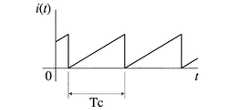
上述の変位測定装置では、特許文献1のように干渉光学系において単一の波長だけを用いるよりも、レーザ光の波長を連続的に変化させ、被対象物の変位を干渉光による位相のずれとして捕えた方が、より正確な変位の測定を行なうことが可能である。そこで従来は、半導体レーザの注入電流i(t)として図7に示すような鋸波状の変調電流を入力し、当該半導体レーザの発振周波数を変調して干渉信号を得るものが知られていた。 In the above-described displacement measuring apparatus, rather than using only a single wavelength in the interference optical system as in
ところが、半導体レーザに入力する変調電流の周波数fcが高くなり、図7に示す注入電流i(t)の周期Tcが4μSec(fc=250kHz)程度になると、鋸波の急激な立下りの部分において、変調に対応した干渉信号が得られなくなり、より高速な変位の測定ができないという問題を有していた。 However, when the frequency fc of the modulation current input to the semiconductor laser is increased and the cycle Tc of the injection current i (t) shown in FIG. 7 is about 4 μSec (fc = 250 kHz), at the portion where the sawtooth wave suddenly falls. The interference signal corresponding to the modulation cannot be obtained, and there is a problem that the displacement cannot be measured at a higher speed.
そこで本発明は上記問題点に鑑み、従来よりも高速に、被対象物の変位を正確に測定することができるレーザ干渉変位測定方法およびレーザ干渉変位測定装置を提供することをその目的とする。 In view of the above problems, an object of the present invention is to provide a laser interference displacement measuring method and a laser interference displacement measuring apparatus capable of accurately measuring the displacement of an object at a higher speed than before.
請求項1におけるレーザ干渉変位測定方法は、正弦波状に変調した注入電流をレーザ光源に入力し、波長を時間的に変化させながら当該レーザ光源から光を発生させる第1の工程と、前記光を分割して被対象物の表面と参照面に各々反射させた後、前記被対象物表面からの物体光と前記参照面からの参照光を合成して干渉光を得る第2の工程と、前記干渉光を電気的な干渉信号に変換する第3の工程と、前記正弦波状の変調周波数を基準として一定間隔で前記干渉信号をサンプリング取得し、このサンプリング取得した信号を演算処理して前記被対象物の変位を測定する第4の工程と、を含むことを特徴としている。 The laser interference displacement measuring method according to
この場合、正弦波状に変調した注入電流をレーザ光源に入力することで、レーザ光源から発生する光の波長も正弦波状に変化する。当該レーザ光源からの光は、被対象物の表面と参照面に各々反射して干渉し、この干渉光が電気的な干渉信号に変換されるが、レーザ光源に入力する注入電流は、急激な立上がりや立下りのない正弦波状の変化を繰り返すため、注入電流の変調周波数が例えば1.5MHz程度にまで高くなっても、干渉信号を正しくサンプリング取得することができる。そのため、正弦波状の変調周波数を基準として、被対象物の変位する時間よりも短い間隔で干渉信号をサンプリング取得すれば、当該サンプリング取得した複数の干渉信号の演算処理により、被対象物の変位を正しく測定することができる。 In this case, the wavelength of light generated from the laser light source also changes to a sine wave by inputting an injection current modulated in a sine wave form into the laser light source. Light from the laser light source reflects and interferes with the surface of the object and the reference surface, respectively, and this interference light is converted into an electrical interference signal, but the injection current input to the laser light source is abrupt. Since the sinusoidal change without rising or falling is repeated, the interference signal can be correctly sampled and acquired even when the modulation frequency of the injected current is increased to, for example, about 1.5 MHz. Therefore, if the interference signal is sampled and acquired at an interval shorter than the displacement time of the object with reference to the sinusoidal modulation frequency, the displacement of the object is calculated by arithmetic processing of the plurality of interference signals obtained by sampling. It can be measured correctly.
そして、このような作用効果は、レーザ光源からの光を分割して被対象物の表面と参照面に各々反射させた後、前記被対象物表面からの物体光と前記参照面からの参照光を合成して干渉光を得る干渉光学系と、前記干渉光学系により得られる干渉光を電気的な干渉信号に変換する第1の光電変換手段と、前記レーザ光源に正弦波状に変調した注入電流を与え、波長が時間的に変化する光を前記レーザ光源から発生させる変調電流生成手段と、前記正弦波状の変調周波数を基準として一定間隔で前記干渉信号をサンプリング取得し、このサンプリング取得した信号を演算処理して前記被対象物の変位を測定する信号処理手段と、を備えた請求項5のレーザ干渉変位測定装置でも実現できる。 Such an effect is obtained by dividing the light from the laser light source and reflecting the light on the surface of the object and the reference surface, respectively, and then the object light from the surface of the object and the reference light from the reference surface. An interference optical system that obtains interference light by combining the above, first photoelectric conversion means for converting the interference light obtained by the interference optical system into an electrical interference signal, and an injection current that is modulated into a sinusoidal shape in the laser light source A modulation current generating means for generating a light whose wavelength changes with time from the laser light source, and sampling and acquiring the interference signal at regular intervals with reference to the sinusoidal modulation frequency. The laser interference displacement measuring apparatus according to claim 5, further comprising a signal processing unit that performs arithmetic processing to measure the displacement of the object.
請求項2におけるレーザ干渉変位測定方法は、前記レーザ光源の光強度変化を電気的な検出信号に変換する第5の工程と、前記第3の工程における干渉信号を前記検出信号で除算し、時間的な光強度変化を除去した干渉信号を得る第6の工程と、をさらに含み、前記第4の工程は、前記第6の工程で得た時間的な光強度変化を除去した干渉信号をサンプリング取得することを特徴としている。 The laser interference displacement measuring method according to
正弦波状に変調した注入電流をレーザ光源に入力すると、レーザ光源からの光の波長だけでなく強度も時間と共に変化する。そこで、このレーザ光源の光強度変化を電気的な検出信号に変換し、別の干渉光から得られた干渉信号を当該検出信号で除算して、時間的な光強度変化を除去した干渉信号を得るようにすれば、被対象物の変位測定にとって不必要なレーザ光源の光強度変化の影響を、効果的に排除することができる。 When an injection current modulated into a sine wave is input to the laser light source, not only the wavelength of light from the laser light source but also the intensity changes with time. Therefore, the change in the light intensity of this laser light source is converted into an electrical detection signal, the interference signal obtained from another interference light is divided by the detection signal, and the interference signal from which the temporal light intensity change has been removed is obtained. If it obtains, the influence of the light intensity change of the laser light source unnecessary for the displacement measurement of the object can be effectively eliminated.
そして、このような作用効果は、前記レーザ光源の光強度変化を電気的な検出信号に変換する第2の光電変換手段と、前記第1の光電変換手段で得た干渉信号を前記第2の光電変換手段で得た検出信号で除算し、時間的な光強度変化を除去した干渉信号を得る割算器と、をさらに備えた請求項6のレーザ干渉変位測定装置でも実現できる。 Such an effect is achieved by the second photoelectric conversion means for converting the light intensity change of the laser light source into an electrical detection signal, and the interference signal obtained by the first photoelectric conversion means as the second photoelectric conversion means. The laser interference displacement measuring apparatus according to claim 6, further comprising a divider that divides the detection signal obtained by the photoelectric conversion means and obtains an interference signal from which temporal light intensity change is removed.
請求項3におけるレーザ干渉変位測定方法は、前記注入電流i(t)が次のように表され、 In the laser interference displacement measuring method according to

(但し、I0は電流基準値であると共に、a,ωc,tはそれぞれ、正弦波状変調の振幅,角周波数,時間である。)
前記レーザ光源の波長λ(t)が、次のように表され、(However, I0 is a current reference value, and a, ωc and t are the amplitude, angular frequency and time of sinusoidal modulation, respectively.)
The wavelength λ (t) of the laser light source is expressed as follows:
(但し、λ0は中心波長、βは変調効率である。)
さらに前記時間的な光強度変化を除去した干渉信号SD(t)が、次のように表されるときに、(However, λ0 is the center wavelength and β is the modulation efficiency.)
Further, when the interference signal SD (t) from which the temporal light intensity change is removed is expressed as follows:
(但し、A,Bは定数、Zは変調振幅、αは位相で、前記参照面から前記被対象物の表面までの距離をPとすると、変調振幅Zと位相αは次のように表せる。)(However, A and B are constants, Z is a modulation amplitude, and α is a phase. If the distance from the reference surface to the surface of the object is P, the modulation amplitude Z and the phase α can be expressed as follows. )
前記第4の工程で、前記cosωCtが0,1/2,1,−1/2のときの干渉信号SD(t)の値S0,S1,S2,S3をそれぞれサンプリング取得し、これらの各値S0,S1,S2,S3から前記定数A,Bを消去して前記位相αを求め、被対象物の変位を測定することを特徴としている。In the fourth step, the values S0 , S1 , S2 , and S3 of the interference signal SD (t) when the cos ωC t is 0, 1/2, 1, −1/2 are sampled, respectively. Acquired and erases the constants A and B from these values S0 , S1 , S2 and S3 to obtain the phase α, and measures the displacement of the object.
この場合、注入電流i(t)は電流基準値I0を中心として正弦波状に変調され、レーザ光源の波長λ(t)も、λ0を中心波長として時間と共に正弦波状に変化する。ここで時間的な光強度変化を除去した干渉信号SD(t)の値を、cosωCtの値が0,1/2,1,−1/2の時点でそれぞれS0,S1,S2,S3として取得すれば、簡単な演算処理によって定数A,Bを消去して、距離Pに関連した位相αを求め、被対象物の変位を測定することが可能になる。In this case, the injection current i (t) is modulated in a sine wave shape with the current reference value I0 as the center, and the wavelength λ (t) of the laser light source also changes in a sine wave shape with time with the λ0 as the center wavelength. The value of the interference signal SD (t) which is wherein removing temporal light intensity change, cos .omegaC value of t is 0, 1 / 2,1, respectively at the point of-1 / 2 S 0, S 1 , If acquired as S2 and S3 , the constants A and B can be eliminated by a simple arithmetic processing, the phase α related to the distance P can be obtained, and the displacement of the object can be measured.
そして、このような作用効果は、前記cosωCtが0,1/2,1,−1/2のときの干渉信号SD(t)の値S0,S1,S2,S3をそれぞれサンプリング取得し、これらの各値S0,S1,S2,S3から前記定数A,Bを消去して前記位相αを求め、被対象物の変位を測定する信号処理手段を備えた請求項7のレーザ干渉変位測定装置でも実現できる。Such an effect is obtained by using the values S0 , S1 , S2 , S3 of the interference signal SD (t) when cosωC t is 0, 1/2, 1, −1/2. A signal processing unit is provided for sampling and acquiring, respectively, erasing the constants A and B from these values S0 , S1 , S2 and S3 to obtain the phase α, and measuring the displacement of the object. This can also be realized by the laser interference displacement measuring apparatus according to the seventh aspect.
請求項4におけるレーザ干渉変位測定方法は、前記第4の工程で、前記cosωCtが−1のときの干渉信号SD(t)の値S4をさらにサンプリング取得すると共に、(S4−S2)/(S3−S1)の値が0になるように前記振幅aを調整することによって、常にZ=πとするフィードバック制御を行なう第7の工程をさらに含んだことを特徴としている。The laser interferometric displacement measuring method in
この場合、前記干渉信号SD(t)の値S0,S1,S2,S3に加えて、cosωCtが−1のときの干渉信号SD(t)の値S4を取得し、(S4−S2)/(S3−S1)の値が0になるように振幅aの量をフィードバック制御すれば、変調振幅Zは位相αを求めるのに必要な条件である一定値(=π)となって、正確に被対象物の変位を測定することが可能になる。In this case, in addition to the valueS0, S1, S 2,S 3 of the interference signalS D (t), cosω C t is acquired interference signal S valueS 4 of theD (t) when the -1 If the amount of the amplitude a is feedback controlled so that the value of (S4 −S2 ) / (S3 −S1 ) becomes 0, the modulation amplitude Z is a necessary condition for obtaining the phase α. It becomes a constant value (= π), and the displacement of the object can be accurately measured.
そして、このような作用効果は、前記cosωCtが−1のときの干渉信号SD(t)の値S4をさらにサンプリング取得すると共に、(S4−S2)/(S3−S1)の値が0になるように前記振幅aを調整することによって、常にZ=πとするフィードバック制御を行なう信号処理手段を備えた請求項8のレーザ干渉変位測定装置でも実現できる。Such an effect is obtained by sampling the value S4 of the interference signal SD (t) when the cos ωC t is −1, and (S4 −S2 ) / (S3 −S). The laser interference displacement measuring apparatus according to claim 8 provided with signal processing means for performing feedback control that always sets Z = π by adjusting the amplitude a so that the value of1 ) becomes 0.
請求項1のレーザ干渉変位測定方法及び請求項5のレーザ干渉変位測定装置によれば、注入電流の変調周波数が高くなっても、干渉信号を正しくサンプリング取得することが可能になり、従来よりも高速に被対象物の変位を正確に測定することができる。 According to the laser interference displacement measuring method of
請求項2のレーザ干渉変位測定方法及び請求項6のレーザ干渉変位測定装置によれば、被対象物の変位測定にとって不必要なレーザ光源の光強度変化の影響を、効果的に排除することができる。 According to the laser interference displacement measuring method of
請求項3のレーザ干渉変位測定方法及び請求項7のレーザ干渉変位測定装置によれば、簡単な演算処理によって定数A,Bを消去して、距離Pに関連した位相αを求め、被対象物の変位を測定することが可能になる。 According to the laser interference displacement measuring method of
請求項4のレーザ干渉変位測定方法及び請求項8のレーザ干渉変位測定装置によれば、変調振幅Zが位相αを求めるのに必要な条件であるZ=πの一定値となるため、正確に被対象物の変位を測定することが可能になる。 According to the laser interference displacement measuring method of
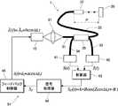
以下、本発明に係るレーザ干渉計を利用した変位測定方法および変位測定装置の好ましい実施例について、添付図面を参照しながら詳しく説明する。装置の全体構成を示す図1において、1はフィゾー型の干渉光学系を構成するレーザ干渉計であり、このレーザ干渉計1は、レーザ光源である半導体レーザ10と、半導体レーザ10からの出射光を集光するレンズ21と、光路を形成するファイバ31〜34およびファイバカプラ35と、ファイバ32の先端に連結され、被対象物Oの表面に対向して配置されるセルフォックレンズ22と、をそれぞれ備えている。前記ファイバ31〜34は、いずれもその基端が光の分離・結合機能を有するファイバカプラ35に連結され、ファイバ31の先端が前記レンズ21に対向配置される一方で、ファイバ33,34の先端には光電変換手段であるフォトダイオード41,42がそれぞれ連結される。なお、この実施例では光路中に光ファイバ31〜34を配設することにより、セルフォックレンズ22やフォトダイオード41,42などを自由な位置に配置できる柔軟な干渉光学系を構成しているが、ファイバ31〜34を用いない干渉光学系であってもよい。 Hereinafter, preferred embodiments of a displacement measuring method and a displacement measuring apparatus using a laser interferometer according to the present invention will be described in detail with reference to the accompanying drawings. In FIG. 1 showing the overall configuration of the apparatus,
本実施例におけるレーザ干渉計1は、半導体レーザ10からの出射光がレンズ21によりファイバ31の端面に集光され、当該ファイバ31を通してファイバカプラ35によりファイバ32,33へとそれぞれ分配される。ここで、ファイバ32の通過光はセルフォックレンズ22が取り付けられた参照面としての出射端面で一部が反射し、参照光となる。また、セルフォックレンズ22を通過した光は平行光となって被対象物Oの表面を照射し、この被対象物Oの表面からの反射光が物体光としてセルフォックレンズ22に戻る。ファイバ32,ファイバカプラ35およびファイバ34は、前記物体光と参照光との共通する伝送路となり、ファイバ34の端面に配置されたフォトダイオード41の検出面上に、これらの物体光および参照光が干渉するようになっている。一方、前記ファイバカプラ35による分配されたファイバ33の通過光は、別なフォトダイオード41の検出面上に達するようになっている。 In the
前記フォトダイオード41は、前記物体光と参照光との干渉光を検出面に取り込み、干渉信号S(t)を得る第1の光電変換手段に相当する。また別のフォトダイオード42は、ファイバカプラ35により分配された半導体レーザ10からの出射光の一部を検出面に取り込み、半導体レーザ10の時間的な光強度変化I(t)を表す検出信号を得る第2の光電変換手段に相当する。これらのフォトダイオード41,42で検出された各電気信号は、何れも後述する割算器43にそれぞれ入力される。 The
51は、フォトダイオード41,42からの各検出結果に基づいて、半導体レーザ10の注入電流i(t)を制御するフィードバック制御装置である。このフィードバック制御装置51は、前記フォトダイオード41により検出される干渉信号S(t)を、時間的な光強度変化I(t)を表す検出信号で除算することにより、時間的な光強度変化I(t)の影響を除去した干渉信号SD(t)を出力する割算器43と、割算器43から出力される干渉信号SD(t)の位相αを求め、ファイバ32の出射端面と被対象物Oの表面との間の距離Pの変化、すなわち被対象物Oの変位量を算出すると共に、前記干渉信号SD(t)に含まれる変調振幅Zの変化を検出し、その変化に応じたフィードバック信号SFを生成する信号処理器44と、半導体レーザ10の発振波長が正弦波状に変化するような注入電流i(t)を生成し、かつ前記フィードバック信号SFにより、距離Pの変化に対して干渉信号SD(t)の変調振幅Zが一定に保たれるように、半導体レーザ10の注入電流i(t)の振幅aをフィードバック制御するフィードバック制御器45と、により構成される。
なお、上記構成の変位測定装置において、レーザ干渉計1は、半導体レーザ10からの出射光と、被対象物Oの表面からの反射光との干渉光をフォトダイオード41で検出する一方で、前記半導体レーザ10の光強度変化を別なフォトダイオード42で検出できるあらゆる干渉光学系に適用できる。また、ここでの光電変換素子は、時間変化する光強度を短時間で測定できればよいので、フォトダイオード41,42のような追従性のよい単独の光電変換素子を用いるのが好ましい。 In the displacement measuring apparatus configured as described above, the
次に、上記構成についてその動作原理を説明する。先ず、半導体レーザ10の発振波長を角周波数ωcで正弦波状に変調するために、フィードバック制御器45は半導体レーザ10に対し次の数13のような注入電流i(t)を印加する。Next, the operation principle of the above configuration will be described. First, in order to modulate the sinusoidal oscillation wavelength at the angular frequency omegac of the
上式において、I0は電流基準値、aは振幅、tは時間であり、半導体レーザ10への注入電流i(t)は、時間tにより上限値I0+aと下限値I0−aの範囲で正弦波状に変化する。また、変調効率をβとすると、前記注入電流i(t)が与えられた半導体レーザ10の波長λ(t)は、次の数14のように表され、これも時間tにより上限値λ0+βaと下限値λ0−βaの範囲で正弦波状に変化する。一例として、注入電流i(t)を80±1mA変化させた場合の、半導体レーザ10の波長λ(t)(ひいては位相)のシフト量は0.02nm程度である。In the above equation, I0 is the current reference value, a is the amplitude, and t is the time, and the injection current i (t) to the
上記数14において、λ0は中心波長である。半導体レーザ10は上式のように、波長λ(t)すなわち発振周波数が時間的に変化するが、その光出力強度にも時間的変化が生じている。この時間的な光強度の変化は被対象物Oの変位測定にとって邪魔になるので、後段のフィードバック制御装置51に設けられた割算器43で除去する。In Equation 14, λ0 is the center wavelength. In the
前記レーザ干渉計1において、注入電流i(t)が与えられた半導体レーザ10からレーザ光が出射されると、この出射光がレンズ21によりファイバ31の端面に集光され、ファイバカプラ35の内部でファイバ32,33にそれぞれ分配される。ファイバ33を通過する光は、そのままフォトダイオード42の検出面に達し、半導体レーザ10の時間的な光強度変化I(t)を示す検出信号に変換される。一方、ファイバ32を通過する光は、ファイバ32の出射端面で一部が反射して参照光となるが、残りの光はセルフォックレンズ22を通過し、平行光となって被対象物Oの表面に到達する。この被対象物Oの表面で反射した光は、物体光として参照光と共にセルフォックレンズ22からファイバ32を逆戻りし、ファイバ34を通過してフォトダイオード41の検出面上で干渉する。フォトダイオード41は、この干渉光を干渉信号S(t)に変換して出力する。 In the
フィードバック制御装置51を構成する信号処理器44は、セルフォックレンズ22から被対象物Oの表面に至る距離Pの変化を、フォトダイオード41で検出した干渉信号S(t)から測定する。但し、干渉信号S(t)の振幅には半導体レーザ10の時間的な光強度変化I(t)の影響を受けているため、信号処理器44における測定の前段階として、割算器43により干渉信号S(t)を時間的な光強度変化I(t)で除算し、時間的な光強度変化I(t)の影響を除去した干渉信号SD(t)を得る。この干渉信号SD(t)は、次の数15で表わせる。The
なお、上式においてAおよびBは定数である。また、Zは変調振幅、αは従来の位相であり、それぞれ次の数16のように表わせる。 In the above formula, A and B are constants. Z is the modulation amplitude and α is the conventional phase, which can be expressed as in the following equation (16).
図2は、前記数15における変調周波数成分ZcosωCtの信号をグラフで示したもので、当該ZcosωCtの値はZ〜−Zの範囲を正弦波状に変化する。ここでのフィードバック制御装置51は、変調周波数の1周期に対し8分の1の間隔(ωCt=π/4毎)で、干渉信号SD(t)をサンプリング取得するのが好ましい。具体的には、図2に示すように、cosωCt=0における干渉信号の値S0と、cosωCt=1/2における干渉信号の値S1と、cosωCt=1における干渉信号の値S2と、cosωCt=−1/2における干渉信号の値S3と、cosωCt=−1における干渉信号の値S4を各々検出する。このとき、干渉信号S0〜S4の値は、次のようになる。FIG. 2 is a graph showing the signal of the modulation frequency component Zcos ωC t in Equation 15, and the value of Z cos ωC t changes in the range of Z to −Z in a sine wave shape. The
ここで、Z=πのときには、SC=S0−S2=2Bcosαとなり、SS=S3−S1=2Bsinαとなるので、SCとSSの各値から定数Bを消去して位相αを求め、上記数16の位相αと距離Pの関係から、被対象物Oの変位を測定することができる。また、前記変調振幅Zは、数4に示すように距離Pによって変化するため、距離Pが変化しても変調振幅Zの値が一定となるように(好ましくはZ=πとなって、信号処理器44により位相αが正確に求められるように)、信号処理器44は前記サンプリングされた干渉信号SD(t)の各値から、半導体レーザ10に対する注入電流i(t)の振幅aを可変制御するフィードバック信号SFを生成する。Here, when Z = [piis, S C = S 0 -S 2 = 2Bcosαnext, since theS S = S 3 -S 1 = 2Bsinα, to clear the constant B from each value ofS C andS S The phase α is obtained, and the displacement of the object O can be measured from the relationship between the phase α and the distance P in the above equation (16). Further, since the modulation amplitude Z changes with the distance P as shown in
このフィードバック信号SFの生成手順は次のようになる。まず、サンプリングで検出した干渉信号の値S1〜S4を利用して、SZ=S4−S2と、SSZ=S3−S1の各値を算出する。SZおよびSSZの各値は、上記数17から次のように導き出せる。Procedure for generating the feedback signal SF is as follows. First, each value of SZ = S4 -S2 and SSZ = S3 -S1 is calculated using interference signal values S1 to S4 detected by sampling. Each value of SZ and SSZ can be derived from Equation 17 as follows.
次に、SSZ≠0であれば、SZの値をSSZの値で除算したフィードバック信号SFを得る。すなわち、フィードバック信号SFは次の数式のようになる。Then, ifS SZ ≠ 0, to obtain a feedback signalS F which is obtained by dividing the value ofS Z by the value ofS SZ. That is, the feedback signalSF is represented by the following formula.
したがって、フィードバック信号SF=0となるように、半導体レーザ10の注入電流i(t)をフィードバック制御すれば、距離Pの変化に拘らずZ=πの関係が保たれて、前記SCとSSの各値から位相αを正しく算出することが可能になる。Therefore, if feedback control is performed on the injection current i (t) of the
上記位相αの算出を可能にするフィードバック制御装置51の一例を、図3に示す。同図において、好ましい構成の信号処理器44は、変調周波数の1周期に対し8分の1の間隔で干渉信号SD(t)をサンプリング取得するサンプリング手段61と、このサンプリング手段61で取得した干渉信号の各値S0〜S3から位相αを求め、被対象物Oの変位量を算出する変位量算出手段62と、距離Pが変化しても変調振幅Zの値が一定となるように、半導体レーザ10に対する注入電流i(t)の振幅aを調整する注入電流調整手段63と、を備えている。An example of the
より具体的には、サンプリング手段61は、半導体レーザ10の波長λ(t)を正弦波状に変調させる際のcosωCtの値が0,1/2,1,−1/2,−1の時点(例えば、変調周波数の位相が0,π/4,π/2,3π/4,πの時点)で、干渉信号SD(t)の値をそれぞれ、S0,S1,S2,S3,S4としてサンプリング取得するものである。また、変位量算出手段62は、前記S0およびS2の各値から、SC(=S0−S2)の値を算出する第1の減算手段65と、S1およびS3の各値から、SS(=S3−S1)の値を算出する第2の減算手段66と、SCとSSの各値から定数Bを消去して位相αを求め、上記数4の位相αと距離Pの関係から、被対象物Oの変位を算出する変位量演算手段67とを備えている。さらに、注入電流調整手段63は、前記S2およびS4の各値から、SZ(=S4−S2)の値を算出する第3の減算手段68と、S1およびS3の各値から、SSZ(=S3−S1)の値を算出する第4の減算手段69と、SSZが0でない時に、フィードバック信号SF(=SZ/SSZ)の値を算出する割算手段70と、この割算手段70で得たフィードバック信号SFの値が0になるように、最適な振幅aの値を算出する振幅量演算手段71とを備えている。なお、第2の減算手段66と第4の減算手段69は同じ値(S3−S1)を算出するものであるため、共通の減算手段で構成してもよい。また、変位量演算手段67で得た被対象物Oの変位量は、表示手段,印刷手段または報知手段などに任意の形態で出力される。More specifically, the sampling means 61 has values of cosωC t of 0, 1/2, 1, −1/2, −1 when modulating the wavelength λ (t) of the
次に、本実施例の変位測定装置を利用した実験結果の一例を提示する。なお、実験では被対象物Oを擬似的に変位させるために、PZTなどの圧電素子を被対象物Oに取り付けた。また、使用した半導体レーザ10の中心波長λ0は690nm,光出力は25mWであった。ファイバ32の出射端面と被対象物Oの表面との間の距離Pを25mmにまで近づけた場合に、Z=πの関係が保たれる正弦波位相変調の周波数が、fc=ωC/2πの上限値となる。現在の実験では、上限変調周波数fc=1.5MHz程度である。位相αの値は、前記サンプリングした干渉信号の値S0〜S3を利用して求められるので、測定時間は上限変調周波数fcの3/8周期(0.25μSec)、すなわち周波数に換算すると、(8/3)×fc=4MHzとなり、従来よりも遥かに短い時間で、被対象物Oの変位を正しく測定できることになる。Next, an example of an experimental result using the displacement measuring apparatus of the present embodiment is presented. In the experiment, a piezoelectric element such as PZT was attached to the object O in order to displace the object O in a pseudo manner. The
前記距離Pが50mmのときに、Z=πとなる干渉信号SD(t)が得られるように、注入電流i(t)の振幅aを調整し、そのときフィードバック信号SF=0になることを確認した。また、距離Pを40mm〜60mmの範囲で変化させたときに、フィードバック制御によりフィードバック信号SF=0が保たれることも確認した。When the distance P is 50 mm, the amplitude a of the injection current i (t) is adjusted so that an interference signal SD (t) where Z = π is obtained, and at that time, the feedback signal SF = 0. It was confirmed. It was also confirmed that the feedback signal SF = 0 was maintained by feedback control when the distance P was changed in the range of 40 mm to 60 mm.
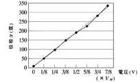
実験では、被対象物Oに取り付けた圧電素子に対し、0〜VMまでVM/8ずつ段階的に電圧を加えてゆき、距離Pにλ0/16毎の変化を与え、位相αを0〜2πの範囲で測定した。図4〜図6は、距離Pが40mm,50mm,60mmのときの位相αの測定結果をそれぞれ示している。図中、実線は理論値で、プロットが実験値である。実験値と理論値との差異から測定精度を求めた結果、距離P=50mmの場合は±10nm,距離P=40mmの場合は±18nm,距離P=60mmの場合は±20nmであった。In the experiment, to a piezoelectric element attached to the object O, Yuki added stepwise voltage by VM / 8 to 0 to VM, given a change in each lambda0/16 at a distance P, and the phase α It measured in the range of 0-2π. 4 to 6 show measurement results of the phase α when the distance P is 40 mm, 50 mm, and 60 mm, respectively. In the figure, the solid line is the theoretical value, and the plot is the experimental value. As a result of obtaining the measurement accuracy from the difference between the experimental value and the theoretical value, it was ± 10 nm when the distance P = 50 mm, ± 18 nm when the distance P = 40 mm, and ± 20 nm when the distance P = 60 mm.
実際は、1.5MHzの高い変調周波数と、変調振幅Zを一定とするフィードバック制御を行なうことにより、距離Pが20mm〜100mmの位置にある被対象物Oの変位を、0.25μSecの短い測定時間で、10nmの高い精度で測定することが可能になる。 Actually, by performing feedback control with a high modulation frequency of 1.5 MHz and a constant modulation amplitude Z, the displacement of the object O at a position where the distance P is 20 mm to 100 mm can be measured in a short measurement time of 0.25 μSec. It becomes possible to measure with high accuracy of 10 nm.
以上のように、本実施例におけるレーザ干渉変位測定方法は、正弦波状に変調した注入電流i(t)をレーザ光源10に入力し、波長λ(t)を時間的に変化させながら当該レーザ光源10から光(コヒーレンス光)を発生させる第1の工程と、前記光を分割して被対象物Oの表面と参照面であるファイバ32の出射端面に各々反射させた後、被対象物Oの表面からの物体光とファイバ32の出射端面からの参照光とを合成して、干渉光を得る第2の工程と、前記干渉光を電気的な干渉信号S(t)に変換する第3の工程と、前記正弦波状の変調周波数を基準として、前記第3の工程で得た干渉信号S(t)を一定間隔でサンプリング取得し、このサンプリング取得した信号を演算処理して被対象物Oの変位を測定する第4の工程と、を含んでいる。 As described above, in the laser interference displacement measuring method in this embodiment, the injection current i (t) modulated in a sine wave shape is input to the
またこの方法を実現するために、本実施例では、レーザ光源10からの光を分割して被対象物Oの表面とファイバ32の出射端面に各々反射させた後、被対象物Oの表面からの物体光とファイバ32の出射端面からの参照光とを合成して、干渉光を得る干渉光学系としてのレーザ干渉計1と、レーザ干渉計1により得られる干渉光を電気的な干渉信号S(t)に変換する第1の光電変換手段としてのフォトダイオード41と、レーザ光源10に正弦波状に変調した注入電流i(t)を与え、波長λ(t)が時間的に変化する光をレーザ光源10から発生させる変調電流生成手段としてのフィードバック制御器45と、前記正弦波状の変調周波数を基準として、一定間隔で前記干渉信号S(t)をサンプリング取得し、このサンプリング取得した信号を演算処理して被対象物Oの変位を測定する信号処理手段としての信号処理器44と、を備えたレーザ干渉変位測定装置を提供している。 In order to realize this method, in the present embodiment, the light from the
上記方法及び装置によれば、正弦波状に変調した注入電流i(t)をレーザ光源10に入力することで、レーザ光源10から発生する光の波長λ(t)も正弦波状に変化したものとなる。レーザ光源10からの光は、被対象物Oの表面とファイバ32の出射端面に各々反射して干渉し、この干渉光がフォトダイオード41によって電気的な干渉信号S(t)に変換されるが、レーザ光源10に入力する注入電流i(t)は、急激な立上がりや立下りのない正弦波状の変化を繰り返すため、注入電流i(t)の変調周波数が例えば1.5MHz程度にまで高くなっても、干渉信号S(t)を正しくサンプリング取得することができる。そのため、正弦波状の変調周波数を基準として、被対象物Oの変位する時間よりも短い間隔で干渉信号S(t)をサンプリング取得すれば、このサンプリング取得した複数の干渉信号S(t)の演算処理により、被対象物Oの変位を正しく測定できる。 According to the above method and apparatus, when the injection current i (t) modulated in a sine wave is input to the
また、本実施例におけるレーザ干渉変位測定方法は、レーザ光源10の光強度変化I(t)を電気的な検出信号に変換する第5の工程と、前記第3の工程における干渉信号S(t)を第5の行程で得た検出信号で除算し、時間的な光強度変化I(t)を除去した干渉信号SD(t)を得る第6の工程と、をさらに含み、前記第4の工程は、第6の工程で得た時間的な光強度変化I(t)を除去した干渉信号SD(t)をサンプリング取得することを特徴としている。Further, the laser interference displacement measuring method in the present embodiment includes the fifth step of converting the light intensity change I (t) of the
同様に、本実施例におけるレーザ干渉変位測定装置は、レーザ光源10の光強度変化I(t)を電気的な検出信号に変換する第2の光電変換手段としてのフォトダイオード42と、 フォトダイオード41で得た干渉信号S(t)をフォトダイオード42で得た検出信号で除算し、時間的な光強度変化I(t)を除去した干渉信号SD(t)を得る割算手段としての割算器43と、をさらに備えている。Similarly, the laser interference displacement measuring apparatus according to the present embodiment includes a
この場合、正弦波状に変調した注入電流をレーザ光源10に入力すると、レーザ光源10からの光の波長λ(t)だけでなく強度も時間と共に変化する。そこで、このレーザ光源10の光強度変化I(t)をフォトダイオード42で電気的な検出信号に変換し、別のフォトダイオード41にて干渉光から得られた干渉信号を当該検出信号で除算して、時間的な光強度変化I(t)を除去した干渉信号SD(t)を得るようにすれば、被対象物Oの変位測定にとって不必要なレーザ光源10の光強度変化の影響を、効果的に排除することができる。In this case, when an injection current modulated in a sine wave shape is input to the
また、本実施例におけるレーザ干渉変位測定方法は、注入電流i(t)が前記数13のように表され、レーザ光源10の波長λ(t)が前記数14のように表され、時間的な光強度変化を除去した干渉信号SD(t)が数15のように表されるときに、前記第4の工程で、前記cosωCtが0,1/2,1,−1/2のときの干渉信号SD(t)の値S0,S1,S2,S3をそれぞれサンプリング取得し、これらの各値S0,S1,S2,S3から数15に含まれる定数A,Bを消去して、距離Pに関連した位相αを求め、被対象物Oの変位を測定することを特徴としている。Further, in the laser interference displacement measuring method in the present embodiment, the injection current i (t) is expressed by the above equation 13, the wavelength λ (t) of the
同様に、本実施例におけるレーザ干渉変位測定装置は、前記cosωCtが0,1/2,1,−1/2のときの干渉信号SD(t)の値S0,S1,S2,S3をそれぞれサンプリング取得し、これらの各値S0,S1,S2,S3から前記定数A,Bを消去して前記位相αを求め、被対象物Oの変位を測定するような信号処理器44を備えている。Similarly, in the laser interference displacement measuring apparatus in the present embodiment, the values S0 , S1 , S of the interference signal SD (t) when cosωC t is 0, 1/2, 1, −1/2.2 and S3 are sampled and acquired, the constants A and B are deleted from these values S0 , S1 , S2 and S3 to obtain the phase α, and the displacement of the object O is measured. Such a
この場合、注入電流i(t)は電流基準値I0を中心として正弦波状に変調され、レーザ光源の波長λ(t)も、λ0を中心波長として時間と共に正弦波状に変化する。ここで時間的な光強度変化を除去した干渉信号SD(t)の値を、cosωCtの値が0,1/2,1,−1/2の時点でそれぞれS0,S1,S2,S3として取得すれば、簡単な演算処理によって定数A,Bを消去して、距離Pに関連した位相αを求め、被対象物Oの変位を測定することが可能になる。In this case, the injection current i (t) is modulated in a sine wave shape with the current reference value I0 as the center, and the wavelength λ (t) of the laser light source also changes in a sine wave shape with time with the λ0 as the center wavelength. The value of the interference signal SD (t) which is wherein removing temporal light intensity change, cos .omegaC value of t is 0, 1 / 2,1, respectively at the point of-1 / 2 S 0, S 1 , If acquired as S2 and S3 , the constants A and B can be eliminated by a simple calculation process, the phase α related to the distance P can be obtained, and the displacement of the object O can be measured.
また、本実施例におけるレーザ干渉変位測定方法は、前記第4の工程で、前記cosωCtが−1のときの干渉信号SD(t)の値S4をさらにサンプリング取得すると共に、(S4−S2)/(S3−S1)の値が0になるように前記振幅aを調整することによって、常にZ=πとするフィードバック制御を行なう第7の工程をさらに含んだことを特徴としている
同様に、本実施例におけるレーザ干渉変位測定装置は、前記cosωCtが−1のときの干渉信号SD(t)の値S4をさらにサンプリング取得すると共に、(S4−S2)/(S3−S1)の値が0になるように前記振幅aを調整することによって、常にZ=πとするフィードバック制御を行なうような信号処理器44を備えている。Further, in the laser interference displacement measuring method in this embodiment, in the fourth step, the value S4 of the interference signal SD (t) when the cosωC t is −1 is further sampled and acquired (S by the value of4 -S 2) / (S 3 -S 1) is adjusted the amplitude a to be 0, always be further comprised seventh step of performing feedback control of the Z = [pi Similarly, the laser interference displacement measuring apparatus in the present embodiment further samples and acquires the value S4 of the interference signal SD (t) when the cos ωC t is −1, and (S4 -S2 ) A
この場合、前記干渉信号SD(t)の値S0,S1,S2,S3に加えて、cosωCtが−1のときの干渉信号SD(t)の値S4を取得し、フィードバック信号SF=(S4−S2)/(S3−S1)の値が0になるように、注入電流i(t)の振幅aの量をフィードバック制御すれば、変調振幅Zは位相αを求めるのに必要な条件である一定値(=π)となって、正確に被対象物Oの変位を測定することが可能になる。In this case, in addition to the valueS0, S1, S 2,S 3 of the interference signalS D (t), cosω C t is acquired interference signal S valueS 4 of theD (t) when the -1 If the amount of the amplitude a of the injection current i (t) is feedback-controlled so that the value of the feedback signalSF = (S4 -S2 ) / (S3 -S1 ) becomes 0, the modulation amplitude Z becomes a constant value (= π), which is a condition necessary for obtaining the phase α, and the displacement of the object O can be accurately measured.
なお、本発明は上記各実施例に限定されるものではなく、種々の変形実施が可能である。例えば注入電流i(t)を変化させることにより、その発振波長λ(t)が変化するものならば、半導体レーザ10以外の各種光源を利用することができる。また、割算器43としての機能を、信号処理器44に含ませてもよい。 In addition, this invention is not limited to said each Example, A various deformation | transformation implementation is possible. For example, various light sources other than the
1 レーザ干渉計(干渉光学系)
10 レーザ光源
41 フォトダイオード(第1の光電変換手段)
42 フォトダイオード(第2の光電変換手段)
43 割算器(割算手段)
44 信号処理器(信号処理手段)
45 フィードバック制御器(変調電流生成手段)
O 被対象物
1 Laser interferometer (interference optical system)
10 Laser light source
41 Photodiode (first photoelectric conversion means)
42 Photodiode (second photoelectric conversion means)
43 Divider (Division means)
44 Signal processor (Signal processing means)
45 Feedback controller (Modulation current generator)
O Object
Claims (8)
Translated fromJapanese前記光を分割して被対象物の表面と参照面に各々反射させた後、前記被対象物表面からの物体光と前記参照面からの参照光を合成して干渉光を得る第2の工程と、
前記干渉光を電気的な干渉信号に変換する第3の工程と、
前記正弦波状の変調周波数を基準として一定間隔で前記干渉信号をサンプリング取得し、このサンプリング取得した信号を演算処理して前記被対象物の変位を測定する第4の工程と、を含むことを特徴とするレーザ干渉変位測定方法。A first step of inputting a sinusoidally modulated injection current to a laser light source and generating light from the laser light source while changing the wavelength with time;
A second step of obtaining interference light by dividing the light and reflecting the light on the surface of the object and the reference surface, and then combining the object light from the surface of the object and the reference light from the reference surface When,
A third step of converting the interference light into an electrical interference signal;
And a fourth step of sampling and acquiring the interference signal at regular intervals with the sinusoidal modulation frequency as a reference, and calculating the displacement of the object by calculating and processing the sampled and acquired signal. A laser interference displacement measuring method.
前記第3の工程における干渉信号を前記検出信号で除算し、時間的な光強度変化を除去した干渉信号を得る第6の工程と、をさらに含み、
前記第4の工程は、前記第6の工程で得た時間的な光強度変化を除去した干渉信号をサンプリング取得することを特徴とするレーザ干渉変位測定方法。A fifth step of converting the light intensity change of the laser light source into an electrical detection signal;
A sixth step of dividing the interference signal in the third step by the detection signal to obtain an interference signal from which the temporal light intensity change is removed, and
In the fourth step, the interference signal obtained by sampling the interference signal from which the temporal change in light intensity obtained in the sixth step is sampled and acquired.
(但し、I0は電流基準値であると共に、a,ωc,tはそれぞれ、正弦波状変調の振幅,角周波数,時間である。)
前記レーザ光源の波長λ(t)が、次のように表され、
(但し、λ0は中心波長、βは変調効率である。)
さらに前記時間的な光強度変化を除去した干渉信号SD(t)が、次のように表されるときに、
(但し、A,Bは定数、Zは変調振幅、αは位相で、前記参照面から前記被対象物の表面までの距離をPとすると、変調振幅Zと位相αは次のように表せる。)
前記第4の工程で、前記cosωCtが0,1/2,1,−1/2のときの干渉信号SD(t)の値S0,S1,S2,S3をそれぞれサンプリング取得し、これらの各値S0,S1,S2,S3から前記定数A,Bを消去して前記位相αを求め、被対象物の変位を測定することを特徴とする請求項2記載のレーザ干渉変位測定方法。The injection current i (t) is expressed as follows:
(However, I0 is a current reference value, and a, ωc and t are the amplitude, angular frequency and time of sinusoidal modulation, respectively.)
The wavelength λ (t) of the laser light source is expressed as follows:
(However, λ0 is the center wavelength and β is the modulation efficiency.)
Further, when the interference signal SD (t) from which the temporal light intensity change is removed is expressed as follows:
(However, A and B are constants, Z is a modulation amplitude, and α is a phase. If the distance from the reference surface to the surface of the object is P, the modulation amplitude Z and the phase α can be expressed as follows. )
In the fourth step, the values S0 , S1 , S2 , and S3 of the interference signal SD (t) when the cos ωC t is 0, 1/2, 1, −1/2 are sampled, respectively.3. The obtained object is measured by erasing the constants A and B from these values S0 , S1 , S2 and S3 to determine the phase α and measuring the displacement of the object. The laser interference displacement measuring method as described.
(S4−S2)/(S3−S1)の値が0になるように前記振幅aを調整することによって、常にZ=πとするフィードバック制御を行なう第7の工程をさらに含むことを特徴とする請求項3記載のレーザ干渉変位測定方法。In the fourth step, the value S4 of the interference signal SD (t) when the cos ωC t is −1 is further sampled and acquired,
It further includes a seventh step of performing feedback control that always sets Z = π by adjusting the amplitude a so that the value of (S4 −S2 ) / (S3 −S1 ) becomes zero. The laser interference displacement measuring method according to claim 3.
前記干渉光学系により得られる干渉光を電気的な干渉信号に変換する第1の光電変換手段と、
前記レーザ光源に正弦波状に変調した注入電流を与え、波長が時間的に変化する光を前記レーザ光源から発生させる変調電流生成手段と、
前記正弦波状の変調周波数を基準として一定間隔で前記干渉信号をサンプリング取得し、このサンプリング取得した信号を演算処理して前記被対象物の変位を測定する信号処理手段と、を備えたことを特徴とするレーザ干渉変位測定装置。Interference to obtain interference light by dividing light from the laser light source and reflecting it to the surface of the object and the reference surface respectively, and then combining the object light from the object surface and the reference light from the reference surface Optical system,
First photoelectric conversion means for converting interference light obtained by the interference optical system into an electrical interference signal;
A modulation current generating means for applying a sinusoidally modulated injection current to the laser light source, and generating a light whose wavelength changes with time from the laser light source;
Signal processing means for sampling and acquiring the interference signal at regular intervals with the sinusoidal modulation frequency as a reference, and processing the sampled and acquired signal to measure the displacement of the object; Laser interference displacement measuring device.
前記第1の光電変換手段で得た干渉信号を前記第2の光電変換手段で得た検出信号で除算し、時間的な光強度変化を除去した干渉信号を得る割算手段と、をさらに備えたことを特徴とする請求項5記載のレーザ干渉変位測定装置。Second photoelectric conversion means for converting a light intensity change of the laser light source into an electrical detection signal;
Dividing means for dividing the interference signal obtained by the first photoelectric conversion means by the detection signal obtained by the second photoelectric conversion means to obtain an interference signal from which temporal light intensity change has been removed, further comprising 6. The laser interference displacement measuring apparatus according to claim 5, wherein
(但し、I0は電流基準値であると共に、a,ωc,tはそれぞれ、正弦波状変調の振幅,角周波数,時間である。)
前記レーザ光源の波長λ(t)が、次のように表され、
(但し、λ0は中心波長、βは変調効率である。)
さらに前記時間的な光強度変化を除去した干渉信号SD(t)が、次のように表されるときに、
(但し、A,Bは定数、Zは変調振幅、αは位相で、前記参照面から前記被対象物の表面までの距離をPとすると、変調振幅Zと位相αは次のように表せる。)
前記信号処理手段は、前記cosωCtが0,1/2,1,−1/2のときの干渉信号SD(t)の値S0,S1,S2,S3をそれぞれサンプリング取得し、これらの各値S0,S1,S2,S3から前記定数A,Bを消去して前記位相αを求め、被対象物の変位を測定するものであることを特徴とする請求項6記載のレーザ干渉変位測定装置。The injection current i (t) is expressed as follows:
(However, I0 is a current reference value, and a, ωc and t are the amplitude, angular frequency and time of sinusoidal modulation, respectively.)
The wavelength λ (t) of the laser light source is expressed as follows:
(However, λ0 is the center wavelength and β is the modulation efficiency.)
Further, when the interference signal SD (t) from which the temporal light intensity change is removed is expressed as follows:
(However, A and B are constants, Z is a modulation amplitude, and α is a phase. If the distance from the reference surface to the surface of the object is P, the modulation amplitude Z and the phase α can be expressed as follows. )
The signal processing means obtains sampling values S0 , S1 , S2 , and S3 of the interference signal SD (t) when the cos ωC t is 0, 1/2, 1, −1/2, respectively. Then, the constants A and B are deleted from these values S0 , S1 , S2 and S3 to obtain the phase α, and the displacement of the object is measured. Item 7. A laser interference displacement measuring apparatus according to Item 6.
Priority Applications (1)
| Application Number | Priority Date | Filing Date | Title |
|---|---|---|---|
| JP2004290013AJP4501000B2 (en) | 2004-10-01 | 2004-10-01 | Laser interference displacement measuring method and laser interference displacement measuring apparatus |
Applications Claiming Priority (1)
| Application Number | Priority Date | Filing Date | Title |
|---|---|---|---|
| JP2004290013AJP4501000B2 (en) | 2004-10-01 | 2004-10-01 | Laser interference displacement measuring method and laser interference displacement measuring apparatus |
Publications (2)
| Publication Number | Publication Date |
|---|---|
| JP2006105669Atrue JP2006105669A (en) | 2006-04-20 |
| JP4501000B2 JP4501000B2 (en) | 2010-07-14 |
Family
ID=36375599
Family Applications (1)
| Application Number | Title | Priority Date | Filing Date |
|---|---|---|---|
| JP2004290013AExpired - LifetimeJP4501000B2 (en) | 2004-10-01 | 2004-10-01 | Laser interference displacement measuring method and laser interference displacement measuring apparatus |
Country Status (1)
| Country | Link |
|---|---|
| JP (1) | JP4501000B2 (en) |
Cited By (12)
| Publication number | Priority date | Publication date | Assignee | Title |
|---|---|---|---|---|
| JP2009250786A (en)* | 2008-04-07 | 2009-10-29 | Mitsutoyo Corp | Laser interference length measuring apparatus and laser interference length measuring method |
| JP2010101642A (en)* | 2008-10-21 | 2010-05-06 | Yamatake Corp | Physical quantity sensor and physical quantity measurement method |
| JP2010117145A (en)* | 2008-11-11 | 2010-05-27 | Yamatake Corp | Physical quantity sensor and method for measuring physical quantity |
| JP2010127885A (en)* | 2008-12-01 | 2010-06-10 | Mitsutoyo Corp | Laser interferometer |
| JP2010164328A (en)* | 2009-01-13 | 2010-07-29 | Mitsutoyo Corp | Laser interferometer |
| KR101382004B1 (en) | 2013-04-03 | 2014-04-04 | 조선대학교산학협력단 | Low coherence interferometry using a frequency-modulated laser diode |
| US8982336B2 (en) | 2010-03-10 | 2015-03-17 | Azbil Corporation | Physical quantity sensor and physical quantity measuring method |
| US8996326B2 (en) | 2009-06-29 | 2015-03-31 | Azbil Corporation | Counting device, physical quantity sensor, counting method, and physical quantity measuring method |
| JP2016006397A (en)* | 2014-06-20 | 2016-01-14 | 大塚電子株式会社 | Dynamic light scattering measurement device and dynamic light scattering measurement method |
| CN109870677A (en)* | 2019-03-13 | 2019-06-11 | 西安工业大学 | An Amplitude Normalization Method for Frequency Modulated Continuous Wave Interference Signal |
| JP2019152614A (en)* | 2018-03-06 | 2019-09-12 | 中央精機株式会社 | Displacement measuring device |
| CN114894095A (en)* | 2022-03-04 | 2022-08-12 | 中国科学院合肥物质科学研究院 | Cantilever beam displacement measuring device and measuring method |
Citations (4)
| Publication number | Priority date | Publication date | Assignee | Title |
|---|---|---|---|---|
| JPS60203801A (en)* | 1984-03-28 | 1985-10-15 | Canon Inc | active interferometer |
| JPS6439505A (en)* | 1987-08-05 | 1989-02-09 | Matsushita Electric Industrial Co Ltd | Optical measuring instrument |
| JPH0835811A (en)* | 1991-12-16 | 1996-02-06 | Univ Qinghua | Frequency modulation optical fiber displacement measuring device |
| JPH09229626A (en)* | 1996-02-20 | 1997-09-05 | Nippon Soken Inc | Laser interference displacement meter |
- 2004
- 2004-10-01JPJP2004290013Apatent/JP4501000B2/ennot_activeExpired - Lifetime
Patent Citations (4)
| Publication number | Priority date | Publication date | Assignee | Title |
|---|---|---|---|---|
| JPS60203801A (en)* | 1984-03-28 | 1985-10-15 | Canon Inc | active interferometer |
| JPS6439505A (en)* | 1987-08-05 | 1989-02-09 | Matsushita Electric Industrial Co Ltd | Optical measuring instrument |
| JPH0835811A (en)* | 1991-12-16 | 1996-02-06 | Univ Qinghua | Frequency modulation optical fiber displacement measuring device |
| JPH09229626A (en)* | 1996-02-20 | 1997-09-05 | Nippon Soken Inc | Laser interference displacement meter |
Cited By (16)
| Publication number | Priority date | Publication date | Assignee | Title |
|---|---|---|---|---|
| JP2009250786A (en)* | 2008-04-07 | 2009-10-29 | Mitsutoyo Corp | Laser interference length measuring apparatus and laser interference length measuring method |
| JP2010101642A (en)* | 2008-10-21 | 2010-05-06 | Yamatake Corp | Physical quantity sensor and physical quantity measurement method |
| JP2010117145A (en)* | 2008-11-11 | 2010-05-27 | Yamatake Corp | Physical quantity sensor and method for measuring physical quantity |
| JP2010127885A (en)* | 2008-12-01 | 2010-06-10 | Mitsutoyo Corp | Laser interferometer |
| DE102010000817B4 (en) | 2009-01-13 | 2023-03-23 | Mitutoyo Corp. | laser interferometer |
| JP2010164328A (en)* | 2009-01-13 | 2010-07-29 | Mitsutoyo Corp | Laser interferometer |
| US8996326B2 (en) | 2009-06-29 | 2015-03-31 | Azbil Corporation | Counting device, physical quantity sensor, counting method, and physical quantity measuring method |
| US8982336B2 (en) | 2010-03-10 | 2015-03-17 | Azbil Corporation | Physical quantity sensor and physical quantity measuring method |
| KR101382004B1 (en) | 2013-04-03 | 2014-04-04 | 조선대학교산학협력단 | Low coherence interferometry using a frequency-modulated laser diode |
| JP2016006397A (en)* | 2014-06-20 | 2016-01-14 | 大塚電子株式会社 | Dynamic light scattering measurement device and dynamic light scattering measurement method |
| JP2019152614A (en)* | 2018-03-06 | 2019-09-12 | 中央精機株式会社 | Displacement measuring device |
| JP7048870B2 (en) | 2018-03-06 | 2022-04-06 | 中央精機株式会社 | Displacement measuring device |
| CN109870677B (en)* | 2019-03-13 | 2023-02-24 | 西安工业大学 | A method for normalizing amplitude of FM continuous wave interference signal |
| CN109870677A (en)* | 2019-03-13 | 2019-06-11 | 西安工业大学 | An Amplitude Normalization Method for Frequency Modulated Continuous Wave Interference Signal |
| CN114894095A (en)* | 2022-03-04 | 2022-08-12 | 中国科学院合肥物质科学研究院 | Cantilever beam displacement measuring device and measuring method |
| CN114894095B (en)* | 2022-03-04 | 2023-08-29 | 中国科学院合肥物质科学研究院 | Cantilever beam displacement measuring device and measuring method |
Also Published As
| Publication number | Publication date |
|---|---|
| JP4501000B2 (en) | 2010-07-14 |
Similar Documents
| Publication | Publication Date | Title |
|---|---|---|
| JP6638810B2 (en) | Defect inspection apparatus and method | |
| JP4501000B2 (en) | Laser interference displacement measuring method and laser interference displacement measuring apparatus | |
| Matsumoto et al. | Absolute measurement of baselines up to 403 m using heterodyne temporal coherence interferometer with optical frequency comb | |
| Azcona et al. | A nanometric displacement measurement system using differential optical feedback interferometry | |
| JP2001227911A (en) | Interference detection device, tomography device | |
| JPH10267631A (en) | Optical measuring device | |
| WO1998043068A1 (en) | Optical measuring instrument | |
| JP4963587B2 (en) | Laser Doppler vibrometer | |
| EP3877724B1 (en) | Method and device for in situ process monitoring | |
| JP4976924B2 (en) | Optical gas detection method and optical gas detection device | |
| JP2018059789A (en) | Distance measuring device and distance measuring method | |
| US10254306B2 (en) | Probe calibration or measurement routine | |
| JP6555712B2 (en) | Plane vibration measuring apparatus and plane vibration measuring method | |
| JP2000275107A5 (en) | ||
| TWI880926B (en) | Non-contact wafer thickness measurement device | |
| JP7315535B2 (en) | Vibration measuring device | |
| JP7061364B2 (en) | Distance measuring device and distance measuring method | |
| JP6341325B2 (en) | Stage position control device | |
| TWI403687B (en) | Displacement measuring device and its measuring method | |
| JP7612155B2 (en) | Measurement system and method | |
| JP6172465B2 (en) | Stage position control apparatus and method | |
| JP6554755B2 (en) | Vibration measuring apparatus and vibration measuring method | |
| JP2993836B2 (en) | Interferometer using coherence degree | |
| Wang et al. | A self-mixing laser diode for micro-displacement measurement | |
| Leun | Features of high-precision measurements of laser beam lateral displacements in hybrid 3D scanning fiber-optic measuring heads |
Legal Events
| Date | Code | Title | Description |
|---|---|---|---|
| A621 | Written request for application examination | Free format text:JAPANESE INTERMEDIATE CODE: A621 Effective date:20061228 | |
| A977 | Report on retrieval | Free format text:JAPANESE INTERMEDIATE CODE: A971007 Effective date:20090130 | |
| A131 | Notification of reasons for refusal | Free format text:JAPANESE INTERMEDIATE CODE: A131 Effective date:20090205 | |
| A521 | Request for written amendment filed | Free format text:JAPANESE INTERMEDIATE CODE: A523 Effective date:20090324 | |
| TRDD | Decision of grant or rejection written | ||
| A01 | Written decision to grant a patent or to grant a registration (utility model) | Free format text:JAPANESE INTERMEDIATE CODE: A01 Effective date:20100329 | |
| A01 | Written decision to grant a patent or to grant a registration (utility model) | Free format text:JAPANESE INTERMEDIATE CODE: A01 | |
| R150 | Certificate of patent or registration of utility model | Ref document number:4501000 Country of ref document:JP Free format text:JAPANESE INTERMEDIATE CODE: R150 Free format text:JAPANESE INTERMEDIATE CODE: R150 | |
| EXPY | Cancellation because of completion of term |