JP2006105640A - Navigation device - Google Patents
Navigation deviceDownload PDFInfo
- Publication number
- JP2006105640A JP2006105640AJP2004289513AJP2004289513AJP2006105640AJP 2006105640 AJP2006105640 AJP 2006105640AJP 2004289513 AJP2004289513 AJP 2004289513AJP 2004289513 AJP2004289513 AJP 2004289513AJP 2006105640 AJP2006105640 AJP 2006105640A
- Authority
- JP
- Japan
- Prior art keywords
- image
- camera
- information
- detection means
- terminal
- Prior art date
- Legal status (The legal status is an assumption and is not a legal conclusion. Google has not performed a legal analysis and makes no representation as to the accuracy of the status listed.)
- Pending
Links
Images


Classifications
- G—PHYSICS
- G01—MEASURING; TESTING
- G01C—MEASURING DISTANCES, LEVELS OR BEARINGS; SURVEYING; NAVIGATION; GYROSCOPIC INSTRUMENTS; PHOTOGRAMMETRY OR VIDEOGRAMMETRY
- G01C21/00—Navigation; Navigational instruments not provided for in groups G01C1/00 - G01C19/00
- G01C21/20—Instruments for performing navigational calculations
- G—PHYSICS
- G01—MEASURING; TESTING
- G01C—MEASURING DISTANCES, LEVELS OR BEARINGS; SURVEYING; NAVIGATION; GYROSCOPIC INSTRUMENTS; PHOTOGRAMMETRY OR VIDEOGRAMMETRY
- G01C21/00—Navigation; Navigational instruments not provided for in groups G01C1/00 - G01C19/00
- G01C21/26—Navigation; Navigational instruments not provided for in groups G01C1/00 - G01C19/00 specially adapted for navigation in a road network
- G01C21/28—Navigation; Navigational instruments not provided for in groups G01C1/00 - G01C19/00 specially adapted for navigation in a road network with correlation of data from several navigational instruments
- G01C21/30—Map- or contour-matching
Landscapes
- Engineering & Computer Science (AREA)
- Radar, Positioning & Navigation (AREA)
- Remote Sensing (AREA)
- Automation & Control Theory (AREA)
- Physics & Mathematics (AREA)
- General Physics & Mathematics (AREA)
- Navigation (AREA)
- Traffic Control Systems (AREA)
- Studio Devices (AREA)
- Mobile Radio Communication Systems (AREA)
- Instructional Devices (AREA)
Abstract
Translated fromJapaneseDescription
Translated fromJapanese本発明は、ナビゲーションシステムに係り、特に携帯端末を用いて歩行者の経路誘導を行うシステムに関する。 The present invention relates to a navigation system, and more particularly to a system for guiding a pedestrian using a mobile terminal.
直感的に分かり易いナビゲーションシステムを実現するため、任意の視点から3次元地図を眺めたときに得られる投影図を表示画面に表示する3次元地図表示のナビゲーション技術がある。そのような技術は、たとえば、特開2003−232639号公報で開示されている。3次元地図表示のナビゲーション装置を実現した場合、視点位置によっては、注目すべき地図構成物が他の地図構成物に隠れて表示されなくなることがある。このため、現在地や目的地、あるいは現在地と目的地とを結ぶ経路等、ユーザが知りたい情報が表示画面に表示されなくなることがあるという問題がある。前記公報では、公報で開示の技術により、地図構成物に隠れる位置にある情報を表示画面に表示することができる3次元地図表示を実現した地図表示装置及びナビゲーション装置を提供することを目的としている。 In order to realize an intuitive and easy-to-understand navigation system, there is a 3D map display navigation technology that displays a projection map obtained when viewing a 3D map from an arbitrary viewpoint on a display screen. Such a technique is disclosed in, for example, Japanese Patent Application Laid-Open No. 2003-232639. When a navigation device for displaying a three-dimensional map is realized, depending on the viewpoint position, a noticeable map component may be hidden behind other map components and may not be displayed. For this reason, there is a problem that information that the user wants to know, such as a current location, a destination, or a route connecting the current location and the destination, may not be displayed on the display screen. An object of the above publication is to provide a map display device and a navigation device that realizes a three-dimensional map display capable of displaying information on a display screen on a display screen by a technique disclosed in the publication. .
また、直感的に分かり易いナビゲーションシステムを実現する別の方法として、実写画像とナビゲーションのためのCG画像とを重ね合わせ表示する複合現実感(Mixed Reality)と呼ばれる技術がある。 As another method for realizing an intuitive and easy-to-understand navigation system, there is a technique called mixed reality, in which a real image and a CG image for navigation are superimposed and displayed.
さらに、特開平11−108684号公報で開示された技術は、自動車のノーズ等に取り付けた撮像カメラで進行方向の景色を撮像し、この背景画像に対して画像合成部によりナビゲーション情報要素を重ね合せて表示するというものである。これにより、グラフィックの表示だけに頼るより、運転者等は自動車の現在位置や進行経路等をより感覚的に把握できるようになることを狙っている。 Furthermore, the technique disclosed in Japanese Patent Application Laid-Open No. 11-108684 captures a scene in the traveling direction with an imaging camera attached to a nose of an automobile, and overlays navigation information elements on the background image by an image composition unit. Is displayed. In this way, rather than relying solely on graphic display, the driver or the like aims to be able to grasp the current position of the automobile, the traveling route, etc. more sensuously.
本発明は、直感的に分かり易いナビゲーションシステムを提供することを目的としている。ナビゲーションの例として歩行者について考えると、歩行者に直感的に分かり易いナビゲーションを提供するためには、歩行者が見るであろう現実世界の画像とナビゲーション画像との対応が直感的に取りやすければよいと考えられる。このため、本発明では、単に地理情報データベースにアクセスできるだけでなく、端末(スクリーン)の姿勢を検知し、端末がどのような姿勢にあろうとも、端末のスクリーンには歩行者が見るであろう現実世界に即したナビゲーション画像を表示することが必要である。 An object of the present invention is to provide an intuitive and easy-to-understand navigation system. Considering pedestrians as an example of navigation, in order to provide pedestrians with intuitive and easy-to-understand navigation, if the correspondence between real-world images that pedestrians would see and navigation images is intuitive It is considered good. For this reason, in the present invention, not only can the geographic information database be accessed, but the attitude of the terminal (screen) is detected and a pedestrian will see the terminal screen regardless of the attitude of the terminal. It is necessary to display a navigation image that matches the real world.
また、より直感的な案内を行うために、現実世界に即したCGを生成だけではなく、現実世界そのものの映像(実写画像)をカメラにより得て、この実写画像上に経路などのナビゲーションのためのCG画像を重ね合わせて表示する。この場合、カメラ付きの携帯端末は、歩行者の手に持って操作されることから、実写画像とCG画像とを正確に重ね合わせるためには、カメラ姿勢やスクリーンの姿勢の検知が重要となる。しかしながら、特開2003−232639号公報で開示の技術では、表示画面をすべてCG画像で表現しており、カメラ姿勢の検知が不要であった。また特開平11−108684号公報の技術を携帯型のナビゲーション端末に適用した場合、位置検知は行っているがカメラの姿勢検知を行っていないため、携帯型のカメラ付き端末で撮影した実写画像とCG画像とがずれてしまうという問題がある。 In addition, in order to provide more intuitive guidance, in addition to generating CG according to the real world, a video of the real world itself (actual image) is obtained by a camera, and navigation such as a route on the real image is performed. CG images are superimposed and displayed. In this case, since the camera-equipped mobile terminal is operated by being held in the hand of a pedestrian, detection of the camera posture and the screen posture is important in order to accurately superimpose the photographed image and the CG image. . However, with the technique disclosed in Japanese Patent Laid-Open No. 2003-232639, the entire display screen is expressed as a CG image, and it is not necessary to detect the camera posture. In addition, when the technique of Japanese Patent Application Laid-Open No. 11-108684 is applied to a portable navigation terminal, since the position detection is performed but the camera posture detection is not performed, a live-action image captured by a portable camera terminal and There is a problem that the CG image is shifted.
一方、従来知られている拡張現実感技術によっては、地理情報データベースへの利用は必ずしも十分ではなく、ナビゲーションという領域においては、拡張現実感技術が十分応用されてきたとはいい難い。 On the other hand, depending on the conventionally known augmented reality technology, the utilization to the geographic information database is not always sufficient, and it is difficult to say that the augmented reality technology has been sufficiently applied in the area of navigation.
本発明では、携帯情報端末を用いたナビゲーションシステムにおいて、地理情報データベースにアクセスし、携帯情報端末の姿勢を検知し、それらの情報を利用して端末利用者が実際に目にしている風景に即した案内のためのCG画像を生成することを目的とする。また、カメラ付きの携帯情報端末において、地理情報データベースにアクセスし、携帯情報端末及びカメラの姿勢を検知し、実写画像と案内のためのCG画像とを正確に重ね合わせ表示することにより、直感的に分かり易いナビゲーションを実現することを目的とする。 In the present invention, in a navigation system using a portable information terminal, the geographic information database is accessed, the attitude of the portable information terminal is detected, and the information is used to instantly match the scenery that the terminal user actually sees. An object is to generate a CG image for guidance. Moreover, in a portable information terminal with a camera, it is intuitive to access a geographic information database, detect the attitude of the portable information terminal and the camera, and accurately superimpose and display a live-action image and a CG image for guidance. The purpose is to realize easy-to-understand navigation.
本発明では、課題を解決するため、従来の位置検知手段に加え、姿勢検知手段と、地理情報データベースアクセス手段を備えており、利用者が見ている現実世界に即した経路案内のCG生成手段を備えている。更にカメラとカメラの姿勢検知手段を備えており、利用者が向けている現実世界とカメラで撮影している入力画像とCG画像との正確な重ね合わせを実現している。 In order to solve the problem, the present invention is provided with posture detection means and geographic information database access means in addition to the conventional position detection means, and CG generation means for route guidance in line with the real world viewed by the user. It has. Further, the camera and camera posture detection means are provided, and an accurate superposition of the CG image and the input image captured by the camera and the real world that the user is facing is realized.
本発明の技術により、携帯型のカメラ付き情報機器端末であっても、カメラで撮影した実写画像とCG画像との自然な重ね合わせを実現するとともに、地理情報データベースを活用することにより、直感的に分かり易いナビゲーションシステムの実現を可能とする。 With the technology of the present invention, even a portable information equipment terminal with a camera realizes a natural superposition of a real image and a CG image taken with a camera, and by using a geographic information database, it is intuitive. It is possible to realize a navigation system that is easy to understand.
本発明を用いたナビゲーションシステムの実施の形態を、図面を参照して説明する。 An embodiment of a navigation system using the present invention will be described with reference to the drawings.
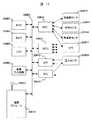
図1は本発明を用いたナビゲーション装置の全体構成を表す図である。本ナビゲーション装置は、姿勢検知手段10204により端末の姿勢を検知し、その検知量をもとにナビゲーション装置に設けられたスクリーンに垂直な視線ベクトルを算出する視線ベクトル算出手段10205と、表示対象量の検出手段10201及びその検出量を表示するための表示対象の提示用形状及び姿勢を求める提示用形状姿勢生成手段10202,提示用形状姿勢生成手段10202により生成された形状を10205で算出した視線ベクトルを用いて表示画像を表示する表示画像生成手段10203により構成される。 FIG. 1 is a diagram showing the overall configuration of a navigation apparatus using the present invention. This navigation device detects the terminal posture by posture detection means 10204, and based on the detected amount, calculates a line-of-sight vector perpendicular to the screen provided in the navigation device, and a display target amount. A display shape /
次に、図1の動きを、図2の本発明を用いたナビゲーション装置として用いる端末の外観図、図3の端末の姿勢検知手段の動作例、及び、図4の視線と表示対象量の関係を示す図を用いて説明する。表示対象量として本実施形態では磁北を示すベクトル(水平面に平行な磁北を示すベクトル、例えば10007のように方位磁石が指し示すベクトルである)を、端末の姿勢を様々に変化させた場合に、端末10005に取り付けられた表示用の画面(スクリーン)10003を覗き窓として方位磁石10007を可視化したような表示を行う例を説明する。 Next, the external view of the terminal used as the navigation device using the present invention of FIG. 2, the movement of FIG. 1 as an example of the operation of the attitude detection means of the terminal of FIG. It demonstrates using the figure which shows. In this embodiment, as a display target amount, when a vector indicating magnetic north (a vector indicating magnetic north parallel to a horizontal plane, for example, a vector indicated by a compass magnet as in 10007) is changed in various ways, the terminal An example will be described in which a display screen (screen) 10003 attached to 10005 is used as a viewing window to display such that the
本実施例における端末10005はアプリケーションプログラムが動作する携帯電話の外観を示しているが、PDAや表示画面が付いた腕時計など、形状を表示可能なスクリーン10003とアプリケーションプログラムが動作する端末であればどのような形態でもかまわない。 The
端末10005には姿勢を検知する姿勢検知手段10204が内蔵されている。この姿勢検知手段10204を使いスクリーンの姿勢を検知する。姿勢検知の一例を図3を用いて説明する。姿勢検知手段10204は、加速度センサと磁気センサを備えており、スクリーン10003に取り付けられているものとする。重力ベクトル10304は例えば3軸の加速度センサを用いて求める。重力加速度は静止状態であれば1Gであり、水平面
10303に垂直な成分となっている。スクリーン10003が傾斜することにより、各加速度センサからは、重力ベクトル10304と各々の加速度センサのなす角に比例した出力量が出力される。従って、各センサの成分量からスクリーン10003が受けている重力ベクトル10304を求める事が出来る。つまり、この重力ベクトルの成分は、スクリーン10003の傾きを示している。The
次に、スクリーン10003の向いている方向を決定するために地磁気ベクトルを利用する。地磁気ベクトル10302は、磁北ベクトル(10306)方向に向かって伏角
(10305)で水平面10303に向いている。地磁気ベクトル10302は3軸の磁気センサを用いて観測することが出来る。Next, the geomagnetic vector is used to determine the direction in which the
従って、先ほどの重力ベクトル10304と地磁気ベクトル10302を用いることにより、スクリーン10003の傾きと向いている絶対方位を検知する事が出来るので、スクリーン10003の絶対姿勢(傾きと方位)を検知することが出来る。スクリーン
10003の姿勢が検知できればこのスクリーンに垂直な視線ベクトル10002を求める事ができる。この演算はスクリーンに垂直な視線ベクトル算出手段10205を用いて行う。Therefore, by using the
次に、表示対象量の検出手段10201について説明する。本実施例では表示対象量として磁北ベクトルを例に取っているため、表示対象量の検出手段10201では磁気センサの出力を用いる。この磁気センサの出力はスクリーン10003の姿勢を検知した磁気センサの出力をそのまま利用する事ができる。図3で磁北ベクトル10306は、水平面10303に地磁気ベクトル10302を投影することにより求める事が出来る。この投影計算は表示対象の提示用形状とその姿勢を求める提示用形状姿勢生成手段10202で行う。ここで言う提示用形状とは、磁北ベクトルの指し示す方向を分かり易く表示する形状の事であり、図2では三角錐10008をその形状としている。また提示用形状の姿勢とは磁北ベクトルの方向であり、上記投影手法により求める事ができる。無論、提示用形状として三角錐以外の例えば矢印や人の指し示す指などを用いてもかまわない。これらの提示用形状を地磁気ベクトル10302と同じ方向にスクリーン上で座標変換する。 Next, the display target
視線ベクトル10002と表示対象量10008の姿勢をもとにスクリーン10003に表示させる手法については、図4を用いて説明する。表示対象量10008などを配置する際のワールド座標系10401と、表示対象量10008などを表示する際のスクリーン座標系10004がある。視点位置は、スクリーン座標系10004でスクリーンに垂直で原点を通る視線ベクトル10002上にあり、注視点はワールド座標系10401における表示対象量10008の位置とする。従って、表示対象量10008の位置をスクリーン座標系10004に対する視点位置からの透視変換する事により、表示対象量
10008のスクリーン10003における提示用形状が求まり、スクリーン10003の姿勢を変化させることにより、表示対象量10008の提示用形状の表示が変化する。A method of displaying on the
図5にその表示の一例と視点の位置を示す。視線10506はスクリーン10003に対して垂直方向が東を向いた状態である。この場合、表示対象量10008は左を指しているように表示され、北がスクリーン10003に対して左側である事を示す。視線
10505は、スクリーン10003を垂直に立て、ほぼ北北東の方向を向けた状態である。この場合、表示対象量10008は僅かに左側を向いており、北がスクリーン10003に対して僅かに左の方向であることを示している。視線10504は、スクリーン10003を地面に並行(真上から見る)にして覗いている状態である。この場合は真上から見た時の北の方向表示される。このように、様々な姿勢でも表示対象量10008(地磁気ベクトル10302)を直接可視化することが出来るので、直感的に表示対象量10008の指し示す方向を理解する事が出来る。FIG. 5 shows an example of the display and the position of the viewpoint. The line of
なお、本実施形態では表示対象量10008として地磁気ベクトル10302を描画する例を説明したが、表示対象量10008として水平面10303の傾きを表す事も可能であるし、地磁気ベクトル10302を表す事も可能である。その他、その位置における場の状態を表現する手段として本実施形態は適用できる。 In the present embodiment, an example in which the
次に、地理情報データベース17001と端末の位置検知手段17003を用いて、現在位置を基準として地理情報及び表示対象量10008を表示する方法について説明する。図1の端末の位置検知手段17003は、例えばGPSや無線LANの基地局情報,携帯電話の基地局情報,地面や壁・物などに取り付けられたRFIDの情報などを用いて位置を検知する。ここで検知する位置情報は、経度・緯度・高さで表す地理座標の値やX,Y,Zで表す3次元直交座標系でもかまわない。高さに関しては、楕円体高・標高・フロアーの階数などの値でもかまわない。高さの観測には位置検出手段と併用して高度計などを利用してもかまわない。図1に示す構成だけでは表示対象量10008の場の状態だけを検知していたが、位置検知手段17003で位置情報を検知することにより、端末が地理上の何処の位置に存在するかが判るようになる。 Next, a method of displaying the geographic information and the
地理情報データベース17001には、道路データや建物データ、店舗の位置や営業時間など地理情報に関する様々なデータが格納されている。このデータを可視化出来るように形状データに変換するのが描画用地理データ生成手段17002である。位置検知手段17003の情報をもとに描画用地理データ生成手段17002で周囲の地理情報を形状データに変換しで描画すると、図6に示すように端末の位置10703を中心にスクリーン10003の上端を北にして周囲の地理情報10702を描画することが出来る。また、図2で説明した手法により、表示対象量(この例では磁北ベクトル)を3次元的に可視化した形状10701を重ねて表示することが出来る。この磁北ベクトルを示す形状
10701は、スクリーン10003の傾斜に応じて覗き窓から見るように可視化した画像であり、端末の位置10703の情報と磁北ベクトル10701の状況を3次元的に可視化することにより直感的に端末の位置と磁北ベクトルの状況を理解出来る特徴がある。The
また、地理情報10702の画面に対する表示方向は固定(北が上)であったが、視線ベクトル算出手段10205によりスクリーン10003に垂直な視線方向を検知することにより、スクリーン10003に垂直な視線方向が向いている方位が上になるように地図を端末の位置10703を中心に回転して表示する事も可能である。この場合、自分の向いている方向を上とした地理情報を描画することが出来るために更に直感的に理解出来る地理情報を提示する事が可能になる。 The display direction of the
図7(a)は、図13における水平面10303と同じ位置に地理情報の画像を配置して描画した例である。水平面の状態は視線ベクトル算出手段10205で視線ベクトル
10002を演算する際に算出されるスクリーン10003に対する水平面の位置関係を利用して検知する。この水平面に描画用地理データ生成手段17002で生成した描画用地理データを重ね合わせることにより、スクリーン10003から覗いた時に見える地理情報(実世界と等価)を画面上に生成することが出来る。図7(a)はスクリーン10003を垂直にして覗いた状態を現す画面である。地理情報10801が遠近法で描かれて奥行きとして知覚することができる。図7(b)は図7(a)のスクリーン10003を右方向に回転した例である。回転に応じて水平面の位置も変化し、現実世界の水平面と平行になるように地理情報10801は描かれる。図7(c)はさらにスクリーン10003を回転して真横にした状態である。この状態でも地理情報10801は現実世界の水平面と同じ位置関係に描画される。FIG. 7A is an example in which an image of geographic information is drawn at the same position as the
また、視点方向を回転した場合(例えば、北から西に見る方角を買えた場合)には水平面も11003の回転軸で回転するので方角を変えても現実世界との対応関係は崩れない。さらに、スクリーンを地面と平行にして地面方向を覗くような動作を行った場合であっても水平面は追従するので真上から覗いた映像、例えば図6の描画画像10702のように真上から覗いた地理情報の映像を生成することが出来る。従って、スクリーン10003をいかなる方向に回転しても現実世界と対応が取れた地理情報を提供できるために直感的に理解し易い地理情報の提供が可能になる。 In addition, when the viewpoint direction is rotated (for example, when the direction seen from the north to the west can be bought), the horizontal plane also rotates with the rotation axis of 11003, so the correspondence with the real world does not collapse even if the direction is changed. Further, even when an operation is performed in which the screen is parallel to the ground and the direction of the ground is viewed, the horizontal plane follows, so that an image viewed from directly above, for example, the
また、姿勢検知手段によって、スクリーンに垂直なベクトルと重力ベクトルとが成す角が、ある一定角度以下(例えば10度以下)であることを検出した場合に、図6の様な2次元的な地図を表示し、そうでない場合には図7のような3次元的な地図を表示するということも可能である。この場合、図6のような地図を描画するためには、端末の位置検出手段において視点の高さを実際よりも高くし(例えば高度100mなど)、スクリーンに垂直な視線ベクトルの算出手段において、視線ベクトルを重力ベクトルに一致するとすればよい。 Further, when the posture detection means detects that the angle formed by the vector perpendicular to the screen and the gravity vector is less than a certain angle (for example, 10 degrees or less), a two-dimensional map as shown in FIG. It is also possible to display a three-dimensional map as shown in FIG. In this case, in order to draw a map as shown in FIG. 6, the height of the viewpoint is made higher than the actual position in the terminal position detection means (for example, altitude of 100 m), and the gaze vector calculation means perpendicular to the screen is The line-of-sight vector may be matched with the gravity vector.
情報提供手段として画像情報以外に音声を併用したり、あるいは単独で音声を利用して提示するために、発話文生成手段11301,発話音声生成手段11302を用いる。発話文生成手段11301は、提示用形状姿勢生成手段10202及び視線ベクトル算出手段10205より導かれるスクリーンと表示対象量の関係(図6における表示対象量を3次元的に可視化した形状10701)を発話文に変換する。例えば、スクリーンが図6のような姿勢で表示対象量が10701のように向いている場合には「画面の左上の奥行き方向が北を指しています」などと発話文を生成する。作られた発話文は発話音声生成手段11302を用いて音声信号に変換され、スピーカやイヤフォンを介して音として出力される。 In order to use the voice in addition to the image information as the information providing means, or to present it using the voice alone, the utterance sentence generation means 11301 and the utterance voice generation means 11302 are used. The utterance
また、表示対象量ではなくスクリーン10003の姿勢に応じて、そこに表示されている地理情報を地理情報データベース17001と視線ベクトルの関係により、発話文生成手段11301で発話文を生成することも可能である。例えば、図6に表示されているような画像が表示された場合、「右にあるビルは○△ビルです。左のビルは□×ビルです。」のような発話文が11301で生成され11302を用いて音声として出力される。なお、前記実施例では、スクリーンに垂直な視線ベクトルを基準にしたが、端末の特定の方向を指すベクトル、例えば携帯電話であればアンテナの指し示す方向を基準にして音声を発話させてもかまわない。この場合、アンテナの指し示す方向のビルの名前や山の名前などを画面を見ないで音声だけで案内することが可能になる。 Further, according to the posture of the
これまで姿勢検知手段10204及び表示対象の検出手段10201は端末に内蔵する事を前提に説明したが、外部にアタッチメント形式で取り付けられるようにしてもかまわない。この場合、スクリーンの姿勢とアタッチメントの姿勢や取り付け位置関係を定義することによって同様の構成で実現可能である。 Up to this point, the posture detection means 10204 and the display target detection means 10201 have been described on the assumption that they are built in the terminal, but they may be attached to the outside in the form of attachments. In this case, the same configuration can be realized by defining the orientation of the screen, the orientation of the attachment, and the attachment positional relationship.
次に、表示対象(目標対象物)が端末自体では検出できず通信回線を利用して表示目標対象の情報を取得して表示する実施形態を図8を用いて説明する。この実施例の変形では、目標対象物の位置姿勢検知手段11404,通信手段11402,11403,目標対象物の位置姿勢検知手段11404は検出手段10201と同様に目標物の位置や姿勢・状態を検知するセンサである。このセンサを用いて目標物の位置情報(高さも含む)や姿勢などを検知した情報を、通信手段11402,11403を介して目標対象物の形状姿勢生成手段11401へ送る。目標対象物の形状姿勢生成手段11401では、目標対象物の位置姿勢検知手段11404で検知した量を図形表示するための変換を行い、端末
(スクリーン10003)の姿勢を考慮して10203の表示画像の生成方法で描画される。Next, an embodiment in which the display target (target target) cannot be detected by the terminal itself and information about the display target is acquired and displayed using a communication line will be described with reference to FIG. In a modification of this embodiment, the target object position and orientation detection means 11404, the communication means 11402 and 11403, and the target object position and orientation detection means 11404 detect the position, posture and state of the target object in the same manner as the detection means 10201. It is a sensor. Information on the position information (including height) and orientation of the target using this sensor is sent to the shape / posture generation means 11401 of the target object via the communication means 11402 and 11403. The target object shape /
例えば目標対象物として路線バスを採用した場合、目標対象物の位置姿勢検知手段
11404ではバスの現在位置を検知する。バスの現在位置は例えばGPSなどを用いて検出可能である。この現在位置情報を通信手段11403,11402を介して端末
10005へ送信する。端末10005の位置は端末の位置検知手段17003で検知し、スクリーンの姿勢は10205で検知できるので、端末のスクリーン10003をバスが走行している方向に向ければ、図9に示すようにバスの現在位置11501が3次元的に把握できる。11502はバスのID情報などをもとに行き先を表示している。スクリーン10003の姿勢を検知しているので端末をどのような姿勢にしても、そのスクリーンの視界に入っていればバスの位置と方向を把握できる。図9では目標対象物としてバスを表示したが、目標対象物として待ち合わせをしている人を描画する場合でも同様の手法で実現できる。これにより待ち合わせの人が今どちらの方向に居て、どの程度離れているかを直感的に把握できる。For example, when a route bus is adopted as the target object, the target object position / orientation detection means 11404 detects the current position of the bus. The current position of the bus can be detected using, for example, GPS. This current position information is transmitted to the
実施例1では、ナビゲーション端末の利用者が目にしている現実世界をCGにより生成して経路の案内を行っていた。本実施例では、ナビゲーション端末の利用者が目にしている現実世界を、端末に付属するカメラにより撮影し、それと経路案内のCGを重ね合わせて経路誘導を行う。 In Example 1, the real world which the user of the navigation terminal sees was produced | generated by CG, and the route guidance was performed. In this embodiment, the real world that the user of the navigation terminal sees is photographed by a camera attached to the terminal, and route guidance is performed by superimposing it on the route guidance CG.
図10はカメラ付きの携帯端末の例として携帯電話を示した図である。携帯電話20105にはカメラ20009が内蔵または接続されており、撮影された画像はスクリーン10003に表示される。カメラの撮影する方向のベクトル(視線ベクトル)20010とスクリーンに垂直なベクトル20011の関係は予め判っているものとする。携帯電話20105には姿勢を検知する姿勢検知手段10204が内蔵されている。この姿勢検知手段10204を使いスクリーンの姿勢を検知する。図10では、カメラがスクリーンの上部に取り付けられているものとしているが、カメラの撮影方向はスクリーンを覗き込む端末利用者の視線と同じ方向を向いている。 FIG. 10 is a diagram showing a mobile phone as an example of a mobile terminal with a camera. A
カメラの取り付け方の別な例として、カメラの向きを変更できるものが考えられる。そのような構成例を図11に示す。図11は、カメラが回転可能な取り付けをされている例である。この図では、カメラ20009は、端末の折りたたみ蝶番部分に取り付けられており、折りたたみ部を軸として回転角変更できるようになっている。ここでカメラの回転角20014は、図11におけるスクリーンに垂直なベクトル20011を基準としてみたカメラの視線ベクトル20012の回転角θであると定義する。ここで、カメラの視線ベクトルとはカメラのレンズの光軸方向に平行で、レンズの全面に向いたベクトルを意味する。本端末はこのθを計測することが可能となっており、端末利用者が手でカメラを回した場合においても、スクリーンとカメラの視線ベクトルの関係が計測できるようになっている。 Another example of how to attach the camera is one that can change the orientation of the camera. An example of such a configuration is shown in FIG. FIG. 11 shows an example in which the camera is attached so as to be rotatable. In this figure, the
次に図12を用いてナビゲーションシステムの動作について説明する。図12のシステムでは、実施例1の図1のシステムに加えて、カメラ視線ベクトル算出手段27004,カメラ画像入力手段27005,表示画像合成手段27006,カメラ回転角取得手段
27007,経路探索手段27008、を備えている。また図1の描画用地理データ生成手段17002に代わって、描画用地理・経路データ生成手段27009を備えている。Next, the operation of the navigation system will be described with reference to FIG. In the system of FIG. 12, in addition to the system of FIG. 1 of the first embodiment, camera line-of-sight vector calculation means 27004, camera image input means 27005, display image composition means 27006, camera rotation angle acquisition means 27007, route search means 27008, I have. Further, in place of the drawing geographic data generation means 17002 in FIG. 1, a drawing geographic / route data generation means 27209 is provided.
カメラ回転角取得手段27007は、携帯端末上のカメラの回転角を得て、その情報をカメラの視線ベクトル算出手段27004に伝える。ここでカメラの回転角とは、図11におけるベクトル20011を基準としてみたカメラの視線ベクトル20012の回転角θ20014である。図10のようにカメラと携帯端末の姿勢との関係が一定の場合には、カメラ回転角取得手段27007は回転角0度を出力し続けるものとする。カメラ視線ベクトル算出手段27004は、カメラの回転角の情報を受け取るとともに、カメラの画角及びレンズの歪みの情報を視線ベクトル算出手段27004内にデータベースとして保持しており、CGを投影する時に必要な画角,レンズの歪み等のカメラパラメータを表示画像生成手段10203に出力する。 The camera rotation angle acquisition means 27007 obtains the rotation angle of the camera on the portable terminal and transmits the information to the camera line-of-sight vector calculation means 27004. Here, the rotation angle of the camera is a rotation angle θ20014 of the line-of-
カメラ画像入力手段27005は、携帯端末に付属するカメラからの画像を連続して取得し、また、表示画像合成手段27006に連続的に(ストリーミングで)出力する。表示画像合成手段27006は、表示画像生成手段10203からナビゲーションのためのCG画像を受け取り、カメラ画像入力手段27005から受け取ったカメラからの入力画像にCGの画像を重ね合わせ処理して、携帯端末のスクリーン上に表示する。 The camera image input means 27005 continuously acquires images from the camera attached to the mobile terminal, and outputs them continuously (by streaming) to the display image composition means 27006. The display
経路探索手段27008には、歩行者が予め設定する出発地点,目的地,経由地,交通手段(バス,電車,飛行機,船等)の情報が保持されており、また、それらの情報をもとに、地理情報データベース17001にアクセスを行うことで歩行者の誘導経路の探索を行い、探索した結果は経路探索手段27008内に保持する。また経路探索手段27008は、描画用地理・経路データ生成手段27009の要求に応じて、予め探索してある案内経路を三次元座標のデータ列として出力する。 The route search means 27008 stores information on starting points, destinations, waypoints, and transportation means (buses, trains, airplanes, ships, etc.) preset by pedestrians. In addition, the pedestrian guidance route is searched by accessing the
描画用地理・経路データ生成手段27009は、地理情報データベース17001に格納されている道路データや建物データ,店舗の位置データなどの地理情報を可視化するとともに、経路探索手段27008が出力する3次元座標のデータ列をもとに案内経路を3次元的なCGとして表現する。またその際、カメラ視線ベクトル算出手段27004からカメラの画角やレンズの歪みなどカメラパラメータの情報を受け取り、そのパラメータ情報をもとにカメラ画像に一致するCG画像を生成する。また表示対象の提示用形状姿勢生成手段27010でも、カメラ視線ベクトル算出手段27004からカメラの画角やレンズの歪みなどカメラパラメータの情報を受け取り、そのパラメータ情報をもとに、カメラ画像に一致するような表示対象量のCG画像を生成する。 The drawing-use geography / route data generation means 27008 visualizes geographical information such as road data, building data, and store location data stored in the
図13は、本発明を用いたナビゲーションシステムによる経路案内の例を示すための地図である。地理情報データベース17001には、道路(車道)20412,20426や、歩道20405,20413,20424といった道路データの他、歩道橋20407,横断歩道20411,陸橋20418,線路20401,駅20402,ランドマークとなるような建物20414,20421等の施設情報や地形の三次元形状情報(緯度経度に沿って等間隔のメッシュに分割された領域の高度情報または路側の高度情報など)および交通標識の設置情報(設置位置と標識種別または表示内容)が格納されている。案内経路20423は経路探索手段27008より探索された歩行者の誘導経路を表している。また、視点20425,20494,20495はそれぞれ図14,図15,図16の視点位置と端末の方向(視線の方向)を表している。そして視点20425における視野は、見える範囲の左端20408,見える範囲の右端20417,視野の最も遠方の位置を示す円弧20420で表されている。 FIG. 13 is a map for showing an example of route guidance by the navigation system using the present invention. In the
図14は本実施例における経路誘導のための経路表示画面である。図13における視点20425で示された経路誘導が開始される地点において、歩行者は現在歩道に立っており、携帯電話20105を手に持っているものとする。携帯電話の表示装置には、カメラ画像入力手段27005から入力される携帯電話のカメラで撮影されている風景画像が映っており、歩行者が手を動かすとその動きに従って表示装置に写っている風景画像も動く。本実施例では画面の更新周期は100ミリ秒とする。図10に示すカメラ付き携帯電話20105を使うと、ディスプレイに対して反対方向を向いたカメラを使うことにより、ディスプレイ上に今利用者が見ている現実世界と同じ映像をディスプレイ上に写し出すことが出来る。 FIG. 14 is a route display screen for route guidance in this embodiment. It is assumed that the pedestrian is currently standing on the sidewalk and holding the
図14に示す経路表示画面では、本発明を用いたナビゲーションシステムの経路表示が行われており、携帯電話20105のメインディスプレイ20511には、歩道20107,車道20426の他、交通標識20102,陸橋20418等の施設情報や、山20104や土手20110,林20101といった携帯電話20105のカメラにより撮影された画像が表示され、表示画像合成手段27006により、写っているカメラからの映像の上部には日付及び時刻表示20301,目的地までの到達予想時間20501,経由ポイントまでの到達予想時間20502が合成されて表示されている。また表示画像合成手段
27006によりカメラにより撮影されている画像に重ねて、案内経路(誘導経路)
20423を表す矢印,視野に無い建物20414の輪郭を表す表示,交差点20508を示す表示,横断歩道20411を示す点線20512が描画される。また案内経路
20423についても、視野の範囲外となる部分、および地形の三次元形状情報に基づき視点位置から見て陰面となる範囲を通過する部分については点線で描画される。In the route display screen shown in FIG. 14, the route display of the navigation system using the present invention is performed. The
An arrow indicating 20423, a display indicating the outline of the
案内経路20423を表す矢印の描画においては、矢印の先端の間隔が一定の歩行距離を表していて、本実施例では1分とする。視野に入っている案内経路20423の一部は実線3本で表現されている。案内経路20423は、歩行者の位置に近い部分から遠方にいくにつれて、その3本の間隔を狭く表示して奥行きを表現している。これは表示画像生成手段10203における表示変換処理(透視変換処理)により行われる。交差点を示す表示20508は視野外にあるT字路の案内経路20423における誘導交差点の輪郭を線画で表している。また点線20512は視野外にある誘導交差点に設けられた横断歩道20411の存在を示していて、案内経路20423によりT字路で左折することが表されている。なお、案内経路20423上のどの交差点が誘導交差点となるかは、経路探索手段27008により案内経路が探索された時に決定される。図14で表示されている視野よりも、歩行者から見て携帯電話を左方向に向けた場合、ディスプレイに表示されているカメラの画像は携帯電話の向きの変化に連動して変化し、これと共にカメラ画像に重ねて描画される経路のCG画像も変化する。 In the drawing of the arrow representing the
図14に示した画面の誘導に従い、歩行者が更に遠方の地点まで経路上を前進した場合のナビゲーションシステムの表示を図15,図16に示す。図15は、図13の視点
20494の位置における視野で見える経路のCG画像を表示した画面であり、図16は視点20495の位置に居て、図15よりも歩行者から見て携帯を左方向に向けた視野で見える経路のCG画像を表示した画面である。図15においては、視点20425の視野では周囲の地形により隠されていて波線で描画されていた案内経路20423が実線で描画されている。視点20425の視野外にあった横断歩道20411や建物20414の点線表示は消え、カメラの映像だけになっている。FIG. 15 and FIG. 16 show the display of the navigation system when the pedestrian advances on the route to a farther point according to the guidance of the screen shown in FIG. FIG. 15 is a screen displaying a CG image of a route that can be seen in the visual field at the position of the
また図16においては、視点20495において周囲の地形により隠される歩道橋
20407の一部がCG画像により点線20803で補われている。同様にして、案内経路20423が周囲の地形により隠されている部分についても点線により描画されている。但し、木立や林などの植生20806によって隠れる部分については、地形の三次元形状情報からは案内経路が陰面に存在することが判定できないため、実線で描画されてしまう。さらに、誘導交差点ではない路地などとの交差点については、その存在を示す簡単な線画2080のみが描画される。そして、案内経路の目的地である駅20402については、その存在を強調するためにマーク20802を重ねて描画される。In FIG. 16, a part of the
図17は、本発明を用いたナビゲーションシステム(携帯電話)のハードウェア構成を示す図である。携帯電話20105は、システムバス20902で互いに接続された、リードオンリーメモリ(ROM)20901,ランダムアクセスメモリ(RAM)20903,中央演算処理回路(CPU)20904,画像入力回路20905,圧力センサ
20918がつながったアナログディジタル変換回路(A/D)20912とディジタルアナログ変換回路(D/A)20913、及び加速度センサ20914,方位センサ
20915,角速度センサ20916,グローバルポジショニングシステム信号受信器
(GPS)20917等のセンサが接続されたシリアルインタフェース(SCI1) 20910と外部の機器と通信するためのシリアルインタフェース(SCI2)20911,通信モジュール20919とこれに接続されたアンテナ20920から構成される。FIG. 17 is a diagram showing a hardware configuration of a navigation system (mobile phone) using the present invention. A
CPU20904はナビゲーションシステム全体の動作を司り、ROM20901にはナビゲーションシステムの動作に必要な基本的なプログラムが納められている。さらに追加で必要なプログラムは、通信モジュール20919を通じ、RAM20903に必要に応じてダウンロードする。またRAM20903には、実行時に必要な一時データも格納される。加速度センサ20914,方位センサ20915,角速度センサ20916,
GPS20917からの情報は、シリアルインタフェース20910を経由してCPU
20904で処理される。圧力センサ20918の情報は、アナログディジタル変換回路20912を経由してCPU20904で処理される。またディジタルアナログ変換回路20913から圧力センサ20918に出力されるアナログ信号により、圧力センサのオフセット値及び増幅率が決定される。これにより、少ない量子化数で広いレンジを高精度にサンプリングすることができる。The
Information from the
Processed at 20904. Information of the
加速度センサ20914によって、携帯端末静止時には、重力加速度を検出することにより、携帯端末の傾きに関する情報を得ることができる。この加速度センサは3軸のセンサであるとする。また、加速度センサ20914によって携帯電話の上下動の周波数を計測することで、この携帯電話を持っている人の歩行速度を概算することができる。方位センサ20915から得られる情報と加速度センサ20914から得られる情報を組み合わせることにより、端末のカメラが向いている方位の情報を得ることができる。角速度センサと方位センサの情報を組み合わせることにより、方位の乱れを補整することができる。GPS20917により、絶対的な緯度経度の情報を得ることができる。 The
以上、本実施例の説明では、実写画像と主として経路CG画像の重ね合わせについて説明した。しかしながら、実写画像の代わりに風景CG画像を用いることも可能である。その場合、実施例1に経路案内機能が付加されたことになり、フルCGでの経路案内も可能である。 In the above description of the present embodiment, the superposition of the actual image and the route CG image has been described. However, it is also possible to use a landscape CG image instead of the actual image. In that case, the route guidance function is added to the first embodiment, and the route guidance with full CG is also possible.
図18に、経路CG画像を風景CG画像に重ね合わせる場合のシステムの構成例を示す。風景CG生成処理22901は、GIS情報21001,位置検知処理21003,姿勢検知処理21004から情報を受け取り、実際にカメラから見える風景の3次元CGを生成する。3次元CGの視点位置および視線方向は、上記の説明と同様にして求められる。 FIG. 18 shows a configuration example of a system when a route CG image is superimposed on a landscape CG image. A landscape CG generation process 22901 receives information from the
また、セレクタ23001により、風景の映像を実写画像と3次元CGとの間で切り替えられるようにして、画像入力処理21006からの実写画像と風景CG生成処理22901からのCGとを切り替えて、画像重ね合わせ処理21008に画像データを渡す構成とする。風景画像として実写画像とCGとを容易に切り替えられるようにすることで、計算機やネットワーク負荷を減らしたい場合には実写画像を用い、また、夜間や雨,霧のときなど、実写画像がよく見えない場合にはCGを用いる、といった使い分けが可能となる。 In addition, the
本発明を、携帯端末に用いることにより、実写画像とCG画像を組み合わせた直感的に分かり易い案内表示を行うことにより、使い易い経路案内システムを実現することができる。 By using the present invention for a mobile terminal, an easy-to-understand guidance display combining a photographed image and a CG image is performed, whereby an easy-to-use route guidance system can be realized.
10201…表示対象量の検出手段、10202…提示用形状姿勢生成手段、10203…表示画像生成手段、10204…姿勢検知手段、10205…視線ベクトル算出手段、
11301…発話文生成手段、11302…発話音声生成手段、17001…地理情報データベース、17003…位置検知手段、27004…カメラ視線ベクトル算出手段、
27005…カメラ画像入力手段、27006…表示画像合成手段、27007…カメラ回転角取得手段、27008…経路探索手段、27009…描画用地理・経路データ生成手段。
10201: Display target amount detection means, 10202 ... Presentation shape / posture generation means, 10203 ... Display image generation means, 10204 ... Posture detection means, 10205 ... Gaze vector calculation means,
11301 ... utterance sentence generation means, 11302 ... utterance voice generation means, 17001 ... geographic information database, 17003 ... position detection means, 27004 ... camera gaze vector calculation means,
27005 ... Camera image input means, 27006 ... Display image composition means, 27007 ... Camera rotation angle acquisition means, 27008 ... Path search means, 270099 ... Geographic / route data generation means for drawing.
Claims (6)
Translated fromJapanese地形の三次元形状情報を格納した地理情報記憶手段と、
端末装置の姿勢を検出する姿勢検知手段と、
該姿勢検知手段により求められた姿勢情報に基づいて、端末に備わった前記表示手段に垂直方向のベクトル情報を求め、前記位置検出手段により求められる現在位置と該ベクトル情報により定められる視線の情報と前記地理情報記憶手段の三次元形状情報から該視点における三次元地形画像を作成する画像生成手段を備え、
端末の姿勢を変化させた場合には、その姿勢変化に追従して前記表示手段上の三次元地形画像を更新すること
を特徴とする端末装置。In the terminal device provided with the position detection means and the display means,
Geographic information storage means storing the three-dimensional shape information of the terrain,
Attitude detection means for detecting the attitude of the terminal device;
Based on the posture information obtained by the posture detection means, vertical vector information is obtained from the display means provided in the terminal, and the current position obtained by the position detection means and the line-of-sight information determined by the vector information, Image generating means for creating a three-dimensional terrain image at the viewpoint from the three-dimensional shape information of the geographic information storage means,
A terminal device that updates a three-dimensional terrain image on the display unit in accordance with the change in posture when the posture of the terminal is changed.
地形の三次元形状情報を格納した地理情報記憶手段と、
端末装置の姿勢を検出する姿勢検知手段と、
該姿勢検知手段により求められた姿勢情報に基づいて、端末に備わった前記表示手段に垂直方向のベクトル情報を求め、前記位置検出手段により求められる現在位置と該ベクトル情報により定められる視線の情報と前記地理情報記憶手段の三次元形状情報から該視点における三次元地形画像を作成する画像生成手段と、
前記カメラからの画像に前記三次元地形画像を重ね合わせる画像合成手段を備え、
端末装置の姿勢を変化させた場合には、その姿勢変化に追従して前記カメラからの画像に重ね合わせる三次元地形画像を更新すること
を特徴とする端末装置。In a terminal device comprising a camera for image input, position detection means, and display means,
Geographic information storage means storing the three-dimensional shape information of the terrain,
Attitude detection means for detecting the attitude of the terminal device;
Based on the posture information obtained by the posture detection means, vertical vector information is obtained from the display means provided in the terminal, and the current position obtained by the position detection means and the line-of-sight information determined by the vector information, Image generating means for creating a three-dimensional terrain image at the viewpoint from the three-dimensional shape information of the geographic information storage means;
Comprising image combining means for superimposing the three-dimensional terrain image on the image from the camera;
When the attitude of the terminal apparatus is changed, the terminal apparatus updates the three-dimensional terrain image to be superimposed on the image from the camera following the attitude change.
前記表示手段に垂直方向のベクトルに対するカメラの光軸方向の変更量を検出する手段を備え、
前記画像生成手段において三次元地形画像を作成する際には、前記視線の情報を前記検出した変化量で補正し、
前記カメラの取り付け方向または位置を変更した場合にでも、前記表示手段の表示における前記カメラからの画像と該画像に重ね合わせる三次元地形画像とが一致するようにしたことを特徴とする端末装置。The terminal device according to claim 2,
The display means comprises means for detecting the amount of change in the optical axis direction of the camera with respect to the vector in the vertical direction,
When creating a three-dimensional terrain image in the image generation means, correct the information of the line of sight with the detected change amount,
A terminal device characterized in that an image from the camera displayed on the display means coincides with a three-dimensional topographic image to be superimposed on the image even when the mounting direction or position of the camera is changed.
地形の三次元形状情報を格納した地理情報記憶手段と、
ナビゲーション装置の姿勢を検出する姿勢検知手段と、
該姿勢検知手段により求められた姿勢情報に基づいて、端末に備わった前記表示手段に垂直方向のベクトル情報を求め、前記位置検出手段により求められる現在位置と該ベクトル情報により定められる視線の情報と前記地理情報記憶手段の三次元形状情報から、該視点における前記経路探索手段により求められた誘導経路および誘導情報の三次元形状画像を作成する画像生成手段と、
前記カメラからの画像に前記誘導経路および誘導情報の三次元形状画像を重ね合わせる画像合成手段を備え、
ナビゲーション装置の姿勢または現在位置を変化させた場合には、その変化に追従して前記カメラからの画像に重ね合わせる三次元形状画像を更新すること
を特徴とするナビゲーション装置。In a navigation device comprising a camera for image input, position detection means, route search means and display means,
Geographic information storage means storing the three-dimensional shape information of the terrain,
Attitude detection means for detecting the attitude of the navigation device;
Based on the posture information obtained by the posture detection means, vertical vector information is obtained from the display means provided in the terminal, and the current position obtained by the position detection means and the line-of-sight information determined by the vector information, Image generation means for creating a three-dimensional shape image of the guidance route and guidance information obtained by the route search means at the viewpoint from the three-dimensional shape information of the geographic information storage means;
Comprising image combining means for superimposing the three-dimensional shape image of the guide route and guide information on the image from the camera;
A navigation device, wherein when a posture or a current position of a navigation device is changed, a three-dimensional shape image to be superimposed on an image from the camera is updated following the change.
前記表示手段に垂直方向のベクトルに対するカメラの光軸方向の変更量を検出する手段を備え、
前記画像生成手段において三次元形状画像を作成する際には、前記視線の情報を前記検出した変化量で補正し、
前記カメラの取り付け方向または位置を変更した場合にでも、前記表示手段の表示における前記カメラからの画像と該画像に重ね合わせる三次元形状画像とが一致するようにしたことを特徴とするナビゲーション装置。The navigation device according to claim 4,
The display means comprises means for detecting the amount of change in the optical axis direction of the camera with respect to the vector in the vertical direction,
When creating a three-dimensional shape image in the image generation means, correct the information of the line of sight with the detected change amount,
A navigation apparatus, wherein an image from the camera displayed on the display means and a three-dimensional shape image superimposed on the image coincide with each other even when the mounting direction or position of the camera is changed.
5. The navigation device according to claim 4, wherein when a building whose information is registered in the geographic information database exists within a range of image capturing by the camera, the building is highlighted.
Priority Applications (4)
| Application Number | Priority Date | Filing Date | Title |
|---|---|---|---|
| JP2004289513AJP2006105640A (en) | 2004-10-01 | 2004-10-01 | Navigation device |
| TW094126064ATWI269024B (en) | 2004-10-01 | 2005-08-01 | Navigation system |
| US11/206,821US7457705B2 (en) | 2004-10-01 | 2005-08-19 | Navigation apparatus for displaying three-d stored terrain information based on position and attitude |
| CN200510109943.9ACN1755326B (en) | 2004-10-01 | 2005-09-20 | navigation device |
Applications Claiming Priority (1)
| Application Number | Priority Date | Filing Date | Title |
|---|---|---|---|
| JP2004289513AJP2006105640A (en) | 2004-10-01 | 2004-10-01 | Navigation device |
Publications (1)
| Publication Number | Publication Date |
|---|---|
| JP2006105640Atrue JP2006105640A (en) | 2006-04-20 |
Family
ID=36126606
Family Applications (1)
| Application Number | Title | Priority Date | Filing Date |
|---|---|---|---|
| JP2004289513APendingJP2006105640A (en) | 2004-10-01 | 2004-10-01 | Navigation device |
Country Status (4)
| Country | Link |
|---|---|
| US (1) | US7457705B2 (en) |
| JP (1) | JP2006105640A (en) |
| CN (1) | CN1755326B (en) |
| TW (1) | TWI269024B (en) |
Cited By (35)
| Publication number | Priority date | Publication date | Assignee | Title |
|---|---|---|---|---|
| WO2006109527A1 (en)* | 2005-03-30 | 2006-10-19 | National University Corporation Kumamoto University | Navigation device and navigation method |
| JP2009036726A (en)* | 2007-08-03 | 2009-02-19 | Yahoo Japan Corp | Search route display method and search route display system |
| JP2009128356A (en)* | 2007-11-26 | 2009-06-11 | Korea Electronics Telecommun | Car navigation system and method |
| JP2009239621A (en)* | 2008-03-27 | 2009-10-15 | Acreeg Corp | Method and device of orientation representation on image, and photograph |
| JP2010136282A (en)* | 2008-12-08 | 2010-06-17 | Hitachi Kokusai Electric Inc | Data transmission system |
| US7756638B2 (en) | 2006-09-13 | 2010-07-13 | Casio Hitachi Mobile Communications Co., Ltd. | Mobile terminal device and program |
| JP2010531007A (en)* | 2007-05-25 | 2010-09-16 | グーグル インコーポレイテッド | Draw, view, and annotate panoramic images and their applications |
| JP2011135165A (en)* | 2009-12-22 | 2011-07-07 | Sony Corp | Imaging device, method of processing orientation information, and program |
| JP2011138258A (en)* | 2009-12-28 | 2011-07-14 | Rakuten Inc | View reproduction system |
| WO2011093031A1 (en) | 2010-02-01 | 2011-08-04 | 日本電気株式会社 | Portable terminal, action history depiction method, and action history depiction system |
| JP2011188340A (en)* | 2010-03-10 | 2011-09-22 | Nec Casio Mobile Communications Ltd | Imaging apparatus and program |
| CN102211638A (en)* | 2010-04-08 | 2011-10-12 | 笠基电子股份有限公司 | Vehicle meter device capable of displaying geographic information |
| JP2012100009A (en)* | 2010-11-01 | 2012-05-24 | Canon Inc | Imaging device and control method of the same |
| CN102549631A (en)* | 2009-09-30 | 2012-07-04 | 松下电器产业株式会社 | Vehicle-surroundings monitoring device |
| JP2012213064A (en)* | 2011-03-31 | 2012-11-01 | Kddi Corp | Terminal user leading guidance system for radio terminal |
| JP2012244509A (en)* | 2011-05-23 | 2012-12-10 | Alpine Electronics Inc | Vehicle-mounted system |
| WO2012169422A1 (en)* | 2011-06-10 | 2012-12-13 | オリンパス株式会社 | Attachment |
| JP2013048361A (en)* | 2011-08-29 | 2013-03-07 | Olympus Imaging Corp | Portable device |
| JP2013518275A (en)* | 2010-01-29 | 2013-05-20 | インテル・コーポレーション | Method for providing information on object not included in field of view of terminal device, terminal device, and computer-readable recording medium |
| JP2013124957A (en)* | 2011-12-15 | 2013-06-24 | Car Mate Mfg Co Ltd | Navigation system using portable information terminal |
| JP2013179544A (en)* | 2012-02-29 | 2013-09-09 | Casio Comput Co Ltd | Photographing device and photography control method and program |
| WO2013157136A1 (en)* | 2012-04-20 | 2013-10-24 | トヨタ自動車株式会社 | Information identification device |
| JP2013253978A (en)* | 2013-06-25 | 2013-12-19 | Kyocera Corp | Mobile telephone |
| JP2015064889A (en)* | 2008-12-22 | 2015-04-09 | インテリジェント スペイシャル テクノロジーズ,インク. | System and method for initiating action and providing feedback by pointing at object of interest |
| JPWO2013115204A1 (en)* | 2012-01-30 | 2015-05-11 | 日本電気株式会社 | Information processing system, information processing method, information processing apparatus and control method and control program thereof, communication terminal and control method and control program thereof |
| JP2015129696A (en)* | 2014-01-08 | 2015-07-16 | Kddi株式会社 | Route guidance system, method, program and data structure thereof |
| JP2015523624A (en)* | 2012-05-07 | 2015-08-13 | 本田技研工業株式会社 | A method for generating a virtual display surface from a video image of a landscape based on a road |
| US20150319571A1 (en)* | 2007-03-12 | 2015-11-05 | Qualcomm Incorporated | Network independent location services |
| JP2016151453A (en)* | 2015-02-17 | 2016-08-22 | 株式会社Screenホールディングス | Route guiding device and route guiding method |
| JP2017076411A (en)* | 2016-11-21 | 2017-04-20 | 日本無線株式会社 | Information distribution apparatus, information distribution system, and information distribution method |
| JP2020501288A (en)* | 2016-12-12 | 2020-01-16 | セイフガード イクウィップメント インコーポレイテッド | Energy detection warning device |
| WO2021019591A1 (en)* | 2019-07-26 | 2021-02-04 | マクセル株式会社 | Path display device |
| JP2022167560A (en)* | 2021-04-23 | 2022-11-04 | 東芝Itコントロールシステム株式会社 | Destination guidance system |
| WO2023127430A1 (en)* | 2021-12-28 | 2023-07-06 | ソニーグループ株式会社 | Information processing device, image processing method, and program |
| WO2024225082A1 (en)* | 2023-04-26 | 2024-10-31 | ソニーグループ株式会社 | Information processing method, information processing device, and program |
Families Citing this family (75)
| Publication number | Priority date | Publication date | Assignee | Title |
|---|---|---|---|---|
| JP2006105640A (en)* | 2004-10-01 | 2006-04-20 | Hitachi Ltd | Navigation device |
| US8301159B2 (en)* | 2004-12-31 | 2012-10-30 | Nokia Corporation | Displaying network objects in mobile devices based on geolocation |
| US7720436B2 (en)* | 2006-01-09 | 2010-05-18 | Nokia Corporation | Displaying network objects in mobile devices based on geolocation |
| CN101151508B (en)* | 2005-03-28 | 2012-01-04 | 旭化成电子材料元件株式会社 | Traveling direction measuring apparatus and traveling direction measuring method |
| US8423292B2 (en)* | 2008-08-19 | 2013-04-16 | Tomtom International B.V. | Navigation device with camera-info |
| DE602005016311D1 (en) | 2005-06-06 | 2009-10-08 | Tomtom Int Bv | NAVIGATION DEVICE WITH CAMERA INFO |
| US7557736B1 (en)* | 2005-08-31 | 2009-07-07 | Hrl Laboratories, Llc | Handheld virtual overlay system |
| JP5075331B2 (en)* | 2005-09-30 | 2012-11-21 | アイシン・エィ・ダブリュ株式会社 | Map database generation system |
| JP2007133489A (en)* | 2005-11-08 | 2007-05-31 | Sony Corp | Virtual space image display method and device, virtual space image display program and recording medium |
| KR100721560B1 (en)* | 2005-11-30 | 2007-05-23 | 한국전자통신연구원 | 3D vehicle information providing system and method therefor |
| EP1814017A1 (en)* | 2006-01-26 | 2007-08-01 | Lg Electronics Inc. | Portable device with improved user interface |
| US20070229538A1 (en)* | 2006-03-31 | 2007-10-04 | Research In Motion Limited | Methods and apparatus for dynamically labeling map objects in visually displayed maps of mobile communication devices |
| US9478133B2 (en) | 2006-03-31 | 2016-10-25 | Volkswagen Ag | Motor vehicle and navigation arrangement for a motor vehicle |
| US20070233371A1 (en)* | 2006-03-31 | 2007-10-04 | Arne Stoschek | Navigation system for a motor vehicle |
| US8700308B2 (en)* | 2006-03-31 | 2014-04-15 | Volkswagen Ag | Navigation system for a motor vehicle |
| US20070275735A1 (en)* | 2006-05-23 | 2007-11-29 | Texas Instruments, Inc. | Map information communicated via a wireless system |
| CN101097144B (en)* | 2006-06-30 | 2011-10-19 | 佛山市顺德区顺达电脑厂有限公司 | Navigation system having realistic display and method thereof |
| JP4816340B2 (en)* | 2006-08-31 | 2011-11-16 | ソニー株式会社 | Navigation device, position detection method, and position detection program |
| DE102006048182A1 (en)* | 2006-10-10 | 2008-04-17 | Navigon Ag | Navigation device and method for displaying a road map with isolines |
| US8171237B2 (en)* | 2006-10-31 | 2012-05-01 | Yahoo! Inc. | Automatic association of reference data with primary process data based on time and shared identifier |
| US20080221791A1 (en)* | 2007-03-08 | 2008-09-11 | Predrag Sukovic | Landmark identifier |
| JP2010534455A (en)* | 2007-03-24 | 2010-11-04 | 躍軍 閻 | Portable digital imaging system combining positioning navigation information and image information |
| US7990394B2 (en) | 2007-05-25 | 2011-08-02 | Google Inc. | Viewing and navigating within panoramic images, and applications thereof |
| US7843451B2 (en)* | 2007-05-25 | 2010-11-30 | Google Inc. | Efficient rendering of panoramic images, and applications thereof |
| US8515207B2 (en)* | 2007-05-25 | 2013-08-20 | Google Inc. | Annotations in panoramic images, and applications thereof |
| CN101339038B (en)* | 2007-07-02 | 2011-08-17 | 佛山市顺德区顺达电脑厂有限公司 | Real scene navigation apparatus |
| CN101109643B (en)* | 2007-08-22 | 2011-06-29 | 广东瑞图万方科技有限公司 | Navigation apparatus |
| JP5564946B2 (en)* | 2007-09-20 | 2014-08-06 | 日本電気株式会社 | Video providing system and video providing method |
| CN101482417B (en)* | 2008-01-08 | 2011-08-24 | 宏达国际电子股份有限公司 | Satellite navigation method and system |
| US8406531B2 (en) | 2008-05-15 | 2013-03-26 | Yahoo! Inc. | Data access based on content of image recorded by a mobile device |
| US8738291B2 (en)* | 2008-05-21 | 2014-05-27 | Navteq B.V. | Method and system for representing pedestrian crosswalks in a geographic database used by a navigation system |
| KR20090123227A (en)* | 2008-05-27 | 2009-12-02 | 삼성전자주식회사 | Search service provider, method and program |
| US9753948B2 (en)* | 2008-05-27 | 2017-09-05 | Match.Com, L.L.C. | Face search in personals |
| US8098894B2 (en) | 2008-06-20 | 2012-01-17 | Yahoo! Inc. | Mobile imaging device as navigator |
| DE102008049824B4 (en)* | 2008-10-01 | 2014-09-04 | Universität Kassel | Method for collision avoidance |
| CN101556154B (en)* | 2008-10-13 | 2013-08-21 | 美新半导体(无锡)有限公司 | Positioning and path map generation system and data acquisition analysis method thereof |
| US9600067B2 (en)* | 2008-10-27 | 2017-03-21 | Sri International | System and method for generating a mixed reality environment |
| CH700208B1 (en)* | 2009-01-07 | 2015-02-27 | Dr Marc Pierre Jaccard | Portable navigation device |
| US8159363B2 (en)* | 2009-02-16 | 2012-04-17 | Research In Motion Limited | Using gravity to direct a rotatable camera in a handheld electronic device |
| CN101852617B (en)* | 2009-03-30 | 2013-05-15 | 宏达国际电子股份有限公司 | Method and system for indicating direction of point of interest |
| JP5487677B2 (en)* | 2009-03-30 | 2014-05-07 | 富士通株式会社 | POSITION INFORMATION SERVICE DEVICE, METHOD, AND PROGRAM |
| US9477368B1 (en) | 2009-03-31 | 2016-10-25 | Google Inc. | System and method of indicating the distance or the surface of an image of a geographical object |
| JP5158006B2 (en)* | 2009-04-23 | 2013-03-06 | ソニー株式会社 | Information processing apparatus, information processing method, and program |
| JP5376223B2 (en)* | 2009-05-18 | 2013-12-25 | アイシン精機株式会社 | Driving assistance device |
| DE102009048492A1 (en)* | 2009-09-25 | 2011-03-31 | Valeo Schalter Und Sensoren Gmbh | A portable communication device, driver assistance system with a portable communication device, and method of assisting a driver in driving a vehicle |
| CN102054461A (en)* | 2009-11-09 | 2011-05-11 | 神基科技股份有限公司 | Method for adjusting image presenting direction of display of electronic device |
| TWI416073B (en) | 2009-11-16 | 2013-11-21 | Ind Tech Res Inst | Road image processing method and system of moving camera |
| CN101782642B (en)* | 2010-03-09 | 2011-12-21 | 山东大学 | Method and device for absolutely positioning measurement target by multi-sensor fusion |
| US20110248847A1 (en)* | 2010-04-08 | 2011-10-13 | Honeywell International Inc. | Mobile asset location in structure |
| US8937592B2 (en)* | 2010-05-20 | 2015-01-20 | Samsung Electronics Co., Ltd. | Rendition of 3D content on a handheld device |
| US20110302214A1 (en)* | 2010-06-03 | 2011-12-08 | General Motors Llc | Method for updating a database |
| US8730319B2 (en)* | 2010-07-09 | 2014-05-20 | Kabushiki Kaisha Toshiba | Display device, image data generating device, image data generating program, and display method |
| US8319772B2 (en)* | 2010-07-23 | 2012-11-27 | Microsoft Corporation | 3D layering of map metadata |
| CN101975578B (en)* | 2010-09-20 | 2012-10-17 | 北京腾瑞万里科技有限公司 | Navigation method and device |
| JP5598232B2 (en)* | 2010-10-04 | 2014-10-01 | ソニー株式会社 | Information processing apparatus, information processing system, and information processing method |
| TWI456165B (en)* | 2011-02-14 | 2014-10-11 | Mitac Int Corp | Vehicle navigating method and vehicle navigating system |
| TWI465696B (en)* | 2011-04-14 | 2014-12-21 | Mitac Int Corp | Method of planning customizable exercise routes for a user of a personal navigation device |
| US8816820B2 (en) | 2011-04-28 | 2014-08-26 | Honeywell International Inc. | System for synthetic vision |
| KR20120127830A (en) | 2011-05-16 | 2012-11-26 | 삼성전자주식회사 | User interface method for terminal of vehicle and apparatus tererof |
| US8788203B2 (en) | 2011-05-23 | 2014-07-22 | Microsoft Corporation | User-driven navigation in a map navigation tool |
| JP2014053794A (en)* | 2012-09-07 | 2014-03-20 | Nintendo Co Ltd | Information processing program, information processing apparatus, information processing system, and information processing method |
| CN102880686B (en)* | 2012-09-17 | 2016-03-02 | 曹欢欢 | A kind of interest point search method and device |
| CN103077624B (en)* | 2012-12-28 | 2015-07-29 | 天津爱迪尔软件开发有限公司 | A kind of instant navigation road condition system based on GPS and air navigation aid |
| CN104102678B (en)* | 2013-04-15 | 2018-06-05 | 腾讯科技(深圳)有限公司 | The implementation method and realization device of augmented reality |
| CN106969774A (en)* | 2013-04-28 | 2017-07-21 | 腾讯科技(深圳)有限公司 | Air navigation aid and device, terminal, server and system |
| CN103453901B (en)* | 2013-06-27 | 2016-09-28 | 展讯通信(上海)有限公司 | A kind of position guidance system and position guidance method |
| JP6358889B2 (en)* | 2013-09-26 | 2018-07-18 | 株式会社メガチップス | Pedestrian observation system, program, and traveling direction estimation method |
| CN104613973B (en)* | 2014-05-07 | 2018-11-06 | 腾讯科技(深圳)有限公司 | Picture generation, methods of exhibiting and device |
| US9676386B2 (en)* | 2015-06-03 | 2017-06-13 | Ford Global Technologies, Llc | System and method for controlling vehicle components based on camera-obtained image information |
| US10217283B2 (en) | 2015-12-17 | 2019-02-26 | Google Llc | Navigation through multidimensional images spaces |
| FR3048794B1 (en)* | 2016-03-09 | 2020-11-27 | Illusion 3D | SYSTEM AND METHOD FOR GUIDING IN THREE DIMENSIONS OF A USER |
| EP3482163B1 (en)* | 2016-07-07 | 2021-06-23 | Saab Ab | Displaying system and method for displaying a perspective view of the surrounding of an aircraft in an aircraft |
| US20180082119A1 (en)* | 2016-09-19 | 2018-03-22 | Project Ray Ltd. | System and method for remotely assisted user-orientation |
| CN109099933A (en)* | 2018-07-12 | 2018-12-28 | 百度在线网络技术(北京)有限公司 | The method and apparatus for generating information |
| WO2022010451A1 (en)* | 2020-07-06 | 2022-01-13 | Google Llc | Stable orientation cues for augmented reality (ar) |
Citations (3)
| Publication number | Priority date | Publication date | Assignee | Title |
|---|---|---|---|---|
| JPH09311625A (en)* | 1996-05-22 | 1997-12-02 | Sony Corp | Display device, map display device, display method, and map display method |
| JPH11108684A (en)* | 1997-08-05 | 1999-04-23 | Harness Syst Tech Res Ltd | Car navigation system |
| JP2003216982A (en)* | 2002-01-17 | 2003-07-31 | Sony Corp | Device and method for providing information, storage medium, and computer program |
Family Cites Families (28)
| Publication number | Priority date | Publication date | Assignee | Title |
|---|---|---|---|---|
| US2526682A (en)* | 1946-04-10 | 1950-10-24 | Henry C Mulberger | Flight indicating instrument |
| US3193822A (en)* | 1948-12-18 | 1965-07-06 | Goodyear Aerospace Corp | Pilotless aircraft navigational system |
| US3231887A (en)* | 1955-11-09 | 1966-01-25 | Goodyear Aerospace Corp | Aircraft guidance system including altitude controlling mechanism |
| GB2109514A (en)* | 1981-11-14 | 1983-06-02 | Invertron Simulated Syst | Guilded missile fire control simulators |
| US5422812A (en)* | 1985-05-30 | 1995-06-06 | Robert Bosch Gmbh | Enroute vehicle guidance system with heads up display |
| FR2593932B1 (en)* | 1986-02-04 | 1989-12-01 | Thomson Csf | LARGE FIELD VISUALIZATION DEVICE WITH HIGH OPTICAL EFFICIENCY |
| US4876651A (en)* | 1988-05-11 | 1989-10-24 | Honeywell Inc. | Digital map system |
| US5179638A (en)* | 1990-04-26 | 1993-01-12 | Honeywell Inc. | Method and apparatus for generating a texture mapped perspective view |
| EP0567660B2 (en)* | 1992-04-21 | 2000-09-06 | IBP Pietzsch GmbH | Device for the guiding of vehicles |
| US5412569A (en)* | 1994-03-29 | 1995-05-02 | General Electric Company | Augmented reality maintenance system with archive and comparison device |
| US5550758A (en)* | 1994-03-29 | 1996-08-27 | General Electric Company | Augmented reality maintenance system with flight planner |
| US5706195A (en)* | 1995-09-05 | 1998-01-06 | General Electric Company | Augmented reality maintenance system for multiple rovs |
| US5745387A (en)* | 1995-09-28 | 1998-04-28 | General Electric Company | Augmented reality maintenance system employing manipulator arm with archive and comparison device |
| US5751576A (en)* | 1995-12-18 | 1998-05-12 | Ag-Chem Equipment Co., Inc. | Animated map display method for computer-controlled agricultural product application equipment |
| US5721679A (en)* | 1995-12-18 | 1998-02-24 | Ag-Chem Equipment Co., Inc. | Heads-up display apparatus for computer-controlled agricultural product application equipment |
| US5838262A (en)* | 1996-12-19 | 1998-11-17 | Sikorsky Aircraft Corporation | Aircraft virtual image display system and method for providing a real-time perspective threat coverage display |
| US6229546B1 (en)* | 1997-09-09 | 2001-05-08 | Geosoftware, Inc. | Rapid terrain model generation with 3-D object features and user customization interface |
| US6477464B2 (en)* | 2000-03-09 | 2002-11-05 | Donnelly Corporation | Complete mirror-based global-positioning system (GPS) navigation solution |
| JP4094219B2 (en)* | 2000-09-19 | 2008-06-04 | アルパイン株式会社 | 3D map display method for in-vehicle navigation system |
| JP3773433B2 (en)* | 2000-10-11 | 2006-05-10 | シャープ株式会社 | Ambient monitoring device for moving objects |
| FR2826769B1 (en)* | 2001-06-29 | 2003-09-05 | Thales Sa | METHOD FOR DISPLAYING MAPPING INFORMATION ON AIRCRAFT SCREEN |
| JP3722364B2 (en)* | 2001-11-15 | 2005-11-30 | 国土交通省国土技術政策総合研究所長 | Pedestrian route guidance system and computer software program for causing computer system to execute processing related to pedestrian route guidance |
| DE10236221C1 (en)* | 2002-08-07 | 2003-11-20 | Siemens Ag | Navigation information display method for vehicle with onboard navigation aid, has virtual representation of pilot vehicle superimposed on image of vehicle surrounding area |
| US6822624B2 (en)* | 2002-09-10 | 2004-11-23 | Universal Avionics Systems Corporation | Display generation system |
| JP3766657B2 (en) | 2002-12-20 | 2006-04-12 | 株式会社日立製作所 | Map display device and navigation device |
| JP3972366B2 (en)* | 2003-09-26 | 2007-09-05 | マツダ株式会社 | Vehicle information providing device |
| US20050071082A1 (en)* | 2003-09-30 | 2005-03-31 | Mazda Motor Corporation | Route guidance apparatus, method and program |
| JP2006105640A (en)* | 2004-10-01 | 2006-04-20 | Hitachi Ltd | Navigation device |
- 2004
- 2004-10-01JPJP2004289513Apatent/JP2006105640A/enactivePending
- 2005
- 2005-08-01TWTW094126064Apatent/TWI269024B/ennot_activeIP Right Cessation
- 2005-08-19USUS11/206,821patent/US7457705B2/ennot_activeExpired - Fee Related
- 2005-09-20CNCN200510109943.9Apatent/CN1755326B/ennot_activeExpired - Fee Related
Patent Citations (3)
| Publication number | Priority date | Publication date | Assignee | Title |
|---|---|---|---|---|
| JPH09311625A (en)* | 1996-05-22 | 1997-12-02 | Sony Corp | Display device, map display device, display method, and map display method |
| JPH11108684A (en)* | 1997-08-05 | 1999-04-23 | Harness Syst Tech Res Ltd | Car navigation system |
| JP2003216982A (en)* | 2002-01-17 | 2003-07-31 | Sony Corp | Device and method for providing information, storage medium, and computer program |
Cited By (50)
| Publication number | Priority date | Publication date | Assignee | Title |
|---|---|---|---|---|
| WO2006109527A1 (en)* | 2005-03-30 | 2006-10-19 | National University Corporation Kumamoto University | Navigation device and navigation method |
| US7756638B2 (en) | 2006-09-13 | 2010-07-13 | Casio Hitachi Mobile Communications Co., Ltd. | Mobile terminal device and program |
| US10841729B2 (en)* | 2007-03-12 | 2020-11-17 | Qualcomm Incorporated | Network independent location services |
| US11678134B2 (en) | 2007-03-12 | 2023-06-13 | Qualcomm Incorporated | Network independent location services |
| US20150319571A1 (en)* | 2007-03-12 | 2015-11-05 | Qualcomm Incorporated | Network independent location services |
| US20210092552A1 (en)* | 2007-03-12 | 2021-03-25 | Qualcomm Incorporated | Network independent location services |
| JP2010531007A (en)* | 2007-05-25 | 2010-09-16 | グーグル インコーポレイテッド | Draw, view, and annotate panoramic images and their applications |
| JP2009036726A (en)* | 2007-08-03 | 2009-02-19 | Yahoo Japan Corp | Search route display method and search route display system |
| JP2009128356A (en)* | 2007-11-26 | 2009-06-11 | Korea Electronics Telecommun | Car navigation system and method |
| JP2009239621A (en)* | 2008-03-27 | 2009-10-15 | Acreeg Corp | Method and device of orientation representation on image, and photograph |
| JP2010136282A (en)* | 2008-12-08 | 2010-06-17 | Hitachi Kokusai Electric Inc | Data transmission system |
| JP2015064889A (en)* | 2008-12-22 | 2015-04-09 | インテリジェント スペイシャル テクノロジーズ,インク. | System and method for initiating action and providing feedback by pointing at object of interest |
| CN102549631B (en)* | 2009-09-30 | 2014-11-12 | 松下电器产业株式会社 | Surveillance device around the vehicle |
| CN102549631A (en)* | 2009-09-30 | 2012-07-04 | 松下电器产业株式会社 | Vehicle-surroundings monitoring device |
| US9280824B2 (en) | 2009-09-30 | 2016-03-08 | Panasonic Intellectual Property Management Co., Ltd. | Vehicle-surroundings monitoring device |
| US9106835B2 (en) | 2009-12-22 | 2015-08-11 | Sony Corporation | Imaging device, azimuth information processing method and program |
| JP2011135165A (en)* | 2009-12-22 | 2011-07-07 | Sony Corp | Imaging device, method of processing orientation information, and program |
| JP2011138258A (en)* | 2009-12-28 | 2011-07-14 | Rakuten Inc | View reproduction system |
| JP2013518275A (en)* | 2010-01-29 | 2013-05-20 | インテル・コーポレーション | Method for providing information on object not included in field of view of terminal device, terminal device, and computer-readable recording medium |
| WO2011093031A1 (en) | 2010-02-01 | 2011-08-04 | 日本電気株式会社 | Portable terminal, action history depiction method, and action history depiction system |
| JP2011188340A (en)* | 2010-03-10 | 2011-09-22 | Nec Casio Mobile Communications Ltd | Imaging apparatus and program |
| CN102211638A (en)* | 2010-04-08 | 2011-10-12 | 笠基电子股份有限公司 | Vehicle meter device capable of displaying geographic information |
| JP2012100009A (en)* | 2010-11-01 | 2012-05-24 | Canon Inc | Imaging device and control method of the same |
| JP2012213064A (en)* | 2011-03-31 | 2012-11-01 | Kddi Corp | Terminal user leading guidance system for radio terminal |
| JP2012244509A (en)* | 2011-05-23 | 2012-12-10 | Alpine Electronics Inc | Vehicle-mounted system |
| WO2012169422A1 (en)* | 2011-06-10 | 2012-12-13 | オリンパス株式会社 | Attachment |
| JP2013048361A (en)* | 2011-08-29 | 2013-03-07 | Olympus Imaging Corp | Portable device |
| JP2013124957A (en)* | 2011-12-15 | 2013-06-24 | Car Mate Mfg Co Ltd | Navigation system using portable information terminal |
| JPWO2013115204A1 (en)* | 2012-01-30 | 2015-05-11 | 日本電気株式会社 | Information processing system, information processing method, information processing apparatus and control method and control program thereof, communication terminal and control method and control program thereof |
| JP2013179544A (en)* | 2012-02-29 | 2013-09-09 | Casio Comput Co Ltd | Photographing device and photography control method and program |
| JPWO2013157136A1 (en)* | 2012-04-20 | 2015-12-21 | トヨタ自動車株式会社 | Information identification device |
| WO2013157136A1 (en)* | 2012-04-20 | 2013-10-24 | トヨタ自動車株式会社 | Information identification device |
| JP2015523624A (en)* | 2012-05-07 | 2015-08-13 | 本田技研工業株式会社 | A method for generating a virtual display surface from a video image of a landscape based on a road |
| JP2013253978A (en)* | 2013-06-25 | 2013-12-19 | Kyocera Corp | Mobile telephone |
| JP2015129696A (en)* | 2014-01-08 | 2015-07-16 | Kddi株式会社 | Route guidance system, method, program and data structure thereof |
| JP2016151453A (en)* | 2015-02-17 | 2016-08-22 | 株式会社Screenホールディングス | Route guiding device and route guiding method |
| JP2017076411A (en)* | 2016-11-21 | 2017-04-20 | 日本無線株式会社 | Information distribution apparatus, information distribution system, and information distribution method |
| JP2020501288A (en)* | 2016-12-12 | 2020-01-16 | セイフガード イクウィップメント インコーポレイテッド | Energy detection warning device |
| US12241917B2 (en) | 2016-12-12 | 2025-03-04 | Safeguard Equipment, Inc. | Energy detection warning device |
| JP7134994B2 (en) | 2016-12-12 | 2022-09-12 | セイフガード イクウィップメント インコーポレイテッド | Energy detection warning device |
| US12241918B2 (en) | 2016-12-12 | 2025-03-04 | Safeguard Equipment, Inc. | Energy detection warning device |
| US11579174B2 (en) | 2016-12-12 | 2023-02-14 | Safeguard Equipment, Inc. | Energy detection warning device |
| WO2021019591A1 (en)* | 2019-07-26 | 2021-02-04 | マクセル株式会社 | Path display device |
| JP2023075236A (en)* | 2019-07-26 | 2023-05-30 | マクセル株式会社 | Locus display device |
| JP7244649B2 (en) | 2019-07-26 | 2023-03-22 | マクセル株式会社 | Trajectory display device |
| JPWO2021019591A1 (en)* | 2019-07-26 | 2021-02-04 | ||
| JP7575337B2 (en) | 2021-04-23 | 2024-10-29 | 東芝Itコントロールシステム株式会社 | Destination Guidance System |
| JP2022167560A (en)* | 2021-04-23 | 2022-11-04 | 東芝Itコントロールシステム株式会社 | Destination guidance system |
| WO2023127430A1 (en)* | 2021-12-28 | 2023-07-06 | ソニーグループ株式会社 | Information processing device, image processing method, and program |
| WO2024225082A1 (en)* | 2023-04-26 | 2024-10-31 | ソニーグループ株式会社 | Information processing method, information processing device, and program |
Also Published As
| Publication number | Publication date |
|---|---|
| TW200622196A (en) | 2006-07-01 |
| US20060074549A1 (en) | 2006-04-06 |
| CN1755326B (en) | 2010-09-15 |
| CN1755326A (en) | 2006-04-05 |
| TWI269024B (en) | 2006-12-21 |
| US7457705B2 (en) | 2008-11-25 |
Similar Documents
| Publication | Publication Date | Title |
|---|---|---|
| CN1755326B (en) | navigation device | |
| US11692842B2 (en) | Augmented reality maps | |
| KR101285360B1 (en) | Point of interest displaying apparatus and method for using augmented reality | |
| US8036678B2 (en) | Real-time geographic information system and method | |
| US20090063047A1 (en) | Navigational information display system, navigational information display method, and computer-readable recording medium | |
| JP2009020089A (en) | NAVIGATION DEVICE, NAVIGATION METHOD, AND NAVIGATION PROGRAM | |
| JP2007133489A5 (en) | ||
| JP2009236844A (en) | Navigation device, navigation method, and navigation program | |
| JP2009236843A (en) | Navigation device, navigation method, and navigation program | |
| JP4892741B2 (en) | Navigation device and navigation method | |
| JP2022034099A (en) | Navigation device, navigation system, navigation method, and navigation program | |
| KR101659089B1 (en) | Augmented reality apparatus using position information | |
| JP2009036726A (en) | Search route display method and search route display system | |
| JP5527005B2 (en) | POSITION ESTIMATION DEVICE, POSITION ESTIMATION METHOD, AND POSITION ESTIMATION PROGRAM | |
| KR101215515B1 (en) | Image display apparatus based on recognizing selected location cordinates | |
| JP2014066595A (en) | Navigation apparatus | |
| WO2021019591A1 (en) | Path display device | |
| US12299213B2 (en) | Activating a handheld device with universal pointing and interacting device | |
| US20250285442A1 (en) | Providing Information of Objects in the Surroundings by a Handheld Device Using a Universal Pointing and Interacting Device | |
| JP2011149957A (en) | Image display device, image display method, and program | |
| JP3414728B2 (en) | Landscape display device | |
| JP2024140312A (en) | Virtual guidance display device and virtual guidance display method | |
| JP2011022152A (en) | Navigation device | |
| JP2002162240A (en) | Landscape display device | |
| JPH11148838A (en) | Portable guide device |
Legal Events
| Date | Code | Title | Description |
|---|---|---|---|
| RD04 | Notification of resignation of power of attorney | Free format text:JAPANESE INTERMEDIATE CODE: A7424 Effective date:20060425 | |
| A621 | Written request for application examination | Free format text:JAPANESE INTERMEDIATE CODE: A621 Effective date:20070604 | |
| A977 | Report on retrieval | Free format text:JAPANESE INTERMEDIATE CODE: A971007 Effective date:20091125 | |
| A131 | Notification of reasons for refusal | Free format text:JAPANESE INTERMEDIATE CODE: A131 Effective date:20091201 | |
| A521 | Request for written amendment filed | Free format text:JAPANESE INTERMEDIATE CODE: A523 Effective date:20100128 | |
| A02 | Decision of refusal | Free format text:JAPANESE INTERMEDIATE CODE: A02 Effective date:20100706 |