JP2006105598A - Acceleration / Angular velocity sensor unit - Google Patents
Acceleration / Angular velocity sensor unitDownload PDFInfo
- Publication number
- JP2006105598A JP2006105598AJP2004288361AJP2004288361AJP2006105598AJP 2006105598 AJP2006105598 AJP 2006105598AJP 2004288361 AJP2004288361 AJP 2004288361AJP 2004288361 AJP2004288361 AJP 2004288361AJP 2006105598 AJP2006105598 AJP 2006105598A
- Authority
- JP
- Japan
- Prior art keywords
- sensor
- axis
- angular velocity
- acceleration
- substrate
- Prior art date
- Legal status (The legal status is an assumption and is not a legal conclusion. Google has not performed a legal analysis and makes no representation as to the accuracy of the status listed.)
- Pending
Links
Images


Classifications
- G—PHYSICS
- G01—MEASURING; TESTING
- G01C—MEASURING DISTANCES, LEVELS OR BEARINGS; SURVEYING; NAVIGATION; GYROSCOPIC INSTRUMENTS; PHOTOGRAMMETRY OR VIDEOGRAMMETRY
- G01C21/00—Navigation; Navigational instruments not provided for in groups G01C1/00 - G01C19/00
- G01C21/10—Navigation; Navigational instruments not provided for in groups G01C1/00 - G01C19/00 by using measurements of speed or acceleration
- B—PERFORMING OPERATIONS; TRANSPORTING
- B60—VEHICLES IN GENERAL
- B60T—VEHICLE BRAKE CONTROL SYSTEMS OR PARTS THEREOF; BRAKE CONTROL SYSTEMS OR PARTS THEREOF, IN GENERAL; ARRANGEMENT OF BRAKING ELEMENTS ON VEHICLES IN GENERAL; PORTABLE DEVICES FOR PREVENTING UNWANTED MOVEMENT OF VEHICLES; VEHICLE MODIFICATIONS TO FACILITATE COOLING OF BRAKES
- B60T8/00—Arrangements for adjusting wheel-braking force to meet varying vehicular or ground-surface conditions, e.g. limiting or varying distribution of braking force
- B60T8/17—Using electrical or electronic regulation means to control braking
- B60T8/172—Determining control parameters used in the regulation, e.g. by calculations involving measured or detected parameters
- G—PHYSICS
- G01—MEASURING; TESTING
- G01C—MEASURING DISTANCES, LEVELS OR BEARINGS; SURVEYING; NAVIGATION; GYROSCOPIC INSTRUMENTS; PHOTOGRAMMETRY OR VIDEOGRAMMETRY
- G01C21/00—Navigation; Navigational instruments not provided for in groups G01C1/00 - G01C19/00
- G01C21/10—Navigation; Navigational instruments not provided for in groups G01C1/00 - G01C19/00 by using measurements of speed or acceleration
- G01C21/12—Navigation; Navigational instruments not provided for in groups G01C1/00 - G01C19/00 by using measurements of speed or acceleration executed aboard the object being navigated; Dead reckoning
- G01C21/16—Navigation; Navigational instruments not provided for in groups G01C1/00 - G01C19/00 by using measurements of speed or acceleration executed aboard the object being navigated; Dead reckoning by integrating acceleration or speed, i.e. inertial navigation
- G01C21/166—Mechanical, construction or arrangement details of inertial navigation systems
- G—PHYSICS
- G01—MEASURING; TESTING
- G01C—MEASURING DISTANCES, LEVELS OR BEARINGS; SURVEYING; NAVIGATION; GYROSCOPIC INSTRUMENTS; PHOTOGRAMMETRY OR VIDEOGRAMMETRY
- G01C21/00—Navigation; Navigational instruments not provided for in groups G01C1/00 - G01C19/00
- G01C21/10—Navigation; Navigational instruments not provided for in groups G01C1/00 - G01C19/00 by using measurements of speed or acceleration
- G01C21/12—Navigation; Navigational instruments not provided for in groups G01C1/00 - G01C19/00 by using measurements of speed or acceleration executed aboard the object being navigated; Dead reckoning
- G01C21/16—Navigation; Navigational instruments not provided for in groups G01C1/00 - G01C19/00 by using measurements of speed or acceleration executed aboard the object being navigated; Dead reckoning by integrating acceleration or speed, i.e. inertial navigation
- G01C21/183—Compensation of inertial measurements, e.g. for temperature effects
- B—PERFORMING OPERATIONS; TRANSPORTING
- B60—VEHICLES IN GENERAL
- B60R—VEHICLES, VEHICLE FITTINGS, OR VEHICLE PARTS, NOT OTHERWISE PROVIDED FOR
- B60R21/00—Arrangements or fittings on vehicles for protecting or preventing injuries to occupants or pedestrians in case of accidents or other traffic risks
- B60R21/01—Electrical circuits for triggering passive safety arrangements, e.g. airbags, safety belt tighteners, in case of vehicle accidents or impending vehicle accidents
- B60R2021/01122—Prevention of malfunction
- B60R2021/01184—Fault detection or diagnostic circuits
- B—PERFORMING OPERATIONS; TRANSPORTING
- B60—VEHICLES IN GENERAL
- B60R—VEHICLES, VEHICLE FITTINGS, OR VEHICLE PARTS, NOT OTHERWISE PROVIDED FOR
- B60R21/00—Arrangements or fittings on vehicles for protecting or preventing injuries to occupants or pedestrians in case of accidents or other traffic risks
- B60R21/01—Electrical circuits for triggering passive safety arrangements, e.g. airbags, safety belt tighteners, in case of vehicle accidents or impending vehicle accidents
- B60R21/013—Electrical circuits for triggering passive safety arrangements, e.g. airbags, safety belt tighteners, in case of vehicle accidents or impending vehicle accidents including means for detecting collisions, impending collisions or roll-over
- B60R21/0132—Electrical circuits for triggering passive safety arrangements, e.g. airbags, safety belt tighteners, in case of vehicle accidents or impending vehicle accidents including means for detecting collisions, impending collisions or roll-over responsive to vehicle motion parameters, e.g. to vehicle longitudinal or transversal deceleration or speed value
- B60R2021/01327—Angular velocity or angular acceleration
- B—PERFORMING OPERATIONS; TRANSPORTING
- B60—VEHICLES IN GENERAL
- B60T—VEHICLE BRAKE CONTROL SYSTEMS OR PARTS THEREOF; BRAKE CONTROL SYSTEMS OR PARTS THEREOF, IN GENERAL; ARRANGEMENT OF BRAKING ELEMENTS ON VEHICLES IN GENERAL; PORTABLE DEVICES FOR PREVENTING UNWANTED MOVEMENT OF VEHICLES; VEHICLE MODIFICATIONS TO FACILITATE COOLING OF BRAKES
- B60T2270/00—Further aspects of brake control systems not otherwise provided for
- B60T2270/40—Failsafe aspects of brake control systems
- B60T2270/402—Back-up
Landscapes
- Engineering & Computer Science (AREA)
- Radar, Positioning & Navigation (AREA)
- Remote Sensing (AREA)
- Automation & Control Theory (AREA)
- Physics & Mathematics (AREA)
- General Physics & Mathematics (AREA)
- Transportation (AREA)
- Mechanical Engineering (AREA)
- Gyroscopes (AREA)
Abstract
Translated fromJapaneseDescription
Translated fromJapanese本発明は、加速度・角速度を検出することができる加速度・角速度センサユニットに関するものである。 The present invention relates to an acceleration / angular velocity sensor unit capable of detecting acceleration / angular velocity.
加速度・角速度センサユニットとして、基板に加速度センサや角速度センサを実装したものが実用に供されている。
実用の加速度・角速度センサユニットは、例えば、ナビゲーションシステムであれば加速度センサや車速センサを搭載し、横滑り制御システムであれば横方向の加速度を検出する加速度センサなどの専用のセンサを搭載し、クルーズコントロールシステムであれば操舵角センサや角速度センサなどの専用のセンサを搭載すれば実用上十分であった。As an acceleration / angular velocity sensor unit, an acceleration sensor or an angular velocity sensor mounted on a substrate is practically used.
For example, a practical acceleration / angular velocity sensor unit is equipped with an acceleration sensor and a vehicle speed sensor for a navigation system, and a dedicated sensor such as an acceleration sensor for detecting lateral acceleration for a skid control system. In the case of a control system, it was practically sufficient to install dedicated sensors such as a steering angle sensor and an angular velocity sensor.
図7(a)〜(c)は従来のナビゲーションシステム、横滑り制御システム及びクルーズコントロールシステムのブロック図である。
(a)において、ナビゲーションシステム210は、車両に角速度センサ211及び車速センサ212を設け、これらの角速度センサ211及び車速センサ212の情報で推定航法位置を算出し、この推定航法位置、GPS(Global Positioning System)情報及び地図データ情報からマップマッチング位置を算出し、このマップマッチング位置をモニタ画面などに表示するものである。7A to 7C are block diagrams of a conventional navigation system, skid control system, and cruise control system.
In (a), the
(b)において、横滑り制御システム220は、車両に横方向加速度センサ221、車輪速度センサ222、舵角センサ223及び角速度センサ224を設け、横方向加速度センサ221、車輪速度センサ222及び舵角センサ223の情報から目標角速度を算出し、この目標角速度及び角速度センサ224からずれ量を算出し、このずれ量をもとにアクチュエータ225を作動させるものである。 In (b), the
(c)において、クルーズコントロールシステム230は、車両に車輪速度センサ231、舵角センサ232、角速度センサ233及びレーダ234を設け、角速度センサ233及びレーダ234の情報で前車両を捕捉し、この捕捉した前車両との距離、車輪速度センサ231及び舵角センサ232の情報から制御量を算出し、この算出量をもとにアクチュエータ235を作動させるものである。 In (c), the
しかし、ナビゲーションシステム210、横滑り制御システム220及びクルーズコントロールシステム230では、個別に専用のセンサを備えるものなので、3つのシステム210〜230の中に、例えば、角速度センサ211、角速度センサ224、角速度センサ233のように車両に同一機能を有するセンサが複数個存在し、各システム210〜230の車両への搭載が煩雑となるという欠点がある。 However, since the
例えば、各システム210〜230のセンサの故障診断を行うことを考える場合に、各システム210〜230で個別に故障診断をする必要があり、故障診断が困難であるという問題がある。
すなわち、複数のセンサを一つのユニットにまとめ、複数のシステムで共用して使用したいものである。For example, when considering failure diagnosis of the sensors of each
That is, a plurality of sensors are grouped into one unit and are used in common by a plurality of systems.
このような加速度・角速度センサユニットとして、基板に複数の加速度センサを搭載したものが知られている(例えば、特許文献1参照。)。
図8は従来のセンサユニットの基本構成を説明する図であり、加速度・角速度センサユニット200は、基台201にセンサ用基板202を装着し、このセンサ用基板202上に複数のセンサである積層圧電素子203を配置し、これらの積層圧電素子203に直交させてセンサ用基板202上に複数のセンサである積層圧電素子204を配置し、これらのセンサ用基板202及び複数の積層圧電素子203,204の上から信号処理用基板205を配置し、この信号処理用基板205上に信号処理するための抵抗、コンデンサ,ICなどの素子206を配置し、基台201にカバー208を被せたものである。 FIG. 8 is a diagram for explaining the basic configuration of a conventional sensor unit. In the acceleration / angular
しかし、加速度・角速度センサユニット200では、センサ用基板202に複数の積層圧電素子203,204を配列し、信号処理用基板205に素子206を配置したものなので、例えば、積層圧電素子203,204、素子206の大きさも異なり、センサ用基板202及び信号処理用基板205の実装密度のバランスが崩れ、センサ用基板202若しくは信号処理用基板205の実装密度の悪化を招くという問題があった。 However, in the acceleration / angular
また、加速度・角速度センサユニットでは、センサ用基板202上に複数のセンサとしての積層圧電素子203を配置し、これらの積層圧電素子203に直交させてセンサ用基板202上に積層圧電素子204を配置しただけのものなので、例えば、関連あるセンサ同士が遠くに離れて実装されることもあり、基板のそり等の影響により実装精度の低下を招くという欠点もあった。 In the acceleration / angular velocity sensor unit, a laminated
すなわち、実装密度を向上させることができるともに、実装精度を向上させることができる加速度・角速度センサユニットが望まれる。 That is, an acceleration / angular velocity sensor unit capable of improving the mounting density and improving the mounting accuracy is desired.
本発明は、基板の実装密度が低下する点を解決し、基板の実装密度を向上させることのできるとともに、センサの実装精度が悪化する点を解決し、センサの実装精度の向上を図ることのできる加速度・角速度センサユニットを提供することを課題とする。
さらに、本発明は、The present invention solves the problem that the mounting density of the substrate is lowered, can improve the mounting density of the substrate, solves the problem that the mounting accuracy of the sensor is deteriorated, and improves the mounting accuracy of the sensor. An object of the present invention is to provide an acceleration / angular velocity sensor unit that can be used.
Furthermore, the present invention provides
請求項1に係る発明は、互いに直交するX軸、Y軸、Z軸の、X軸方向の加速度を検出するX方向加速度センサと、Y軸方向の加速度を検出するY方向加速度センサと、Z軸方向の加速度を検出するZ方向加速度センサと、X軸まわりの角速度を検出するX軸角速度センサと、Y軸まわりの角速度を検出するY軸角速度センサと、Z軸まわりの角速度を検出するZ軸角速度センサと、を同一の基板に実装する加速度及び角速度センサユニットであって、基板の表面若しくは裏面のいずれかの一方側に、X軸およびY軸が平行となるようにX方向加速度センサ、X軸角速度センサ、Y軸方向加速度センサおよびY軸角速度センサを実装し、基板の裏面若しくは表面のいずれかの他方側に、Z軸が垂直となるようにZ方向加速度センサ、Z軸角速度センサを実装したことを特徴とする。 The invention according to claim 1 is an X-direction acceleration sensor that detects acceleration in the X-axis direction of the X-axis, Y-axis, and Z-axis that are orthogonal to each other, a Y-direction acceleration sensor that detects acceleration in the Y-axis direction, and Z Z-direction acceleration sensor that detects axial acceleration, X-axis angular velocity sensor that detects angular velocity around the X-axis, Y-axis angular velocity sensor that detects angular velocity around the Y-axis, and Z that detects angular velocity around the Z-axis An acceleration and angular velocity sensor unit for mounting an axial angular velocity sensor on the same substrate, and an X-direction acceleration sensor so that the X axis and the Y axis are parallel to either one of the front surface or the back surface of the substrate, An X-axis angular velocity sensor, a Y-axis acceleration sensor, and a Y-axis angular velocity sensor are mounted, and a Z-direction acceleration sensor, a Z-axis angular velocity so that the Z-axis is perpendicular to either the back surface or the front surface of the substrate Characterized in that implements the sensor.
例えば、基板の実装密度を向上させることのできるとすれば、加速度・角速度センサユニットを小型にすることができるので好都合であり、センサの実装精度の向上を図ることのできるとすれば、センシングの精度の向上を図ることができるので好ましいことである。 For example, if the mounting density of the substrate can be improved, it is convenient because the acceleration / angular velocity sensor unit can be reduced in size, and if the mounting accuracy of the sensor can be improved, sensing can be improved. This is preferable because accuracy can be improved.
そこで、基板の表面若しくは裏面のいずれかの一方側に、X軸およびY軸が平行となるようにX方向加速度センサ、X軸角速度センサ、Y軸方向加速度センサおよびY軸角速度センサを実装し、基板の裏面若しくは表面のいずれかの他方側に、Z軸が垂直となるようにZ方向加速度センサ、Z軸角速度センサを実装した。 Therefore, an X-direction acceleration sensor, an X-axis angular velocity sensor, a Y-axis acceleration sensor, and a Y-axis angular velocity sensor are mounted on one side of either the front surface or the back surface of the substrate so that the X axis and the Y axis are parallel. A Z-direction acceleration sensor and a Z-axis angular velocity sensor were mounted on the other side of either the back surface or the front surface of the substrate so that the Z-axis was vertical.
すなわち、基板の表面若しくは裏面のいずれかの一方側に、X軸およびY軸が平行となるようにX方向加速度センサ、X軸角速度センサ、Y軸方向加速度センサおよびY軸角速度センサを実装し、基板の裏面若しくは表面のいずれかの他方側に、Z軸が垂直となるようにZ方向加速度センサ、Z軸角速度センサを実装することで、基板の実装密度を向上することができる。 That is, an X-direction acceleration sensor, an X-axis angular velocity sensor, a Y-axis acceleration sensor, and a Y-axis angular velocity sensor are mounted on one side of either the front surface or the back surface of the substrate so that the X axis and the Y axis are parallel. The mounting density of the substrate can be improved by mounting the Z-direction acceleration sensor and the Z-axis angular velocity sensor so that the Z-axis is vertical on the other side of the back surface or the front surface of the substrate.
また、基板の表面若しくは裏面のいずれかの一方側に、X軸およびY軸が平行となるようにX方向加速度センサ、X軸角速度センサ、Y軸方向加速度センサおよびY軸角速度センサを実装し、基板の裏面若しくは表面のいずれかの他方側に、Z軸が垂直となるようにZ方向加速度センサ、Z軸角速度センサを実装することで、X方向加速度センサ、X軸角速度センサ、Y軸方向加速度センサおよびY軸角速度センサに対するZ方向加速度センサ、Z軸角速度センサの垂直精度の向上を図ることができる。 Also, an X-direction acceleration sensor, an X-axis angular velocity sensor, a Y-axis acceleration sensor, and a Y-axis angular velocity sensor are mounted on one side of either the front surface or the back surface of the substrate so that the X axis and the Y axis are parallel. By mounting the Z-direction acceleration sensor and the Z-axis angular velocity sensor so that the Z-axis is perpendicular to either the back surface or the front surface of the substrate, the X-direction acceleration sensor, the X-axis angular velocity sensor, and the Y-axis acceleration The vertical accuracy of the Z-direction acceleration sensor and the Z-axis angular velocity sensor with respect to the sensor and the Y-axis angular velocity sensor can be improved.
請求項2に係る発明は、基板に、X方向加速度センサ、Y方向加速度センサ、Z方向加速度センサ、X軸角速度センサ、Y軸角速度センサ及びZ軸角速度センサの各検出値を処理するプロセッサを実装し、このプロセッサに、X方向加速度センサ、Y方向加速度センサ、Z方向加速度センサ、X軸角速度センサ、Y軸角速度センサ及びZ軸角速度センサの故障を診断する故障診断手段を備えたことを特徴とする。 According to a second aspect of the present invention, a processor for processing detected values of the X-direction acceleration sensor, the Y-direction acceleration sensor, the Z-direction acceleration sensor, the X-axis angular velocity sensor, the Y-axis angular velocity sensor, and the Z-axis angular velocity sensor is mounted on the substrate. The processor includes a failure diagnosis means for diagnosing a failure in the X direction acceleration sensor, the Y direction acceleration sensor, the Z direction acceleration sensor, the X axis angular velocity sensor, the Y axis angular velocity sensor, and the Z axis angular velocity sensor. To do.
プロセッサに、X方向加速度センサ、Y方向加速度センサ、Z方向加速度センサ、X軸角速度センサ、Y軸角速度センサ及びZ軸角速度センサの故障を診断する故障診断手段を備えることで、X方向加速度センサ、Y方向加速度センサ、Z方向加速度センサ、X軸角速度センサ、Y軸角速度センサ及びZ軸角速度センサの故障を迅速に見つけることができる。 An X-direction acceleration sensor comprising a failure diagnosis means for diagnosing a failure of an X-direction acceleration sensor, a Y-direction acceleration sensor, a Z-direction acceleration sensor, an X-axis angular velocity sensor, a Y-axis angular velocity sensor, and a Z-axis angular velocity sensor, A failure of the Y-direction acceleration sensor, the Z-direction acceleration sensor, the X-axis angular velocity sensor, the Y-axis angular velocity sensor, and the Z-axis angular velocity sensor can be quickly found.
請求項1に係る発明では、基板の表面若しくは裏面のいずれかの一方側に、X軸およびY軸が平行となるようにX方向加速度センサ、X軸角速度センサ、Y軸方向加速度センサおよびY軸角速度センサを実装し、基板の裏面若しくは表面のいずれかの他方側に、Z軸が垂直となるようにZ方向加速度センサ、Z軸角速度センサを実装したので、基板の実装密度を向上することができる。この結果、加速度・角速度センサユニットの小型化を図ることができるという利点がある。 In the invention according to claim 1, the X-direction acceleration sensor, the X-axis angular velocity sensor, the Y-axis direction acceleration sensor, and the Y-axis are arranged so that the X-axis and the Y-axis are parallel to one of the front surface and the back surface of the substrate. Since the angular velocity sensor is mounted and the Z-direction acceleration sensor and the Z-axis angular velocity sensor are mounted on the other side of the back surface or the front surface of the substrate so that the Z axis is vertical, the mounting density of the substrate can be improved. it can. As a result, there is an advantage that the acceleration / angular velocity sensor unit can be miniaturized.
また、基板の表面若しくは裏面のいずれかの一方側に、X軸およびY軸が平行となるようにX方向加速度センサ、X軸角速度センサ、Y軸方向加速度センサおよびY軸角速度センサを実装し、基板の裏面若しくは表面のいずれかの他方側に、Z軸が垂直となるようにZ方向加速度センサ、Z軸角速度センサを実装したので、X方向加速度センサ、X軸角速度センサ、Y軸方向加速度センサおよびY軸角速度センサに対するZ方向加速度センサ、Z軸角速度センサの垂直精度の向上を図ることができる。この結果、センシングの精度の向上を図ることができるという利点がある。 Also, an X-direction acceleration sensor, an X-axis angular velocity sensor, a Y-axis acceleration sensor, and a Y-axis angular velocity sensor are mounted on one side of either the front surface or the back surface of the substrate so that the X axis and the Y axis are parallel. Since the Z-direction acceleration sensor and the Z-axis angular velocity sensor are mounted on the other side of the back surface or the front surface of the substrate so that the Z-axis is vertical, the X-direction acceleration sensor, the X-axis angular velocity sensor, and the Y-axis direction acceleration sensor Further, the vertical accuracy of the Z-direction acceleration sensor and the Z-axis angular velocity sensor with respect to the Y-axis angular velocity sensor can be improved. As a result, there is an advantage that the accuracy of sensing can be improved.
これにより、相互に関連するX方向加速度センサ及びY方向加速度センサ同士の位置精度を保つことができ、相互に関連するX軸角速度センサ及びY軸角速度センサ同士の位置精度を保つことができ、相互に関連するZ方向加速度センサ及びZ軸角速度センサ同士の位置精度を保つことができる。この結果、センサの実装精度の向上を図ることのでき、センシングの精度の向上を図ることができるという利点がある。 Thereby, the positional accuracy between the X-direction acceleration sensor and the Y-direction acceleration sensor related to each other can be maintained, and the positional accuracy between the related X-axis angular velocity sensor and the Y-axis angular velocity sensor can be maintained. The positional accuracy between the Z-direction acceleration sensor and the Z-axis angular velocity sensor related to can be maintained. As a result, the mounting accuracy of the sensor can be improved, and there is an advantage that the accuracy of sensing can be improved.
請求項2に係る発明では、プロセッサに、X方向加速度センサ、Y方向加速度センサ、Z方向加速度センサ、X軸角速度センサ、Y軸角速度センサ及びZ軸角速度センサの故障を診断する故障診断手段を備えることで、X方向加速度センサ、Y方向加速度センサ、Z方向加速度センサ、X軸角速度センサ、Y軸角速度センサ及びZ軸角速度センサの故障を迅速に見つけることができる。この結果、車両のメンテナンス性の向上を図ることができるという利点がある。 In the invention according to claim 2, the processor includes a failure diagnosis means for diagnosing a failure of the X direction acceleration sensor, the Y direction acceleration sensor, the Z direction acceleration sensor, the X axis angular velocity sensor, the Y axis angular velocity sensor, and the Z axis angular velocity sensor. Thus, the failure of the X direction acceleration sensor, the Y direction acceleration sensor, the Z direction acceleration sensor, the X axis angular velocity sensor, the Y axis angular velocity sensor, and the Z axis angular velocity sensor can be quickly found. As a result, there is an advantage that the maintainability of the vehicle can be improved.
本発明を実施するための最良の形態を添付図に基づいて以下に説明する。なお、図面は符号の向きに見るものとする。
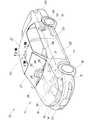
図1は本発明に係る加速度・角速度センサユニットを採用した車両の斜視図であり、10は車両、11は車体、13はフロントバンパ、14はフロントグリル、15は前照灯、16はボンネット、17はフロントフェンダ、18は前輪、19は後輪、21はルーフ、22は前ドア、23は後ドア、24,24はドアミラー、25はリヤバンパ、26フロントワイパ、27はフロントウインド、31は制御部(ECU;Electronic Control Unit)、32はエンジン、33はリヤブレーキ、34はリヤペンション、35はパワーステアリング、36はエアバッグ、50は加速度・角速度センサユニットとしての車両の加速度・角速度センサユニット(以下「センサユニット50」と略記する)を示す。The best mode for carrying out the present invention will be described below with reference to the accompanying drawings. The drawings are viewed in the direction of the reference numerals.
FIG. 1 is a perspective view of a vehicle employing an acceleration / angular velocity sensor unit according to the present invention. 10 is a vehicle, 11 is a vehicle body, 13 is a front bumper, 14 is a front grille, 15 is a headlamp, 16 is a bonnet, 17 is a front fender, 18 is a front wheel, 19 is a rear wheel, 21 is a roof, 22 is a front door, 23 is a rear door, 24 and 24 are door mirrors, 25 is a rear bumper, 26 is a front wiper, 27 is a front window, and 31 is a control. ECU (Electronic Control Unit), 32 is an engine, 33 is a rear brake, 34 is a rear pension, 35 is a power steering, 36 is an airbag, 50 is an acceleration / angular velocity sensor unit (acceleration / angular velocity sensor unit) (Hereinafter abbreviated as “
本発明に係るセンサユニット50は、車両10の重心位置付近に配置するユニットであって、実装密度の向上を図ることができるとともに実装精度の向上を図ることができるユニットである。また、センサユニット50は、自己診断を作用を有するユニットでもある。なお、車両10の前後方向をX軸、車両10の幅方向をY軸、車両10の上下方向をZ軸と定義する。以下その詳細を説明する。 The
図2は本発明に係る加速度・角速度センサユニット採用した車両の周辺装置のブロック図である。
車両の周辺装置40は、車両の加速度及び角速度を検出するセンサユニット50と、車両10(図1参照)の左右の前輪18,18の速度を検出する第1・第2車輪速度センサ41,42と、車両10の左右の後輪19,19の速度を検出する第3・第4車輪速度センサ43,44と、GSP衛星(Global Positioning System)からの信号で車両案内をするナビゲーションシステム45と、車両の横滑りを防止する横滑り制御システム46と、前車両との車間距離を一定に保つ若しくは一定の車速に保つ等の車両制御を行うアダプティブクルーズ制御システム(オートクルーズ制御システム)47と、ナビゲーションシステムやセンサユニットの異常(故障表示)などの車両情報を表示する表示システム48と、これらのセンサユニット50、第1〜第4車輪速度センサ41〜44、データナビゲーションシステム45、横滑り制御システム46及びアダプティブクルーズ制御システム47及び表示システム48を接続するLAN(Local Area Network)49と、からなる。FIG. 2 is a block diagram of a vehicle peripheral device employing the acceleration / angular velocity sensor unit according to the present invention.
The vehicle
第1・第2車輪速度センサ41,42は、それぞれ左駆動輪速度VDL及び左駆動輪速度VDRを検出し、第3・第4車輪速度センサ43,44は、それぞれ左従動輪速度VVL及び右従動輪速度VVRを検出する。 The first and second
ナビゲーションシステム45は、GPS衛星からのGPS信号により得ることのできるる位置データ、センサユニット50(加速度センサ及び角速度センサ)の出力を積分することで算出する位置データ、及び予めナビゲーションシステム45内に蓄積した地図情報に基づいて、車両10(図1参照)の現在位置を、案内情報及び地図情報とともに表示システム48に表示するものである。 The
横滑り制御システム46は、操舵角や車速から定まる目標値、及びヨーレートや横加速度等の検出値を比較すすることで、車両10のオーバステア状態やアンダーステア状態などの挙動を判定し、その判定結果に基づいてオーバステアやアンダーステアを打ち消すように(検出値が目標値に近づくように)、例えば、旋回外側の車輪にブレーキをかけたり、旋回内側の車輪にブレーキをかけたり等で車両の横滑りを制御するものである。 The
アダプティブクルーズ制御システム47は、車間距離センサ(図示せず)を備え、オートクルーズ走行などの一定車速制御に加えて、車間距離が安全車間距離以下に達したときに、シフトダウンを行う若しくは自動ブレーキをかけるなどの制御を行うものである。 The adaptive
表示システム48は、ナビゲーションシステム45からの情報、及びその他の車両情報を表示する液晶表示装置である。 The
図3は本発明に係る加速度・角速度センサユニットのブロック図であり、センサユニット50は、車両10(図1参照)のX軸(前後軸)方向の加速度を検出するX方向加速度センサとしての前後Gセンサ(前後加速度センサ)51と、車両10のY軸(左右軸)方向の加速度を検出するY方向加速度センサとしての左右Gセンサ(左右加速度センサ)52と、車両10のZ軸(上下軸)方向の加速度を検出するZ方向加速度センサとしての上下Gセンサ(上下加速度センサ)53と、X軸まわりの角速度であるロールレートを検出するX軸角速度センサとしてのロールレートセンサ54と、Y軸まわりの角速度であるピッチレートを検出するY軸角速度センサとしてのピッチレートセンサ55と、Z軸まわりの角速度であるヨーレートを検出するZ軸角速度センサとしてのヨーレートセンサ56と、これらのセンサ51〜56の情報を演算するプロセッサ(演算部)57と、からなる。 FIG. 3 is a block diagram of an acceleration / angular velocity sensor unit according to the present invention. The
なお、これらのセンサ51〜56及びプロセッサ(演算部)57は、後述する基板61(図5参照)に搭載するものである。
前後Gセンサ51、左右Gセンサ及び上下Gセンサは、9.8mm/sec2程度の分解能を有する車載用の一般的な低加速度センサである。The
The front-
ロールレートセンサ54及びピッチレートセンサ55は、中点電位の安定性がそれほど高くない比較的安価なセンサである。ロールレートセンサ54及びピッチレートセンサ55で検出するロールレートφ及びピッチレートθは、常時継続的に発生することがないので、検出信号にハイパスフィルタを施して使用することできることに基づく。 The
ヨーレートセンサ56は、横滑り制御等で直接制御に用いるヨーレートωを検出するセンサであり、中点電位(静止時)の安定性が重要な因子となるので、従来から横滑り制御に用いる比較的高価な±1deg/sec程度の安定性を確保できるセンサである。 The
プロセッサ(演算部)57は、センサ51〜56の出力信号をアナログ信号をディジタル信号に変換するA/D変換素子71と、後述する各種演算処理を実行するCPU(Central Processing Unit)72と、演算プログラムなどを記憶するROM(Read Only Memory)及び演算データを格納するRAM(Random Access Memory)からなるメモリ回路73と、LAN49(図2参照)を介して他のシステムとの間でデータの伝送を行うインタフェース回路74と、表示システム48に信号を供給する表示出力回路75と、車両走行中の検出データを記録するデータ記録装置76と、からなる。 The processor (arithmetic unit) 57 includes an A /
CPU72は、センサ51〜56で検出する検出データ(出力信号)に基づいて、前後方向の加速度、前後方向の速度、左右方向の加速度、左右方向の速度、上下方向の加速度、上下方向の速度、及び車体のX軸(前後軸)まわりの傾斜角であるロール角Φ、車体のY軸(左右軸)まわりの傾斜角であるピッチ角Θ、及び車体のZ軸(上下軸)まわりの回転角であるヨー角Ωを算出し、算出した各種データを、LAN49を介して図2に示すナビゲーションシステム45、横滑り制御システム46、アダプティブクルーズ制御システム47及び表示システム48に供給する。 Based on the detection data (output signal) detected by the
図4は本発明に係る加速度・角速度センサユニットのプロセッサの(CPU)の演算処理を説明するブロック図であり、プロセッサ57(図3参照)のCPU72は、前後速度算出部101、ピッチ角算出部102、純前後加速度算出部103、純前後速度算出部104、左右速度算出部105、ロール角算出部106、純左右加速度算出部107、純左右速度算出部108、上下速度算出部109、全傾斜角算出部110、積分全傾斜角算出部111、静止全傾斜角算出部112、座標変換部113、積分ピッチ角算出部114、積分ロール角算出部115、積分ヨー角算出部116、左右加速度算出部117及び故障診断手段としての第1〜第3の故障診断手段121〜123の機能ブロックの演算処理を実行するものである。 FIG. 4 is a block diagram for explaining the arithmetic processing of the (CPU) of the processor of the acceleration / angular velocity sensor unit according to the present invention. The
前後Gセンサ51(図3参照)、左右Gセンサ52及び上下Gセンサ53で、前後加速度a、左右加速度b及び上下加速度cが検出する。また、ピッチレートセンサ55、ロールレートセンサ54、及びヨーレートセンサ56により、ピッチレートθ、ロールレートφ、及びヨーレートωが検出する。 The longitudinal acceleration a, the lateral acceleration b, and the vertical acceleration c are detected by the longitudinal G sensor 51 (see FIG. 3), the
座標変換部113は、座標変換演算を実行し、変換ピッチレートθr、変換ロールレートφr及び変換ヨーレートωrを算出する。積分ピッチ角算出部114は、変換ピッチレートθrを積分することにより、積分ピッチ角Θを算出する。積分ロール角算出部115は、変換ロールレートφrを積分することにより、積分ロール角Φを算出する。積分ヨー角算出部116は、変換ヨーレートωrを積分することにより、積分ヨー角Ωを算出する。 The coordinate
前後速度算出部101は、検出前後加速度aを積分することにより、前後速度Uを算出する。ピッチ角算出部102は、下記式(1)により、ピッチ角αを算出する。
α=asin(a/g) (1)
ここで、asinはサイン(sin)の逆関数であり、gは重力加速度である。The longitudinal
α = asin (a / g) (1)
Here, asin is an inverse function of sine and g is gravitational acceleration.
純前後加速度算出部103は、下記式(2)に検出前後加速度a及び積分ピッチ角Θを適用し、純前後加速度Aを算出する。式(2)により、車両の左右軸(Y軸)まわりの傾きに起因する前後加速度の検出誤差が補正する。
A=a−g×sin(Θ) (2)
純前後速度算出部104は、純前後加速度Aを積分することにより、純前後速度Ucを算出する。The pure longitudinal
A = a−g × sin (Θ) (2)
The pure longitudinal
左右速度算出部105は、検出左右加速度bを積分することにより、左右速度Vを算出する。ロール角算出部106は、下記式(3)により、ロール角βを算出する。
β=asin(b/g) (3)
純左右加速度算出部107は、下記式(4)に検出左右加速度bび積分ロール角Φを適用し、純左右加速度Bを算出する。式(4)により、車両の前後軸(X軸)まわりの傾きに起因する左右加速度の検出誤差が補正する。
B=b−g×sin(Φ) (4)The left-right
β = asin (b / g) (3)
The pure left / right
B = b−g × sin (Φ) (4)
純左右速度算出部108は、純左右加速度Bを積分することにより、純左右速度Vcを算出する。上下速度算出部109は、検出上下加速度cを積分することにより、上下速度Wを算出する。 The pure left-right
全傾斜角算出部110は、下記式(5)に検出上下加速度cを適用し、全傾斜角γを算出する。
γ=acos(c/g) (5)
静止全傾斜角算出部112は、車両の停車時に検出されるピッチ角α及びロール角βを下記式(6)に適用し、静止全傾斜角γ’を算出する。車両の停止状態は、例えば純前後速度Ucが「0」であることにより検出する。
γ’=acos(cosα×cosβ) (6)The total inclination
γ = acos (c / g) (5)
The static total inclination angle calculation unit 112 applies the pitch angle α and the roll angle β detected when the vehicle is stopped to the following equation (6) to calculate the static total inclination angle γ ′. The stop state of the vehicle is detected, for example, when the pure longitudinal speed Uc is “0”.
γ ′ = acos (cos α × cos β) (6)
積分全傾斜角算出部111は、下記式(6a)に静止全傾斜角γ’、積分ピッチ角Θ及び積分ロール角Φを適用し、積分全傾斜角Γを算出する。
Γ=γ’+acos(cosΘ×cosΦ) (6a)
ここで、静止全傾斜角γ’を適用するのは初期値補正を行うためである。ロールレートセンサ54及びピッチレートセンサ55は、車両の停止時は出力が「0」であるため、車両停止時において路面が傾斜している場合には、積分全傾斜角Γは、正確な全傾斜角とならない。そこで、静止全傾斜角γ’を加算することにより、初期値補正が行われる。これにより、正確な積分全傾斜角を得ることができる。The integral total inclination
Γ = γ ′ + acos (cos Θ × cos Φ) (6a)
Here, the reason why the static total inclination angle γ ′ is applied is to perform initial value correction. Since the output of the
第1の故障診断手段121は、全傾斜角γと積分全傾斜角Γとの比較を常時行い、両者の差(γ−Γ)の絶対値が所定しきい値DGAMMA1を超えたとき、上下Gセンサ53(図3参照)、ロールレートセンサ54またはピッチレートセンサ55のいずれかが故障したと判定する。 The first failure diagnosis means 121 always compares the total inclination angle γ with the integrated total inclination angle Γ, and when the absolute value of the difference (γ−Γ) exceeds a predetermined threshold value DGAMMA1, the upper and lower G It is determined that one of the sensor 53 (see FIG. 3), the
第3の故障診断手段123は、車両の停止時において、全傾斜角γと静止全傾斜角γ’との比較を行い、両者の差(γ−γ’)の絶対値が所定しきい値DGAMMA2を超えたとき、前後G度センサ51(図3参照)、左右Gセンサ52、または上下Gセンサ53のいずれかが故障したと判定する。 The third failure diagnosis means 123 compares the total inclination angle γ and the stationary total inclination angle γ ′ when the vehicle is stopped, and the absolute value of the difference (γ−γ ′) between them is a predetermined threshold value DGAMMA2. Is exceeded, it is determined that any one of the front / rear G degree sensor 51 (see FIG. 3), the left /
左右加速度算出部117は、ヨーレートω及び純前後速度Ucを下記式(7)に適用し、左右加速度Rを算出する。
R=ω×Uc (7)
第2の故障診断手段122は、純左右加速度Bと左右加速度Rとの比較を常時行い、両者の差(B−R)の絶対値が所定しきい値DBRを超えたとき、前後Gセンサ51(図3参照)、左右Gセンサ52、ロールレートセンサ54、またはヨーレートセンサ56のいずれかが故障したと判定する。The lateral
R = ω × Uc (7)
The second failure diagnosis means 122 always compares the pure left / right acceleration B and the left / right acceleration R, and when the absolute value of the difference (B−R) exceeds a predetermined threshold value DBR, the front /
すなわち、センサユニット50(図3参照)は、図5に示す基板61に、前後Gセンサ(X方向加速度センサ)51、左右Gセンサ(Y方向加速度センサ)52、上下Gセンサ(Z方向加速度センサ)53、ロールレートセンサ(X軸角速度センサ)54、ピッチレートセンサ(Y軸角速度センサ)55及びヨーレートセンサ(Z軸角速度センサ)56の各検出値を処理するプロセッサ57を実装し、このプロセッサ57に、前後Gセンサ51、左右Gセンサ52、上下Gセンサ53、ロールレートセンサ54、ピッチレートセンサ55及びヨーレートセンサ56の故障を診断する第1〜第3の故障診断手段121〜123を備えたものと言える。 That is, the sensor unit 50 (see FIG. 3) includes a front and rear G sensor (X direction acceleration sensor) 51, a left and right G sensor (Y direction acceleration sensor) 52, and a vertical G sensor (Z direction acceleration sensor) on the
プロセッサ57に、前後Gセンサ51、左右Gセンサ52、上下Gセンサ53、ロールレートセンサ54、ピッチレートセンサ55及びヨーレートセンサ56の故障を診断する第1〜第3の故障診断手段121〜123を備えることで、前後Gセンサ51、左右Gセンサ52、上下Gセンサ53、ロールレートセンサ54、ピッチレートセンサ55及びヨーレートセンサ56の故障を迅速に見つけることができる。この結果、車両10(図1参照)のメンテナンス性の向上を図ることができる The
次に、センサユニット50の部品マウント構造を説明する。
図5は本発明に係る加速度・角速度センサユニットの平面図であり、図6は本発明に係る加速度・角速度センサユニットの底面図である。
センサユニット50は、略矩形の基板61と、この基板61の表面61aに搭載した上下加速度(Z軸廻り加速度)を検出する上下Gセンサ53と、基板61の表面61aに搭載した上下角速度(Z軸廻りの角速度;ヨーレート)を検出するヨーレートセンサ56と、基板61の表面61aに搭載することで信号処理をするプロセッサ57と、基板61の表面61aに搭載することでプロセッサ57などに電源を供給する電源IC(Integrated Circuit)62と、基板61の表面61aに搭載することでLAN49(図2参照)を構築するCAN(Controller Area Network)トランシーバ63と、基板61の表面61aに搭載した端子64と、図6に示すように、基板61の裏面61bに搭載した前後加速度を検出する前後加速度(X軸廻り加速度)を検出する前後Gセンサ51と、基板61の裏面61bに搭載した左右加速度(Y軸廻り加速度)を検出するの左右Gセンサ52と、基板61の裏面61bに搭載した左右角速度(X軸廻り角速度;ロールレート)ロールレートセンサ54と、基板61の裏面61bに搭載した前後角速度(Y軸廻り角速度;ピッチレート)ピッチレートセンサ55と、基板61の裏面61bに搭載した抵抗、コンデンサなどの複数の受動部品65と、からなる。なお、基板61は両面基板である。Next, the component mounting structure of the
FIG. 5 is a plan view of the acceleration / angular velocity sensor unit according to the present invention, and FIG. 6 is a bottom view of the acceleration / angular velocity sensor unit according to the present invention.
The
上下Gセンサ53及びヨーレートセンサ56は、基板61の表面61aに搭載するときに近接させて配置し、前後Gセンサ51及び左右Gセンサ52は、基板61の裏面61bに搭載するときに近接させて配置し、ロールレートセンサ54及びピッチレートセンサ55は、基板61の裏面61bに搭載するときに近接させて配置したものである。 The
センサユニット50は、互いに直交するX軸、Y軸、Z軸の、X軸方向の加速度を検出する前後Gセンサ(X方向加速度センサ)51と、Y軸方向の加速度を検出する左右Gセンサ(Y方向加速度センサ)52と、Z軸方向の加速度を検出する上下Gセンサ(Z方向加速度センサ)53と、X軸まわりの角速度を検出するロールレートセンサ(X軸角速度センサ)54と、Y軸まわりの角速度を検出するピッチレートセンサ(Y軸角速度センサ)55と、Z軸まわりの角速度を検出するヨーレートセンサ(Z軸角速度センサ)56と、を同一の基板に実装する加速度及び角速度センサユニットであって、基板61の裏面61bに、X軸およびY軸が平行となるように前後Gセンサ51、ロールレートセンサ54、左右Gセンサ52およびピッチレートセンサ55を実装し、Z軸が垂直となるように基板61の表面61aに、上下Gセンサ53およびヨーレートセンサ56を実装したものと言える。 The
すなわち、基板61の裏面61bに、X軸およびY軸が平行となるように前後Gセンサ51、ロールレートセンサ54、左右Gセンサ52およびピッチレートセンサ55を実装し、Z軸が垂直となるように基板61の表面61aに、上下Gセンサ53およびヨーレートセンサ56を実装することで、基板61の実装密度を向上することができる。この結果、センサユニット50の小型化を図ることができる。 That is, the front /
また、基板61の裏面61bに、X軸およびY軸が平行となるように前後Gセンサ51、ロールレートセンサ54、左右Gセンサ52およびピッチレートセンサ55を実装し、Z軸が垂直となるように基板61の表面61aに、上下Gセンサ53およびヨーレートセンサ56を実装することで、前後Gセンサ51、ロールレートセンサ54、左右Gセンサ52およびピッチレートセンサ55に対する上下Gセンサ53およびヨーレートセンサ56の垂直精度の向上を図ることができる。この結果、センシングの精度の向上を図ることができる。 Further, the front /
言い換えれば、センサユニット50は、車両10(図1参照)の前後方向をX軸、左右方向をY軸、上下方向をZ軸とするときに、車両10の前後方向の加速度を検出する前後Gセンサ(X方向加速度センサ)51と、車両10の左右方向の加速度を検出する左右Gセンサ(Y方向加速度センサ)52と、車両10の上下方向の加速度を検出する上下Gセンサ(Z方向加速度センサ)53と、X軸まわりの角速度を検出するロールレートセンサ(X軸角速度センサ)54と、Y軸まわりの角速度を検出するピッチレートセンサ(Y軸角速度センサ)55と、Z軸まわりの角速度を検出するヨーレートセンサ(Z軸角速度センサ)56と、を同一の基板61に実装する加速度及び角速度センサユニットであって、基板61の前後、左右、上下をそれぞれ図1に示すX軸、Y軸、Z軸に沿わせて車両10に基板61を実装するときに、基板61の裏面61bに、前後Gセンサ51及びロールレートセンサ54をX軸に平行に実装し、且つ左右Gセンサ52及びピッチレートセンサ55をY軸に平行に実装するとともに、前後Gセンサ51及び左右Gセンサ52を近接させ、且つロールレートセンサ54及びピッチレートセンサ55を近接させて実装し、基板61の表面61aに、上下Gセンサ53及びヨーレートセンサ56をZ軸に垂直に実装するとともに、上下Gセンサ53及びヨーレートセンサ56を近接させ実装したものと言える。 In other words, the
例えば、基板の実装密度を向上させることのできるとすれば、加速度・角速度センサユニットを小型にすることができるので好都合であり、センサの実装精度の向上を図ることのできるとすれば、センシングの精度の向上を図ることができるので好ましいことである。 For example, if the mounting density of the substrate can be improved, it is convenient because the acceleration / angular velocity sensor unit can be reduced in size, and if the mounting accuracy of the sensor can be improved, sensing can be improved. This is preferable because accuracy can be improved.
そこで、基板61の裏面61bに、前後Gセンサ51及びロールレートセンサ54をX軸に平行に実装し、且つ左右Gセンサ52及びピッチレートセンサ55をY軸に平行に実装するとともに、前後Gセンサ51及び左右Gセンサ52を近接させ、且つロールレートセンサ54及びピッチレートセンサ55を近接させて実装し、基板61の表面61aに、上下Gセンサ53及びヨーレートセンサ56をZ軸に垂直に実装するとともに、上下Gセンサ53及びヨーレートセンサ56を近接させ実装することで、基板61の表面61a及び裏面61bの実装密度のバランスを保つことができる。
これにより、基板61の実装密度を上げることができる。この結果、車両10(図1参照)のセンサユニット50の小型化を図ることができる。Therefore, the front and
Thereby, the mounting density of the board |
また、センサユニット50は、前後Gセンサ51及び左右Gセンサ52を近接させ、且つロールレートセンサ54及びピッチレートセンサ55を近接さて実装するとともに、
上下Gセンサ53及びヨーレートセンサ56を近接させ実装することで、基板61の反りなどの影響を受けにくくすることができる。これにより、相互に関連する前後Gセンサ51及び左右Gセンサ52同士の位置精度を保つことができ、相互に関連するロールレートセンサ54及びピッチレートセンサ55同士の位置精度を保つことができ、相互に関連する上下Gセンサ53及びヨーレートセンサ56同士の位置精度を保つことができる。この結果、センサ51〜56の実装精度の向上を図ることのでき、センシングの精度の向上を図ることができる。The
By mounting the
センサユニット50は、先に説明したように、第1〜第3の故障診断手段121〜123(図4参照)を備えたので、システム45〜47の信頼性の向上を図ることもできる。 As described above, since the
センサユニット50は、複数のセンサ51〜56を一つのユニットにまとめ、図2に示したようにナビゲーションシステム45、横滑り制御システム46やアダプティブクルーズ制御システム47などの複数のシステムで共用して使用することができる。この結果、システム45〜47の簡素化を図ることができる。また、ナビゲーションシステム45、横滑り制御システム46やアダプティブクルーズ制御システム47で個別に故障診断をする必要もなく、システム45〜47のメンテナンス性の向上をも図ることができる。 The
尚、本発明に係る加速度・角速度センサユニットは、図5及び図6に示すように、基板61の裏面61bに、前後Gセンサ51及びロールレートセンサ54を実装し、且つ左右Gセンサ52及びピッチレートセンサ55を実装するとともに、基板61の表面61aに、上下Gセンサ53及びヨーレートセンサ56を実装したが、これに限るものではなく、基板61の表面61aに、前後Gセンサ51及びロールレートセンサ54を実装し、且つ左右Gセンサ52及びピッチレートセンサ55を実装するとともに、基板61の裏面61bに、上下Gセンサ53及びヨーレートセンサ56を実装したものであってもよい。 As shown in FIGS. 5 and 6, the acceleration / angular velocity sensor unit according to the present invention has the front /
本発明に係る加速度・角速度センサユニットは、図1に示すように、車両の加速度・角速度センサユニット50(センサユニット50)であったが、これに限るものではなく、加速度・角速度センサユニットは車両に限定するものではない。 As shown in FIG. 1, the acceleration / angular velocity sensor unit according to the present invention is a vehicle acceleration / angular velocity sensor unit 50 (sensor unit 50). However, the present invention is not limited to this. It is not limited to.
本発明に係る加速度・角速度センサユニットは、ナビゲーションシステム、横滑り制御システム、オートクルーズ制御システムなどのシステムを搭載する車両に採用するのに好適である。 The acceleration / angular velocity sensor unit according to the present invention is suitable for use in a vehicle equipped with a system such as a navigation system, a skid control system, and an auto cruise control system.
10…車両、50…加速度・角速度センサユニット(車両の加速度・角速度センサユニット)、51…X方向加速度センサ(前後Gセンサ)、52…Y方向加速度センサ(左右Gセンサ)、53…Z方向加速度センサ(上下Gセンサ)、54…X軸角速度センサ(ロールレートセンサ)、55…Y軸角速度センサ(ピッチレートセンサ)、56…Z軸角速度センサ(ヨーレートセンサ)、57…プロセッサ、61…基板、61a…表面、61b…の裏面、121〜123…故障診断手段(第1〜第3の故障診断手段)。 DESCRIPTION OF
Claims (2)
Translated fromJapanese前記基板の表面若しくは裏面のいずれかの一方側に、前記X軸およびY軸が平行となるように前記X方向加速度センサ、前記X軸角速度センサ、前記Y軸方向加速度センサおよび前記Y軸角速度センサを実装し、
前記基板の裏面若しくは表面のいずれかの他方側に、前記Z軸が垂直となるように前記Z方向加速度センサ、前記Z軸角速度センサを実装したことを特徴とする加速度・角速度センサユニット。An X-direction acceleration sensor that detects acceleration in the X-axis direction of the X-axis, Y-axis, and Z-axis that are orthogonal to each other, a Y-direction acceleration sensor that detects acceleration in the Y-axis direction, and a Z that detects acceleration in the Z-axis direction A direction acceleration sensor, an X-axis angular velocity sensor that detects an angular velocity around the X-axis, a Y-axis angular velocity sensor that detects an angular velocity around the Y-axis, a Z-axis angular velocity sensor that detects an angular velocity around the Z-axis, Is an acceleration and angular velocity sensor unit mounted on the same substrate,
The X-direction acceleration sensor, the X-axis angular velocity sensor, the Y-axis direction acceleration sensor, and the Y-axis angular velocity sensor so that the X-axis and the Y-axis are parallel to one side of either the front surface or the back surface of the substrate Implement
An acceleration / angular velocity sensor unit, wherein the Z-direction acceleration sensor and the Z-axis angular velocity sensor are mounted so that the Z-axis is perpendicular to either the back surface or the front surface of the substrate.
このプロセッサは、前記X方向加速度センサ、Y方向加速度センサ、Z方向加速度センサ、X軸角速度センサ、Y軸角速度センサ及びZ軸角速度センサの故障を診断する故障診断手段を備えたことを特徴とする請求項1記載の加速度・角速度センサユニット。
A processor for processing each detection value of the X direction acceleration sensor, the Y direction acceleration sensor, the Z direction acceleration sensor, the X axis angular velocity sensor, the Y axis angular velocity sensor, and the Z axis angular velocity sensor is mounted on the substrate,
The processor includes failure diagnosis means for diagnosing a failure of the X-direction acceleration sensor, Y-direction acceleration sensor, Z-direction acceleration sensor, X-axis angular velocity sensor, Y-axis angular velocity sensor, and Z-axis angular velocity sensor. The acceleration / angular velocity sensor unit according to claim 1.
Priority Applications (3)
| Application Number | Priority Date | Filing Date | Title |
|---|---|---|---|
| JP2004288361AJP2006105598A (en) | 2004-09-30 | 2004-09-30 | Acceleration / Angular velocity sensor unit |
| US11/239,867US7325454B2 (en) | 2004-09-30 | 2005-09-30 | Acceleration/angular velocity sensor unit |
| DE102005046986ADE102005046986B4 (en) | 2004-09-30 | 2005-09-30 | Acceleration / angular velocity sensor unit |
Applications Claiming Priority (1)
| Application Number | Priority Date | Filing Date | Title |
|---|---|---|---|
| JP2004288361AJP2006105598A (en) | 2004-09-30 | 2004-09-30 | Acceleration / Angular velocity sensor unit |
Publications (1)
| Publication Number | Publication Date |
|---|---|
| JP2006105598Atrue JP2006105598A (en) | 2006-04-20 |
Family
ID=36089060
Family Applications (1)
| Application Number | Title | Priority Date | Filing Date |
|---|---|---|---|
| JP2004288361APendingJP2006105598A (en) | 2004-09-30 | 2004-09-30 | Acceleration / Angular velocity sensor unit |
Country Status (3)
| Country | Link |
|---|---|
| US (1) | US7325454B2 (en) |
| JP (1) | JP2006105598A (en) |
| DE (1) | DE102005046986B4 (en) |
Cited By (4)
| Publication number | Priority date | Publication date | Assignee | Title |
|---|---|---|---|---|
| KR100887737B1 (en)* | 2008-07-18 | 2009-03-12 | 주식회사 엠투엠코리아 | 6 degree of freedom detection sensor |
| JP2010184691A (en)* | 2009-02-13 | 2010-08-26 | Honda Motor Co Ltd | Angular velocity sensor unit of small vehicle |
| DE102013102425A1 (en) | 2012-03-14 | 2013-09-19 | Denso Corporation | Collision detection device for a vehicle |
| JP2022104276A (en)* | 2020-12-28 | 2022-07-08 | 本田技研工業株式会社 | Abnormality judgment device, abnormality judgment method, abnormality judgment program, and vehicle condition estimation device |
Families Citing this family (32)
| Publication number | Priority date | Publication date | Assignee | Title |
|---|---|---|---|---|
| US7590481B2 (en)* | 2005-09-19 | 2009-09-15 | Ford Global Technologies, Llc | Integrated vehicle control system using dynamically determined vehicle conditions |
| JP2007248328A (en)* | 2006-03-17 | 2007-09-27 | Matsushita Electric Ind Co Ltd | Compound sensor |
| JP5043358B2 (en)* | 2006-04-04 | 2012-10-10 | ラピスセミコンダクタ株式会社 | Inclination angle calculation method and inclination angle calculation device |
| WO2008019698A1 (en)* | 2006-08-14 | 2008-02-21 | Cherif Atia Algreatly | Motion tracking apparatus and method |
| DE102006049118B4 (en)* | 2006-10-18 | 2008-12-18 | Continental Automotive Gmbh | Method and device for determining a signal offset of a pitch rate sensor |
| US20100071467A1 (en)* | 2008-09-24 | 2010-03-25 | Invensense | Integrated multiaxis motion sensor |
| US8508039B1 (en) | 2008-05-08 | 2013-08-13 | Invensense, Inc. | Wafer scale chip scale packaging of vertically integrated MEMS sensors with electronics |
| US8020441B2 (en)* | 2008-02-05 | 2011-09-20 | Invensense, Inc. | Dual mode sensing for vibratory gyroscope |
| US20090262074A1 (en)* | 2007-01-05 | 2009-10-22 | Invensense Inc. | Controlling and accessing content using motion processing on mobile devices |
| US8250921B2 (en)* | 2007-07-06 | 2012-08-28 | Invensense, Inc. | Integrated motion processing unit (MPU) with MEMS inertial sensing and embedded digital electronics |
| US20090265671A1 (en)* | 2008-04-21 | 2009-10-22 | Invensense | Mobile devices with motion gesture recognition |
| US7934423B2 (en) | 2007-12-10 | 2011-05-03 | Invensense, Inc. | Vertically integrated 3-axis MEMS angular accelerometer with integrated electronics |
| US8141424B2 (en)* | 2008-09-12 | 2012-03-27 | Invensense, Inc. | Low inertia frame for detecting coriolis acceleration |
| US8462109B2 (en) | 2007-01-05 | 2013-06-11 | Invensense, Inc. | Controlling and accessing content using motion processing on mobile devices |
| US8047075B2 (en)* | 2007-06-21 | 2011-11-01 | Invensense, Inc. | Vertically integrated 3-axis MEMS accelerometer with electronics |
| US8952832B2 (en)* | 2008-01-18 | 2015-02-10 | Invensense, Inc. | Interfacing application programs and motion sensors of a device |
| CN101583844B (en)* | 2007-01-18 | 2011-11-09 | 三菱电机株式会社 | Car navigation device |
| US8006557B2 (en)* | 2007-05-16 | 2011-08-30 | Intellisense Software Corporation | Multi-axis sensor |
| FR2925669B1 (en)* | 2007-12-21 | 2010-01-15 | Sagem Defense Securite | MEASUREMENT BY GYROSCOPIC SYSTEM |
| US20090187324A1 (en) | 2008-01-23 | 2009-07-23 | Jianbo Lu | Vehicle Stability Control System and Method |
| US8295992B2 (en)* | 2008-03-27 | 2012-10-23 | Hetronic International, Inc. | Remote control system having a touchscreen for controlling a railway vehicle |
| FR2937414B1 (en)* | 2008-10-20 | 2010-11-26 | Sagem Defense Securite | GYROSCOPIC MEASUREMENT BY A VIBRANT GYROSCOPE |
| US8326494B2 (en)* | 2008-10-24 | 2012-12-04 | GM Global Technology Operations LLC | Method and apparatus for determining a desired yaw rate for a vehicle |
| JP5318720B2 (en)* | 2009-09-30 | 2013-10-16 | 富士通テン株式会社 | Electronic control unit |
| US9403415B2 (en)* | 2009-10-12 | 2016-08-02 | Ford Global Technologies | GPS based pitch sensing for an integrated stability control system |
| JP2011203028A (en)* | 2010-03-25 | 2011-10-13 | Hitachi Automotive Systems Ltd | Device for detecting angular velocity and acceleration |
| DE102010027969B4 (en)* | 2010-04-20 | 2020-07-02 | Robert Bosch Gmbh | Method and device for determining a type of impact of an object on a vehicle |
| US10207719B2 (en)* | 2010-07-19 | 2019-02-19 | Nxp Usa, Inc. | Use of multiple internal sensors for measurements validation |
| ITVR20110210A1 (en)* | 2011-11-24 | 2013-05-25 | Cefriel Societa Consortile A Respon Sabilita Limit | IMPACT DETECTION DEVICE. |
| US9085236B2 (en)* | 2013-05-09 | 2015-07-21 | Robert Bosch Gmbh | Adaptive cruise control with stationary object recognition |
| JP7127292B2 (en)* | 2018-02-14 | 2022-08-30 | オムロン株式会社 | Sensor unit, control method, program, and recording medium |
| JP7235015B2 (en)* | 2020-07-17 | 2023-03-08 | トヨタ自動車株式会社 | automatic steering system |
Citations (12)
| Publication number | Priority date | Publication date | Assignee | Title |
|---|---|---|---|---|
| JPS6088311A (en)* | 1983-09-16 | 1985-05-18 | ジーイーシー・フェランティ・デフェンス・システムス・リミテッド | Accelerometer system |
| JPH06347264A (en)* | 1993-06-10 | 1994-12-20 | Hitachi Cable Ltd | Inclination sensor |
| JPH07128357A (en)* | 1993-11-09 | 1995-05-19 | Murata Mfg Co Ltd | Acceleration sensor |
| JPH07270446A (en)* | 1994-02-09 | 1995-10-20 | Toyota Motor Corp | Vehicle condition estimation device |
| JPH109889A (en)* | 1996-06-20 | 1998-01-16 | Tamagawa Seiki Co Ltd | Inertial sensor device |
| JPH10239064A (en)* | 1997-02-27 | 1998-09-11 | Matsushita Electric Ind Co Ltd | Composite sensor of angular velocity and acceleration |
| JP2001033479A (en)* | 1999-07-27 | 2001-02-09 | Japan Aviation Electronics Industry Ltd | Inertial measurement device |
| JP2002014112A (en)* | 2000-06-27 | 2002-01-18 | Matsushita Electric Ind Co Ltd | Piezoelectric acceleration sensor |
| JP2002013936A (en)* | 2000-06-28 | 2002-01-18 | Ngk Insulators Ltd | Navigation device for vehicle and pedestal for installing and charging portable information terminal apparatus |
| JP2003043063A (en)* | 2001-08-01 | 2003-02-13 | Nagano Fujitsu Component Kk | Acceleration detector |
| JP2003072600A (en)* | 2001-09-04 | 2003-03-12 | Tamagawa Seiki Co Ltd | Vehicle behavior information recording method and apparatus |
| JP2004150973A (en)* | 2002-10-31 | 2004-05-27 | Honda Motor Co Ltd | Vehicle acceleration detector |
Family Cites Families (10)
| Publication number | Priority date | Publication date | Assignee | Title |
|---|---|---|---|---|
| US5396326A (en)* | 1989-04-03 | 1995-03-07 | Northrop Grumman Corporation | Two gimbal error averaging astro-inertial navigator |
| DE19720106C2 (en)* | 1997-05-16 | 2001-03-15 | Telefunken Microelectron | Device for receiving electrical components |
| JP2000314744A (en) | 1999-05-06 | 2000-11-14 | Matsushita Electric Ind Co Ltd | Multilayer piezoelectric acceleration sensor |
| JP3736340B2 (en)* | 2000-12-14 | 2006-01-18 | トヨタ自動車株式会社 | Vehicle control device |
| DE10064170C2 (en) | 2000-12-22 | 2002-11-07 | Stn Atlas Elektronik Gmbh | Device for measuring acceleration and / or angular velocity |
| JP2002296039A (en)* | 2001-03-30 | 2002-10-09 | Murata Mfg Co Ltd | Gyro device and electronic device using the same |
| JP3579832B2 (en)* | 2001-06-07 | 2004-10-20 | 日本航空電子工業株式会社 | 3-axis acceleration / angular velocity meter |
| JP2003004450A (en)* | 2001-06-25 | 2003-01-08 | Matsushita Electric Ind Co Ltd | Composite sensor for angular velocity and acceleration detection |
| US7028546B2 (en)* | 2003-10-21 | 2006-04-18 | Instrumented Sensor Technology, Inc. | Data recorder |
| US20060250257A1 (en)* | 2005-05-09 | 2006-11-09 | Reynolds Christopher I | Sensor orientation for environmental error reduction |
- 2004
- 2004-09-30JPJP2004288361Apatent/JP2006105598A/enactivePending
- 2005
- 2005-09-30DEDE102005046986Apatent/DE102005046986B4/ennot_activeExpired - Fee Related
- 2005-09-30USUS11/239,867patent/US7325454B2/ennot_activeExpired - Fee Related
Patent Citations (12)
| Publication number | Priority date | Publication date | Assignee | Title |
|---|---|---|---|---|
| JPS6088311A (en)* | 1983-09-16 | 1985-05-18 | ジーイーシー・フェランティ・デフェンス・システムス・リミテッド | Accelerometer system |
| JPH06347264A (en)* | 1993-06-10 | 1994-12-20 | Hitachi Cable Ltd | Inclination sensor |
| JPH07128357A (en)* | 1993-11-09 | 1995-05-19 | Murata Mfg Co Ltd | Acceleration sensor |
| JPH07270446A (en)* | 1994-02-09 | 1995-10-20 | Toyota Motor Corp | Vehicle condition estimation device |
| JPH109889A (en)* | 1996-06-20 | 1998-01-16 | Tamagawa Seiki Co Ltd | Inertial sensor device |
| JPH10239064A (en)* | 1997-02-27 | 1998-09-11 | Matsushita Electric Ind Co Ltd | Composite sensor of angular velocity and acceleration |
| JP2001033479A (en)* | 1999-07-27 | 2001-02-09 | Japan Aviation Electronics Industry Ltd | Inertial measurement device |
| JP2002014112A (en)* | 2000-06-27 | 2002-01-18 | Matsushita Electric Ind Co Ltd | Piezoelectric acceleration sensor |
| JP2002013936A (en)* | 2000-06-28 | 2002-01-18 | Ngk Insulators Ltd | Navigation device for vehicle and pedestal for installing and charging portable information terminal apparatus |
| JP2003043063A (en)* | 2001-08-01 | 2003-02-13 | Nagano Fujitsu Component Kk | Acceleration detector |
| JP2003072600A (en)* | 2001-09-04 | 2003-03-12 | Tamagawa Seiki Co Ltd | Vehicle behavior information recording method and apparatus |
| JP2004150973A (en)* | 2002-10-31 | 2004-05-27 | Honda Motor Co Ltd | Vehicle acceleration detector |
Cited By (6)
| Publication number | Priority date | Publication date | Assignee | Title |
|---|---|---|---|---|
| KR100887737B1 (en)* | 2008-07-18 | 2009-03-12 | 주식회사 엠투엠코리아 | 6 degree of freedom detection sensor |
| JP2010184691A (en)* | 2009-02-13 | 2010-08-26 | Honda Motor Co Ltd | Angular velocity sensor unit of small vehicle |
| DE102013102425A1 (en) | 2012-03-14 | 2013-09-19 | Denso Corporation | Collision detection device for a vehicle |
| US8935012B2 (en) | 2012-03-14 | 2015-01-13 | Denso Corporation | Collision determination apparatus for vehicle |
| JP2022104276A (en)* | 2020-12-28 | 2022-07-08 | 本田技研工業株式会社 | Abnormality judgment device, abnormality judgment method, abnormality judgment program, and vehicle condition estimation device |
| JP7349978B2 (en) | 2020-12-28 | 2023-09-25 | 本田技研工業株式会社 | Abnormality determination device, abnormality determination method, abnormality determination program, and vehicle state estimation device |
Also Published As
| Publication number | Publication date |
|---|---|
| DE102005046986A1 (en) | 2006-04-13 |
| US7325454B2 (en) | 2008-02-05 |
| US20060065050A1 (en) | 2006-03-30 |
| DE102005046986B4 (en) | 2008-04-10 |
Similar Documents
| Publication | Publication Date | Title |
|---|---|---|
| JP2006105598A (en) | Acceleration / Angular velocity sensor unit | |
| US6782315B2 (en) | Method and apparatus for compensating misalignments of a sensor system used in a vehicle dynamic control system | |
| US6456194B1 (en) | Device and method for sensing and indicating inclination of an automotive vehicle | |
| CN101223417B (en) | Method for determining and correcting incorrect orientations and deviations of sensors of an inertial measurement unit in a land vehicle | |
| US9753144B1 (en) | Bias and misalignment compensation for 6-DOF IMU using GNSS/INS data | |
| US7451033B2 (en) | Lateral and longitudinal velocity determination for an automotive vehicle | |
| US7092808B2 (en) | Integrated sensing system for an automotive system | |
| JP4161923B2 (en) | Vehicle stabilization control system | |
| US7010409B2 (en) | Reference signal generator for an integrated sensing system | |
| US20160299234A1 (en) | Fail operational vehicle speed estimation through data fusion of 6-dof imu, gps, and radar | |
| US8695424B2 (en) | Sensor device for detecting at least one rotation rate of a rotating motion | |
| US20040148093A1 (en) | Vehicle behavior detector, in-vehicle processing system, detection information calibrator, and in-vehicle processor | |
| US8666589B2 (en) | Device and method for determining the driving state of a vehicle | |
| US11037380B2 (en) | Method and device for ascertaining an orientation of a sensor unit | |
| US7831354B2 (en) | Body state estimation of a vehicle | |
| JP4242134B2 (en) | Vehicle acceleration and angular velocity detection device | |
| US7058486B2 (en) | Method and device for determining the float angle of a motor vehicle | |
| JP7622703B2 (en) | Vehicle display control device, vehicle display device, vehicle, vehicle display control method, and vehicle display control program | |
| JP2025520292A (en) | Method for calibrating an inertial measurement sensor system of a vehicle - Patents.com | |
| JP2007161013A (en) | Wheel vertical acceleration detection device for posture correction of detection value of vertical acceleration sensor | |
| KR102637830B1 (en) | Methods, electronic control devices and systems for position determination | |
| JP5352922B2 (en) | Angular velocity calculation device, navigation device | |
| US7657395B2 (en) | Two-axis accelerometer for detecting inclination without the effect of common acceleration | |
| CN115135519A (en) | Determining dynamic quantities of a vehicle by distributed sensors | |
| US12091108B2 (en) | Methods and systems for a pitch angle recognition of a steering column in a vehicle |
Legal Events
| Date | Code | Title | Description |
|---|---|---|---|
| A977 | Report on retrieval | Free format text:JAPANESE INTERMEDIATE CODE: A971007 Effective date:20071207 | |
| A131 | Notification of reasons for refusal | Free format text:JAPANESE INTERMEDIATE CODE: A131 Effective date:20071218 | |
| A521 | Request for written amendment filed | Free format text:JAPANESE INTERMEDIATE CODE: A523 Effective date:20080214 | |
| A131 | Notification of reasons for refusal | Free format text:JAPANESE INTERMEDIATE CODE: A131 Effective date:20080527 | |
| A521 | Request for written amendment filed | Free format text:JAPANESE INTERMEDIATE CODE: A523 Effective date:20080725 | |
| A02 | Decision of refusal | Free format text:JAPANESE INTERMEDIATE CODE: A02 Effective date:20080826 |