JP2006103933A - Sheet feeding apparatus and image forming apparatus - Google Patents
Sheet feeding apparatus and image forming apparatusDownload PDFInfo
- Publication number
- JP2006103933A JP2006103933AJP2004295825AJP2004295825AJP2006103933AJP 2006103933 AJP2006103933 AJP 2006103933AJP 2004295825 AJP2004295825 AJP 2004295825AJP 2004295825 AJP2004295825 AJP 2004295825AJP 2006103933 AJP2006103933 AJP 2006103933A
- Authority
- JP
- Japan
- Prior art keywords
- sheet
- intermediate plate
- sheet feeding
- plate
- pinion gear
- Prior art date
- Legal status (The legal status is an assumption and is not a legal conclusion. Google has not performed a legal analysis and makes no representation as to the accuracy of the status listed.)
- Pending
Links
Images


Landscapes
- Sheets, Magazines, And Separation Thereof (AREA)
Abstract
Description
Translated fromJapanese本発明は、複写機、レーザービームプリンタ、ファクシミリ及びそれらの複合機等の画像形成装置において、トレイに積載されたシート束からシートを一枚ずつ画像形成装置本体内へ供給するシート給送装置に関するものである。 BACKGROUND OF THE INVENTION 1. Field of the Invention The present invention relates to a sheet feeding apparatus that supplies sheets one by one from a sheet bundle stacked on a tray to an image forming apparatus main body in an image forming apparatus such as a copying machine, a laser beam printer, a facsimile machine, or a multifunction machine thereof. Is.
従来のシート給送装置において、画像形成するシートを収納した給紙カセットの画像形成装置本体からの引き出し操作に連動して中板が自動的に押し下げられ、その押し下げられた位置で中板をロックするようにして、シートの補充、交換操作を容易にしたものがある(例えば、特許文献1参照)。 In the conventional sheet feeding device, the middle plate is automatically pushed down in conjunction with the pulling-out operation from the image forming device main body of the paper feed cassette storing the sheet for image formation, and the middle plate is locked at the pushed position. Thus, there is a sheet that facilitates sheet replenishment and replacement operations (see, for example, Patent Document 1).
さらに、中板を押し上げるための中板ばねを複数設けて、シートの側端部を規制するシート幅規制板の移動に応じてばねロック部材により選択的に中板ばねをロックするようにしたものがある。これは、給送するシートのサイズが大きい場合には、ばねロック部材による中板ばねのロックを行なわずに全ての中板ばねで中板を付勢することにより高い給紙圧を発生させ、給送するシートのサイズが小さい場合には、シート幅規制板の移動によりばねロック部材により一つの中板ばねをロックすることにより低い給紙圧を発生させるものである。これによりシートのサイズに応じた最適な給紙圧によってシートを給送することができ、給送不良等の発生を防止できる。 Furthermore, a plurality of middle plate springs for pushing up the middle plate are provided, and the middle plate spring is selectively locked by a spring lock member according to the movement of the sheet width regulating plate that regulates the side edge of the sheet. There is. This is because when the size of the sheet to be fed is large, a high sheet feeding pressure is generated by urging the middle plate with all the middle plate springs without locking the middle plate spring by the spring lock member, When the size of the sheet to be fed is small, a low sheet feeding pressure is generated by locking one of the middle plate springs by the spring lock member by the movement of the sheet width regulating plate. As a result, the sheet can be fed with an optimum sheet feeding pressure corresponding to the size of the sheet, and the occurrence of feeding failure or the like can be prevented.
そして、これら中板を押し下げ位置でロックする機構と、中板ばねを選択的にロックして給紙圧を調整する機構とを組み合わせたシート給送装置もある。
上述した中板を押し下げた位置でロックする機構と、給紙圧を調整する機構とを有するシート給送装置においては、給紙カセットを装置本体から引き出した時に、中板は自動的に押し下げられ、下げられた状態でロックされる。 In the sheet feeding apparatus having the above-described mechanism for locking the middle plate in the depressed position and the mechanism for adjusting the sheet feeding pressure, the middle plate is automatically pushed down when the sheet feeding cassette is pulled out from the apparatus body. , Locked down.
しかしながら、ユーザーが誤って、この中板のロックを解除をしてしまい、中板を上がった状態で、シート幅規制板を小サイズ紙位置から大サイズ紙の位置に、或いは大サイズ紙の位置から小サイズの位置に移動させてしまうと、ばねロック部材が中板ばねをロックしている状態から外れたり、ばねロック部材が中板ばねに入り込んでしまい、最悪、給紙カセットを壊してしまうという問題があった。 However, the user accidentally unlocks the middle plate, and with the middle plate raised, the sheet width regulating plate is moved from the small paper position to the large paper position, or the large paper position. If it is moved from a small position to a small size, the spring lock member will be out of the state where the middle leaf spring is locked, or the spring lock member will enter the middle leaf spring, and the paper cassette will be damaged in the worst case. There was a problem.
また、ユーザビリティーの観点から、出荷時における給紙カセットのシート幅規制板の初期設定位置を出荷地域に応じて、A4(シートのサイズ)設定或いは、LTR(シートのサイズ)設定にして出荷する場面が増えてきている。輸送途中にシート幅規制板がずれないように、給紙カセット内にダンボール等の梱包材を入れたり、梱包テープを貼ったりして対処しているが、出荷途中で、微妙にずれる可能性があり、それにユーザーが気づかず、シートをセットした場合、シートが幅方向に抑えきれず、斜行させてしまう可能性があった。また、梱包材、梱包テープは、設置時には、ユーザーにとって、不要なものとなってしまうので、環境上好ましくないものであった。 Further, from the viewpoint of usability, the initial setting position of the sheet width regulating plate of the sheet feeding cassette at the time of shipment is set to A4 (sheet size) setting or LTR (sheet size) setting according to the shipping region. The scene is increasing. In order to prevent the sheet width regulation plate from shifting during transportation, we have dealt with it by putting packing materials such as corrugated cardboard in the paper cassette or pasting packing tape, but there is a possibility that it may be slightly shifted during shipping. If the sheet is set without the user noticing it, the sheet may not be restrained in the width direction and may be skewed. In addition, the packaging material and the packaging tape are not preferable for the environment because they are unnecessary for the user at the time of installation.
このようなことから、本発明は上記問題点に鑑みてなされたものであり、中板が下がっている状態を誤ってユーザーが解除し、シート幅規制板を操作した場合に、中板ばねのロック機構を壊れないようにした機構を設け、ユーザビリティーの向上を図るとともに、輸送時におけるシート幅規制板の初期設定位置ズレの問題を梱包材等を追加することなく実現させ、環境に配慮したシート給送装置を提供することを目的とする。 For this reason, the present invention has been made in view of the above problems, and when the user cancels the state where the middle plate is lowered and operates the seat width regulating plate, In order to improve usability by providing a mechanism that prevents the locking mechanism from being broken, the problem of the initial position displacement of the sheet width regulating plate during transportation has been realized without adding packaging materials, etc. An object is to provide a sheet feeding apparatus.
上記目的を達成すべく本発明は、画像形成装置本体に着脱自在に装着され、シートを収納するシート収納部と、前記シート収納部に設けられ、シートが積載される上下方向に移動可能な中板と、前記中板に積載されたシートのシート給送方向と直交する幅方向に移動可能に設けられ、積載されているシートの側端の位置を規制するシート幅規制手段と、前記中板を前記画像形成装置本体に設けられたシート給送手段に向けて付勢する付勢手段と、前記画像形成装置本体から引き出し動作時に、前記中板を付勢手段の付勢力に抗して下降させる押し下げ手段と、前記押し下げ手段によって、押し下げられた前記中板を下降状態でロックする中板ロック手段と、前記中板ロック手段により前記中板をロックしているときには、前記シート幅規制手段をシート給送方向と直交する方向に移動可能とし、前記中板ロック手段により前記中板がロックされていないときには、前記シート幅規制板の動きを規制するロック機構と、を有することを特徴とする。 In order to achieve the above object, the present invention is detachably attached to an image forming apparatus main body and includes a sheet storage unit that stores sheets, and a sheet storage unit that is provided in the sheet storage unit and is movable in a vertical direction on which sheets are stacked. A sheet width regulating means provided to be movable in a width direction orthogonal to a sheet feeding direction of the sheets stacked on the intermediate plate and restricting the position of the side edge of the stacked sheets, and the intermediate plate Urging means for urging the sheet toward the sheet feeding means provided in the main body of the image forming apparatus, and lowering the intermediate plate against the urging force of the urging means during the pulling operation from the main body of the image forming apparatus. A pressing means for lowering, a middle plate locking means for locking the middle plate pushed down by the lowering means in a lowered state, and when the middle plate is locked by the middle plate locking means, And a lock mechanism that restricts movement of the sheet width regulating plate when the middle plate is not locked by the middle plate locking means. To do.
以上説明したように、本発明によれば、給紙カセットを引き出し、用紙セット時における中板が下がった保持状態時だけ、シート幅規制板のロックを解除して操作できる様にし、用紙セット以外の中板が保持されていない状態時では、シート幅規制板をロックさせることができるロック機構を中板の位置によって実現させることで、ユーザーが誤って、中板のロックを解除し、シート幅規制板を操作しても、給紙圧調整機構を壊れないようにでき、ユーザビリティーの向上を図るとともに、輸送時におけるシート幅規制板の初期設定位置ズレの問題を梱包材等の追加することなく実現させ、環境に配慮したシート給送装置を提供することができる。 As described above, according to the present invention, the sheet width regulation plate can be unlocked and operated only when the paper cassette is pulled out and the middle plate is lowered during paper setting. When the center plate is not held, the lock mechanism that can lock the sheet width regulating plate is realized by the position of the center plate, so that the user can accidentally unlock the center plate and Even if the restricting plate is operated, the paper feed pressure adjusting mechanism can be prevented from being broken, and the usability is improved, and the problem of the initial position misalignment of the sheet width restricting plate at the time of transportation is added, such as a packing material. It is possible to provide an environment-friendly sheet feeding device that can be realized without any problems.
以下、本発明の実施の形態を図面に基づいて説明する。 Hereinafter, embodiments of the present invention will be described with reference to the drawings.
(第1実施の形態)
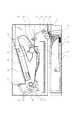
まず、本発明に係る画像形成装置(レーザービームプリンタ)の全体構成を図10を用いて説明する。ここでは、本画像形成装置の全体構成をシートの流れに沿って説明する。(First embodiment)
First, the overall configuration of an image forming apparatus (laser beam printer) according to the present invention will be described with reference to FIG. Here, the overall configuration of the image forming apparatus will be described along the flow of sheets.
画像形成装置の下側にはシート給送装置30が配置されている。本発明のシート収納部としての給紙カセット1に複数枚積載されたシートSは中板50によってその先端側を給紙ローラ3に向けて所定の加圧力で押し上げられ、高摩擦部材で形成された本発明のシート給送手段としての給紙ローラ3の表面と当接する。一方、給紙ローラ3は給紙時のみ図中反時計回りに回転するように制御され、当接して回転することによりシートSを摩擦力によって給送する。分離パッド2は給紙ローラ3へ向けてばね20によって付勢され、給紙ローラ3との間でシート束を捌き、最上部の一枚のシート以外を画像形成装置本体内へ給送させないよう働いている。 A
シート給送装置30により給送されたシートは搬送ローラ対4、5によって感光ドラム7と転写ローラ6の間のトナー像転写部8へと送られる。感光ドラム7は時計回りに回転しており帯電器9によって一様に帯電されたのち、画像信号に基づいてレーザースキャナー22より発射された選択的なレーザー光によって露光され静電潜像が形成される。この静電潜像は現像器10によって顕像化(トナー像化)される。感光ドラム7上に形成されたトナー像は転写ローラ6によって電気的に引きつけられることによって、トナー像転写部8を通過するシートの印字面(上面)に順次転写され、画像が形成される。 The sheet fed by the
画像の形成されたシートは、定着装置15の加熱手段13とこれに圧接する加圧ローラ14とのニップへ導かれ、シートがニップを通過する過程でシート面に転写されたトナー像は加熱及び加圧されてシート面に定着される。定着装置15を通過したシートは分離ガイド17によって加圧ローラ14から分離され、排紙ローラ対18、19によって搬送されて、排紙トレイ21上へ排出される。 The sheet on which the image has been formed is guided to the nip between the
図1〜図3を用いて本発明の第1実施の形態の構成について説明する。 The configuration of the first embodiment of the present invention will be described with reference to FIGS.
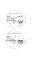
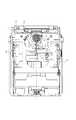
図1は本発明の第1実施の形態における断面図、図2はシート幅規制板をロックさせる部分の機構を表す詳細断面図、図3はシート幅規制板をロックさせるための拡大斜視図である。また、図6は給紙カセットを装置本体から取り出し時の動作を示す図、図7はシート幅規制板を大サイズ紙に合わせた状態を示す上面図、図8はシート幅規制板を小サイズ紙に合わせた状態を示す上面図、図9は中板ばねロック機構を表す斜視図である。 FIG. 1 is a cross-sectional view according to the first embodiment of the present invention, FIG. 2 is a detailed cross-sectional view showing a mechanism of a portion for locking the sheet width regulating plate, and FIG. 3 is an enlarged perspective view for locking the sheet width regulating plate. is there. 6 is a diagram showing the operation when the paper feeding cassette is taken out from the apparatus main body, FIG. 7 is a top view showing a state in which the sheet width regulating plate is aligned with the large size paper, and FIG. 8 is a diagram showing the small sheet width regulating plate. FIG. 9 is a perspective view showing an intermediate leaf spring locking mechanism. FIG.
まず、図6を用いて給紙カセット1を画像形成装置本体(以下装置本体という)に着脱する際の中板のロック動作に関して説明する。 First, with reference to FIG. 6, a description will be given of the locking operation of the middle plate when the paper feed cassette 1 is attached to and detached from the image forming apparatus main body (hereinafter referred to as the apparatus main body).
図6(a)は給紙カセット1が装置本体に装着された状態を表している。中板50は、給紙カセット1に軸1aを中心として回動自在に保持され、本発明の付勢手段としての3本の加圧ばね51a、51b(中央の加圧ばねを51aで両側の加圧ばねをそれぞれ51bで示す)によって装置本体に設けられている給紙ローラ3へ向けて付勢されている。中板50は、給紙カセット1の側面に設けられた開口部1aよりカセット両側面に突出する中板突出部50aを有している。給紙カセット1には、中板突出部50aに係合してロックするための中板ストッパ33が回動自在に支持されており、中板ストッパ33の爪部33aが中板突出部50aに係合することにより中板が押し下げられた位置でロックされる。これらの構成により本発明の中板ロック手段を構成する。 FIG. 6A shows a state in which the paper feed cassette 1 is mounted on the apparatus main body. The
また、装置本体には、中板突出部50aが摺接して中板を押し下げるための押し下げカム31と、中板ストッパ33を中板突出部50aに係合可能な位置と係合できない位置とに回動させる解除リブ32が配置されている。これらの構成により本発明の押し下げ手段を構成する。 Further, the apparatus main body has a push-
図6(a)では、中板ストッパ33は、装置本体に設けられた解除リブ32と当接し、中板ストッパ33の爪部33aが中板突出部50aの移動する軌跡から退避した状態となっている。 In FIG. 6A, the
この状態から給紙カセット1を図示右方向へ引き出すと、図6(b)に示すように中板突出部50aは装置本体に設けられた押し下げカム31と当接して案内されて下方へ押し下げられる。さらに給紙カセット1を引き出していくと、図6(c)に示すように中板ストッパ33と解除リブ32とが離間し、中板ストッパ33は自重、又は不図示のばねによる付勢によって時計回りに回動して所定の位置で停止する。さらに給紙カセット1を引き出すと、図6(d)に示すように、中板突出部50aと押し下げカム31との当接が解除され、中板50は加圧ばねによって上方に押し上げられ、ストッパ33と中板突出部50aとが当接したところで保持される。従ってユーザーがカセット1を引き出した時には、中板50は図6(d)の押し下げられた位置に保持される。 When the sheet feeding cassette 1 is pulled out from the state in the right direction in the figure, the
逆に、給紙カセット1を本体に装着する際には、図6(d)の中板50が保持された状態から、図6(c)に示すように押し下げカム31によって中板50は微小量押し下げられる。この状態において、中板ストッパ33は、中板50から力を受けていないため、小さな力で回動可能となっている。さらに給紙カセット1を押し込むと図6(b)に示すように中板ストッパ33は解除リブ32と当接し、爪部33aが中板突出部50aから退避した状態となり、中板50は押し下げカム31の傾斜面に沿って上昇する。そして、完全に給紙カセット1が装着された位置において、中板50は給紙ローラ3と当接した状態となる。 On the other hand, when the paper feed cassette 1 is mounted on the main body, the
なお、図6においては中板50上にシートは積載されていないが、シートが積載されていても全く同様の動作をし、給紙カセット1が装着されたときには最上のシートが給紙ローラ3に当接した状態にとなる。 Although no sheets are stacked on the
次に図1、図7乃至図9を用いて、シート幅規制板を移動させた際に給紙圧を変更する機構に関して説明する。 Next, a mechanism for changing the sheet feeding pressure when the sheet width regulating plate is moved will be described with reference to FIGS. 1 and 7 to 9.
通紙方向と直交する方向に移動可能に保持されたシート幅規制板66、67は共にピニオンギア71と係合しており、片方のシート規制板を移動させると他方も移動するよう構成されている。また、ばねロック部材62は給紙カセット1のシート幅規制板66、67と中板ばね51a(図1に図示)の間にある支点で保持され、回動可能であるように取り付けられ、引っ張りばね63により、引っ張られ、所定の位置で停止している。 The sheet
図7に示すシート幅規制板66、67は大サイズ紙(A4又はレターサイズ)に合わせた状態であり、シート幅規制板66の突き当て部66aは、ばねロック部材62の突き当て部62aと離間した位置にある。このときばねロック部材62は中板ばね51a及び、ばねキャップ61の軌跡から退避した位置にある。従って、不図示の中板は3本のばねによって、上方へ押し上げられ、後述する小サイズ紙設定よりも強い給紙圧を発生させる。 The sheet
一方、図8に示すようにシート幅規制板66、67を小サイズ紙(B5以下のサイズ)に合わせた場合、シート幅規制板66の突き当て部66aは、ばねロック部材62の突き当て面62aと当接し、ばねロック部材62は、ばねキャップ61へ向けて回動する(図7のC方向)。回動したばねロック部材62のストッパ部62aは、ばねキャップ61に設けられた段差部61aに入り込む。従って、中央の中板ばね51aは圧縮状態でロックされ、中板50は、左右の2本のばね51bによって上方へ押し上げられ、大サイズ紙のときより低い給紙圧を発生させる。なお、シート幅規制板66、67を再び広げると、引っ張りばね63によりばねロック部材62が図8のD方向に回動してロック部材62がばねキャップ61から離間して図7の状態となり、加圧ばね52aが中板を付勢する。 On the other hand, as shown in FIG. 8, when the sheet
前述したように給紙カセット1を装置本体から引き出した際には、中板50は押し下げられた位置で保持されている。この状態においてシート幅規制板66、67を操作することで確実に加圧ばね51aのロックとロック解除を行なうことができる。また、この状態においてばねキャップ61とばねロック部材62とは非接触状態を保っており、且つ、ばねロック部材62は、回転動作するため摺動抵抗が小さいため、ばねロック部材62の移動は小さい力で行なうことができため、シート幅規制板66、67の操作を妨げる方向に働く力を極めて小さくすることができる。 As described above, when the paper feed cassette 1 is pulled out from the apparatus main body, the
シート幅規制板66、67と係合しているピニオンギア71は、図3に示すように、その下部にピニオンギア71の歯先円よりも大きい円を外接円とする正多角形(本実施の形態では正八角形射)のフランジ71aを有し、かつピニオン軸73上を上下方向に移動可能で、ピニオンベース74を介し、加圧ばね72によって、常時、上方向に押し付けられている。ピニオンギア71が取り付くカセットフレーム側の形状は、筒形状であり、ピニオンギア71のフランジ部71aが嵌合する嵌合溝1aは、ピニオンギア71のフランジ部と同じ角数の正多角形形状であり、その一辺の長さは、両者が嵌合した時にピニオンギア71が回転しないような寸法関係に設定されている。 As shown in FIG. 3, the
この構成により、ピニオンギア71のフランジ部71aが嵌合溝1aに嵌合すると、ピニオンギア71は回転が規制されるため、シート幅規制板66、67がシート幅方向へ移動できずロック状態となる。 With this configuration, when the
中板50のシートセット面とは裏面側に中板カム70が配置されており、中板50が押し下げられたときにピニオンギア71に当接して押し下げることができる。 An
次に、シート幅規制板66、67をロックさせる機構について図1〜図3を用いて説明する。 Next, a mechanism for locking the sheet
給紙カセット1が、装置本体から取り外され、中板50が、図6(d)のように中板ストッパ33で保持状態にある時、中板カム70は、ピニオンギア71の上部を下側に押し込む。押し込まれたピニオンギア71は、図2(a)の状態から図2(b)の状態に変位する。このとき、図2(a)にある時のピニオンギア71のフランジ部71aは、ピニオンギア71が取り付けられている給紙カセット筒状部にあるフランジ部71aと同一角数を有した正多角形形状の嵌合溝1aから外れた状態になり、シート幅規制板のロックが解除され、シート幅規制板66、67をシート幅方向に操作することが可能になる。なお、正多角形の嵌合溝1aの一辺の長さは、ピニオンギア71のフランジ71aが嵌合した時に回転できない様に設定してある。 When the sheet feeding cassette 1 is removed from the apparatus main body and the
一方、中板50が、中板ストッパ33により保持されていない時、中板50は、図1(a)或いは、図2(a)にあるように、中板ばね51の圧により、上方向に回動(反時計方向)する。このとき、中板50に配設された中板カム70も回動する為、ピニオンギア71から離間する。ピニオンギア71は、上下方向に移動可能であり、ピニオンベース74を介して加圧ばね72により、常時上方向に加圧されているため、歯先円直径よりも大きい外接円に内接するピニオンフランジ71aの上面部が、給紙カセット1の正多角形の嵌合溝1aの上面部に突き当たるまで押し上げられる。この時、ピニオンフランジ71aと嵌合溝1aとが嵌合して、ピニオンギア71が回転できない状態にあるため、シート幅規制板66、67をロックしている状態になっている。 On the other hand, when the
このように、中板50のロックが解除されている状態では、シート幅規制板66、67がロックされ、シート幅規制板66、67をシート幅方向に操作することが不可能となり、中板50がロックされている状態では、シート幅規制板66、67のロックが解除され、シート幅規制板66、67をシート幅方向に操作することが可能になる。 As described above, in the state where the lock of the
(第2の実施の形態)
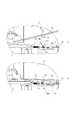
図4、図5を用いて本発明の第2実施の形態に係るシート給送装置の構成を説明する。図4は、第2の実施の形態における上面図、図5は、第2の実施の形態の要部詳細を表す断面図である。(Second Embodiment)
The configuration of the sheet feeding apparatus according to the second embodiment of the present invention will be described with reference to FIGS. FIG. 4 is a top view of the second embodiment, and FIG. 5 is a cross-sectional view showing details of a main part of the second embodiment.
給紙カセット1を装置本体から引き出す動作に関しては、第2実施の形態と同様であるためここでは説明を省略する。 Since the operation of pulling out the paper feed cassette 1 from the apparatus main body is the same as that in the second embodiment, the description thereof is omitted here.
シート幅規制板66、67をロックさせる手段について、図4乃至図6を用いて説明する。 Means for locking the sheet
幅規制ロック81が、突起1bによりシート給送方向に移動可能にカセットフレームに取り付けられている。この幅規制板81には、シート幅規制板66のラック部66bと噛み合うことが可能なラック部81aを有し、加圧ばね82によって、ラック部81aがラック66bと噛み合うように図中の矢印F方向に加圧されている。 A
給紙カセット1が、図6にあるように、シート給送装置から取り外され、中板50が、図6(d)ように中板ストッパ33で保持状態に移行する時、中板50に設けられている中板カム80の斜面80aは、幅規制ロック81の斜面81bと接しながら下がり、幅規制ロック81は、図5(b)にあるように矢印G方向に移動する。中板カム80の斜面80aと幅規制ロック81の斜面81bの斜面との関係は、幅規制ロック80が、図4に位置にあるように、幅規制ロック81のラック部81aが、シート幅規制板66のラック部66bとの噛み合いが解除できる位置まで離間できるように設定されているため、シート幅規制板66、67のロックが解除される。 When the sheet feeding cassette 1 is removed from the sheet feeding apparatus as shown in FIG. 6 and the
一方、中板50が、中板ストッパ33により保持されていない時、中板50は、図5(a)にあるように、中板ばね51a、51bの圧により、上方向に回動(反時計方向)する。このとき、中板50に配設された中板カム80も回動し、幅規制ロック81から離間するため、加圧ばね82によって、幅規制ロック81は、シート幅規制板66方向に押し付けられ、幅規制ロック81のラック部81aとシート幅規制66のラック部66bとが噛み合い、シート幅規制板66、67のシート幅方向の動きをロックさせる。 On the other hand, when the
このように、中板50のロックが解除されている状態では、シート幅規制板66、67がロックされ、シート幅規制板66、67をシート幅方向に操作することが不可能となり、中板50がロックされている状態では、シート幅規制板66、67のロックが解除され、シート幅規制板66、67をシート幅方向に操作することが可能になる。 As described above, in the state where the lock of the
1 給紙カセット
3 給紙ローラ
31 押し下げカム
32 解除リブ
33 中板ストッパ
50 中板
51 中板ばね
61 ばねキャップ
62 ばねロック部材
63 引っ張りばね
66 シート幅規制板
67 シート幅規制板
70、80 中板カム
71 ピニオンギア
72、82 加圧ばねDESCRIPTION OF SYMBOLS 1 Paper feed cassette 3
Claims (7)
Translated fromJapanese前記シート収納部に設けられ、シートが積載される上下方向に移動可能な中板と、
前記中板に積載されたシートのシート給送方向と直交する幅方向に移動可能に設けられ、積載されているシートの側端の位置を規制するシート幅規制手段と、
前記中板を前記画像形成装置本体に設けられたシート給送手段に向けて付勢する付勢手段と、
前記画像形成装置本体から引き出し動作時に、前記中板を付勢手段の付勢力に抗して下降させる押し下げ手段と、
前記押し下げ手段によって、押し下げられた前記中板を下降状態でロックする中板ロック手段と、
前記中板ロック手段により前記中板をロックしているときには、前記シート幅規制手段をシート給送方向と直交する方向に移動可能とし、前記中板ロック手段により前記中板がロックされていないときには、前記シート幅規制板の動きを規制するロック機構と、
を有することを特徴とするシート給送装置。A sheet storage unit that is detachably attached to the image forming apparatus main body and stores sheets;
An intermediate plate provided in the sheet storage unit and movable in a vertical direction on which sheets are stacked;
A sheet width regulating means provided to be movable in a width direction orthogonal to the sheet feeding direction of the sheets stacked on the intermediate plate, and for regulating the position of the side edge of the stacked sheets;
A biasing unit that biases the intermediate plate toward a sheet feeding unit provided in the image forming apparatus main body;
A push-down means for lowering the intermediate plate against the urging force of the urging means at the time of a pulling operation from the image forming apparatus main body;
An intermediate plate locking means for locking the intermediate plate pushed down by the push-down means in a lowered state;
When the intermediate plate is locked by the intermediate plate locking means, the sheet width regulating means is movable in a direction orthogonal to the sheet feeding direction, and when the intermediate plate is not locked by the intermediate plate locking means. A lock mechanism for regulating the movement of the sheet width regulating plate;
A sheet feeding apparatus comprising:
前記シート給送装置により供給されるシートに画像を形成する画像形成部と、
を有することを特徴とするが像形成装置。The sheet feeding apparatus according to any one of claims 1 to 6,
An image forming unit that forms an image on a sheet supplied by the sheet feeding device;
An image forming apparatus.
Priority Applications (1)
| Application Number | Priority Date | Filing Date | Title |
|---|---|---|---|
| JP2004295825AJP2006103933A (en) | 2004-10-08 | 2004-10-08 | Sheet feeding apparatus and image forming apparatus |
Applications Claiming Priority (1)
| Application Number | Priority Date | Filing Date | Title |
|---|---|---|---|
| JP2004295825AJP2006103933A (en) | 2004-10-08 | 2004-10-08 | Sheet feeding apparatus and image forming apparatus |
Publications (1)
| Publication Number | Publication Date |
|---|---|
| JP2006103933Atrue JP2006103933A (en) | 2006-04-20 |
Family
ID=36374084
Family Applications (1)
| Application Number | Title | Priority Date | Filing Date |
|---|---|---|---|
| JP2004295825APendingJP2006103933A (en) | 2004-10-08 | 2004-10-08 | Sheet feeding apparatus and image forming apparatus |
Country Status (1)
| Country | Link |
|---|---|
| JP (1) | JP2006103933A (en) |
Cited By (5)
| Publication number | Priority date | Publication date | Assignee | Title |
|---|---|---|---|---|
| JP2008087900A (en)* | 2006-09-29 | 2008-04-17 | Canon Inc | Sheet feeding apparatus and image forming apparatus |
| JP2011116505A (en)* | 2009-12-03 | 2011-06-16 | Canon Inc | Sheet member feeding device and image forming apparatus |
| JP2017200844A (en)* | 2016-05-02 | 2017-11-09 | コニカミノルタ株式会社 | Sheet material feeding device and image forming apparatus |
| JP2019147688A (en)* | 2018-02-28 | 2019-09-05 | セイコーエプソン株式会社 | Recording device |
| JP2022019840A (en)* | 2018-02-28 | 2022-01-27 | セイコーエプソン株式会社 | Recording device |
- 2004
- 2004-10-08JPJP2004295825Apatent/JP2006103933A/enactivePending
Cited By (6)
| Publication number | Priority date | Publication date | Assignee | Title |
|---|---|---|---|---|
| JP2008087900A (en)* | 2006-09-29 | 2008-04-17 | Canon Inc | Sheet feeding apparatus and image forming apparatus |
| JP2011116505A (en)* | 2009-12-03 | 2011-06-16 | Canon Inc | Sheet member feeding device and image forming apparatus |
| JP2017200844A (en)* | 2016-05-02 | 2017-11-09 | コニカミノルタ株式会社 | Sheet material feeding device and image forming apparatus |
| JP2019147688A (en)* | 2018-02-28 | 2019-09-05 | セイコーエプソン株式会社 | Recording device |
| JP2022019840A (en)* | 2018-02-28 | 2022-01-27 | セイコーエプソン株式会社 | Recording device |
| JP7314984B2 (en) | 2018-02-28 | 2023-07-26 | セイコーエプソン株式会社 | recording device |
Similar Documents
| Publication | Publication Date | Title |
|---|---|---|
| KR101061297B1 (en) | Sheet feeding device and image forming device | |
| USRE44947E1 (en) | Sheet feeding device and image forming apparatus | |
| JP5058740B2 (en) | Sheet feeding apparatus and image forming apparatus | |
| JP5219720B2 (en) | Sheet feeding apparatus and image forming apparatus | |
| JPWO2014091616A1 (en) | Sheet stacking apparatus and image forming apparatus | |
| JP5634451B2 (en) | Image forming apparatus | |
| JP5641731B2 (en) | Sheet feeding apparatus and image forming apparatus | |
| EP3549777A1 (en) | Sheet loading device and image forming apparatus incorporating the sheet loading device | |
| JP6929703B2 (en) | Sheet loading device and image forming device | |
| US10865058B2 (en) | Sheet feeding device, image forming apparatus incorporating the sheet feeding device, and device attachment body of the sheet feeding device | |
| JP5871510B2 (en) | Sheet feeding apparatus and image forming apparatus | |
| US8746683B2 (en) | Sheet feeder and image forming apparatus | |
| JP5006670B2 (en) | Sheet feeding apparatus and image forming apparatus | |
| JP2006103933A (en) | Sheet feeding apparatus and image forming apparatus | |
| US11040842B2 (en) | Sheet supporting apparatus and image forming apparatus | |
| JP2009132469A (en) | Image recording medium feeder and image forming device | |
| JP4773984B2 (en) | Sheet feeding apparatus and image forming apparatus | |
| JP2016169064A (en) | Sheet loading device, sheet feeding device, and image formation apparatus | |
| JP2022075711A (en) | Image forming device | |
| JP4136781B2 (en) | Sheet storage device and image forming apparatus | |
| JP2005263450A (en) | Paper feed cassette | |
| JP2014105098A (en) | Sheet feeder and image formation apparatus | |
| JP5533514B2 (en) | Image forming apparatus | |
| JP2018030686A (en) | Sheet storage device and image formation device | |
| JP2006082960A (en) | Paper feeding device |
Legal Events
| Date | Code | Title | Description |
|---|---|---|---|
| A621 | Written request for application examination | Free format text:JAPANESE INTERMEDIATE CODE: A621 Effective date:20070802 | |
| A977 | Report on retrieval | Effective date:20090604 Free format text:JAPANESE INTERMEDIATE CODE: A971007 | |
| A131 | Notification of reasons for refusal | Free format text:JAPANESE INTERMEDIATE CODE: A131 Effective date:20090616 | |
| A521 | Written amendment | Free format text:JAPANESE INTERMEDIATE CODE: A523 Effective date:20090817 | |
| A02 | Decision of refusal | Effective date:20091124 Free format text:JAPANESE INTERMEDIATE CODE: A02 | |
| RD04 | Notification of resignation of power of attorney | Effective date:20100201 Free format text:JAPANESE INTERMEDIATE CODE: A7424 |