JP2006103216A - Image output apparatus, image output method, and recording medium - Google Patents
Image output apparatus, image output method, and recording mediumDownload PDFInfo
- Publication number
- JP2006103216A JP2006103216AJP2004294523AJP2004294523AJP2006103216AJP 2006103216 AJP2006103216 AJP 2006103216AJP 2004294523 AJP2004294523 AJP 2004294523AJP 2004294523 AJP2004294523 AJP 2004294523AJP 2006103216 AJP2006103216 AJP 2006103216A
- Authority
- JP
- Japan
- Prior art keywords
- color
- image output
- color conversion
- information
- obtaining
- Prior art date
- Legal status (The legal status is an assumption and is not a legal conclusion. Google has not performed a legal analysis and makes no representation as to the accuracy of the status listed.)
- Granted
Links
Images


Landscapes
- Facsimile Image Signal Circuits (AREA)
- Color Image Communication Systems (AREA)
- Ink Jet (AREA)
- Color, Gradation (AREA)
- Image Processing (AREA)
Abstract
Translated fromJapaneseDescription
Translated fromJapanese本発明は、入力されたカラー画像信号に最適な色変換を行ない出力する画像出力装置及び色変換の制御方法に関する。 The present invention relates to an image output apparatus that performs optimal color conversion on an input color image signal and outputs the same, and a color conversion control method.
従来、カラープリンタなどのカラー画像出力装置において、色信号変換に数多くの技術が提案されている。その一つとして、入力sRGB色空間から出力CMYK色空間への色変換がある。 Conventionally, many techniques have been proposed for color signal conversion in color image output devices such as color printers. One example is color conversion from an input sRGB color space to an output CMYK color space.
一方、カラープリンタに使用される色材には種々のものが存在し、それらの物理特性は色材毎に異なっている。電子写真で使用される代表的な色材はトナーであるが、製品やメーカ、及びロット番号毎に分光特性等の物理特性が大きく異なっている。 On the other hand, there are various color materials used in color printers, and their physical characteristics differ from color material to color material. A typical color material used in electrophotography is toner, but physical characteristics such as spectral characteristics are greatly different for each product, manufacturer, and lot number.
通常、カラープリンタにおいては、色変換テーブルの最適化を行うために膨大な数のカラーパッチを出力し、それらの分光反射率を測定し、分光反射率データから色変換テーブルを算出するのが一般的であった。 Usually, in color printers, in order to optimize the color conversion table, it is common to output a large number of color patches, measure their spectral reflectance, and calculate the color conversion table from the spectral reflectance data. It was the target.
しかしながら、上記の作業は大変な手間を伴うものであり、またカラープリンタの経時変動や面内変動があるため正確な色のカラーパッチを出力できないという問題点があった。また、トナーの分光特性はロット毎にも異なるため、使用しているトナーに対して色変換テーブルが最適化されておらず、適正な色が得られていなかった。 However, the above work is very troublesome, and there is a problem that a color patch of an accurate color cannot be output because there is a change with time and an in-plane change of the color printer. Further, since the spectral characteristics of the toner differ from lot to lot, the color conversion table is not optimized for the toner used, and an appropriate color cannot be obtained.
例えば、カラープリント出力したカラーパッチの分光反射率情報から、色変換パラメータを算出するカラーマスキングパラメータ決定装置(例えば、特許文献1を参照)、色変換パラメータの算出方法(カラーマネージメントモジュール)、及びデバイス情報をネットワークサーバより受け取りカラーマッチングを行なうネットワークサーバ及び画像処理方法(例えば、特許文献2を参照)などがある。 For example, a color masking parameter determination device (see, for example, Patent Document 1) that calculates a color conversion parameter from spectral reflectance information of a color patch that has been output by color printing, a color conversion parameter calculation method (color management module), and a device There are a network server that receives information from a network server and performs color matching, an image processing method (see, for example, Patent Document 2), and the like.
しかしながら、上記特許文献1に開示された装置では、色変換パラメータを得るために実機でカラーパッチを出力しなくてはならず、大変な手間を伴う。またカラープリンタの経時変動や面内変動があるため正確な色が出力できない場合がある。さらに実機がないとカラーパッチを作成できないため、開発段階では色変換パラメータの最適化を行なえないという問題点がある。 However, in the apparatus disclosed in
また、カラープリンタを使用する場合は一般的にドライバーソフトが必要である。ドライバーソフトはカラープリンタの購入時にCDで付属していたり、ネットワーク経由で最新版をダウンロードしたりして手に入れることができる。ここで、色変換パラメータもドライバーソフトに含まれていることが多い。つまり、ドライバーソフトに含まれている色変換パラメータはユーザが使用するカラープリンタの色材とは異なる分光特性を持つ色材情報に基づいて作成されていることが多いため、現在使っている色材に対して最適化されていない。 When using a color printer, driver software is generally required. You can get the driver software on the CD when you purchase the color printer, or you can download the latest version via the network. Here, the color conversion parameters are often included in the driver software. In other words, the color conversion parameters included in the driver software are often created based on color material information that has spectral characteristics different from the color material of the color printer used by the user. Not optimized for.
また、上記特許文献2に開示された装置では、色変換パラメータの算出方法、及びデバイス(色材)情報をネットワークサーバより受け取らねばならず、カラープリンタがネットワークに接続されている必要がある。 In the apparatus disclosed in
本発明は上記の課題に鑑みてなされたもので、
本発明の目的は、カラー画像出力装置で使用されている色材の物理特性を自動的に認識し、使用している色材の物理特性に応じて適切な色変換処理を行い、画像出力を行なう画像出力装置、画像出力方法および記録媒体を提供することにある。The present invention has been made in view of the above problems,
An object of the present invention is to automatically recognize physical characteristics of a color material used in a color image output apparatus, perform an appropriate color conversion process according to the physical characteristics of the color material being used, and output an image. An image output apparatus, an image output method, and a recording medium are provided.
すなわち、
請求項1、11では、使用している色材に関わる物理特性情報を得て、色変換を行う装置を提供することを目的としている。That is,
It is an object of the present invention to provide an apparatus that obtains physical characteristic information relating to a color material being used and performs color conversion.
請求項2では、色材の組み合わせに応じた最適な色再現範囲を得ることが可能な装置を提供することを目的としている。 It is an object of the present invention to provide an apparatus capable of obtaining an optimum color reproduction range corresponding to a combination of color materials.
請求項3では、使用する色材が画像出力装置(または機器)に着脱可能である場合に、色材の物理特性を適切に得ることが可能な装置を提供することを目的としている。 It is an object of the present invention to provide an apparatus that can appropriately obtain physical properties of a color material when the color material to be used is detachable from an image output apparatus (or device).
請求項4では、使用する色材が画像出力装置に着脱不可能であっても、色材の物理特性を適切に得ることが可能な装置を提供することを目的としている。 It is an object of the present invention to provide an apparatus that can appropriately obtain physical properties of a color material even if the color material to be used is not detachable from the image output apparatus.
請求項5では、色変換パラメータを得るための式、もしくはプログラムの取得が可能な装置を提供することを目的としている。 An object of the present invention is to provide an apparatus capable of acquiring an expression for obtaining a color conversion parameter or a program.
請求項6では、色材に関わる物理特性情報から色変換パラメータを得るための方法を提供することを目的としている。 The object of the present invention is to provide a method for obtaining a color conversion parameter from physical property information relating to a color material.
請求項7では、ネットワーク上のサーバから色変換パラメ−タに関する情報の取得が可能な装置を提供することを目的としている。 It is an object of the present invention to provide an apparatus capable of acquiring information relating to color conversion parameters from a server on a network.
請求項8では、紙などの記録媒体に関わる物理特性情報を用いて色変換を行なう方法を提供することを目的としている。 An object of the present invention is to provide a method for performing color conversion using physical characteristic information relating to a recording medium such as paper.
請求項9では、適切なタイミングで色変換パラメータの取得、もしくは更新が可能な装置を提供することを目的としている。 It is an object of the present invention to provide an apparatus capable of acquiring or updating color conversion parameters at an appropriate timing.
請求項10では、使用している色材に関わる物理特性情報を得て、色変換を行なう方法を提供することを目的としている。 It is an object of the present invention to provide a method for performing color conversion by obtaining physical characteristic information relating to a color material being used.
本発明は、画像出力機器であって、該出力機器にて使用される記憶媒体付きの色材格納ユニットから色材に関わる物理特性もしくは、物理特性を得るための情報を取得する物理特性情報取得手段と、色変換パラメータを得る色変換パラメータ取得手段とを具備することを最も主要な特徴とする。 The present invention is an image output device, and obtains physical property information related to a color material or information for obtaining the physical property from a color material storage unit with a storage medium used in the output device. And a color conversion parameter acquisition means for obtaining a color conversion parameter.
請求項1の画像出力装置(または機器)においては、使用している色材固有の情報を得て、色変換を行うようにしているため、色材の特性に応じた高精度な色変換処理を行なうことができる。 In the image output device (or device) according to
請求項2の画像出力装置においては、色材個々の物理特性情報、もしくは物理特性に関わる情報のいづれかを使用して色変換を行なうため、色材の特性に応じた高精度な色変換処理を行なうことができる。 In the image output apparatus according to
請求項3の画像出力装置においては、使用する色材のカートリッジ付随のRFIDに書きこんである色材情報を直接読み取るようにしているため、より正確な情報の入手を行なうことができる。 In the image output apparatus according to the third aspect, since the color material information written in the RFID attached to the cartridge of the color material to be used is directly read, more accurate information can be obtained.
請求項4の画像出力装置においては、色材をカートリッジに補充して使用する場合でも色材の入っていた容器に付随のRFIDによる近接無線交信が可能であるため、正確に色材情報の入手を行なうことが可能である。 According to the fourth aspect of the present invention, even when the color material is replenished in the cartridge and used, the container in which the color material is contained can perform close proximity wireless communication using the attached RFID. Can be performed.
請求項5の画像出力装置においては、色変換パラメータを取得するための式、もしくはプログラムをダウンロードして取得するようにしているため、色変換パラメータの算出方式が変わっても容易に対応することができる。 In the image output apparatus according to the fifth aspect, since an expression for acquiring the color conversion parameter or a program is downloaded and acquired, it is possible to easily cope with a change in the calculation method of the color conversion parameter. it can.
請求項6の画像出力装置においては、色材の物理特性情報から色変換パラメータを得るようにしているため、色材の特性に応じた高精度な色変換処理を行なうことができる。 In the image output apparatus according to the sixth aspect, since the color conversion parameter is obtained from the physical property information of the color material, it is possible to perform a highly accurate color conversion process according to the property of the color material.
請求項7の画像出力装置においては、物理特性もしくは、物理特性を得るための情報をネットワーク上のサーバに送り、サーバから色変換パラメータに関する情報をダウンロードして取得するようにしているため、画像出力装置における計算負荷を軽減することができる。 In the image output apparatus according to claim 7, physical characteristics or information for obtaining physical characteristics is sent to a server on the network, and information regarding color conversion parameters is downloaded and acquired from the server. Calculation load on the apparatus can be reduced.
請求項8の画像出力装置においては、記録媒体に関わる物理特性情報を用いて色変換を行なうようにしているため、記録媒体の特性に応じた高精度な色変換処理を行なうことができる。 In the image output apparatus according to the eighth aspect, since color conversion is performed using physical characteristic information relating to the recording medium, it is possible to perform highly accurate color conversion processing according to the characteristics of the recording medium.
請求項9の画像出力装置においては、プログラムを取得した時、もしくは、色材の少なくともひとつが交換されたタイミングで色変換パラメータの取得、もしくは更新がおこなわれるため、常に最適な色変換パラメータを使用することができる。 In the image output apparatus according to claim 9, since the color conversion parameter is acquired or updated when the program is acquired or at least when one of the color materials is replaced, the optimum color conversion parameter is always used. can do.
請求項10の画像出力方法においては、使用している色材固有の情報を得て、色変換を行うようにしているため、色材の特性に応じた高精度な色変換処理を行なうことができる。 In the image output method according to the tenth aspect, since information specific to the color material being used is obtained and color conversion is performed, high-accuracy color conversion processing according to the characteristics of the color material can be performed. it can.
請求項11の画像出力装置にて使用される色変換を行なうためのプログラムを記録した記憶媒体においては、画像出力装置において使用される色材固有の情報を得て、色変換を行うようにしているため、色材の特性に応じた高精度な色変換処理を行なうことができる。 In a storage medium storing a program for performing color conversion used in the image output apparatus according to
以下、発明の実施の形態について図面により詳細に説明する。 Hereinafter, embodiments of the present invention will be described in detail with reference to the drawings.
実施例1(プリンタがネットワークにつながっていない場合)
全体システムの構成・動作
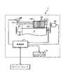
図1は、本実施形態に係るプリンタ1の概略機能構成を説明するためのブロック図である。なお、プリンタ1は、インクジェット方式のカラープリンタを図示しているが、電子写真方式など他の方式を用いたカラープリンタであっても構わない。Example 1 (when the printer is not connected to the network)
Configuration and Operation of Overall System FIG. 1 is a block diagram for explaining a schematic functional configuration of a
図1に示すように、プリンタ1は、大きく分けて、制御装置11と印刷機構部12とから構成されている。制御装置11は、インターフェース13、信号処理部14、駆動回路部15などからなり、外部のホストコンピュータから送信されるプリントジョブデータに基づいて、印刷機構部12を制御しながら印刷用紙に対する印刷処理を実行する。 As shown in FIG. 1, the
インターフェース13は、ケーブルを介して接続されたホストコンピュータとの間で通信を行なうための機能を提供している。ホストコンピュータとの接続は、シリアルまたはパラレル接続であるとする。プリンタ1は、典型的には、インターフェース13を介してホストコンピュータからプリントジョブデータを受信して、印刷処理を実行するが、プリンタ1本体に装着されたメモリカードから印刷対象データを読み出して、印刷処理を実行してもよい。 The
信号処理部14は、相互に内部バスで接続されたCPU141、ROM142、RAM143等から構成されている。CPU141は、主記憶装置として機能するRAM143を用いながらROM142に記憶された各種の制御プログラムを実行し、プリンタ1を統括的に制御する。例えば、出力イメージ生成機能、印刷制御機能、ユーザインターフェース機能などが制御プログラムによって実現される。出力イメージ生成機能は、インターフェース13を介して受信したプリントジョブデータを解釈しながら、後述の画像処理を行ない印刷機構部に送出可能なイメージデータを生成する機能である。生成されたイメージデータは、RAM143の一部として構成されるイメージバッファメモリに書き込まれ、一時的に保持される。印刷制御機能は、イメージバッファメモリに書き込まれたイメージデータに基づき駆動回路部15を制御する機能である。 The
駆動回路部15は、印刷機構部12の印刷ヘッド121、キャリッジ122、搬送ローラ123をそれぞれ制御するための制御回路を搭載しており、信号処理部からの制御コマンドにより動作する。また、ユーザインターフェース機能は、ユーザインターフェース部16によりインタラクティブな操作環境をユーザに提供する機能である。ユーザインターフェース部16は、典型的には各種のボタン、LED表示ランプおよび液晶パネル等から構成される。 The
印刷機構部12は、印刷実行時に動作するメカニカルな部材を中心に構成されている。具体的には、印刷機構部12は、印刷用紙に対して記録を行なう印刷ヘッド121、この印刷ヘッド121を搭載するキャリッジ122、印刷用紙を搬送する搬送ローラ123等から構成される。駆動回路部15は、これら印刷機構部12のメカニカルな部材を、生成されたイメージデータに基づいてそれぞれ駆動制御するためのものであり、印刷機構部12の構成に応じて、印刷ヘッド駆動回路151、キャリッジ駆動回路152、搬送ローラ駆動回路153等から構成される。 The
図2は、本実施形態に係る印刷機構部12の概略構成を示す図である。印刷ヘッド121は、イエロー(Y)、マゼンタ(M)、シアン(C)、ブラック(K)色毎に図3に示す主走査方向に配列された複数の記録素子を備えている。この印刷ヘッド121を搭載したキャリッジ122は、2つのプーリによって張設された無端ベルト21に取り付けられており、キャリッジモータ22が回転駆動されることで、キャリッジ軸23に沿ってその軸方向(主走査方向)に往復移動する。また、印刷用紙Pは、搬送モータ24によって回転駆動される搬送ローラ123により図3に示す副走査方向に搬送される。 FIG. 2 is a diagram illustrating a schematic configuration of the
キャリッジ122にはカートリッジスロットが設けられている。各色ごとにインク液を収容したインクカートリッジ25は、対応するカートリッジスロットに着脱自在にセットされ、印刷ヘッド121の記録素子にインク液を供給する。 The
プリンタ1は、インクカートリッジ25として、イエロー(Y)、マゼンタ(M)、シアン(C)、ブラック(K)が自由に着脱可能であるものとする。また、キャリッジ122のカートリッジスロットは4つ設けられており、同時装着可能なインクカートリッジは4種類のみとする。 In the
このように構成される印刷機構部12において、印刷ヘッド121は、搬送モータ24の回転動作に合わせて副走査方向に搬送される印刷用紙P上を、キャリッジモータ22の回転動作に合わせて主走査方向に往復移動しながら、印刷ヘッド駆動回路151により駆動される記録素子からインク滴を吐出して、これを印刷用紙Pに付着させてドットを形成し、印刷用紙P上に画像を再現することができる。
(RFIDの説明)
また、インクカートリッジ25は、図4に示す書き換え可能な記録媒体を備えている。記録媒体には、一般にRFID(Radio Frequency Identification)と称せられる素子を、物理的な接触により取り付けられた形態を有する。RFID素子に対する呼び名として、無線タグ、ICタグ、無線ICタグ、近接無線交信素子などもある。In the
(Description of RFID)
The
このRFIDは、所定のカートリッジ情報を記憶している。所定のカートリッジ情報とは、例えば収容しているインク(インクカートリッジ)の種別情報等である。このようなインクカートリッジ25がカートリッジスロットにセットされると、インクカートリッジ25のRFIDは、信号処理部14と接続された状態になり、信号処理部14は、RFIDにアクセスして、必要な情報を読み出すことができる。 This RFID stores predetermined cartridge information. The predetermined cartridge information is, for example, type information of the ink (ink cartridge) that is stored. When such an
本実施例ではRFIDに記録される情報が色材の物理特性情報そのものである場合について述べる。ここで色材の物理特性とは分光反射率や分光透過率などの分光特性、又は色材含有率やインク量、インク濃度、トナー厚さ、重量、光沢度などの材質特性、又は色度などの色特性であり、色数分の情報を組み合わせることによって画像出力機器の色再現範囲(ガマット)を算出できるものである。 In this embodiment, the case where the information recorded in the RFID is the physical property information itself of the color material will be described. Here, the physical characteristics of the color material include spectral characteristics such as spectral reflectance and spectral transmittance, or material characteristics such as color material content rate, ink amount, ink concentration, toner thickness, weight, and glossiness, or chromaticity. The color reproduction range (gamut) of the image output device can be calculated by combining information for the number of colors.
また、RFIDは近接無線交信が可能であるため、別容器に入っている色材のみをカートリッジに入れ替えて使用する場合、別容器に付随のRFIDに記憶されている色材の物理特性情報を近接無線交信によってプリンタに認識させることも可能である。
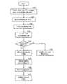
(色変換パラメータを得る流れ)
次に、本実施形態における色変換パラメータの取得処理について説明する。図5は、本実施形態に係る色変換パラメータの取得処理の流れを説明するためのフローチャートである。ここで、本実施例において、色変換パラメータを取得するための方法は信号処理部14が持っており、色変換パラメータが更新されるのは、カートリッジの入れ替え、もしくはインクの補充等で色材の物理特性情報が新しくなる時であるとする。In addition, since RFID can perform close proximity wireless communication, when only the color material contained in a separate container is used by replacing it with a cartridge, the physical property information of the color material stored in the RFID attached to the separate container is close. It is also possible to make the printer recognize by wireless communication.
(Flow for obtaining color conversion parameters)
Next, color conversion parameter acquisition processing according to the present embodiment will be described. FIG. 5 is a flowchart for explaining the flow of the color conversion parameter acquisition process according to this embodiment. In this embodiment, the
また、本実施例では、カートリッジのRFIDにはインクを紙に印刷した場合の分光透過率が記述されている。信号処理部14は、S100においてRFIDより各色の分光透過率を受け取り、S101において、紙の分光反射率を受け取る。ここで、紙の分光反射率は画像出力機器があらかじめ持っていても構わないし、紙の包装紙に情報を記憶させたRFIDを埋め込み、そこから呼びだすなどしても構わない。 In the present embodiment, the RFID of the cartridge describes the spectral transmittance when ink is printed on paper. The
次にS102において、イエロー(Y)、マゼンタ(M)、シアン(C)である1次色の分光透過率、及び紙の分光反射率を用いて、1,2,3次色ベタの分光反射率を予測する。ベタ分光反射率の予測には、例えばクベルカ-ムンク理論(P.Kubelka & F.Munk:"Ein Beitrag zur Optik der Ferbanstriche",Z.tech Physik,12,p.593(1931))や、ウィリアムズ-クラッパ理論(F.C.Williams and Clapper:"Multiple internal reflections in photographic color prints",J.Opt.Soc.Am.,43,p.595(1953))の方式が提案されているが他の方式を用いても構わない。 Next, in step S102, the spectral reflection of the primary color of 1, 2 and 3 is obtained using the spectral transmittance of the primary colors of yellow (Y), magenta (M), and cyan (C) and the spectral reflectance of the paper. Predict rates. For example, Kuberka-Munk theory (P. Kubelka & F. Munk: "Ein Beitrag zur Optik der Ferbanstriche", Z.tech Physik, 12, p.593 (1931)) and Williams- Clapper theory (FCWilliams and Clapper: "Multiple internal reflections in photographic color prints", J. Opt. Soc. Am., 43, p. 595 (1953)) has been proposed, but other methods are used. It doesn't matter.
ここで、クベルカ-ムンク理論は、色材の光吸収率と光拡散率、及び紙の反射率から微分方程式を構築して入射光に対する反射率を算出する手法である。また、ウィリアムズ-クラッパ理論は、紙の上に色材がのっている場合に、入射した光が色材層内部で多重反射する様子を光線追跡して反射率を算出する手法である。 Here, the Kubelka-Munk theory is a method of calculating a reflectance with respect to incident light by constructing a differential equation from the light absorptance and light diffusivity of a color material and the reflectance of paper. The Williams-Clapper theory is a method of calculating the reflectivity by tracing the state in which incident light is multiply reflected inside the color material layer when a color material is on the paper.
なお、1次色は印刷で言うとインクそのものの色、つまりCMYである。ちなみに、2次色は1次色のうちの2つの色を用いて作られる色で、RGBを2次色という場合もある。3次色も同様で3色を用いて作られる。Kを3次色と呼ぶ場合もある。 In terms of printing, the primary color is the color of the ink itself, that is, CMY. Incidentally, the secondary color is a color created using two of the primary colors, and RGB may be referred to as a secondary color. Tertiary colors are similar and are made using three colors. K may be called a tertiary color.
次に、S103において、信号処理部14にあらかじめ記憶させている中間調処理方式を用いてハーフトーンの分光反射率を予測する。ハーフトーン分光反射率の予測には、例えばクラッパ-ユール理論(F.R.clapper and J.A.C.Yule:"The Effect of Multiple Internal Reflections on the Densities of Half-tone Prints on Paper",J.Opt.Soc.Am.,43,p.600(1953))の方式が提案されているが他の方式を用いても構わない。クラッパ-ユール理論は色材の透過率、及び面積率からハーフトーンの分光反射率を予測する。ウィリアムズ-クラッパ理論をベースにして、紙内部での多重反射を考慮している。 Next, in S103, the halftone spectral reflectance is predicted using a halftone processing method stored in the
もしくは、中間処理方式の計算は複雑であり、ハーフトーンの分光反射率予測は困難であるため、計算時間を短縮するために中間調処理シミュレーション後の分光反射率をあらかじめROM142等に記憶しておき、分光反射率を予測する方式をとっても構わない。 Alternatively, since the calculation of the intermediate processing method is complicated and it is difficult to predict the halftone spectral reflectance, the spectral reflectance after the halftone processing simulation is stored in advance in the
次にS104において、算出されたベタ、及びハーフトーンの分光反射率の比較更新処理を行う。プリンタ1において、ROM142等に分光反射率が記録されていない場合、算出された分光反射率はROM142に記録される。一方、すでにROM142に分光反射率が記録されている場合はその分光反射率とS103にて算出された分光反射率の比較を行う。例えば両者の2乗誤差の最大値や平均値を比較しそれがある閾値以下の場合はS105以下の処理、即ち色変換パラメータの算出、及び更新を行わないことで(S108)、無駄な処理を減らすことができる。分光反射率を比較した結果、両者の誤差が閾値以上の場合はS105以下の処理を行う。また、ROM142にはS103にて算出した分光反射率を書き込んで情報の更新を行う。ここで、閾値は最大誤差が5%、平均誤差が3%程度であるのが理想である。 In step S104, the calculated solid and halftone spectral reflectances are compared and updated. In the
次にS105において、信号処理部14にあらかじめ記憶させている等色関数、D50光源の分光スペクトル、及びS103にて算出したベタ、及びハーフトーンの分光反射率を用いて三刺激値を算出し、次にL*a*b*などの均等色空間に変換し、次に画像出力機器のガマットを算出する。また、同時にL*a*b*信号とそれを紙上に再現するプリンタ色信号(C,M,Y,K)の組み合わせを関係付ける式も算出しておく。 Next, in S105, a tristimulus value is calculated using the color matching function stored in advance in the
次にS106において、プリントジョブデータの色信号(R,G,B)のL*a*b*均等色空間におけるガマットを上記画像出力機器のガマットへ圧縮する。 In step S106, the gamut of the color signals (R, G, B) of the print job data in the L * a * b * uniform color space is compressed into the gamut of the image output device.
以上の処理により、プリントジョブデータの色信号(R,G,B)をガマット圧縮後のL*a*b*信号に変換し、さらにプリンタ1が出力可能なプリンタ色信号(C,M,Y,K)へ変換するための色変換パラメータを得ることができる(S107)。 Through the above processing, the color signals (R, G, B) of the print job data are converted into L * a * b * signals after gamut compression, and printer color signals (C, M, Y that can be output by the printer 1). , K) can be obtained (S107).
図6は、図1のCPU141における色変換処理を表すブロック図である。プリントジョブデータの色信号(R,G,B)901は、均等色色空間処理部902においてL*a*b*信号903に変換され、さらにガマット処理部904においてガマット圧縮後のL*a*b*信号である、L*’a*’b*’信号905に変換される。また、RAM907にはL*’a*’b*’信号とプリンタ色信号(C,M,Y,K)との関係が記録されており、この出力デバイスプロファイルを用いて、色変換処理部906において、L*’a*’b*’信号がプリンタ1が出力可能なプリンタ色信号(C,M,Y,K)908へと変換される。 FIG. 6 is a block diagram showing color conversion processing in the
もしくは、一般的な色変換は色変換テーブルを用いて行なわれる。色変換テーブルは、入力データと印刷用紙上に色再現された場合の望ましいプリンタ出力データとを対応づけた多次元ルックアップテーブルであり、色補間パラメータを使用してジョブデータの色信号(R,G,B)をプリンタ1が出力可能なプリンタ色信号(C,M,Y,K)に変換する。色変換方法としては、公知のメモリマップ補間法を用いた色変換処理装置を使用することができる。メモリマップ補間法では色変換プロファイルとして設定した多次元ルックアップテーブルを使用する。いづれにせよ、色変換パラメータもしくは色変換テーブルは紙種や後述する出力モード、中間調処理等に応じて算出され、典型的にはプリンタ1のROM142等に記憶されている。 Alternatively, general color conversion is performed using a color conversion table. The color conversion table is a multi-dimensional lookup table in which input data and desired printer output data when color reproduction is performed on a printing paper are associated with each other, and color signals (R, R) of job data using color interpolation parameters. G, B) are converted into printer color signals (C, M, Y, K) that can be output by the
図7は、図1のCPU141における色変換処理を表すブロック図である。ここでの色変換処理は色変換テーブルを用いて行われる。色変換テーブルファイルには各RGBデータに対応するCMYKデータが記憶されている。よって、プリントジョブデータの色信号(R,G,B)101は、色変換処理部102において、104の色変換テーブルを用いて、プリンタ色信号(C,M,Y,K)103に直接変換される。
(印刷動作の流れ)
次に、本実施形態における印刷システムの処理動作について説明する。図8は、本実施形態に係るプリンタ1の印刷時における処理の流れを説明するためのフローチャートである。プリンタ1が印刷要求を受け付けると、プリントジョブデータが信号処理部14に送られて、図8のフローチャートの手順に従って出力イメージに変換される。印刷要求は、例えばホストコンピュータからプリントジョブデータの形態で受け付ける。FIG. 7 is a block diagram showing color conversion processing in the
(Flow of printing operation)
Next, the processing operation of the printing system in this embodiment will be described. FIG. 8 is a flowchart for explaining the flow of processing during printing by the
プリントジョブデータは、典型的には図8に示すようにヘッダ部に画像データの色空間属性や大きさ、位置などの各種属性情報が書き込まれており、その後、画像データの内容が続くものとして説明する。ここで、プリントジョブデータの色空間属性としてはホストコンピュータ上のアプリケーションで作成されたRGB形式のデータである。 In print job data, typically, as shown in FIG. 8, various attribute information such as color space attribute, size, and position of image data is written in the header portion, and then the content of the image data continues. explain. Here, the color space attribute of the print job data is RGB format data created by an application on the host computer.
まず、S100においてプリンタ1の初期化を行なう。初期化処理では、信号処理部14は受け取ったジョブデータに含まれる画像データのヘッダに記述されている情報を元に出力モードの情報を読み取り、読み取った情報に応じてプリンタ1の動作の初期化などを行なう。出力モードとしては、プリンタ・ドライバなどで設定した種々の設定情報であるが、例えば、プリンタ・ドライバ上で設定した用紙の種類や、画質モードなどの情報に対応する。これらの情報により、紙種に応じて色変換パラメータを更に緻密に制御することもできるし、ディザ処理のマスクパターンを切り替えたりすることもできる。 First, in S100, the
初期化が終了すると、S110にて選択された色変換パラメータを使用してジョブデータの色信号をプリンタ1が出力可能な色信号に変換する。色変換方法としては、公知のメモリマップ補間法を用いた色変換処理装置を使用することができる。メモリマップ補間法では色変換プロファイルとして設定した多次元ルックアップテーブルを使用する。 When the initialization is completed, the color signal of the job data is converted into a color signal that can be output by the
次に、S120で、コマンド形式のジョブデータをプリンタ1の解像度にあわせたラスタデータに逐次変換する。この際、同時にプリントジョブデータ中に記述されているオブジェクト情報や色空間情報を識別して、属性情報を持ったラスタデータも生成する。 In step S120, the command format job data is sequentially converted into raster data matching the resolution of the
ラスタライズが終わると、S130でプリンタ1が再現できる階調数に減ずるためのハーフトーン処理を行なって、RAM143の一部として構成されるイメージバッファメモリに書き込む。この時、属性情報ビットマップの内容を読み取ることにより、ハーフトーン処理のディザマトリックスを切り替えたりして適応処理を行なうことが出来る。 When rasterization is completed, halftone processing is performed to reduce the number of gradations that can be reproduced by the
以上の動作により、プリンタ1で出力するための出力データの作成が完了すると、印刷機構部にそのデータを送信して前述の出力動作を開始する。 When the creation of output data to be output by the
実施例2(プログラムを記憶媒体、もしくはネットワーク上のサーバから取得する場合)
実施例1では、プリンタがネットワークにつながっておらず、色変換パラメータを取得するための方法、もしくはプログラムはプリンタの信号処理部14が保持している例について述べた。本実施例では、色変換パラメータを取得するための方法が何らかの形で外部から提供される例について述べる。従って、色変換パラメータが更新されるのは、カートリッジの入れ替え、インクの補充等で色材の物理特性情報が新しくなる時、もしくはプログラムを新たに入手した場合である。Example 2 (when acquiring a program from a storage medium or a server on a network)
In the first embodiment, an example in which the printer is not connected to the network and the method or program for acquiring the color conversion parameters is held by the
図9は、本実施形態に係るプリンタ1の概略機能構成を説明するためのブロック図である。図9に示すように、プリンタ1は、制御装置11と印刷機構部12、およびネットワークと経由したサーバ17とから構成されている。制御装置11は、インターフェース13を介してネットワーク上のサーバ17から色変換パラメータを取得するための方法、もしくはプログラムをダウンロードする。ダウンロードされたプログラムはROM142等に渡され、色変換パラメータを算出する際に使用される。よって、サーバでは、分光反射率の予測方式の変更、分光反射率の比較更新時に使用する閾値の変更、ガマット算出方式の変更(異なる均等色色空間を用いる場合など)、及びガマット圧縮方式の変更があった場合や、他の出力モードが変更されたり、新たに付け加わった場合などにプログラムが変更される。 FIG. 9 is a block diagram for explaining a schematic functional configuration of the
実施例3(ネットワーク上のサーバに物理特性情報を送り、色変換パラメータを取得する場合)
上記実施例では、色変換パラメータを算出するためのプログラムをネットワーク上のサーバよりダウンロードし、算出はプリンタ1の内部で行うものとして説明した。本実施例では、ネットワークにつながっているプリンタが、色材の物理情報、もしくは物理情報に関連する情報をネットワーク上のサーバへ送り、色変換パラメータ、もしくは色変換テーブルを取得する場合について述べる。従って、画像出力機器の色変換パラメータが更新されるのは、カートリッジの入れ替え、インクの補充等で色材の物理特性情報が新しくなる時、もしくはネットワーク上のサーバで色変換パラメータが更新された場合である。Example 3 (when physical property information is sent to a server on the network to acquire color conversion parameters)
In the above-described embodiment, it has been described that a program for calculating the color conversion parameter is downloaded from a server on the network, and the calculation is performed inside the
図9に示すように、制御装置11は、インターフェース13を介してネットワーク上のサーバ17に色材の分光透過率などの物理情報、もしくは色材のロット番号など物理情報に関する情報を送る。以後、本実施例では物理情報として分光透過率、物理情報に関する情報としてロット番号を例に説明を行なう。 As shown in FIG. 9, the
サーバ17では受け取った分光透過率やロット番号の組み合わせに対する色変換パラメータを保持しており、制御装置11は、インターフェース13を介してそれをダウンロードする。 The
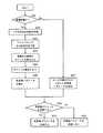
図10は、本実施形態に関わるサーバにおける処理の流れを説明するためのフローチャートである。まず、S201において、サーバの受け取った情報が物理情報であるか、物理情報に関する情報であるかの判別を行なう。サーバの受け取った情報が分光透過率であった場合、S202においてベタの分光反射率を予測する。次にS203においてハーフトーンの分光反射率を予測し、S204においてガマットを算出する。次にS205において、プリントジョブデータの色信号(R,G,B)のL*a*b*均等色空間におけるガマットを上記対象画像出力機器のガマットへの圧縮を行ない、S206にて色変換パラメータ、もしくは色変換テーブルを作成する。 FIG. 10 is a flowchart for explaining the flow of processing in the server according to the present embodiment. First, in S201, it is determined whether the information received by the server is physical information or information related to physical information. If the information received by the server is the spectral transmittance, the solid spectral reflectance is predicted in S202. Next, a halftone spectral reflectance is predicted in S203, and a gamut is calculated in S204. In step S205, the gamut of the color signal (R, G, B) of the print job data in the L * a * b * uniform color space is compressed into the gamut of the target image output device. In step S206, the color conversion parameter is set. Or create a color conversion table.
一方、サーバでは、色材のロット番号全ての組み合わせに応じた色変換パラメータをあらかじめ保持しており、受け取った情報がロット番号の場合、S207において、受け取ったロット番号の組み合わせに応じた色変換パラメータ、もしくは色変換テーブルを選出する。 On the other hand, if the server holds in advance color conversion parameters corresponding to all combinations of lot numbers of color materials, and the received information is a lot number, in S207, the color conversion parameters corresponding to the received combination of lot numbers. Or, select a color conversion table.
次に、上記対象画像出力機器の色変換パラメータを図示しないROM等に記憶記憶させておき、新たに色変換パラメータが作成もしくは選出した場合、ROMにおける色変換パラメータとの比較と行なうことも可能である(S208)。その結果、対象画像出力機器が保持する色変換パラメータと、新たな色変換パラメータとの差異が小さければ、サーバは新たな色変換パラメータを送信せず、画像出力機器において、色変換パラメータの更新も行なわれない(S209)。また、S210において、色変換テーブルは、画像出力機器の制御装置11において、インターフェース13を介してダウンロードされる。 Next, the color conversion parameter of the target image output device is stored and stored in a ROM (not shown) or the like, and when a new color conversion parameter is created or selected, it can be compared with the color conversion parameter in the ROM. Yes (S208). As a result, if the difference between the color conversion parameter held by the target image output device and the new color conversion parameter is small, the server does not transmit the new color conversion parameter, and the image output device also updates the color conversion parameter. Not performed (S209). In S210, the color conversion table is downloaded via the
実施例4(記憶媒体)
上記実施例では、色変換処理をプリンタ1の内部で行うものとして説明したが、プリンタ1とは独立した装置で行っても構わない。また、ホストコンピュータにおいて、プリンタ・ドライバでソフトウェアの形態で行われても良い。Example 4 (storage medium)
In the above embodiment, the color conversion process is described as being performed inside the
図11は、本実施形態に係るプリンタ1の概略機能構成を説明するためのブロック図である。図11に示すように、本実施の形態の色変換処理装置は、マイクロコンピュータを含んで構成された装置本体10、データやコマンドを入力するためのマウス11及びキーボード12、画像データを表示するための13、及びカラープリンタなどの画像出力機器14から構成されている。 FIG. 11 is a block diagram for explaining a schematic functional configuration of the
装置本体10は、CPU21、CPU21の制御プログラム等が記憶されているROM22、RAM23、ハードディスク24、本体と他の装置との間でデータ等をやりとりするためのNIC25及びこれらをデータやコマンドが入出力可能なように接続されたバスから構成されている。 The apparatus main body 10 includes a
このシステムにおいて、本発明の色変換処理としての機能をCPU21にもたせることができる。なお、CPU21におけるこのような色変換処理機能は、例えばソフトウェアパッケージ(具体的には、CD−ROM等の情報記録媒体)の形で提供することができ、このため、図11の例では、情報記録媒体30がセットさせるとき、これを駆動する媒体駆動装置31が設けられている。 In this system, the
換言すれば、本発明の色変換処理は、ディスプレイ等を備えた汎用の計算機システムにCD−ROM等の情報記録媒体に記録されたプログラムを読み込ませて、この汎用計算機システムのマイクロプロセッサに色変換パラメータを算出させ、入力画像の色変換を実行させる装置構成においても実施することが可能である。この場合、本発明の色変換処理を実行するためのプログラム(すなわち、ハードウェアシステムで用いられるプログラム)は、媒体に記録された状態で提供される。プログラムなどが記録される情報記録媒体としては、CD−ROMに限られるものではなく、ROM,RAM,フレキシブルディスク,メモリカード等が用いられても良い。また、プログラムは、媒体の形で提供されるのみならず、通信によって例えばネットワーク上のサーバによって提供されるものであっても良い。 In other words, the color conversion processing according to the present invention causes a general-purpose computer system having a display or the like to read a program recorded on an information recording medium such as a CD-ROM, and performs color conversion on the microprocessor of the general-purpose computer system. The present invention can also be implemented in an apparatus configuration that calculates parameters and executes color conversion of an input image. In this case, a program for executing the color conversion processing of the present invention (that is, a program used in the hardware system) is provided in a state recorded on a medium. The information recording medium on which the program is recorded is not limited to the CD-ROM, and a ROM, RAM, flexible disk, memory card, or the like may be used. Further, the program may be provided not only in the form of a medium but also by a server on a network by communication, for example.
媒体に記録されたプログラムは、ハードウェアシステムに組み込まれている記憶装置、例えばハードディスク24にインストールされることにより、このプログラムを実行して、色変換処理機能を実現することができる。
(クベルカ-ムンク理論について)
図12は、下地の上に充分な厚みXの色剤層がある場合のモデル図である。その中間に微少な厚みdxがあった場合、色剤層に入った光はdxに達する光iと下地に達し反射してきた光jが想定される。このiの散乱光とjの散乱吸収後の透過光の和が上向きの光となりる。このモデルを簡素化すると図中の式(1)になり、反射率から吸収・散乱による光の減衰比率をあらわす数値になる。
このK/S値は反射率とは異なり、色剤層の性質を数値化したもので、色を濃度で見る数値と解釈すると理解しやすくなる。The program recorded on the medium is installed in a storage device incorporated in the hardware system, for example, the
(On the Kubelka-Munk theory)
FIG. 12 is a model diagram when there is a colorant layer having a sufficient thickness X on the base. When there is a minute thickness dx in the middle, light entering the colorant layer is assumed to be light i reaching dx and light j reaching the ground and reflected. The sum of the scattered light of i and the transmitted light of j after being scattered and absorbed becomes upward light. When this model is simplified, Equation (1) in the figure is obtained, and the numerical value represents the attenuation ratio of light due to absorption / scattering from the reflectance.
Unlike the reflectance, this K / S value is obtained by quantifying the properties of the colorant layer, and can be easily understood by interpreting it as a numerical value for viewing the color by density.
色を吸収と散乱で表すことにより、複数の色剤の混合は層が複数あると解釈することができ、反射率・三刺激値では無理であった減法混色での色予測が可能になる。D.R.Duncanは吸光係数K・散乱係数Sに加法性が成り立つことを発見し、図中の式(2)を発表した。 By expressing the color by absorption and scattering, a mixture of a plurality of colorants can be interpreted as having a plurality of layers, and color prediction can be performed with subtractive color mixing, which is impossible with reflectance and tristimulus values. D.R.Duncan discovered that the extinction coefficient K and the scattering coefficient S are additive, and announced the equation (2) in the figure.
式(2)は、下地や白の色剤のS値が充分大きい場合の近似式で、本来の式はKとSは別々に積算される。このように、色剤個々のK/Sが求まれば、混合した時の色が予測できるから、色剤濃度によってK/S値を予測できれば、処方からできあがる色がわかることになりる。色剤個々の濃度に対するK/S値を得るには、K/S値と色材濃度の関数を反射率の各波長単位で求める必要がある。一般的には基礎データと呼ばれる色剤個々に着色したサンプルを複数の濃度で作り、実測値から中間の値を推測している。つまり、濃度が決まればその濃度に対しての波長毎のK/S値が得られることになる(図13)。 Expression (2) is an approximate expression when the S value of the background or white colorant is sufficiently large. In the original expression, K and S are integrated separately. Thus, if the K / S of each colorant is obtained, the color at the time of mixing can be predicted. Therefore, if the K / S value can be predicted based on the colorant concentration, the color obtained from the prescription can be known. In order to obtain the K / S value for the density of each colorant, it is necessary to obtain a function of the K / S value and the color material density for each wavelength unit of reflectance. In general, samples that are individually colored, called basic data, are made at a plurality of concentrations, and an intermediate value is estimated from actual measurement values. That is, if the concentration is determined, a K / S value for each wavelength with respect to the concentration can be obtained (FIG. 13).
1 プリンタ
11 制御装置
12 印刷機構部
13 インタフェース
14 信号処理部
15 駆動回路部
16 ユーザインタフェースDESCRIPTION OF
Claims (11)
Translated fromJapanesePriority Applications (1)
| Application Number | Priority Date | Filing Date | Title |
|---|---|---|---|
| JP2004294523AJP4548718B2 (en) | 2004-10-07 | 2004-10-07 | Image output apparatus, image output method, program, and recording medium |
Applications Claiming Priority (1)
| Application Number | Priority Date | Filing Date | Title |
|---|---|---|---|
| JP2004294523AJP4548718B2 (en) | 2004-10-07 | 2004-10-07 | Image output apparatus, image output method, program, and recording medium |
Publications (2)
| Publication Number | Publication Date |
|---|---|
| JP2006103216Atrue JP2006103216A (en) | 2006-04-20 |
| JP4548718B2 JP4548718B2 (en) | 2010-09-22 |
Family
ID=36373451
Family Applications (1)
| Application Number | Title | Priority Date | Filing Date |
|---|---|---|---|
| JP2004294523AExpired - Fee RelatedJP4548718B2 (en) | 2004-10-07 | 2004-10-07 | Image output apparatus, image output method, program, and recording medium |
Country Status (1)
| Country | Link |
|---|---|
| JP (1) | JP4548718B2 (en) |
Cited By (4)
| Publication number | Priority date | Publication date | Assignee | Title |
|---|---|---|---|---|
| US8170460B2 (en)* | 2008-05-16 | 2012-05-01 | Ricoh Company, Ltd. | Image forming apparatus, image forming method, and printing medium |
| JP2015046696A (en)* | 2013-08-27 | 2015-03-12 | キヤノン株式会社 | System, method, and program |
| JP2016132237A (en)* | 2015-01-22 | 2016-07-25 | 理想科学工業株式会社 | Printing system and ink cartridge |
| JP2019153829A (en)* | 2018-02-28 | 2019-09-12 | キヤノン株式会社 | Color image forming apparatus and color material cartridge |
Citations (6)
| Publication number | Priority date | Publication date | Assignee | Title |
|---|---|---|---|---|
| JP2001105703A (en)* | 1999-10-12 | 2001-04-17 | Wedge:Kk | Thermal transfer ribbon cassette |
| JP2001109337A (en)* | 1999-10-08 | 2001-04-20 | Murata Mach Ltd | Image forming device |
| JP2002056251A (en)* | 2000-08-09 | 2002-02-20 | Seiko Epson Corp | Colored cartridge ordering system and computer-readable recording medium in which a colored cartridge ordering program is written |
| JP2002234202A (en)* | 2001-02-09 | 2002-08-20 | Sony Corp | Printer and printing method |
| JP2004072146A (en)* | 2002-08-01 | 2004-03-04 | Fuji Photo Film Co Ltd | Recording material and photographing apparatus |
| JP2004258075A (en)* | 2003-02-24 | 2004-09-16 | Murata Mach Ltd | Image processing apparatus |
- 2004
- 2004-10-07JPJP2004294523Apatent/JP4548718B2/ennot_activeExpired - Fee Related
Patent Citations (6)
| Publication number | Priority date | Publication date | Assignee | Title |
|---|---|---|---|---|
| JP2001109337A (en)* | 1999-10-08 | 2001-04-20 | Murata Mach Ltd | Image forming device |
| JP2001105703A (en)* | 1999-10-12 | 2001-04-17 | Wedge:Kk | Thermal transfer ribbon cassette |
| JP2002056251A (en)* | 2000-08-09 | 2002-02-20 | Seiko Epson Corp | Colored cartridge ordering system and computer-readable recording medium in which a colored cartridge ordering program is written |
| JP2002234202A (en)* | 2001-02-09 | 2002-08-20 | Sony Corp | Printer and printing method |
| JP2004072146A (en)* | 2002-08-01 | 2004-03-04 | Fuji Photo Film Co Ltd | Recording material and photographing apparatus |
| JP2004258075A (en)* | 2003-02-24 | 2004-09-16 | Murata Mach Ltd | Image processing apparatus |
Cited By (6)
| Publication number | Priority date | Publication date | Assignee | Title |
|---|---|---|---|---|
| US8170460B2 (en)* | 2008-05-16 | 2012-05-01 | Ricoh Company, Ltd. | Image forming apparatus, image forming method, and printing medium |
| JP2015046696A (en)* | 2013-08-27 | 2015-03-12 | キヤノン株式会社 | System, method, and program |
| JP2016132237A (en)* | 2015-01-22 | 2016-07-25 | 理想科学工業株式会社 | Printing system and ink cartridge |
| JP2019153829A (en)* | 2018-02-28 | 2019-09-12 | キヤノン株式会社 | Color image forming apparatus and color material cartridge |
| US11310387B2 (en) | 2018-02-28 | 2022-04-19 | Canon Kabushiki Kaisha | Color image forming apparatus and color material cartridge |
| JP7057685B2 (en) | 2018-02-28 | 2022-04-20 | キヤノン株式会社 | Color image forming device and color material cartridge |
Also Published As
| Publication number | Publication date |
|---|---|
| JP4548718B2 (en) | 2010-09-22 |
Similar Documents
| Publication | Publication Date | Title |
|---|---|---|
| JP6510659B2 (en) | Color calibration | |
| CN104219422B (en) | Color adjustment system and color adjustment method | |
| US6950197B1 (en) | Calibration method, information processing apparatus and information processing system | |
| JP7643067B2 (en) | Image processing device, image processing method, and program | |
| JP2008244644A (en) | Image forming apparatus, image forming method and image forming program | |
| US10346111B2 (en) | Print image processing device, print image processing system, and display method of print image selection screen | |
| JP4661932B2 (en) | Image forming apparatus and image forming control program | |
| JP4548718B2 (en) | Image output apparatus, image output method, program, and recording medium | |
| JP2009071617A (en) | Image processing apparatus, image processing method, and program | |
| WO2007137624A1 (en) | Ad-hoc color gamut representation | |
| US20150213343A1 (en) | Method, apparatus, and program for generating color conversion lookup table | |
| JP2010158824A (en) | Printing apparatus, color correcting method, and program | |
| US11842096B2 (en) | Print control based on the difference in the residual quantity ratio of toners | |
| JP2015119371A (en) | Color profile creation system, color profile creation method and program | |
| JP2023175403A (en) | Printer, printing method and printing program | |
| US11310387B2 (en) | Color image forming apparatus and color material cartridge | |
| JP2010028310A (en) | Inkjet printer color adjustment method and inkjet printer | |
| JP4572648B2 (en) | Print control apparatus, print control system, print control method, print control program, and apparatus, method and program for creating color correction data | |
| JP2020151966A (en) | Information processing device, image formation apparatus and program | |
| JP7631772B2 (en) | Printing Systems and Printers | |
| JP2006159709A (en) | Image output apparatus, image output method, and recording medium | |
| JP2006229554A (en) | Printing system | |
| JP2004056271A (en) | Image processing apparatus and method | |
| US10778871B1 (en) | Information processing and forming with user selection of color material filling containers and display of color image | |
| JP2009232229A (en) | Image processing system, image processing program and image processing method |
Legal Events
| Date | Code | Title | Description |
|---|---|---|---|
| A621 | Written request for application examination | Free format text:JAPANESE INTERMEDIATE CODE: A621 Effective date:20070927 | |
| A131 | Notification of reasons for refusal | Free format text:JAPANESE INTERMEDIATE CODE: A131 Effective date:20100421 | |
| A521 | Written amendment | Free format text:JAPANESE INTERMEDIATE CODE: A523 Effective date:20100608 | |
| TRDD | Decision of grant or rejection written | ||
| A01 | Written decision to grant a patent or to grant a registration (utility model) | Free format text:JAPANESE INTERMEDIATE CODE: A01 Effective date:20100630 | |
| A01 | Written decision to grant a patent or to grant a registration (utility model) | Free format text:JAPANESE INTERMEDIATE CODE: A01 | |
| A61 | First payment of annual fees (during grant procedure) | Free format text:JAPANESE INTERMEDIATE CODE: A61 Effective date:20100701 | |
| FPAY | Renewal fee payment (event date is renewal date of database) | Free format text:PAYMENT UNTIL: 20130716 Year of fee payment:3 | |
| LAPS | Cancellation because of no payment of annual fees |