JP2006102093A - Medical treatment instrument - Google Patents
Medical treatment instrumentDownload PDFInfo
- Publication number
- JP2006102093A JP2006102093AJP2004292433AJP2004292433AJP2006102093AJP 2006102093 AJP2006102093 AJP 2006102093AJP 2004292433 AJP2004292433 AJP 2004292433AJP 2004292433 AJP2004292433 AJP 2004292433AJP 2006102093 AJP2006102093 AJP 2006102093A
- Authority
- JP
- Japan
- Prior art keywords
- joint
- medical treatment
- treatment instrument
- blades
- shaft
- Prior art date
- Legal status (The legal status is an assumption and is not a legal conclusion. Google has not performed a legal analysis and makes no representation as to the accuracy of the status listed.)
- Pending
Links
- 239000002184metalSubstances0.000claimsdescription6
- 238000005452bendingMethods0.000claimsdescription4
- 206010028980NeoplasmDiseases0.000description9
- 230000005540biological transmissionEffects0.000description7
- 206010062767HypophysitisDiseases0.000description5
- 210000003635pituitary glandAnatomy0.000description5
- 238000000034methodMethods0.000description4
- 230000006835compressionEffects0.000description3
- 238000007906compressionMethods0.000description3
- 238000001356surgical procedureMethods0.000description3
- 210000003128headAnatomy0.000description2
- 229910001220stainless steelInorganic materials0.000description2
- 239000010935stainless steelSubstances0.000description2
- 101100008048Caenorhabditis elegans cut-4 geneProteins0.000description1
- 229910045601alloyInorganic materials0.000description1
- 239000000956alloySubstances0.000description1
- 238000004140cleaningMethods0.000description1
- 230000003247decreasing effectEffects0.000description1
- 238000002674endoscopic surgeryMethods0.000description1
- 238000000605extractionMethods0.000description1
- KHYBPSFKEHXSLX-UHFFFAOYSA-NiminotitaniumChemical compound[Ti]=NKHYBPSFKEHXSLX-UHFFFAOYSA-N0.000description1
- 210000003928nasal cavityAnatomy0.000description1
- 229910001000nickel titaniumInorganic materials0.000description1
- 230000000149penetrating effectEffects0.000description1
- 230000002093peripheral effectEffects0.000description1
- 230000001817pituitary effectEffects0.000description1
- 230000000717retained effectEffects0.000description1
- 230000001954sterilising effectEffects0.000description1
- 238000004659sterilization and disinfectionMethods0.000description1
- 230000001225therapeutic effectEffects0.000description1
Images


Landscapes
- External Artificial Organs (AREA)
- Surgical Instruments (AREA)
- Endoscopes (AREA)
Abstract
Description
Translated fromJapanese本発明は、鉗子、鋏、キュレット、吸引管等の医療用処置具に関する。 The present invention relates to a medical treatment instrument such as forceps, scissors, curette, and suction tube.
従来、鉗子等の医療用処置具は鋏状に構成され、手元のレバーを操作して先端のブレードを開閉動作させ患部の組織等を除去したり、切除したりするようになっている。 2. Description of the Related Art Conventionally, medical treatment tools such as forceps are configured in a saddle shape, and a lever at a hand is operated to open and close a blade at a distal end so as to remove or excise affected tissue.
ところが、従来の医療用処置具は例えば鉗子であれば軸部の先でブレードを単に開閉動作させるようになっているだけであるから、患者の体内に確保したトンネル状の通路から鉗子を挿入した場合、通路の突き当たりの箇所については処置することができるが、この突き当りの周辺をある程度の広がりを持って処置することができないという問題がある。 However, since the conventional medical treatment tool, for example, is a forceps, the blade is simply opened and closed at the end of the shaft, so the forceps were inserted from a tunnel-shaped passage secured in the patient's body. In this case, the end of the passage can be treated, but there is a problem that the periphery of the end cannot be treated with a certain extent.
例えば、下垂体手術のような狭い箇所の手術では、腫瘍を取り除くためには一種類の鉗子で患部にアプローチすることが難しく、処理部の形状を変えた多種類の鉗子を使用して行われる。そのため、手術が煩雑となり術者と患者の双方に負担がかかるという問題がある。 For example, in a narrow part surgery such as pituitary surgery, it is difficult to approach the affected area with a single type of forceps in order to remove the tumor, and it is performed using a variety of types of forceps whose shape of the processing part has been changed. . Therefore, there is a problem that the operation becomes complicated and burdens both the operator and the patient.
また、鉗子の軸部とブレードとの間にヒンジピン等を設けることによりブレードを首振り可能とすることで、上記問題を解決することも可能であるとも考えられるが、その場合は屈曲部の箇所が大径化したり長寸化したりし、却って患部にアプローチし難くなるという問題がある。また、ブレード等を遠隔操作するためのケーブル等を配置し難いという問題がある。 In addition, it is considered that the above problem can be solved by providing a hinge pin or the like between the shaft portion of the forceps and the blade so that the above-mentioned problem can be solved. However, there is a problem that it becomes difficult to approach the affected area. In addition, there is a problem that it is difficult to arrange a cable or the like for remotely operating the blade or the like.
したがって、本発明は上記不具合を解消することができる医療用処置具を提供することを目的とする。 Therefore, an object of the present invention is to provide a medical treatment instrument that can solve the above-mentioned problems.
上記課題を解決するため、請求項1に係る発明は、軸部(1)の先端と後端にそれぞれ処理部(2)と基部(3)を備え、処理部(2)が軸部(1)に対し継手(4)を介して連結された医療用処置具において、上記継手(4)が、複数個の短管(4a,4b,4c,4d)と、短管(4a,4b,4c,4d)同士をそれらの共通軸を挟む二本の母線上で連結する可撓片(4e)とを有し、この継手(4)を介し処理部(2)が軸部(1)の先端で首振り可能とされた医療用処置具を採用する。 In order to solve the above problems, the invention according to claim 1 is provided with a processing portion (2) and a base portion (3) at the front end and the rear end of the shaft portion (1), respectively, and the processing portion (2) is the shaft portion (1). ), The joint (4) includes a plurality of short tubes (4a, 4b, 4c, 4d) and a short tube (4a, 4b, 4c). , 4d) and a flexible piece (4e) for connecting two common buses with the common shaft between them, and the processing portion (2) is connected to the tip of the shaft portion (1) through the joint (4). A medical treatment tool that can be swung with a head is adopted.
また、請求項2に係る発明は、請求項1に記載の医療用処置具において、弾性を有する金属管の両側面にそれぞれ複数箇所にわたって切込(4f)を入れることにより、上記継手(4)の短管(4a,4b,4c,4d)及び可撓片(4e)が形成された医療用処置具を採用する。 The invention according to
また、請求項3に係る発明は、請求項1又は請求項2に記載の医療用処置具において、上記継手(4)の内壁面に、継手(4)を屈曲操作する伝動用線体(26a,26b)の通る溝(4g)が形成された医療用処置具を採用する。 The invention according to
また、請求項4に係る発明は、請求項1乃至請求項3のいずれかに記載の医療用処置具において、上記継手(4)の中空内にコイルスプリング(10)が挿入された医療用処置具を採用する。 The invention according to
請求項1に係る発明によれば、軸部(1)の先端と後端にそれぞれ処理部(2)と基部(3)を備え、処理部(2)が軸部(1)に対し継手(4)を介して連結された医療用処置具において、上記継手(4)が、複数個の短管(4a,4b,4c,4d)と、短管(4a,4b,4c,4d)同士をそれらの共通軸を挟む二本の母線上で連結する可撓片(4e)とを有し、この継手(4)を介し処理部(2)が軸部(1)の先端で首振り可能とされたことから、継手(4)が細くかつ短くなり小さい曲率半径で屈曲可能となり、従って患部にアプローチしやすくなる。また、処理部(2)や継手(4)を操作するためのケーブル、ロッド等を継手(4)の内部の空洞内に収納することができ、従ってこの点からも患部にアプローチしやすくなる。 According to the invention which concerns on Claim 1, it equips the front-end | tip and the rear end of a shaft part (1) with a process part (2) and a base (3), respectively, and a process part (2) is a joint ( 4) In the medical treatment instrument connected via 4), the joint (4) includes a plurality of short tubes (4a, 4b, 4c, 4d) and short tubes (4a, 4b, 4c, 4d). A flexible piece (4e) connected on two bus bars sandwiching the common shaft, and the processing portion (2) can swing at the tip of the shaft portion (1) through the joint (4). As a result, the joint (4) is thin and short, and can be bent with a small radius of curvature, and therefore, it is easy to approach the affected area. In addition, cables, rods, and the like for operating the processing unit (2) and the joint (4) can be accommodated in the cavity inside the joint (4). Therefore, it is easy to approach the affected part also in this respect.
請求項2に係る発明によれば、請求項1に記載の医療用処置具において、弾性を有する金属管の両側面にそれぞれ複数箇所にわたって切込(4f)を入れることにより、上記継手(4)の短管(4a,4b,4c,4d)及び可撓片(4e)が形成されたことから、継手(4)を簡易に製作することができる。 According to the invention according to
請求項3に係る発明によれば、請求項1又は請求項2に記載の医療用処置具において、上記継手(4)の内壁面に、継手(4)を屈曲操作する伝動用線体(26a,26b)の通る溝(4g)が形成されたことから、継手(4)を屈曲操作するワイヤ、ロッド等の伝動用線体(26a,26b)を継手(4)の内壁面の溝(4g)内に収めることができ、伝動用線体(26a,26b)を円滑に案内することができる。 According to the invention which concerns on
請求項4に係る発明によれば、請求項1乃至請求項3のいずれかに記載の医療用処置具において、上記継手(4)の中空内にコイルスプリング(10)が挿入されたことから、継手(4)の空洞内に人体の組織等が入り込み難くすることができる。 According to the invention according to
以下、図面を参照して発明を実施するための最良の形態について説明する。 The best mode for carrying out the invention will be described below with reference to the drawings.
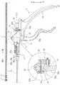
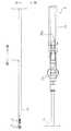
図1乃至図5に示すように、この医療用処置具である鉗子は、軸部1の先端と後端にそれぞれ処理部2と基部3を備える。 As shown in FIGS. 1 to 5, the forceps as the medical treatment tool includes a
軸部1は、剛性のある例えばステンレス鋼製のパイプ1aで形成され、鼻腔等に挿入可能に細長く形成される。 The shaft portion 1 is formed of a rigid pipe 1a made of, for example, stainless steel, and is formed in an elongated shape so that it can be inserted into a nasal cavity or the like.
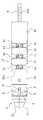
処理部2は、図1〜図4、図6〜図8に示すように、鉗子用の一対のブレード2a,2bを備える。一対のブレード2a,2bはホルダ5に回動可能に支持される。一対のブレード2a,2bの後端はホルダ5の先端に形成された縦溝内の上下にそれぞれ挿入され、縦溝を横断する各支点ピン6によりホルダ5に枢着される。また、各ブレード2a,2bからは支点ピン6を越えて上記縦溝内で重畳するアーム7が突出し、アーム7は重なり合った状態でスライダ8の先端に一本の枢ピン9で連結される。スライダ8はホルダ5を前後方向に貫通するガイド孔5a内にスライド可能に挿入される。図8(A)〜(D)に示すように、スライダ8がホルダ5のガイド孔5a内を前方にスライドすると一対のブレード2a,2bが開き、逆に後方にスライドすると図8(D)〜(A)に示すように一対のブレード2a,2bが閉じる。 As shown in FIGS. 1 to 4 and FIGS. 6 to 8, the
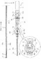
処理部2は、図1乃至図3に示すように、軸部1の先端に屈曲可能な継手4を介し連結され、図7に示すように、平面上での首振り動作が可能になっている。 As shown in FIGS. 1 to 3, the
図6、図7及び図9(A)〜(E)に示すように、継手4は、複数個の短管4a,4b,4c,4dと、短管4a,4b,4c,4d同士をそれらの共通軸を挟む二本の母線上で隙間が空くように連結する可撓片4eとを有する。両端の短管4a,4dはホルダ5と軸部1に連結するので多少長めに形成されるが、中間の短管4b,4cは外径に比べ長さが短い筒体として形成される。可撓片4eは短管4a,4b,4c,4dの端面間において半径方向及び軸方向に延びる板片として形成される。継手4は短管と可撓片とを別個に形成した後で接合することによっても作ることができるが、この実施の形態では、弾性を有する金属管の両側面にそれぞれ複数箇所にわたって半径方向に切込4fを入れることにより短管4a,4b,4c,4d及び可撓片4eが当初から一体で形成され、短管4a,4b,4c,4d同士の間に隙間が形成される。切込4fは図9(A)に示すように半径方向に入れた後に更に軸方向に延長することにより、上記可撓片4eをより長く形成し、板バネを屈曲しやすくすることができる。継手4の短管4b,4c及び可撓片4eは自在に増減可能であり、その増減により処理部2の屈曲角や屈曲方向を適宜変更することができる。金属管としては例えばNi−Ti合金やステンレス鋼を用いることができ、ワイヤカットとマシニングセンタを使用して金属管から継手4を切り出すことができる。 As shown in FIGS. 6, 7 and 9A to 9E, the
また、継手4の内壁面には、継手4を屈曲操作するための図7に示すような伝動用線体であるケーブル26a,26bの通る溝4gが形成される。この溝4gは継手4の内壁面の円筒面において、上記可撓片4eの位置と90度位相がずれた二本の母線上に夫々形成される。伝動用線体としてはケーブル26a,26bのほか、ワイヤ、ロッド等を用いることができるが、この実施の形態では屈曲自在なケーブルが用いられる。二本のケーブル26a,26bが継手4の内面の各溝4g内にスライド可能に収納される。 Further, the inner wall surface of the
この継手4の後端には、図9(C)(E)に示すように大径の保持穴4hが形成され、この保持穴4h内に軸部1のパイプ1aの先端が挿入され固定される。また、継手4の前端には、図9(C)に示すように大径の係合穴4iが形成され、この係合穴4i内に図8に示すように上記ホルダ5の後部が挿入され保持される。これにより、継手4が図7に示すごとく平面上で屈曲すると、処理部2のブレード2a,2bは軸部1の先で継手4が屈曲する方向に首振り動作することになる。 As shown in FIGS. 9C and 9E, a large-
図6及び図7に示すように、上記継手4の中空内にはコイルスプリング10が挿入される。コイルスプリング10は継手4の内側から切込4fを遮蔽するように設けられる。これにより、継手4の空洞内に人体の組織等が入り込み難くし、洗浄、殺菌等を行いやすくすることができる。 As shown in FIGS. 6 and 7, a
上記処理部2のブレード2a,2bは、継手4と共に首振り動作が可能なだけでなく継手4上で軸回りに回転可能でもある。すなわち、図8に示すように、ホルダ5の後部の外周には環状溝12が形成され、この環状溝12内に継手の先端に植設されたガイドピン13が挿入される。これにより、スライダ8が軸回りに捩られると、ブレード2a,2b等を介しスライダ8に連結されたホルダ5が、ガイドピン13と環状溝12との摺接作用で継手4に対し軸回りに回転する。 The
基部3は、図1乃至図5に示すように、その前部で軸部1の後端を保持し、その下側には術者が把持するハンドル14が設けられる。また、基部3には、ハンドル14を持つ術者の指で操作しうるように、ブレード開閉操作部15と、ブレード回転操作部16と、ブレード首振り操作部17とが設けられる。 As shown in FIGS. 1 to 5, the
ブレード開閉操作部15は、図1乃至図5に示すように、開閉操作レバー15aと、開閉操作レバー15aの動きをブレード2a,2bに伝達する伝動用線体であるワイヤ18とを具備する。開閉操作レバー15aは、ハンドル14を持つ手の指で引くことができるように基部3に支点ピン19を介して保持され、基部3に埋設された弾性体である圧縮コイルバネ32により同じく基部3に埋設されたプランジャ33を介し常時前方に付勢される。ワイヤ18は、ブレード2a,2b後方のスライダ8と開閉操作レバー15aとの間に伝動可能に掛け渡される。具体的には、ワイヤ18は上記軸部1と上記継手4の中空内を前後方向に貫通し、その前端は図8に示すようにスライダ8に連結される。また、後端は軸部1の中空に連通するように基部3に形成された貫通孔を後方に貫通し長さ調整具21に連結される。 As shown in FIGS. 1 to 5, the blade opening / closing operation unit 15 includes an opening /
長さ調整具21は、具体的にはコレットチャックであり、基部3の後端にて貫通孔内に挿入され回動可能に保持されるコレット21aと、コレット21aの外周に螺合するナット21bとを具備する。コレット21aには図示しない複数個のすり割り溝が形成され、ナット21bの回転により縮径するようになっている。ワイヤ18をコレット21aに通しブレード2a,2bの開閉に都合のよい長さに調整した後、ナット21bを回することによりコレット21aでワイヤ18を締め付け固定することができる。 The
ワイヤ18と開閉操作レバー15aとは直結してもよいが、この実施の形態では図1に示すように凹凸部の係合を介して動力的に連結される。すなわち、環状凹溝23aを有するパイプ23がワイヤ18に固着され、このパイプ23及びワイヤ18が開閉操作レバー15aに形成された通孔22を前後方向に貫通する。そして、開閉操作レバー15aの通孔22内に形成された突起22aがパイプ23の環状凹溝23aに嵌り込んでいる。 Although the
これにより、開閉操作レバー15aは上記圧縮コイルバネ32によりプランジャ33を介して背後から押されて図1中実線で示す位置に停止し、その突起22aが環状凹溝23aを介してパイプ23及びワイヤ18を前方にスライドさせる。その結果、ブレード2a,2bが図1及び図8(D)に示すように開いた状態となる。そこで、開閉操作レバー15aが圧縮コイルバネ32の付勢力に抗して引かれると、開閉操作レバー15aの突起22aが環状凹溝23aを介してパイプ23及びワイヤ18を後方にスライドさせ、その結果図8(C)〜(A)のごとく、ブレード2a,2bが閉じる。 As a result, the opening /
ブレード回転操作部16は、図1乃至図5に示すように、回転操作ダイアル16aを備える。回転操作ダイアル16aは、上記基部3に回動可能に連結されたコレット21aに固着され、上記ハンドル14を持つ手の指で回転操作ダイアル16aを回すと、ワイヤ18が軸回りに回転する。上述のごとくワイヤ18の先端はスライダ8を介しブレード2a,2bのアーム7に連結されているので、回転操作ダイアル16aの回転に伴いブレード2a,2bも軸回りに回転する。 The blade
ブレード首振り操作部17は、図1、図2、図6及び図7に示すように、首振り操作ダイアル17aと、首振り操作ダイアル17aの動きを処理部2に伝達する伝動用線体であるケーブル26a,26bとを具備する。首振り操作ダイアル17aは基部3における開閉操作レバー15aよりもやや前方に支点軸27を介し軸支される。図1及び図2に示すように、首振り操作ダイアル17aの下方の基部3内には、左右二つの滑り子25a,25bが前後方向にスライド自在に配置され、各滑り子25a,25bにケーブル26a,26bの後端がそれぞれ連結される。また、各滑り子25a,25bにはローラ状のカムフォロア31が取り付けられ、操作ダイアル17aにはカムフォロア31が入り込む空洞30が形成され、空洞30内に偏心カム30aが設けられる。偏心カム30aは図2に示すように初期位置において左右の両カムフォロア31に左右対称的に接触する。ケーブル26a,26bは上記ワイヤ18を間に挟むように軸部1内を前方に貫通して伸び、さらに継手4の溝4g内を前方に貫通して伸び、それぞれの前端がホルダ5に連結される。 As shown in FIGS. 1, 2, 6, and 7, the blade
これにより、上記ハンドル14を持つ手の指で首振り操作ダイアル17aを回すと、偏心カム30aとカムフォロア31との摺接により左右の滑り子25a,25bが基部3内を互いに前後逆向きにスライドし、これに伴い左右のケーブル26a,26bが軸部1及び継手4内を互いに逆向きにスライドする。その結果、図7(B)に示すように継手4が平面上で屈曲し、首振り操作ダイアル17aの回転方向に応じて処理部2のブレード2a,2bが継手4と共に首を振る。 As a result, when the
また、首振り操作ダイアル17aの外周面には多数の凹溝20が所定のピッチで形成され、基部3内にはいずれかの凹溝20に嵌り込む凸片20aが設けられる。凸片20aは図示しないスプリングにより常時凹溝側に付勢される。凸片20aと凹溝20との係合により、ブレード2a,2b及び継手4は所望の首振り位置に保持される。 In addition, a large number of
次に、上記構成の医療用処置具の作用について説明する。 Next, the operation of the medical treatment tool having the above configuration will be described.
図10に示すように、例えばこの治療用処置具を下垂体の腫瘍Aの摘出に使用するものとする。まず、図示しない鼻鏡を鼻孔Bから下垂体の方へと挿入し、鼻鏡をガイドとして内視鏡Cを下垂体へと挿入し、内視鏡Cにより患部を照明する。 As shown in FIG. 10, for example, this therapeutic treatment tool is used for extraction of tumor A of the pituitary gland. First, a nasal mirror (not shown) is inserted from the nostril B toward the pituitary gland, the endoscope C is inserted into the pituitary gland using the nasal mirror as a guide, and the affected part is illuminated by the endoscope C.
術者が医療用処置具のハンドル14を持ち、開閉操作レバー15aを図示しない弾性体の付勢力に抗して後方へと引く。これにより、ワイヤ18が軸部1及び継手4の内部を後方にスライドし図8(D)〜(A)のごとくブレード2a,2bを閉動作させる。 The operator holds the
鼻鏡をガイドとしてこの閉じたブレード2a,2bから軸部1を鼻孔B内に挿入する。ブレード2a,2bが下垂体の腫瘍Aに到達すると開閉操作レバー15aを解放する。弾性体の復元作用により開閉操作レバー15aが元の位置に復帰し、これに伴い図8(A)のごとくブレード2a,2bが開く。 The shaft portion 1 is inserted into the nostril B through the
続いて、回転操作ダイアル16aや首振り操作ダイアル17aを、ハンドル14を持つ手の指で操作し、ブレード2a,2bを軸回りに回転させ、或いは首振り動作させて、ブレード2a,2bを腫瘍Aに接近させる。その際、ワイヤ18やケーブル26a,26bは軸部1及び継手4の内部をスライドする。 Subsequently, the
そこで、開閉操作レバー15aを引き操作し、図8(D)〜(A)のごとくブレード2a,2bを閉動作させ、ブレード2a,2bで腫瘍Aを掴み、首振り操作ダイアル17aを逆向きに操作してブレード2a,2bを軸部1の延長線上に戻した後、軸部1を鼻鏡外に引き出す。これにより、腫瘍Aが体外に除去される。 Accordingly, the opening /
上記操作を腫瘍Aの大きさに応じて繰り返し行い、腫瘍Aの全体を体外に摘出する。 The above operation is repeated according to the size of the tumor A, and the entire tumor A is removed from the body.
このように、軸部1を患者の体内に挿入した場合に基部3の首振り操作部17を操作して継手4の箇所で処理部2を首振り動作させることができるので、患者の体内における処理部2の突き当りの周辺をある程度の広がりを持って処置することができる。また、継手4は細くかつ短いので小さい曲率半径で屈曲可能であり、従って下垂体の腫瘍Aのごとき小さい患部に対してもアプローチしやすい。 In this way, when the shaft portion 1 is inserted into the patient's body, the swinging
なお、本発明は上記実施の形態に限定されるものではなく、例えば上記実施の形態では内視鏡手術用の鉗子として説明したが、鋏、キュレット、吸引管等の医療用処置具についても適用可能である。鋏、キュレット、吸引管の場合は処理部がそれぞれ一対の刃、キュレット片、吸引口として構成される。吸引管として使用する場合は、軸部等に挿入されるワイヤに代えて吸引パイプが挿入される。 The present invention is not limited to the above-described embodiment. For example, in the above-described embodiment, the forceps for endoscopic surgery has been described. However, the present invention is also applicable to medical treatment instruments such as scissors, curettes, and suction tubes. Is possible. In the case of a scissors, a curette, and a suction tube, the processing units are each configured as a pair of blades, a curette piece, and a suction port. When used as a suction tube, a suction pipe is inserted in place of the wire inserted into the shaft or the like.
1…軸部
2…処理部
3…基部
4…継手
4a,4b,4c,4d…短管
4e…可撓片
4f…切込
4g…溝
10…コイルスプリング
26a,26b…ケーブルDESCRIPTION OF SYMBOLS 1 ...
Claims (4)
Translated fromJapanesePriority Applications (1)
| Application Number | Priority Date | Filing Date | Title |
|---|---|---|---|
| JP2004292433AJP2006102093A (en) | 2004-10-05 | 2004-10-05 | Medical treatment instrument |
Applications Claiming Priority (1)
| Application Number | Priority Date | Filing Date | Title |
|---|---|---|---|
| JP2004292433AJP2006102093A (en) | 2004-10-05 | 2004-10-05 | Medical treatment instrument |
Publications (1)
| Publication Number | Publication Date |
|---|---|
| JP2006102093Atrue JP2006102093A (en) | 2006-04-20 |
Family
ID=36372472
Family Applications (1)
| Application Number | Title | Priority Date | Filing Date |
|---|---|---|---|
| JP2004292433APendingJP2006102093A (en) | 2004-10-05 | 2004-10-05 | Medical treatment instrument |
Country Status (1)
| Country | Link |
|---|---|
| JP (1) | JP2006102093A (en) |
Cited By (7)
| Publication number | Priority date | Publication date | Assignee | Title |
|---|---|---|---|---|
| JP2007307022A (en)* | 2006-05-17 | 2007-11-29 | Pentax Corp | Endoscope pipe connection structure |
| JP2010075375A (en)* | 2008-09-25 | 2010-04-08 | Kanazawa Univ | Forceps |
| WO2013162229A1 (en)* | 2012-04-25 | 2013-10-31 | 주식회사 고영테크놀러지 | Bendable end effector |
| KR101441341B1 (en)* | 2012-04-25 | 2014-09-17 | 주식회사 고영테크놀러지 | Bending type end-effector |
| WO2017043128A1 (en)* | 2015-09-11 | 2017-03-16 | オリンパス株式会社 | Medical treatment instrument |
| KR102043627B1 (en)* | 2019-03-18 | 2019-11-12 | 맥스폴 주식회사 | Flexible dissection apparatus |
| JP2022047656A (en)* | 2020-09-14 | 2022-03-25 | 株式会社Lake・E2 | Endoscopic treatment tool |
Citations (5)
| Publication number | Priority date | Publication date | Assignee | Title |
|---|---|---|---|---|
| JPH0889475A (en)* | 1994-09-28 | 1996-04-09 | Asahi Optical Co Ltd | Endoscopic treatment tool |
| JPH08336540A (en)* | 1994-12-19 | 1996-12-24 | Ethicon Endo Surgery Inc | Equipment for surgery |
| JPH09276413A (en)* | 1995-12-07 | 1997-10-28 | Sarcos Inc | Hollow guide wire for catheter |
| JP2001137251A (en)* | 1999-11-17 | 2001-05-22 | Hitachi Ltd | Treatment tool |
| JP2002301088A (en)* | 2001-04-05 | 2002-10-15 | Olympus Optical Co Ltd | Endoscopic treatment device |
- 2004
- 2004-10-05JPJP2004292433Apatent/JP2006102093A/enactivePending
Patent Citations (5)
| Publication number | Priority date | Publication date | Assignee | Title |
|---|---|---|---|---|
| JPH0889475A (en)* | 1994-09-28 | 1996-04-09 | Asahi Optical Co Ltd | Endoscopic treatment tool |
| JPH08336540A (en)* | 1994-12-19 | 1996-12-24 | Ethicon Endo Surgery Inc | Equipment for surgery |
| JPH09276413A (en)* | 1995-12-07 | 1997-10-28 | Sarcos Inc | Hollow guide wire for catheter |
| JP2001137251A (en)* | 1999-11-17 | 2001-05-22 | Hitachi Ltd | Treatment tool |
| JP2002301088A (en)* | 2001-04-05 | 2002-10-15 | Olympus Optical Co Ltd | Endoscopic treatment device |
Cited By (9)
| Publication number | Priority date | Publication date | Assignee | Title |
|---|---|---|---|---|
| JP2007307022A (en)* | 2006-05-17 | 2007-11-29 | Pentax Corp | Endoscope pipe connection structure |
| JP2010075375A (en)* | 2008-09-25 | 2010-04-08 | Kanazawa Univ | Forceps |
| WO2013162229A1 (en)* | 2012-04-25 | 2013-10-31 | 주식회사 고영테크놀러지 | Bendable end effector |
| KR101441341B1 (en)* | 2012-04-25 | 2014-09-17 | 주식회사 고영테크놀러지 | Bending type end-effector |
| WO2017043128A1 (en)* | 2015-09-11 | 2017-03-16 | オリンパス株式会社 | Medical treatment instrument |
| US10617437B2 (en) | 2015-09-11 | 2020-04-14 | Olympus Corporation | Medical treatment implement |
| KR102043627B1 (en)* | 2019-03-18 | 2019-11-12 | 맥스폴 주식회사 | Flexible dissection apparatus |
| JP2022047656A (en)* | 2020-09-14 | 2022-03-25 | 株式会社Lake・E2 | Endoscopic treatment tool |
| JP7482592B2 (en) | 2020-09-14 | 2024-05-14 | レイクR&D株式会社 | Endoscopic treatment tools |
Similar Documents
| Publication | Publication Date | Title |
|---|---|---|
| US6273860B1 (en) | Biopsy apparatus | |
| EP2810607B1 (en) | Endoscopic treatment instrument | |
| JP2024084812A (en) | End tool of surgical instrument and surgical instrument including same | |
| US6159162A (en) | Biopsy apparatus | |
| JP2025013627A (en) | Forceps with two-part drive bar | |
| JP4354216B2 (en) | LINKING DEVICE FOR TREATMENT TOOL AND TREATMENT TOOL | |
| JP4965005B2 (en) | Endoscopy forceps | |
| WO2010026991A1 (en) | Treating endoscope | |
| JP5671682B2 (en) | Endoscopic instrument | |
| JP2008017876A (en) | Medical treatment instrument | |
| JPH10127651A (en) | Treatment tool for operation | |
| JP4350420B2 (en) | Endoscopy forceps | |
| JP6045755B2 (en) | Suture needle holder and endoscope system | |
| CN115279287B (en) | Surgical instruments | |
| JP2018033501A (en) | Treatment tool for endoscope | |
| JP2006102093A (en) | Medical treatment instrument | |
| CN115317080A (en) | Minimally invasive surgical instrument with bending and infinite rotation functions and convenient to operate | |
| CN216652407U (en) | Cannula assembly and ultrasonic blade | |
| JP4402313B2 (en) | Surgical treatment tool and surgical treatment apparatus | |
| CN203763134U (en) | Biopsy forceps used for laparoscope | |
| WO2020183740A1 (en) | Minimally-invasive surgery equipment | |
| JP2003135474A (en) | Medical equipment and treatment tool for surgery | |
| JP3708152B2 (en) | Grasping forceps | |
| JP4291056B2 (en) | Endoscopic treatment tool | |
| JP2014023922A (en) | Surgical forceps of endoscope |
Legal Events
| Date | Code | Title | Description |
|---|---|---|---|
| A621 | Written request for application examination | Free format text:JAPANESE INTERMEDIATE CODE: A621 Effective date:20070913 | |
| A977 | Report on retrieval | Free format text:JAPANESE INTERMEDIATE CODE: A971007 Effective date:20090128 | |
| A131 | Notification of reasons for refusal | Free format text:JAPANESE INTERMEDIATE CODE: A131 Effective date:20090203 | |
| A521 | Written amendment | Free format text:JAPANESE INTERMEDIATE CODE: A523 Effective date:20090325 | |
| A131 | Notification of reasons for refusal | Free format text:JAPANESE INTERMEDIATE CODE: A131 Effective date:20090428 | |
| A02 | Decision of refusal | Free format text:JAPANESE INTERMEDIATE CODE: A02 Effective date:20090929 |