JP2006100188A - Slide operation type switch device - Google Patents
Slide operation type switch deviceDownload PDFInfo
- Publication number
- JP2006100188A JP2006100188AJP2004286839AJP2004286839AJP2006100188AJP 2006100188 AJP2006100188 AJP 2006100188AJP 2004286839 AJP2004286839 AJP 2004286839AJP 2004286839 AJP2004286839 AJP 2004286839AJP 2006100188 AJP2006100188 AJP 2006100188A
- Authority
- JP
- Japan
- Prior art keywords
- slider
- sliders
- slide operation
- slide
- pair
- Prior art date
- Legal status (The legal status is an assumption and is not a legal conclusion. Google has not performed a legal analysis and makes no representation as to the accuracy of the status listed.)
- Withdrawn
Links
- 230000007935neutral effectEffects0.000description9
- 230000002093peripheral effectEffects0.000description4
- 230000007246mechanismEffects0.000description3
- 230000008859changeEffects0.000description2
- 230000008878couplingEffects0.000description2
- 238000010168coupling processMethods0.000description2
- 238000005859coupling reactionMethods0.000description2
- 238000001514detection methodMethods0.000description2
- 239000002537cosmeticSubstances0.000description1
- 238000000034methodMethods0.000description1
- 230000008569processEffects0.000description1
- 239000000758substrateSubstances0.000description1
Images


Landscapes
- Switches With Compound Operations (AREA)
Abstract
Description
Translated fromJapanese本発明は、操作体が多方向へスライド操作可能なスライド操作型スイッチ装置に係り、特に、車載用などとして好適なスライド操作型スイッチ装置に関する。 The present invention relates to a slide operation type switch device in which an operating body can be slid in multiple directions, and more particularly to a slide operation type switch device suitable for in-vehicle use.
この種のスライド操作型スイッチ装置は、例えば、操作体を互いに直交する2直線方向へスライド操作することによって操作方向に応じた4種類のスイッチング操作が可能となるため、小型化や多機能化が強く要望される車載用スイッチ装置などとして好適である。一般的に、この種のスイッチ装置の操作体は、ケーシングに収納された一対のスライダと組み合わされ、操作体のスライド操作方向に応じて各スライダが選択的にスライド移動するようになっている。つまり、一方のスライダは第1の直線方向のみにスライド移動可能であり、他方のスライダはこれに直交する第2の直線方向のみにスライド移動可能なので、操作体を第1の直線方向に沿ってスライド操作すると前者のスライダだけがスライド移動し、操作体を第2の直線方向に沿ってスライド操作すると後者のスライダだけがスライド移動するように構成されている。 This type of slide operation type switch device, for example, enables four types of switching operations according to the operation direction by sliding the operation body in two linear directions orthogonal to each other, so that miniaturization and multi-functionality can be achieved. It is suitable as an in-vehicle switch device that is strongly demanded. Generally, an operating body of this type of switch device is combined with a pair of sliders housed in a casing, and each slider selectively slides according to the sliding operation direction of the operating body. That is, one slider can be slid only in the first linear direction, and the other slider can be slid only in the second linear direction orthogonal thereto, so that the operating body can be moved along the first linear direction. When the slide operation is performed, only the former slider is slid, and when the operation body is slid along the second linear direction, only the latter slider is slid.
従来より、かかるスライド操作型スイッチ装置として、操作ノブおよび該操作ノブから下方へ突出する軸部を有する操作体と、第2の直線方向に延びる長孔を有して第1の直線方向のみにスライド移動できるようにケーシング内に支持された上スライダと、第1の直線方向に延びる長孔を有して第2の直線方向のみにスライド移動できるようにケーシング内に支持された下スライダと、ケーシング内の四隅に保持されて上スライダおよび下スライダに外方から弾接する導電性のループ状線ばねと、この線ばねの一部(可動接点部)が接離可能な固定接点とを備え、上スライダと下スライダの各長孔に操作体の軸部を挿通することによって、操作体のスライド操作に伴い上スライダおよび/または下スライダがそれぞれの長孔と直交する方向へスライド移動するように構成したものが知られている(例えば、特許文献1参照)。 Conventionally, as such a slide operation type switch device, an operation knob and an operation body having a shaft portion projecting downward from the operation knob and a long hole extending in the second linear direction are provided only in the first linear direction. An upper slider supported in the casing so as to be slidable; a lower slider having a slot extending in the first linear direction and supported in the casing so as to be slidable only in the second linear direction; A conductive loop-shaped wire spring held in the four corners of the casing and elastically contacting the upper slider and the lower slider from the outside, and a fixed contact to which a part of the wire spring (movable contact portion) can contact and separate; By inserting the shaft portion of the operating body into the long holes of the upper slider and the lower slider, the upper slider and / or the lower slider are moved in a direction orthogonal to the respective long holes as the operating body slides. Those configurations are known to ride movement (e.g., see Patent Document 1).
このように構成された従来のスイッチ装置は、操作体を下スライダの長孔に沿ってスライド操作すると、下スライダ自体は操作力が付与されないため移動しないが、上スライダは長孔の周縁部が操作体の軸部に押し込まれ第1の直線方向に沿ってスライド移動するため、この上スライダの進行方向でループ状線ばねが押し撓められて可動接点部が対応する固定接点に接触するようになっており、上スライダの正方向と逆方向のスライド移動によって2種類のスイッチング操作が行える。同様に、操作体を上スライダの長孔に沿ってスライド操作すると、上スライダ自体は操作力が付与されないため移動しないが、下スライダは長孔の周縁部が操作体の軸部に押し込まれ第2の直線方向に沿ってスライド移動するため、この下スライダの進行方向でループ状線ばねが押し撓められて可動接点部が対応する固定接点に接触するようになっており、下スライダの正方向と逆方向のスライド移動によって2種類のスイッチング操作が行える。したがって、1個の操作体を互いに直交する2直線方向へスライド操作することによって、操作方向に応じた4種類のスイッチング操作が行えることとなる。また、スライド操作した操作体に対する操作力を取り除くと、上スライダまたは下スライダによって押し撓められていたループ状線ばねが自身の弾性で元の形状に戻るため、スライド移動していた該上スライダまたは該下スライダがループ状線ばねに押し戻されて中立位置に復帰し、それに伴って操作体も中立位置に復帰する。 In the conventional switch device configured as described above, when the operating body is slid along the long hole of the lower slider, the lower slider itself does not move because no operating force is applied, but the upper slider has a peripheral portion of the long hole. Since it is pushed into the shaft portion of the operating body and slides along the first linear direction, the loop-shaped wire spring is pushed and bent in the moving direction of the upper slider so that the movable contact portion comes into contact with the corresponding fixed contact. Thus, two types of switching operations can be performed by sliding the upper slider in the direction opposite to the forward direction. Similarly, when the operating body is slid along the long hole of the upper slider, the upper slider itself does not move because no operating force is applied, but the lower slider is pushed into the shaft part of the operating body by the peripheral edge of the long hole. Therefore, the loop-shaped wire spring is pushed and bent in the moving direction of the lower slider so that the movable contact portion comes into contact with the corresponding fixed contact. Two types of switching operations can be performed by sliding in the opposite direction. Therefore, by performing a sliding operation of one operating body in two linear directions orthogonal to each other, four types of switching operations corresponding to the operating direction can be performed. When the operating force applied to the operating body that has been slid is removed, the loop-shaped wire spring that has been pushed and bent by the upper slider or the lower slider returns to its original shape due to its own elasticity. Alternatively, the lower slider is pushed back by the loop-shaped wire spring to return to the neutral position, and accordingly, the operating body also returns to the neutral position.
なお、操作体が第1および第2の直線方向と約45度の角度をなす斜め方向へもスライド操作可能な構成の場合には、かかる斜め方向へのスライド操作に伴い上スライダと下スライダが共にスライド移動して2箇所で可動接点部を対応する固定接点に接触させることができるため、操作方向に応じてさらに4種類、計8種類のスイッチング操作が行えることとなる。 When the operating body is configured to be slidable in an oblique direction that forms an angle of about 45 degrees with the first and second linear directions, the upper slider and the lower slider are moved along with the oblique sliding operation. Since the movable contact portions can be brought into contact with the corresponding fixed contacts at two locations by sliding together, four types of switching operations can be performed in accordance with the operation direction, and a total of eight types of switching operations can be performed.
また、上述した従来例では、復帰ばねとして機能するループ状線ばねが可動接点部材を兼ねているが、他の従来例として、一対のスライダにそれぞれ復帰ばねを突設し、各スライダに駆動されるスイッチ素子を別途配設した構成のスライド操作型スイッチ装置も提案されている(例えば、特許文献2参照)。このものは、長孔を有する上スライダおよび下スライダに互いに逆向きに突出する一対の湾曲弾性片(復帰ばね部)が延設されており、各スライダは一対の湾曲弾性片の先端をストッパ壁に係止させることによってスライド移動可能に支持されている。また、操作体の軸部が上スライダと下スライダの各長孔に挿通されていると共に、各スライダの一端部がそれぞれ対応するスイッチ素子に係合されている。そして、操作体をスライド操作すると、湾曲弾性片を弾性変形させながら上スライダや下スライダがスライド移動し、対応するスイッチ素子が作動されるようになっている。
上述した前者の従来例では、操作体や一対のスライダを中立位置へ自動復帰させる復帰ばねとして、ケーシング内の四隅に保持されて両スライダに外方から弾接するループ状線ばねを用いているため、復帰ばねが大径にならざるを得ず、それゆえスイッチ装置全体が平面的に大きなものになってしまうという問題があった。また、ループ状線ばねが可動接点部材を兼ねている関係上、その形状が複雑で部品コストが高くなってしまうという問題もあった。 In the former conventional example described above, as a return spring that automatically returns the operating body and the pair of sliders to the neutral position, loop-shaped wire springs that are held at the four corners of the casing and elastically contact both sliders from the outside are used. The return spring has to have a large diameter, so that the entire switch device becomes large in plan. Further, since the loop-shaped wire spring also serves as the movable contact member, there is a problem that the shape thereof is complicated and the component cost is increased.
一方、上述した後者の従来例の場合も、各スライダにそれぞれ逆向きに突出する一対の湾曲弾性片を延設して該湾曲弾性片の先端をストッパ壁に突き当てなければならないため、復帰ばねとして機能する一対の湾曲弾性片が大きくて形状も複雑にならざるを得ない。したがって、スイッチ装置全体が平面的に大きなものになってしまうという問題や、部品コストが高くなってしまうという問題を解決することはできない。 On the other hand, in the case of the latter conventional example described above, a pair of curved elastic pieces projecting in opposite directions from each slider must be extended and the ends of the curved elastic pieces must be brought into contact with the stopper wall. A pair of curved elastic pieces functioning as a large and complicated shape. Therefore, it is impossible to solve the problem that the entire switch device becomes large in plan and the problem that the cost of parts becomes high.
本発明は、このような従来技術の実情に鑑みてなされたもので、その目的は、多方向にスライド操作が行えて、平面的な大きさを抑えた小型化と部品コストの低減が図りやすいスライド操作型スイッチ装置を提供することにある。 The present invention has been made in view of such a state of the art, and an object of the present invention is to perform a sliding operation in multiple directions, and it is easy to reduce the size and the cost of parts while suppressing a planar size. The object is to provide a slide operation type switch device.
上述した目的を達成するため、本発明のスライド操作型スイッチ装置では、操作ノブおよび該操作ノブから下方へ突出する軸部を有する操作体と、前記軸部と係合して該軸部の突出方向に対し直交する第1の直線方向へスライド移動可能な上スライダと、前記軸部と係合して該軸部の突出方向および前記第1の直線方向に対し直交する第2の直線方向へスライド移動可能な下スライダと、これら一対のスライダにそれぞれ保持された弾発力付与手段と、前記一対のスライダによって個別に作動される複数のスイッチ素子と、前記軸部を挿通させる開口を有して前記一対のスライダおよび前記複数のスイッチ素子を収納しているケーシングと、このケーシングと固定関係にあって前記弾発力付与手段が常時弾接する略V字形状のカム面が形成されたカム部とを備え、前記操作体のスライド操作に連動する前記上スライダおよび/または前記下スライダの前記スライド移動に伴って前記カム面に対する前記弾発力付与手段の弾接位置が変化し、その弾接位置が該カム面の中央部から離れるほど弾発力が増大するように構成した。 In order to achieve the above-described object, in the slide operation type switch device of the present invention, an operation body having an operation knob and a shaft portion that protrudes downward from the operation knob, and a protrusion of the shaft portion engaged with the shaft portion. An upper slider that is slidable in a first linear direction orthogonal to the direction, and a second linear direction that is engaged with the shaft portion and orthogonal to the protruding direction of the shaft portion and the first linear direction. A lower slider that is slidable; a resilient force applying means that is respectively held by the pair of sliders; a plurality of switch elements that are individually operated by the pair of sliders; and an opening through which the shaft portion is inserted. And a casing containing the pair of sliders and the plurality of switch elements, and a substantially V-shaped cam surface which is fixedly connected to the casing and is always in elastic contact with the elastic force applying means. And the elastic contact position of the elastic force applying means with respect to the cam surface is changed in accordance with the sliding movement of the upper slider and / or the lower slider interlocked with the sliding operation of the operating body, The elastic force increases as the elastic contact position is further away from the central portion of the cam surface.
このように構成されたスライド操作型スイッチ装置は、操作体のスライド操作によって上スライダや下スライダがスライド移動すると、該スライダに保持されている弾発力付与手段が略V字形状のカム面との弾接位置を変化させるが、その弾接位置がカム面の中央部から離れるほど弾発力が増大するため、操作力が取り除かれると該弾発力付与手段は自動的にカム面の中央部へ戻り、それに伴って該スライダおよび操作体は中立位置へ自動復帰する。したがって、各スライダに保持される弾発力付与手段として安価で小さなコイルばね等を使用でき、大きくて形状が複雑な復帰ばねを組み込む必要がなくなるため、スイッチ装置全体の平面的な大きさを抑えた小型化が容易となり、部品コストも低減しやすい。 In the slide operation type switch device configured as described above, when the upper slider and the lower slider are slid and moved by the slide operation of the operating body, the elastic force applying means held by the slider is changed to a substantially V-shaped cam surface. However, since the elastic force increases as the elastic position moves away from the central portion of the cam surface, the elastic force applying means is automatically set in the center of the cam surface when the operating force is removed. Then, the slider and the operating body automatically return to the neutral position. Therefore, an inexpensive and small coil spring or the like can be used as the elastic force imparting means held by each slider, and it is not necessary to incorporate a large and complicated return spring, so that the planar size of the entire switch device is suppressed. Therefore, it is easy to reduce the size and reduce the cost of parts.
例えば、一対のスライダにそれぞれ筒状部を形成して、この筒状部内に収納されたコイルばねと該コイルばねの一端部に配置されてカム面に弾接する球体とによって弾発力付与手段を構成すればよい。 For example, a cylindrical portion is formed on each of the pair of sliders, and the elastic force applying means is constituted by a coil spring housed in the cylindrical portion and a sphere disposed at one end of the coil spring and elastically contacting the cam surface. What is necessary is just to comprise.
上記の構成において、前記一対のスライダにはそれぞれ対応する前記スイッチ素子と対向する駆動部が形成されており、この駆動部が前記スライド移動に伴って該スイッチ素子を押圧駆動するようにした場合、各スライダの近傍に複数のスイッチ素子を集約して配設することができるため、スイッチ装置全体の平面的な大きさをさらに抑えた小型化が図りやすくなって好ましい。この場合において、前記筒状部の下面に前記スイッチ素子と対向する駆動部が形成されており、この駆動部が前記スライド移動に伴って該スイッチ素子を押圧駆動するように構成すると、スライダの筒状部の少なくとも一部に平面視で重なるように駆動部を配置できるので、スイッチ装置全体の平面的な大きさをさらに抑えた小型化が図りやすくなって好ましい。 In the above configuration, the pair of sliders are formed with drive portions facing the corresponding switch elements, and when the drive portions are configured to press the switch elements as the slide moves, Since a plurality of switch elements can be concentrated and disposed in the vicinity of each slider, it is preferable because the size of the entire switch device can be further reduced and the size can be easily reduced. In this case, a drive portion facing the switch element is formed on the lower surface of the cylindrical portion, and if the drive portion is configured to press and drive the switch element as the slide moves, the slider cylinder Since the drive unit can be arranged so as to overlap with at least a part of the planar portion in plan view, it is preferable because the size of the entire switch device can be further reduced and the size can be easily reduced.
また、上記の構成において、前記カム部を有すると共に前記一対のスライダのうちのいずれか一方のスライド移動を案内するガイド壁を有する第1の固定部材と、前記一対のスライダのうちのいずれか他方のスライド移動を案内するガイド壁を有して前記第1の固定部材に固定された第2の固定部材とを備え、これら第1および第2の固定部材の間に前記一対のスライダを配置させると、各スライダをそれぞれ所定方向へ円滑にスライド移動可能な状態に保持できて、弾発力付与手段を弾接させるためのカム面も形成された簡素な構造が実現できるため好ましい。 In the above configuration, the first fixing member having the cam portion and having a guide wall for guiding the sliding movement of one of the pair of sliders, and the other of the pair of sliders. And a second fixing member fixed to the first fixing member with a guide wall for guiding the sliding movement of the first and second fixing members, and arranging the pair of sliders between the first and second fixing members This is preferable because each slider can be held in a state in which it can slide smoothly in a predetermined direction, and a simple structure can be realized in which a cam surface for elastically contacting the elastic force applying means is formed.
また、上記の構成において、前記カム面の中央部に凹段部が形成されており、前記操作体のスライド操作によって前記弾発力付与手段が前記凹段部から離脱する際にクリック感触が生起されるように構成すると、クリック機構を別途設ける必要がないため、スイッチング操作時にクリック感触がユーザに伝達される使い勝手のよいスイッチ装置を安価に実現することができて好ましい。 Further, in the above configuration, a concave step portion is formed at the central portion of the cam surface, and a click feeling occurs when the resilient force applying means is detached from the concave step portion by a slide operation of the operating body. Since it is not necessary to separately provide a click mechanism, a user-friendly switch device that transmits a click feeling to a user during a switching operation can be realized at low cost.
本発明のスライド操作型スイッチ装置は、操作体のスライド操作に連動する上スライダや下スライダのスライド移動に伴ってカム面に対する弾発力付与手段の弾接位置が変化し、その弾接位置が該カム面の中央部から離れるほど弾発力が増大するように構成されているため、操作体に対する操作力が取り除かれると弾発力付与手段は自動的にカム面の中央部へ戻り、それに伴って該スライダおよび操作体は中立位置へ自動復帰する。したがって、各スライダに保持される弾発力付与手段として安価で小さなコイルばね等を使用でき、大きくて形状が複雑な復帰ばねを組み込む必要がなくなるため、スイッチ装置全体の平面的な大きさを抑えた小型化が容易となり、部品コストも低減しやすい。 According to the slide operation type switch device of the present invention, the elastic contact position of the elastic force applying means with respect to the cam surface is changed in accordance with the sliding movement of the upper slider and the lower slider in conjunction with the slide operation of the operating body, and the elastic contact position is Since the elastic force increases as the distance from the central portion of the cam surface increases, the elastic force applying means automatically returns to the central portion of the cam surface when the operating force on the operating body is removed. Along with this, the slider and the operating body automatically return to the neutral position. Therefore, an inexpensive and small coil spring or the like can be used as the elastic force imparting means held by each slider, and it is not necessary to incorporate a large and complicated return spring, so that the planar size of the entire switch device is suppressed. Therefore, it is easy to reduce the size and reduce the cost of parts.
また、カム面の中央部に凹段部を設け、操作体のスライド操作によって弾発力付与手段が該凹段部から離脱する際にクリック感触が生起されるように構成にした場合、クリック機構を別途設ける必要がないため、スイッチング操作時にクリック感触がユーザに伝達される使い勝手のよいスイッチ装置を安価に実現することができる。 In addition, when a concave step portion is provided in the center portion of the cam surface, and a click feeling is generated when the resilient force applying means is detached from the concave step portion by a slide operation of the operating body, a click mechanism Therefore, an easy-to-use switch device that transmits a click feeling to the user during the switching operation can be realized at low cost.
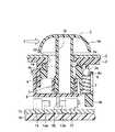
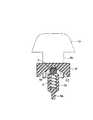
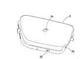
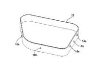
発明の実施の形態を図面を参照して説明すると、図1は本発明の実施形態例に係るスライド操作型スイッチ装置の非操作時の断面図、図2は該スイッチ装置のスライド操作時の断面図、図3は該スイッチ装置の構成要素である弾発力付与手段とカム部との係合状態を示す説明図、図4は該スイッチ装置の構成要素である操作体の斜視図、図5は該スイッチ装置の構成要素である化粧パネルの斜視図、図6は該スイッチ装置の構成要素である上ケースの斜視図、図7は該上ケースの底面側の斜視図、図8は該スイッチ装置の構成要素である一対のスライダの斜視図、図9は該スイッチ装置の構成要素であるホルダの斜視図、図10は該スイッチ装置の構成要素であるスイッチ素子群の斜視図、図11は該スイッチ装置の構成要素である下ケースの斜視図である。 An embodiment of the invention will be described with reference to the drawings. FIG. 1 is a cross-sectional view of a slide operation type switch device according to an embodiment of the present invention when not operated, and FIG. 2 is a cross section of the switch device during a slide operation. FIG. 3 is an explanatory view showing an engagement state between a resilient force applying means and a cam part as a component of the switch device, FIG. 4 is a perspective view of an operating body as a component of the switch device, and FIG. Is a perspective view of a decorative panel that is a component of the switch device, FIG. 6 is a perspective view of an upper case that is a component of the switch device, FIG. 7 is a perspective view of the bottom side of the upper case, and FIG. FIG. 9 is a perspective view of a holder that is a component of the switch device, FIG. 10 is a perspective view of a switch element group that is a component of the switch device, and FIG. Lower case which is a component of the switch device It is a perspective view.
これらの図に示すスライド操作型スイッチ装置は、搭乗者の腰まわりにフィットするようにシート面の形状が調整可能な車載機器の操作スイッチとして用いられるランバースイッチに本発明を適用した場合の例である。このスライド操作型スイッチ装置は、操作ノブ1aおよび軸部1bを有して4方向(互いに直交する2直線方向)へスライド操作可能な操作体1と、開口2aを開設した化粧パネル2と、開口2aと同形状の開口3aを開設して底面側にカム部3e,3f等を突設した上ケース3と、操作体1の軸部1bにスナップ結合された上スライダ4および下スライダ5と、上ケース3の底面側に固定されて該上ケース3との間に一対のスライダ4,5を配置させているホルダ6と、上スライダ4に保持されているコイルばね7と、下スライダ5に保持されているコイルばね8と、各コイルばね7,8の先端にそれぞれ配置されている球体9,10と、4個のスイッチ素子11〜14や図示せぬ回路部品を実装しているプリント回路基板15と、上ケース3にスナップ結合されて両スライダ4,5やホルダ6およびプリント回路基板15等を収納している下ケース16とによって主に構成されている。 The slide operation type switch device shown in these figures is an example in which the present invention is applied to a lumbar switch used as an operation switch of an in-vehicle device whose seat surface shape can be adjusted so as to fit around a passenger's waist. is there. This slide operation type switch device includes an
操作体1は前記開口3aに規制されて互いに直交する2直線方向へスライド操作可能であり、図4に示すように、この操作体1は、手指にてスライド操作しやすい形状に形成された操作ノブ1aと、この操作ノブ1aから下方へ突設された四角柱状の軸部1bとからなる。軸部1bの略平行な二つの外壁面の上部にはそれぞれ係合段部1cが形成されており、残り二つの外壁面の下部にはそれぞれ係合段部1dが形成されている。 The operating
図5に示すように、化粧パネル2の上面には操作体1のスライド操作を妨げないように略十字形の開口2aが開設されており、この開口2a内に操作体1の軸部1bが挿通される。また、化粧パネル2の側面の下部には複数箇所に係止孔2bが開設されており、これら係止孔2b内に上ケース3の係合突起3bを嵌入させるというスナップ結合によって、化粧パネル2は上ケース3に被着される。化粧パネル2は省略することも可能な部材であるが、このような化粧パネル2を取り付けることにより、上ケース3の形状のバリエーションを減らして製品コストを低減することができる。すなわち、図示せぬ回路部品の種類や実装位置が異なっても対応できるように上ケース3を汎用性の高い形状に設計しておき、用途に応じて上ケース3を覆う化粧パネル2のみを変更するようにすれば、複数種類の製品に共通の上ケース3を使用することができるため、製品コストを低減するうえで有効となる。 As shown in FIG. 5, a substantially
図6に示すように、上ケース3の上面には化粧パネル2の開口2aと合致する位置に略十字形の開口3aが開設されており、この開口3a内に操作体1の軸部1bが挿通される。上ケース3の側面の上部には化粧パネル2の係止孔2bに嵌入される係合突起3bが複数箇所に突設されており、また、上ケース3の側面の下部には下ケース16の係合突起16aを嵌入させるための係止孔3cが複数箇所に開設されている。一方、図7に示すように、上ケース3の底面には、上スライダ4のスライド移動を案内するガイド壁3dと、球体9の摺動面となる略V字形状のカム面C1が形成されたカム部3eと、球体10の摺動面となる略V字形状のカム面C2が形成されたカム部3fと、ホルダ6を固定するための複数本のねじ止めピン3gとが突設されている。また、カム面C1の中央部には凹段部3hが形成されており、カム面C2の中央部には凹段部3iが形成されている(図3参照)。これら凹段部3h,3iは、そこから球体9,10が離脱する際にクリック感触を生起させるためのものである。なお、カム部3eとカム部3fは互いに直交する平面に沿って起立しており、かつ、カム部3fの起立する平面に対して直交する向きにガイド壁3dが延びている。 As shown in FIG. 6, a substantially
図8に示すように、上スライダ4には、コイルばね7を収納する筒状のばね保持部4aと、ばね保持部4aの下方へ延出された駆動片4bと、操作体1の軸部1bが挿通される長孔4cと、この軸部1bの係合段部1cにスナップフィットして摺動可能に係合する一対のフック部4dと、上ケース3のガイド壁3dに摺接可能な一対の突条部4eとが設けられており、突条部4eの延伸方向は長孔4cの長手方向に対して直交している。この上スライダ4は、長孔4c内に操作体1の軸部1bを挿通していきフック部4dを係合段部1cに係合させることによって、長孔4cの長手方向に沿って摺動可能な状態で軸部1bにスナップ結合される。その際、軸部1bが長孔4cの長手方向に沿う両端部まで移動したときも、係合段部1cがフック部4dから外れないような位置関係に設定されている。また、この上スライダ4は、上ケース3とホルダ6との間に組み込まれて突条部4eが上ケース3のガイド壁3dに摺接すると共に、コイルばね7の弾発力によって球体9がカム部3eのカム面C1に弾接し、駆動片4bはホルダ6の開口6bを貫通してスイッチ素子11,12の間に配置される。したがって、この上スライダ4は、操作体1が長孔4cの長手方向に沿ってスライド移動しても追動しないが、操作体1が突条部4eの延伸方向に沿ってスライド移動すると、ガイド壁3dに案内されながら該操作体1と一体的にスライド移動し、それに伴い球体9がカム面C1に対し摺動してコイルばね7の弾発力が変化すると共に、スライド移動方向に応じて駆動片4bがスイッチ素子11または12を押圧駆動できるようになっている。 As shown in FIG. 8, the
図8に示すように、下スライダ5には、コイルばね8を収納する筒状のばね保持部5aと、ばね保持部5aの下方へ延出された駆動片5bと、操作体1の軸部1bが挿通される長孔5cと、この軸部1bの係合段部1dにスナップフィットして摺動可能に係合する一対のフック部5dと、ホルダ6のガイド壁6aに摺接可能な一対の突条部5eとが設けられており、突条部5eの延伸方向は長孔5cの長手方向に対して直交している。この下スライダ5は、長孔5c内に操作体1の軸部1bを挿通していきフック部5dを係合段部1dに係合させることによって、長孔5cの長手方向に沿って摺動可能な状態で軸部1bにスナップ結合される。その際、軸部1bが長孔5cの長手方向に沿う両端部まで移動したときも、係合段部1dがフック部5dから外れないような位置関係に設定されている。また、この下スライダ5は、上ケース3とホルダ6との間で上スライダ4の下方に組み込まれて、突条部5eがホルダ6のガイド壁6aに摺接すると共に、コイルばね8の弾発力によって球体10がカム部3fのカム面C2に弾接し、駆動片5bはホルダ6の開口6cを貫通してスイッチ素子13,14の間に配置される。したがって、この下スライダ5は、操作体1が長孔5cの長手方向に沿ってスライド移動しても追動しないが、操作体1が突条部5eの延伸方向に沿ってスライド移動すると、ガイド壁6aに案内されながら該操作体1と一体的にスライド移動し、それに伴い球体10がカム面C2に対し摺動してコイルばね8の弾発力が変化すると共に、スライド移動方向に応じて駆動片5bがスイッチ素子13または14を押圧駆動できるようになっている。なお、上スライダ4と下スライダ5はそれぞれの長孔4c,5cの長手方向を直交させているので、上スライダ4が操作体1と一体的にスライド移動する方向(突条部4eの延伸方向)と、下スライダ5が操作体1と一体的にスライド移動する方向(突条部5eの延伸方向)とは、互いに直交している。 As shown in FIG. 8, the
図9に示すように、ホルダ6には、下スライダ5のスライド移動を案内するガイド壁6aと、上スライダ4の駆動片4bを貫通させるための開口6bと、下スライダ5の駆動片5bを貫通させるための開口6cと、上ケース3のねじ止めピン3gを挿通して固定される複数の円筒部6dとが設けられている。このホルダ6は、円筒部6dに挿通したねじ止めピン3gに図示せぬ取付ねじを螺着することによって、各円筒部6dが各ねじ止めピン3gに締結固定される。 As shown in FIG. 9, the
図10に示すように、プリント回路基板15上に実装されているスイッチ素子11〜14はいずれもプッシュタイプのスイッチ素子であり、スイッチ素子11,12がそれぞれの被押圧部11a,12aを対向させて配設されており、スイッチ素子13,14がそれぞれの被押圧部13a,14aを対向させて配設されている。そして、被押圧部11aと被押圧部12aとの間に上スライダ4の駆動片4bが配置され、上スライダ4が操作体1と一体的にスライド移動すると、その移動方向に応じて駆動片4bが被押圧部11a,12aを選択的に押し込んでスイッチ素子11やスイッチ素子12を作動させるようになっている。同様に、被押圧部13aと被押圧部14aとの間に下スライダ5の駆動片5bが配置され、下スライダ5が操作体1と一体的にスライド移動すると、その移動方向に応じて駆動片5bが被押圧部13a,14aを選択的に押し込んでスイッチ素子13やスイッチ素子14を作動させるようになっている。 As shown in FIG. 10, the switch elements 11 to 14 mounted on the printed
図11に示すように、下ケース16の側面には係合突起16aと位置決め用のボス16bがそれぞれ複数箇所に突設されている。この下ケース16は、ボス16bで位置決めしつつ、各係合突起16aを上ケース3の対応する係止孔3c内に嵌入させるというスナップ結合を行うことによって上ケース3の底面側に被着され、これら両ケース3,16によって覆われる空間内に両スライダ4,5やホルダ6およびプリント回路基板15等が配設される。 As shown in FIG. 11, on the side surface of the
次に、このように構成されたスライド操作型スイッチ装置の動作を、主に図1と図2を参照しつつ説明する。 Next, the operation of the slide operation type switch device configured as described above will be described mainly with reference to FIGS.
操作体1に操作力が付与されていない非操作時には、球体9がコイルばね7の弾発力によってカム面C1の凹段部3hに入り込んで保持されているため、上スライダ4は中立位置に保持されて駆動片4bがスイッチ素子11,12の中間に位置しており、同様に球体10がコイルばね8の弾発力によってカム面C2の凹段部3iに入り込んで保持されているため(図3参照)、下スライダ5は中立位置に保持されて駆動片5bがスイッチ素子13,14の中間に位置している。つまり、上スライダ4がスライド移動してカム面C1に対する球体9の弾接位置が凹段部3hから離れるほどコイルばね7が圧縮されて弾発力が増大し、同様に下スライダ5がスライド移動してカム面C2に対する球体10の弾接位置が凹段部3iから離れるほどコイルばね8が圧縮されて弾発力が増大するので、両スライダ4,5に操作力が付与されていないときには、球体9,10はそれぞれ凹段部3h,3iに入り込んで保持される。したがって、操作体1の軸部1bは、上スライダ4の長孔4cの略中央で、かつ下スライダ5の長孔5cの略中央に位置しており、この位置は開口2aや開口3aの略中央に相当する。図1は、かかる非操作時の状態を示している。 When no operating force is applied to the
この状態でユーザが操作ノブ1aを図1の右方向へスライド操作すると、この操作方向は上スライダ4の長孔4cの長手方向に沿う方向なので、上スライダ4には操作力が付与されないが、下スライダ5は長孔5cの周縁部が操作体1の軸部1bによって操作方向へ押し込まれる。そのため、上スライダ4はスライド移動しないが、下スライダ5は図2に示すようにスライド移動し、それに伴い駆動片5bが被押圧部13aを押圧駆動してスイッチ素子13を作動させるので、このスイッチ素子13から出力される信号によって、操作体1が図1の右方向へスライド操作されたことを検出することができる。また、図1の状態から図2の状態へ至る過程で、球体10はまず凹段部3iから離脱してクリック感触を生起した後、カム面C2の傾斜に沿って凹段部3iから離れていき、下スライダ5に保持されているコイルばね8はカム部3fによって徐々に圧縮されていく(図3参照)。したがって、ユーザは、操作体1を図1の右方向へスライドさせたことにより所要のスイッチング操作が行えたことを、手指に伝達されるクリック感触によって感得することができる。 When the user slides the
また、図2に示す状態で操作ノブ1aに対する操作力Fが取り除かれると、圧縮されていたコイルばね8の弾発力によって球体10がカム面C2の凹段部3iへ入り込もうとするので、下スライダ5は逆向きにスライド移動して操作体1の軸部1bを押し戻す。そして、球体10が凹段部3iへ入り込んだ時点で、下スライダ5および操作体1はそれぞれの中立位置に保持され、スイッチ素子13に対する駆動片5bの押圧駆動力も除去されるので、図1に示す状態に自動復帰する。 Further, when the operating force F on the operating
また、図1に示す状態でユーザが操作ノブ1aを同図左方向へスライド操作した場合には、下スライダ5が操作方向へスライド移動して駆動片5bが被押圧部14aを押圧駆動するので、スイッチ素子14から検出信号が出力され、このときもクリック感触によってスイッチング操作が確認できる。つまり、下スライダ5を図1の左右方向(上スライダ4の長孔4cの長手方向)へスライド移動させることによって、2種類のスイッチング操作が行える。 When the user slides the
同様に、ユーザが操作ノブ1aを図1の紙面と直交する方向(下スライダ5の長孔5cの長手方向)へスライド操作した場合には、下スライダ5は操作力が付与されないため移動しないが、上スライダ4は長孔4cの周縁部が操作体1の軸部1aに押し込まれるためスライド移動し、移動方向に応じて駆動片4bが被押圧部11a,12aを選択的に押圧駆動する。したがって、スイッチ素子13,14を選択的に作動させて検出信号を出力させることができると共に、かかる2種類のスイッチング操作を、球体9が凹段部3hから離脱する際に生起されるクリック感触によって感得することができる。 Similarly, when the user slides the
このように本実施形態例に係るスライド操作型スイッチ装置では、上スライダ4と下スライダ5が互いに直交する方向へ摺動可能な状態で操作体1の軸部1bにスナップ結合されるため、組立時にこれら両スライダ4,5と操作体1を所要の係合関係を満足しつつ容易に連結することができ、軸部1bに抜け止め部材を取り付ける必要もなくなる。しかも、上スライダ4のスライド移動を案内するガイド壁3dを設けた上ケース3と、下スライダ5のスライド移動を案内するガイド壁6aを設けたホルダ6との間に、軸部1bに取り付けた状態の両スライダ4,5を配置させる構成にしてあるので、上ケース3とホルダ6とを一体化した段階で、各スライダ4,5をそれぞれ所定方向へ円滑にスライド移動できて操作体1が脱落する虞もないユニット品が得られる。それゆえ、このスイッチ装置は組立作業性に優れていると共に、操作体1の軸部1bと各スライダ4,5との間にガタが生じにくいため、良好な操作性が期待できる。さらに、操作体1が軸部1bと両スライダ4,5のスナップ結合部分の凹凸によってガイドされているので、操作体1をガタなくスムーズに移動させることができ、スナップ結合部分に抜け止め機能とガイド機能の両方をもたせることができる。 As described above, in the slide operation type switch device according to the present embodiment, the
また、本実施形態例に係るスライド操作型スイッチ装置では、上スライダ4や下スライダ5に保持されているコイルばね7,8の弾発力によって球体9,10を略V字形状のカム面C1,C2に常時弾接させ、その弾接位置がカム面C1,C2の中央部(凹段部3h,3i)から離れるほど弾発力が増大するように構成してあるので、スライド移動させた上スライダ4や下スライダ5や操作体1等を中立位置へ確実に自動復帰させることができる。すなわち、復帰ばねとして安価で小さなコイルばね7,8を使用できる構成になっているため、大きくて形状が複雑な復帰ばねを組み込む必要がなく、それゆえスイッチ装置全体の平面的な大きさを抑えた小型化が容易で、部品コストも低減しやすい。しかも、各スライダ4,5の球体9,10がカム面C1,C2の中央部(凹段部3h,3i)から離脱する際にクリック感触が生起されるため、クリック機構を別途設ける必要がなく、スイッチング操作時にクリック感触がユーザに伝達される使い勝手のよいスイッチ装置を安価に実現することができる。なお、カム面C1,C2を有するカム部3e,3fは、ガイド壁3dなどと同じく上ケース3の底面に突設されているので、カム面C1,C2を得るために専用の部材を追加する必要はない。 Further, in the slide operation type switching device according to the present embodiment, the
また、本実施形態例に係るスライド操作型スイッチ装置は、上スライダ4の駆動片4bを挟んで対向する位置にスイッチ素子11,12を設置し、かつ下スライダ5の駆動片5bを挟んで対向する位置にスイッチ素子13,14を設置する構成にしてあるため、各スライダ4,5の近傍に複数のスイッチ素子11〜14を集約して配設することができ、この点からもスイッチ装置全体の平面的な大きさを抑えた小型化が図りやすくなっている。 Further, the slide operation type switch device according to the present embodiment is provided with the
なお、上述した実施形態例では、操作体1が縦横4方向にスライド操作可能なスイッチ装置について説明したが、開口2aおよび開口3aの形状を45度間隔の放射形状とすれば、操作体1が長孔4c,5cの長手方向と約45度の角度をなす斜め方向へもスライド操作可能な構成にすることもできる。すなわち、かかる斜め方向へのスライド操作に伴い、上スライダ4と下スライダ5は共にスライド移動してそれぞれ対応するスイッチ素子を作動させるので、こうして作動される2個のスイッチ素子の組み合わせからさらに4種類のスイッチング操作が可能であり、それゆえ操作方向に応じて計8種類のスイッチング操作が行えることとなる。 In the above-described embodiment, the switch device is described in which the
また、上述した実施形態例では、車載用のランバースイッチに本発明を適用した場合について説明したが、操作体が多方向へスライド操作可能な他のスライド操作型スイッチ装置にも本発明を適用できることは言うまでもない。 In the above-described embodiment, the case where the present invention is applied to a vehicle-mounted lumbar switch has been described. However, the present invention can also be applied to other slide operation type switch devices in which an operation body can be slid in multiple directions. Needless to say.
1 操作体
1a 操作ノブ
1b 軸部
2 化粧パネル
3 上ケース(第1の固定部材)
3a 開口
3d ガイド壁
3e,3f カム部
3h,3i 凹段部
4 上スライダ
4a,5a ばね保持部(筒状部)
4b,5b 駆動片(駆動部)
4c,5c 長孔
4e,5e 突条部
5 下スライダ
6 ホルダ(第2の固定部材)
6a ガイド壁
7,8 コイルばね
9,10 球体
11,12,13,14 スイッチ素子
15 プリント回路基板
16 下ケース
C1,C2 カム面
DESCRIPTION OF
4b, 5b Drive piece (drive unit)
4c, 5c
Claims (6)
Translated fromJapanese前記操作体のスライド操作に連動する前記上スライダおよび/または前記下スライダの前記スライド移動に伴って前記カム面に対する前記弾発力付与手段の弾接位置が変化し、その弾接位置が該カム面の中央部から離れるほど弾発力が増大するように構成したことを特徴とするスライド操作型スイッチ装置。An operating knob and an operating body having a shaft portion projecting downward from the operation knob; and an upper slider that engages with the shaft portion and is slidable in a first linear direction perpendicular to the projecting direction of the shaft portion; A lower slider that engages with the shaft portion and is slidable in a projecting direction of the shaft portion and a second linear direction perpendicular to the first linear direction, and an elastic force held by each of the pair of sliders. A force generating means; a plurality of switch elements individually operated by the pair of sliders; a casing having an opening through which the shaft portion is inserted and housing the pair of sliders and the plurality of switch elements; A cam portion having a substantially V-shaped cam surface which is in a fixed relationship with the casing and is in constant contact with the elastic force applying means,
The elastic contact position of the elastic force applying means with respect to the cam surface changes with the sliding movement of the upper slider and / or the lower slider interlocked with the slide operation of the operating body, and the elastic contact position is the cam position. A slide operation type switching device characterized in that the elastic force increases as the distance from the center of the surface increases.
The concave step portion is formed at a central portion of the cam surface according to any one of claims 1 to 5, and the elastic force applying means is detached from the concave step portion by a sliding operation of the operation body. A slide operation type switch device characterized in that a click feeling is generated when the operation is performed.
Priority Applications (2)
| Application Number | Priority Date | Filing Date | Title |
|---|---|---|---|
| JP2004286839AJP2006100188A (en) | 2004-09-30 | 2004-09-30 | Slide operation type switch device |
| GB0517814AGB2418779B (en) | 2004-09-30 | 2005-09-02 | Sliding operation switch |
Applications Claiming Priority (1)
| Application Number | Priority Date | Filing Date | Title |
|---|---|---|---|
| JP2004286839AJP2006100188A (en) | 2004-09-30 | 2004-09-30 | Slide operation type switch device |
Publications (1)
| Publication Number | Publication Date |
|---|---|
| JP2006100188Atrue JP2006100188A (en) | 2006-04-13 |
Family
ID=36239770
Family Applications (1)
| Application Number | Title | Priority Date | Filing Date |
|---|---|---|---|
| JP2004286839AWithdrawnJP2006100188A (en) | 2004-09-30 | 2004-09-30 | Slide operation type switch device |
Country Status (1)
| Country | Link |
|---|---|
| JP (1) | JP2006100188A (en) |
Cited By (1)
| Publication number | Priority date | Publication date | Assignee | Title |
|---|---|---|---|---|
| JP2015056254A (en)* | 2013-09-11 | 2015-03-23 | アルプス電気株式会社 | Input device |
- 2004
- 2004-09-30JPJP2004286839Apatent/JP2006100188A/ennot_activeWithdrawn
Cited By (1)
| Publication number | Priority date | Publication date | Assignee | Title |
|---|---|---|---|---|
| JP2015056254A (en)* | 2013-09-11 | 2015-03-23 | アルプス電気株式会社 | Input device |
Similar Documents
| Publication | Publication Date | Title |
|---|---|---|
| JP4624269B2 (en) | Multi-directional input device | |
| US6538639B1 (en) | Multi-direction input device for fetching a sensing signal corresponding to an amount of inclination of lever member | |
| JP4777911B2 (en) | Combined operation type input device | |
| JP4363155B2 (en) | Rotating / pressing operation type electronic component and electronic device using the same | |
| JP4624306B2 (en) | Multi-directional input device | |
| JP4089397B2 (en) | Multi-directional slide switch | |
| KR100477775B1 (en) | Multi-directional switching apparatus | |
| JP4317741B2 (en) | 4-way switch device | |
| JP2005138787A (en) | Steering switch device | |
| JP4832317B2 (en) | Combined operation type input device | |
| JP4564556B2 (en) | Push operation type switch device | |
| CN105405701B (en) | Multi-directional inputting device | |
| JP2006100188A (en) | Slide operation type switch device | |
| JP2006100200A (en) | Slide operation type switch device | |
| JP2006224860A (en) | Steering switch device | |
| JPH10302576A (en) | Control switch | |
| JP5006293B2 (en) | Slide operation mechanism and slide operation type switch device provided with the mechanism | |
| JP2006286328A (en) | Composite operation type input device | |
| JP2006286334A (en) | Multiple direction input device | |
| JP4710646B2 (en) | Operation button structure | |
| JP2006286331A (en) | Multiple direction input device | |
| JP2007128731A (en) | Slide operation type switch | |
| JP2006286335A (en) | Multiple direction input device | |
| JP5722738B2 (en) | Multifunctional electronic components | |
| JP2001325857A (en) | Multi-directional input device |
Legal Events
| Date | Code | Title | Description |
|---|---|---|---|
| A621 | Written request for application examination | Effective date:20061225 Free format text:JAPANESE INTERMEDIATE CODE: A621 | |
| A977 | Report on retrieval | Free format text:JAPANESE INTERMEDIATE CODE: A971007 Effective date:20090703 | |
| A131 | Notification of reasons for refusal | Free format text:JAPANESE INTERMEDIATE CODE: A131 Effective date:20090804 | |
| A761 | Written withdrawal of application | Free format text:JAPANESE INTERMEDIATE CODE: A761 Effective date:20090821 |