JP2006098771A - Focus detection device, imaging device, imaging system, and lens unit - Google Patents
Focus detection device, imaging device, imaging system, and lens unitDownload PDFInfo
- Publication number
- JP2006098771A JP2006098771AJP2004285164AJP2004285164AJP2006098771AJP 2006098771 AJP2006098771 AJP 2006098771AJP 2004285164 AJP2004285164 AJP 2004285164AJP 2004285164 AJP2004285164 AJP 2004285164AJP 2006098771 AJP2006098771 AJP 2006098771A
- Authority
- JP
- Japan
- Prior art keywords
- chromatic aberration
- lens
- lens unit
- light
- unit
- Prior art date
- Legal status (The legal status is an assumption and is not a legal conclusion. Google has not performed a legal analysis and makes no representation as to the accuracy of the status listed.)
- Pending
Links
Images


Classifications
- G—PHYSICS
- G02—OPTICS
- G02B—OPTICAL ELEMENTS, SYSTEMS OR APPARATUS
- G02B7/00—Mountings, adjusting means, or light-tight connections, for optical elements
- G02B7/28—Systems for automatic generation of focusing signals
- G02B7/34—Systems for automatic generation of focusing signals using different areas in a pupil plane
- G02B7/343—Systems for automatic generation of focusing signals using different areas in a pupil plane using light beam separating prisms
- G—PHYSICS
- G03—PHOTOGRAPHY; CINEMATOGRAPHY; ANALOGOUS TECHNIQUES USING WAVES OTHER THAN OPTICAL WAVES; ELECTROGRAPHY; HOLOGRAPHY
- G03B—APPARATUS OR ARRANGEMENTS FOR TAKING PHOTOGRAPHS OR FOR PROJECTING OR VIEWING THEM; APPARATUS OR ARRANGEMENTS EMPLOYING ANALOGOUS TECHNIQUES USING WAVES OTHER THAN OPTICAL WAVES; ACCESSORIES THEREFOR
- G03B17/00—Details of cameras or camera bodies; Accessories therefor
- G03B17/02—Bodies
- G03B17/12—Bodies with means for supporting objectives, supplementary lenses, filters, masks, or turrets
- G03B17/14—Bodies with means for supporting objectives, supplementary lenses, filters, masks, or turrets interchangeably
- G—PHYSICS
- G03—PHOTOGRAPHY; CINEMATOGRAPHY; ANALOGOUS TECHNIQUES USING WAVES OTHER THAN OPTICAL WAVES; ELECTROGRAPHY; HOLOGRAPHY
- G03B—APPARATUS OR ARRANGEMENTS FOR TAKING PHOTOGRAPHS OR FOR PROJECTING OR VIEWING THEM; APPARATUS OR ARRANGEMENTS EMPLOYING ANALOGOUS TECHNIQUES USING WAVES OTHER THAN OPTICAL WAVES; ACCESSORIES THEREFOR
- G03B3/00—Focusing arrangements of general interest for cameras, projectors or printers
- G—PHYSICS
- G03—PHOTOGRAPHY; CINEMATOGRAPHY; ANALOGOUS TECHNIQUES USING WAVES OTHER THAN OPTICAL WAVES; ELECTROGRAPHY; HOLOGRAPHY
- G03B—APPARATUS OR ARRANGEMENTS FOR TAKING PHOTOGRAPHS OR FOR PROJECTING OR VIEWING THEM; APPARATUS OR ARRANGEMENTS EMPLOYING ANALOGOUS TECHNIQUES USING WAVES OTHER THAN OPTICAL WAVES; ACCESSORIES THEREFOR
- G03B7/00—Control of exposure by setting shutters, diaphragms or filters, separately or conjointly
- G03B7/20—Control of exposure by setting shutters, diaphragms or filters, separately or conjointly in accordance with change of lens
- H—ELECTRICITY
- H04—ELECTRIC COMMUNICATION TECHNIQUE
- H04N—PICTORIAL COMMUNICATION, e.g. TELEVISION
- H04N23/00—Cameras or camera modules comprising electronic image sensors; Control thereof
- H04N23/60—Control of cameras or camera modules
- H04N23/67—Focus control based on electronic image sensor signals
- H04N23/672—Focus control based on electronic image sensor signals based on the phase difference signals
- H—ELECTRICITY
- H04—ELECTRIC COMMUNICATION TECHNIQUE
- H04N—PICTORIAL COMMUNICATION, e.g. TELEVISION
- H04N25/00—Circuitry of solid-state image sensors [SSIS]; Control thereof
- H04N25/60—Noise processing, e.g. detecting, correcting, reducing or removing noise
- H04N25/61—Noise processing, e.g. detecting, correcting, reducing or removing noise the noise originating only from the lens unit, e.g. flare, shading, vignetting or "cos4"
Landscapes
- Physics & Mathematics (AREA)
- General Physics & Mathematics (AREA)
- Engineering & Computer Science (AREA)
- Multimedia (AREA)
- Signal Processing (AREA)
- Optics & Photonics (AREA)
- Automatic Focus Adjustment (AREA)
- Focusing (AREA)
- Structure And Mechanism Of Cameras (AREA)
- Exposure Control For Cameras (AREA)
Abstract
Translated fromJapaneseDescription
Translated fromJapanese本発明は、焦点検出装置、撮像装置、撮像システム及びレンズユニットに関し、詳しくはオートフォーカス時の各種光源下でのピント精度の改善に関する。 The present invention relates to a focus detection device, an imaging device, an imaging system, and a lens unit, and more particularly to improvement of focus accuracy under various light sources during autofocus.
撮像レンズを通った光束をビームスプリッタで分割して、分割した光束の光軸を互いにずらし、2つの結像レンズで焦点検出センサに結像し、2像のずれからデフォーカス量を計算し、そのデフォーカス量に応じて撮像レンズを駆動し合焦させる、いわゆるTTL(Through The Lens)位相差検出型のオートフォーカスは、銀塩及びデジタル一眼レフカメラで広く行われている。 The light beam that has passed through the imaging lens is split by a beam splitter, the optical axes of the split light beams are shifted from each other, the two imaging lenses form an image on the focus detection sensor, and the defocus amount is calculated from the shift between the two images. The so-called TTL (Through The Lens) phase difference detection type autofocus, in which the imaging lens is driven and focused in accordance with the defocus amount, is widely performed in silver salt and digital single lens reflex cameras.
他の方式のオートフォーカスとしては、撮像素子に結像される被写体像の高周波成分を抽出し、撮像レンズを駆動しながらその高周波成分がもっとも高くなる位置を合焦位置とする、いわゆるコントラスト検出方式のオートフォーカスがビデオカメラなどで広く行われている。 Another method of autofocus is the so-called contrast detection method, which extracts the high-frequency component of the subject image formed on the image sensor and sets the position where the high-frequency component is highest while driving the imaging lens as the in-focus position. Autofocus is widely used with video cameras.
この2つのオートフォーカス方式を比較すると、位相差検出方式は2像のずれから直接にデフォーカス量を検知でき、1回の焦点検出動作で合焦させることが可能であるので、AF動作が非常に早くできるという長所があるが、撮影光束を分離するビームスプリッタや、AF結像光学系、焦点検出センサなどを撮像光学系とは別に持つ必要があるために、コストが高くなるという欠点がある。 Comparing the two autofocus methods, the phase difference detection method can detect the defocus amount directly from the deviation of the two images, and can be focused by one focus detection operation. However, there is a disadvantage that the cost is increased because it is necessary to have a beam splitter that separates the imaging light beam, an AF imaging optical system, a focus detection sensor, and the like separately from the imaging optical system. .
一方コントラスト検出方式では、特別なAF検出系を配置する必要がないので、コスト面でも有利であり、また、撮像面上で直接合焦状態の判定ができるので、ピント精度も良いと言う長所があるが、反面、位相差検出方式の様にデフォーカス量を直接に求める事ができず、撮像レンズを少しづつ動かして撮影画像の高周波成分を検出する動作を繰り返し行い、合焦位置を見つけ出す必要があるので、位相差検出方式に比べ、一般的に合焦速度が非常に遅くなるという欠点がある。 On the other hand, the contrast detection method is advantageous in terms of cost because it is not necessary to arrange a special AF detection system, and the focus state can be determined directly on the imaging surface, so that the focus accuracy is good. However, unlike the phase difference detection method, the defocus amount cannot be obtained directly, and it is necessary to find the in-focus position by repeatedly moving the imaging lens little by little to detect the high-frequency component of the captured image. Therefore, there is a drawback that the focusing speed is generally very slow compared to the phase difference detection method.
このため、早い合焦動作を重視する静止画の一眼レフカメラでは、TTL位相差検出方式が広く採用されているが、前述のコストアップという問題の他に、撮像系と焦点検出系が異なることで、以下の問題が生じる。 For this reason, TTL phase difference detection methods are widely used in single-lens reflex cameras that place importance on fast focusing operations. However, in addition to the above-described cost increase, the imaging system and the focus detection system are different. Thus, the following problems occur.
撮像系の分光感度特性は一般的な銀塩フィルムの場合では、人間の目の特性に合わせた色再現性を持たせるために、通常400〜650nm程度の光に対してもっとも高い感度を有している。一方CMOSなどの撮像素子の光電変換を行うためのシリコンフォトダイオードは、一般的には800nm程度に感度ピークを持っており、長波長側は1100nm程度まで感度を持っているが、色再現性を重視するために、感度を犠牲にして上記周波数範囲外の波長の光はフィルター等で遮断するようにしてある。 In the case of a general silver salt film, the spectral sensitivity characteristics of the imaging system usually have the highest sensitivity to light of about 400 to 650 nm in order to have color reproducibility that matches the characteristics of the human eye. ing. On the other hand, a silicon photodiode for performing photoelectric conversion of an image pickup device such as a CMOS generally has a sensitivity peak at about 800 nm and has a sensitivity up to about 1100 nm on the long wavelength side, but has color reproducibility. To emphasize this, light having a wavelength outside the above frequency range is blocked by a filter or the like at the expense of sensitivity.
一方、オートフォーカス検出用として用いられるセンサとしての光電変換素子は、同様に1100nm程度まで感度を持っているが、低輝度下でも合焦動作を行う場合があり、また、低輝度下で合焦動作ができない場合に、カメラ側から近赤外(700nm程度)の発光ダイオードからの光を被写体に照射するので、撮像系よりも100nm程度長波長領域まで感度を有するようにしている。 On the other hand, a photoelectric conversion element as a sensor used for autofocus detection similarly has a sensitivity up to about 1100 nm, but may perform a focusing operation even under low luminance, and may be focused under low luminance. When the operation cannot be performed, light from a near-infrared (about 700 nm) light emitting diode is irradiated to the subject from the camera side, so that sensitivity is provided to a wavelength region longer by about 100 nm than the imaging system.
図8(a)は撮像素子の分光感度及び、光源と補助光の分光特性を示す図であり、横軸は光の波長、縦軸は相対的エネルギー示す。同図において、B、G、Rは原色型撮像素子の青画素、緑画素、赤画素の各々の分光感度を示し、Fは蛍光灯、Lはフラッドランプ、Aは前述した発光ダイオード等の補助光の分光特性を示す。また、図8(b)は光の波長に対する撮像レンズの色収差による相対的なピント位置の変位を示す図であり、横軸は波長を、縦軸はピント位置の変位を示す。 FIG. 8A is a diagram illustrating the spectral sensitivity of the image sensor and the spectral characteristics of the light source and the auxiliary light. The horizontal axis indicates the wavelength of light and the vertical axis indicates the relative energy. In the same figure, B, G, and R indicate the spectral sensitivities of the blue, green, and red pixels of the primary color type image sensor, F is a fluorescent lamp, L is a flood lamp, and A is an auxiliary such as the above-described light emitting diode. The spectral characteristics of light are shown. FIG. 8B is a diagram showing the relative displacement of the focus position due to the chromatic aberration of the imaging lens with respect to the wavelength of light. The horizontal axis indicates the wavelength, and the vertical axis indicates the displacement of the focus position.
図8(a)に示すように、蛍光灯には620nmより長波長成分はほとんど含まれていないことに対し、フラッドランプでは長波長側になるほど、相対的エネルギーが強くなることが分かる。 As shown in FIG. 8A, it can be seen that the fluorescent lamp contains almost no longer wavelength component than 620 nm, whereas the flood lamp has a higher relative energy as the wavelength becomes longer.
一方、図8(b)のラインCから、波長に応じてピント位置の変位量が変化し、長波長側になるほど焦点距離が伸びる方向に大きくなることが分かる。 On the other hand, it can be seen from the line C in FIG. 8B that the amount of displacement of the focus position changes according to the wavelength, and the focal length increases in the longer wavelength side.
したがって、被写体を照明する光源が長波長成分の少ない蛍光灯の場合は、輝線ピークのある545nm付近が光源の分光分布の中心であるので、図8(b)で示す様に、レンズの焦点距離が短くなる方向であり、長波長成分の多いフラッドランプの時は、長波長成分になる程エネルギーが高くなるのでレンズの焦点距離が伸びる方向であるので、同じ位置に被写体があったとしても、結果として撮像面側でピントがずれてしまうと言う問題が生じる。 Therefore, in the case where the light source that illuminates the subject is a fluorescent lamp with a small long wavelength component, the vicinity of 545 nm where the bright line peak is located is the center of the spectral distribution of the light source, and as shown in FIG. In the case of a flood lamp with many long wavelength components, the energy increases as the long wavelength component increases, so the focal length of the lens increases, so even if there is a subject at the same position, As a result, there arises a problem that the focus is shifted on the imaging surface side.
この光源の分光特性により撮像系のピント位置がずれる問題に対応するために、光源の種類に応じてピント位置を補正するカメラが特許文献1、2により開示されている。 In order to cope with the problem that the focus position of the imaging system is shifted due to the spectral characteristics of the light source,
これらの発明では、分光感度の異なる2種類のセンサの出力を比較して光源の種類を判別し、判別した光源の種類に応じてピント位置の補正(つまり、フォーカスレンズ位置の補正)を行うことにより、光源の分光特性に起因するピントずれを補正する方法が開示されている。 In these inventions, the output of two types of sensors having different spectral sensitivities are compared to determine the type of light source, and the focus position is corrected (that is, the focus lens position is corrected) according to the determined type of light source. Discloses a method of correcting a focus shift caused by spectral characteristics of a light source.
しかしながら、上記特許文献1、2で開示されている自動焦点カメラでは、色収差に対するピント位置の補正量は固定値として扱われており、それをそのままレンズ交換式のオートフォーカスカメラに適用すると、レンズの差により色収差が異なる場合にはピント補正量に過不足が生じてしまう。 However, in the autofocus cameras disclosed in
本発明は上記問題点を鑑みてなされたものであり、レンズ交換式のTTL位相差検出方式のオートフォーカスカメラにおいて、異なるレンズを用いても、光源の種類によるピントずれを抑制した精度の良いオートフォーカスを実現することを目的とする。 SUMMARY OF THE INVENTION The present invention has been made in view of the above-described problems. In an autofocus camera using a TTL phase difference detection method with interchangeable lenses, even if different lenses are used, a highly accurate auto that suppresses the focus shift due to the type of light source. The purpose is to achieve focus.
上記目的を達成するために、本発明の焦点検出装置は、着脱可能なレンズユニットを透過した光束を2系統に分割し、各光束により形成される2つの画像間の位相差に基づいてデフォーカス量を検出する焦点検出手段と、前記レンズユニットの光の波長に応じた色収差に関する情報を取得する色収差情報取得手段と、光源色に基づく色収差の補正値を記憶する記憶手段と、前記レンズユニットを透過した光束の内、主に可視光領域を測光する第1の測光手段と、前記レンズユニットを透過した光束の内、主に可視光より長波長領域を測光する第2の測光手段と、前記第1と第2の測光手段の出力差に応じて、前記記憶手段から補正値を取得する補正値取得手段と、前記色収差情報取得手段により取得した色収差に関する情報と、前記補正値取得手段により取得した補正値とに応じて、前記自動焦点検出手段により検出したデフォーカス量を補正する補正手段とを有する。 In order to achieve the above object, the focus detection apparatus of the present invention divides a light beam transmitted through a detachable lens unit into two systems, and defocuses based on a phase difference between two images formed by each light beam. A focus detection means for detecting an amount; a chromatic aberration information acquisition means for acquiring information on chromatic aberration according to the wavelength of light of the lens unit; a storage means for storing a correction value of chromatic aberration based on a light source color; and the lens unit. A first photometric means for mainly measuring a visible light region in the transmitted light beam; a second photometric means for measuring a light wavelength region mainly longer than the visible light in the light beam transmitted through the lens unit; In accordance with the output difference between the first and second photometry means, correction value acquisition means for acquiring a correction value from the storage means, information on chromatic aberration acquired by the chromatic aberration information acquisition means, and the correction value acquisition Depending on the correction value acquired by the means, and a correcting means for correcting the defocus amount detected by the automatic focus detection means.
また、本発明の撮像装置は、複数種類のレンズユニットを着脱可能であって、上記焦点検出装置を有する。 In addition, the imaging apparatus of the present invention can attach and detach a plurality of types of lens units, and has the focus detection apparatus.
更に、本発明の撮像システムは、上記8焦点検出装置を有する撮像装置本体と、当該撮像装置本体に着脱可能なレンズユニットとからなる。 Furthermore, the imaging system of the present invention includes an imaging apparatus main body having the above eight focus detection apparatus and a lens unit that can be attached to and detached from the imaging apparatus main body.
更に、本発明のレンズユニットは撮像装置本体に装着して使用され、光の波長に応じた色収差に関する情報を記憶する記憶手段と、前記装着した撮像装置本体に対して、前記色収差に関する情報を送信する送信手段とを有する。 Furthermore, the lens unit of the present invention is used by being mounted on the image pickup apparatus main body, and stores information on chromatic aberration corresponding to the wavelength of light, and transmits information on the chromatic aberration to the mounted image pickup apparatus main body. Transmitting means.
本発明によれば、レンズ交換式のTTL位相差検出方式のオートフォーカスカメラにおいて、異なるレンズを用いても、光源の種類によるピントずれを抑制した精度の良いオートフォーカスを実現することができる。 According to the present invention, in an autofocus camera using a TTL phase difference detection method with interchangeable lenses, it is possible to realize a highly accurate autofocus in which focus deviation due to the type of light source is suppressed even if different lenses are used.
以下、添付図面を参照して本発明を実施するための最良の形態を詳細に説明する。ただし、本形態において例示される構成部品の寸法、形状、それらの相対配置などは、本発明が適用される装置の構成や各種条件により適宜変更されるべきものであり、本発明がそれらの例示に限定されるものではない。 The best mode for carrying out the present invention will be described below in detail with reference to the accompanying drawings. However, the dimensions, shapes, relative arrangements, and the like of the components exemplified in the present embodiment should be changed as appropriate according to the configuration of the apparatus to which the present invention is applied and various conditions. It is not limited to.
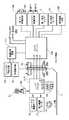
図1は本発明の実施の一形態に係る、一眼レフレックスカメラと該カメラに装着される交換レンズとによって成るオートフォーカスカメラシステムの概略構成を示す図であり、ここでは主に光学的な配置関係を示している。 FIG. 1 is a diagram showing a schematic configuration of an autofocus camera system including a single-lens reflex camera and an interchangeable lens attached to the camera according to an embodiment of the present invention. Here, mainly an optical arrangement is shown. Showing the relationship.
同図において、1はカメラ本体であり、その前面にはレンズユニット11が装着される。カメラ本体1内には、光学部品、機械部品、電気回路およびフィルム又はCCD等の撮像素子などが収納され、フィルムを用いた写真撮影又は、光電変換素子による画像撮影を行うことができる。2は主ミラーであり、ファインダー観察状態では撮影光路内に斜設され、撮影状態では撮影光路外に退避する。また、主ミラー2はハーフミラーとなっており、撮影光路内に斜設されているときは、後述する焦点検出ユニット26へ被写体からの光線の約半分を透過させる。 In the figure,
3は、ファインダー光学系を構成する、後述のレンズ12〜14の予定結像面に配置されたピント板であり、4はファインダー光路変更用のペンタプリズムである。5はアイピースであり、撮影者はこの窓からピント板3を観察することで、撮影画面を確認することができる。6と7はファインダー観察画面内の被写体輝度を測定するための第1の結像レンズと第1の測光センサ、30と31は同様に第2の結像レンズと第2の測光センサ、32は長波長側を遮蔽する光学フィルタ、33は可視光側を遮蔽する光学フィルタである。この第1の測光センサ7と第2の測光センサ31は内部に公知の対数圧縮回路を持っており、その出力は対数圧縮されたものとなる。
8はフォーカルプレーンシャッター、9は感光部材であり、銀塩フィルム又は、CCDやCMOS等の撮像素子が用いられる。25はサブミラーであり、主ミラー2とともに、ファインダー観察状態では撮影光路内に斜設され、撮影状態では撮影光路外に退避する。このサブミラー25は、斜設された主ミラー2を透過した光線を下方に折り曲げて、後述の焦点検出ユニット26の方に導くものである。 8 is a focal plane shutter, 9 is a photosensitive member, and a silver salt film or an image sensor such as a CCD or CMOS is used.
26は焦点検出ユニットであり、2次結像ミラー27、2次結像レンズ28、焦点検出ラインセンサ29や後述の焦点検出回路等から構成されている。2次結像ミラー27および2次結像レンズ28は焦点検出光学系を構成しており、レンズユニット11の2次結像面を焦点検出ラインセンサ29上に形成している。この焦点検出ユニット26はいわゆる位相差検出法によってレンズユニット11の焦点調節状態を検出し、その検出結果をレンズユニット11の焦点調節機構を制御する自動焦点調節装置へ送出する。 A
10はカメラ本体1とレンズユニット11との通信インターフェイスとなるマウント接点群である。 A
12〜14はレンズであり、1群レンズ(以下、フォーカシングレンズと記す)12は光軸上を前後に移動することで撮影画面のピント位置を調整するものであり、2群レンズ13は光軸上を前後に移動することでレンズユニット11の焦点距離を変更し、撮影画面の変倍を行うものであり、14は固定の3群レンズである。15は絞りである。16は駆動モータであり、自動焦点調節動作時にフォーカシングレンズ12を光軸方向に前後移動させるフォーカス駆動モータである。17は絞り15の開口径を変化させるための絞り駆動モータである。18は距離エンコーダーであり、フォーカシングレンズ12に取り付けられたブラシ19が摺動することで、該フォーカシングレンズ12の位置を読み取り、被写体距離に相当する信号を発生する。詳しくは、距離エンコーダ18とブラシ19および後述するレンズマイコン112は、ピント調節された後のフォーカシングレンズ12の位置を読み取り、該位置よりその時の被写体距離に換算した信号(被写体距離情報)を出力する被写体距離検出手段を構成している。
次に、図2を用いて、上記カメラシステムの回路構成について説明する。なお、図1と共通の構成要素には同じ符号を付している。 Next, the circuit configuration of the camera system will be described with reference to FIG. In addition, the same code | symbol is attached | subjected to the same component as FIG.
まず、カメラ本体1内の回路構成について説明する。 First, the circuit configuration in the
カメラマイコン100には、焦点検出回路105、第1測光センサ7、第2測光センサ31、シャッター制御回路107、モータ制御回路108および液晶表示回路111が接続されている。また、カメラマイコン100は、レンズユニット11内に配置されたレンズマイコン112とはマウント接点10を介して信号伝達を行う。 The
焦点検出回路105は、カメラマイコン100からの信号に従って焦点検出ラインセンサ29の積制御と読み出し制御を行い、それぞれの画素情報をカメラマイコン100に出力する。カメラマイコン100はこの情報をA/D変換し、位相差検出法による焦点調節状態の検出を行い、レンズマイコン112と信号のやりとりを行うことによって、レンズユニット11の焦点調節制御を行う。 The
シャッター制御回路107は、カメラマイコン100からの信号に従ってフォーカルプレンシャッター8を構成するシャッター先幕駆動マグネットMG−1およびシャッター後幕駆動マグネットMG−2の通電制御を行い、シャッター先幕および後幕を走行させ、露出動作を行う。モータ制御回路108は、カメラマイコン100からの信号に従ってモータMを制御することにより、主ミラー2及びサブミラー25のアップダウン、及びシャッターチャージなどを行う。 The
SW1は不図示のレリーズボタンの第1ストローク(半押し)操作でONし、測光やAF(自動焦点調節)などの撮影準備を開始させるスイッチである。SW2はレリーズボタンの第2ストローク(全押し)操作でONし、シャッター走行、すなわち露光動作を開始させるスイッチである。スイッチSW1及びSW2、また、その他不図示の操作部材である、ISO感度設定スイッチ、絞り設定スイッチ、シャッター速度設定スイッチなどの各スイッチの状態信号はカメラマイコン100が読み取る。 SW1 is a switch that is turned on by a first stroke (half-pressing) operation of a release button (not shown) and starts preparation for photographing such as photometry and AF (automatic focus adjustment). SW2 is a switch that is turned on by the second stroke (full press) operation of the release button and starts the shutter running, that is, the exposure operation. The
液晶表示回路111は、ファインダー内表示器24と外部表示器42をカメラマイコン100からの信号に従って制御する。 The liquid
次に、レンズユニット11内の電気回路構成について説明する。 Next, an electric circuit configuration in the
上述したように、カメラ本体1とレンズユニット11とはレンズマウント接点10を介して相互に電気的に接続される。このレンズマウント接点10は、レンズユニット11内のフォーカス駆動用モータ16および絞り駆動用モータ17の電源用接点である接点L0と、レンズマイコン112の電源用接点L1と、シリアルデータ通信を行うためのクロック用接点L2と、カメラ本体1からレンズユニット11へのデータ送信用接点L3と、レンズユニット11からカメラ本体1へのデータ送信用接点L4と、モータ用電源に対するモータ用グランド接点L5と、レンズマイコン112用電源に対するグランド接点L6とから構成されている。 As described above, the
レンズマイコン112は、レンズマウント接点10を介してカメラマイコン100と接続され、カメラマイコン100からの信号に応じてフォーカシングレンズ12を駆動するフォーカス駆動モータ16および絞り15を駆動する絞り駆動モータ17を動作させ、レンズユニット11の焦点調節と絞りを制御する。50と51は光検出器とパルス板であり、レンズマイコン112がパルス数をカウントすることによりピント調節(合焦動作)時のフォーカシングレンズ12の位置情報を得る。これにより、レンズユニット11の焦点調節を行うことができる。 The
18は前述した距離エンコーダーであり、ここで読み取られたフォーカシングレンズ12の位置情報はレンズマイコン112に入力され、ここで被写体距離情報に変換され、カメラマイコン100に伝達される。
次に、図3を用いて第1と第2の測光センサ7、31の分光特性について説明する。 Next, spectral characteristics of the first and second
同図において、横軸は光の波長を示し、縦軸は、最も高い分光感度を1として正規化した分光感度を示す。Aは第1と第2の測光センサ7、31の分光感度特性であり、Bは第1の測光センサ7の前に配置される光学フィルター32の分光感度特性であり、Cは第2の測光センサ31の前に配置される光学フィルター33の分光感度特性である。したがって、第1の測光センサ7は主に可視光領域の光を検出し、第2の測光センサ31は主に可視外の長波長領域の光を検出することが可能である。 In the figure, the horizontal axis indicates the wavelength of light, and the vertical axis indicates the spectral sensitivity normalized with the highest spectral sensitivity as 1. A is the spectral sensitivity characteristic of the first and second
次に、上記構成のカメラシステムのオートフォーカス動作について、図4のフローチャートを用いて説明する。 Next, the autofocus operation of the camera system configured as described above will be described with reference to the flowchart of FIG.
図2で示したカメラ本体1のスイッチSW1が押されると、ステップS101より動作を開始する。ここでは、カメラマイコン100は、焦点検出回路105を含む焦点検出ユニット26内の焦点検出ラインセンサ29の電荷蓄積を行い、結像された被写体像を読み取る。 When the switch SW1 of the
次のステップS102では取得した2象のずれから、公知の位相差による焦点検出方法でデフォーカス量の演算を行う。ここでは、焦点検出ラインセンサ29上の2像のずれ(bit数)に対して、センサーピッチ[mm]とオートフォーカス系の基線長などの光学係数を掛け合わせることにより、撮影像面上でのデフォーカス量(mm)を求める。 In the next step S102, the defocus amount is calculated from the acquired displacement between the two images by a known focus detection method using a phase difference. Here, by multiplying the shift (number of bits) of the two images on the focus
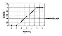
次のステップS103では、第1の測光センサ7および第2の測光センサ31の測光値を読み出し、ステップS104において第2の測光センサ31の測光値から第1の測光センサ7の測光値を差分し、得られた差分に応じて図6のテーブルから補正係数を読み出す。 In the next step S103, the photometric values of the first photometric sensor 7 and the second
図6に示すデータはカメラマイコン100の中の不図示のROM内に記憶されており、横軸は第1と第2の測光センサ7、31の輝度差に対応し、縦軸は両センサの輝度差に応じた補正係数を示す。図6に示す例では、たとえば第1の測光センサ7と第2の測光センサ31との輝度差が3段である場合、補正係数は0.5となる。このように、主に長波長領域の光を検出する第2の測光センサ31の出力が小さくなるほど、光源がより短波長領域の光を多く含んでいるため、補正係数もより大きくなる。 The data shown in FIG. 6 is stored in a ROM (not shown) in the
次のステップS105ではレンズマイコン112に対して色収差量の送信を前述のシリアル通信ラインLCK,LDO,LDIを介してレンズマイコン112に対して指示する。この通信を受けてレンズマイコン112は通信の内容を解析し、その指令が、色収差量を問い合わせる通信であった場合は、現在の焦点距離及びフォーカス位置に応じた色収差データをマイコン112内の不図示のROMテーブルから読み出し、シリアル通信ラインLCK,LDO,LDIを介してカメラマイコン100に返送する。 In the next step S105, the
図7は、35〜70mmのズームレンズがレンズユニット11としてカメラ1に取り付けられている場合に、ROM内のテーブルに記憶されている色収差データの例であり、白昼光でのAF位置に対して、短波長領域の光を多く照射する光源として代表的な蛍光灯下でのピントのずれ量(重心波長の違いによる色収差量に合致する)を示すデータであり、レンズの各焦点距離における被写体距離でのピントのずれ量を示している。このようなテーブルから焦点距離と被写体距離(フォーカシングレンズ12の位置をエンコーダー18で読み取ったもの)をアドレスとして、ROM内からずれ量を読み出す。なお、図7に示すような色収差データは各交換レンズユニットがそれぞれ有しており、基本的には光学設計上決定される値であるので、ROMに固定的に記憶すればよいが、製造上の誤差を考慮して製造時にピントのずれ量を測定して、EEPROMやフラッシュROMなどの書き込み可能な記憶手段に記憶させてもよい。 FIG. 7 is an example of chromatic aberration data stored in a table in the ROM when a 35 to 70 mm zoom lens is attached to the
また、ピント移動量を焦点距離と被写体位置をパラメータとした、多項式で近似させ、その多項式の係数を同様にROMまたはEEPROM、フラッシュROMなどに記憶しておき、ピントずれ量データを使用する際に、焦点距離と被写体距離を元に演算で求める様にしてもよい。 Also, when the focus shift amount is approximated by a polynomial with the focal length and subject position as parameters, the coefficients of the polynomial are similarly stored in a ROM, EEPROM, flash ROM, or the like, and when the focus shift amount data is used. The calculation may be performed based on the focal length and the subject distance.
次のステップS106では、ステップS105で取得したレンズの色収差データに対して、ステップS104で求めた補正係数を乗じてピント補正量を演算し、ステップS107ではステップS102で求めたデフォーカス量にピント補正量を加算して、最終的なデフォーカス量を演算する。つまりデフォーカス量をdef、色収差量をc、ピント補正係数をkとすると、
最終デフォーカス量=k×c+defIn the next step S106, the lens chromatic aberration data obtained in step S105 is multiplied by the correction coefficient obtained in step S104 to calculate a focus correction amount. In step S107, the defocus amount obtained in step S102 is focused. The amount is added to calculate the final defocus amount. In other words, if the defocus amount is def, the chromatic aberration amount is c, and the focus correction coefficient is k,
Final defocus amount = k × c + def
で求める事ができる。
次のステップS108ではこのデフォーカス量が所望の範囲内、たとえば(1/4)Fδ以内(F:レンズの絞り値、δ:定数:20um、したがってF2.0のレンズの開放絞りでは10um)であるならば合焦と判断し、オートフォーカス動作を終了し、1/4Fδより大きければ、ステップS109でこのデフォーカス量を前述のシリアル通信ラインLCK,LDO,LDIを介してレンズマイコン112に対して送信し、レンズ駆動を指令する。この指令を受けてレンズマイコン112は、受信したデフォーカス量に応じてフォーカス駆動モータ16の駆動方向を決定し、指令されたデフォーカス量に応じてフォーカス駆動モータを駆動し、ステップS101に戻り、合焦状態になるまで前述の動作を繰り返す。You can ask for it.
In the next step S108, this defocus amount is within a desired range, for example, within (1/4) Fδ (F: lens aperture value, δ: constant: 20 μm, and therefore 10 μm for the open aperture of F2.0 lens). If there is, it is determined that the subject is in focus, and the autofocus operation is terminated. If it is greater than 1 / 4Fδ, the defocus amount is sent to the
ステップS108で合焦と判断されるとステップS110に移り、レリーズ開始スイッチSW2の判定を行う。オンの場合は、図5のステップS201に進んで、撮影動作を行い、オフの場合はAF処理を終了する。 If it is determined in step S108 that the subject is in focus, the process proceeds to step S110, and the release start switch SW2 is determined. If it is on, the process proceeds to step S201 in FIG. 5 to perform a photographing operation, and if it is off, the AF process is terminated.
次に図5を用いて撮影動作を説明する。 Next, the photographing operation will be described with reference to FIG.
前述のオートフォーカス動作が終了し、図2のレリーズ開始スイッチSW2がオン状態の場合は、ステップS201で、カメラマイコン100は可視光側波長の光を測光する第1の測光センサ7の測光値から、被写体輝度BVを求め、設定されたISO感度SVと加算して露出値EVを求め、公知の方法で、絞り値AVおよびシャッター速度TVを算出する。なお、この測光動作は、図4のステップS110の判定前に行っても良い。 When the above-described autofocus operation is finished and the release start switch SW2 of FIG. 2 is in the on state, in step S201, the
次のステップS202では、主ミラー2を跳ね上げて撮影光路から退避させると同時に、カメラマイコン100はレンズマイコン112に対してステップS201で決定した絞り値AVに絞り込む様に指示し、レンズマイコン112はその指令を受けて絞り15を調節し、その後、主ミラー2が撮影光路から完全に退避するとステップS203でカメラマイコン100はシャッター先幕駆動マグネットMG−1に通電し、フォーカルプレーンシャッター8の開放動作を開始させる。 In the next step S202, the
所定のシャッター開放時間が経過するとステップS204へ進み、カメラマイコン100はシャッター後幕駆動マグネットMG−2に通電し、フォーカルプレーンシャッター8の後幕を閉じて露出を終了しステップS205で主ミラー2をダウンさせ、撮影を終了する。 When the predetermined shutter opening time elapses, the process proceeds to step S204, where the
上記の通り、本実施の形態によれば、カメラ本体に対しレンズユニットが交換可能である場合に、レンズユニットからそのレンズユニット固有の色収差データを取得し、更に、光源色に応じた補正量を取得し、取得したレンズユニット固有の色収差データと補正量とにより、デフォーカス量を補正するため、異なるレンズユニットが装着された場合であっても、装着されたレンズユニットに適したデフォーカス量の補正を行うことが可能となる。 As described above, according to the present embodiment, when the lens unit is replaceable with respect to the camera body, the chromatic aberration data specific to the lens unit is acquired from the lens unit, and the correction amount corresponding to the light source color is further obtained. Since the defocus amount is corrected based on the acquired chromatic aberration data and correction amount specific to the lens unit, even if a different lens unit is mounted, the defocus amount suitable for the mounted lens unit Correction can be performed.
なお、上記実施の形態では、レンズユニットがレンズユニット特有の色収差データを保持する場合について説明したが、カメラ本体に装着可能なレンズユニットの種類が限られている場合には、レンズユニットの種類毎に、カメラ本体で色収差データを保持しておき、装着されたレンズユニットからはその種類とフォーシングレンズの位置とを取得することにより、対応する色収差データを読み出すようにしても良い。 In the above-described embodiment, the case where the lens unit holds the chromatic aberration data peculiar to the lens unit has been described. However, when the types of lens units that can be attached to the camera body are limited, each lens unit type In addition, the chromatic aberration data may be held in the camera body, and the corresponding chromatic aberration data may be read out by acquiring the type and the position of the forcing lens from the mounted lens unit.
1 カメラ本体
6 第1の結像レンズ
7 第1の測光センサ
11 レンズユニット
12 フォーカシングレンズ
26 焦点検出ユニット
27 2次結像ミラー
28 2次結像レンズ
29 焦点検出ラインセンサ
30 第2の結像レンズ
31 第2の測光センサ
32、33 光学フィルタ
100 カメラマイコン
112 レンズマイコンDESCRIPTION OF
Claims (8)
Translated fromJapanese前記レンズユニットの光の波長に応じた色収差に関する情報を取得する色収差情報取得手段と、
光源色に基づく色収差の補正値を記憶する記憶手段と、
前記レンズユニットを透過した光束の内、主に可視光領域を測光する第1の測光手段と、
前記レンズユニットを透過した光束の内、主に可視光より長波長領域を測光する第2の測光手段と、
前記第1と第2の測光手段の出力差に応じて、前記記憶手段から補正値を取得する補正値取得手段と、
前記色収差情報取得手段により取得した色収差に関する情報と、前記補正値取得手段により取得した補正値とに応じて、前記自動焦点検出手段により検出したデフォーカス量を補正する補正手段と
を有することを特徴とする焦点検出装置。A focus detection unit that divides a light beam transmitted through the detachable lens unit into two systems and detects a defocus amount based on a phase difference between two images formed by each light beam;
Chromatic aberration information acquisition means for acquiring information relating to chromatic aberration according to the wavelength of light of the lens unit;
Storage means for storing a correction value of chromatic aberration based on the light source color;
A first photometric means for photometrically measuring the visible light region of the light beam transmitted through the lens unit;
A second photometric means for measuring light in a longer wavelength region than visible light, out of the luminous flux transmitted through the lens unit;
Correction value acquisition means for acquiring a correction value from the storage means according to an output difference between the first and second photometry means;
Correction means for correcting a defocus amount detected by the automatic focus detection means in accordance with information on chromatic aberration acquired by the chromatic aberration information acquisition means and a correction value acquired by the correction value acquisition means. Focus detection device.
レンズユニットの種類毎に、光の波長に応じた色収差に関する情報を記憶する第2の記憶手段とを更に有し、
前記色収差情報取得手段は、前記レンズ状態取得手段により取得した前記レンズユニットの種類及びフォーカシングレンズの位置に基づいて、前記第2の記憶手段から色収差に関する情報を取得することを特徴とする請求項2に記載の撮像装置。Lens state acquisition means for acquiring the type of the mounted lens unit and the position of the focusing lens;
Second storage means for storing information on chromatic aberration according to the wavelength of light for each type of lens unit;
3. The chromatic aberration information acquisition unit acquires information on chromatic aberration from the second storage unit based on the type of the lens unit and the position of the focusing lens acquired by the lens state acquisition unit. The imaging device described in 1.
前記収差情報取得手段は、装着されたレンズユニットから色収差に関する情報を取得することを特徴とする請求項5に記載の撮像システム。The lens unit has second storage means for storing information on chromatic aberration according to the wavelength of light,
The imaging system according to claim 5, wherein the aberration information acquisition unit acquires information on chromatic aberration from a mounted lens unit.
レンズユニットの種類毎に、光の波長に応じた色収差に関する情報を記憶する第2の記憶手段とを更に有し、
前記色収差情報取得手段は、前記レンズ状態取得手段により取得した前記レンズユニットの種類及びフォーカシングレンズの位置に基づいて、前記第2の記憶手段から色収差に関する情報を取得することを特徴とする請求項5に記載の撮像システム。Lens state acquisition means for acquiring the type of the mounted lens unit and the position of the focusing lens;
Second storage means for storing information on chromatic aberration according to the wavelength of light for each type of lens unit;
6. The chromatic aberration information acquisition unit acquires information on chromatic aberration from the second storage unit based on the type of the lens unit and the position of the focusing lens acquired by the lens state acquisition unit. The imaging system described in 1.
光の波長に応じた色収差に関する情報を記憶する記憶手段と、
前記装着した撮像装置本体に対して、前記色収差に関する情報を送信する送信手段と
を有することを特徴とするレンズユニット。A lens unit that is used by being attached to an imaging device body,
Storage means for storing information on chromatic aberration according to the wavelength of light;
A lens unit comprising: a transmission unit configured to transmit information on the chromatic aberration to the mounted imaging apparatus main body.
Priority Applications (2)
| Application Number | Priority Date | Filing Date | Title |
|---|---|---|---|
| JP2004285164AJP2006098771A (en) | 2004-09-29 | 2004-09-29 | Focus detection device, imaging device, imaging system, and lens unit |
| US11/235,992US7414231B2 (en) | 2004-09-29 | 2005-09-28 | Focus-state detecting device, image sensing apparatus and image sensing system having same and lens unit mounted thereon |
Applications Claiming Priority (1)
| Application Number | Priority Date | Filing Date | Title |
|---|---|---|---|
| JP2004285164AJP2006098771A (en) | 2004-09-29 | 2004-09-29 | Focus detection device, imaging device, imaging system, and lens unit |
Publications (2)
| Publication Number | Publication Date |
|---|---|
| JP2006098771Atrue JP2006098771A (en) | 2006-04-13 |
| JP2006098771A5 JP2006098771A5 (en) | 2006-12-28 |
Family
ID=36098747
Family Applications (1)
| Application Number | Title | Priority Date | Filing Date |
|---|---|---|---|
| JP2004285164APendingJP2006098771A (en) | 2004-09-29 | 2004-09-29 | Focus detection device, imaging device, imaging system, and lens unit |
Country Status (2)
| Country | Link |
|---|---|
| US (1) | US7414231B2 (en) |
| JP (1) | JP2006098771A (en) |
Cited By (11)
| Publication number | Priority date | Publication date | Assignee | Title |
|---|---|---|---|---|
| JP2008129467A (en)* | 2006-11-22 | 2008-06-05 | Canon Inc | Imaging apparatus and imaging system |
| JP2008170517A (en)* | 2007-01-09 | 2008-07-24 | Canon Inc | FOCUS ADJUSTMENT DEVICE, ITS CONTROL METHOD, AND IMAGING DEVICE |
| WO2008093894A1 (en)* | 2007-02-02 | 2008-08-07 | Canon Kabushiki Kaisha | Image-pickup apparatus and image-pickup system |
| JP2010266736A (en)* | 2009-05-15 | 2010-11-25 | Canon Inc | Focus detection device |
| JP2012169705A (en)* | 2011-02-09 | 2012-09-06 | Canon Inc | Imaging device |
| JP2013156540A (en)* | 2012-01-31 | 2013-08-15 | Canon Inc | Imaging apparatus and method for controlling the same |
| US8952306B2 (en) | 2009-10-23 | 2015-02-10 | Canon Kabushiki Kaisha | Auto focus adjustment apparatus and image pickup apparatus |
| US9906705B2 (en) | 2013-10-30 | 2018-02-27 | Canon Kabushiki Kaisha | Image pickup apparatus |
| US10063795B2 (en) | 2014-06-16 | 2018-08-28 | Canon Kabushiki Kaisha | Image capturing apparatus, method for controlling the same, and storage medium |
| KR20190006198A (en)* | 2014-05-01 | 2019-01-17 | 캐논 가부시끼가이샤 | Imaging optical system |
| JP2019053315A (en)* | 2018-11-19 | 2019-04-04 | 株式会社ニコン | Focus adjustment device and imaging device |
Families Citing this family (16)
| Publication number | Priority date | Publication date | Assignee | Title |
|---|---|---|---|---|
| JP4659586B2 (en)* | 2005-10-19 | 2011-03-30 | 富士フイルム株式会社 | Interchangeable lens camera, lens unit, and camera body of interchangeable lens camera |
| JP5159361B2 (en)* | 2007-03-30 | 2013-03-06 | キヤノン株式会社 | interchangeable lens |
| JP2009069170A (en)* | 2007-08-22 | 2009-04-02 | Olympus Imaging Corp | Photographing device and control method of photographing device |
| EP2180362A4 (en)* | 2007-10-02 | 2011-03-30 | Nikon Corp | Light receiving device, focal point detecting device and imaging device |
| US7876421B2 (en)* | 2008-01-29 | 2011-01-25 | Ian Lewin | Light meter apparatus and system |
| KR20100084819A (en)* | 2009-01-19 | 2010-07-28 | 삼성전자주식회사 | Wavelength detecting apparatus and focus detecting apparatus having the same |
| JP5448715B2 (en)* | 2009-10-22 | 2014-03-19 | キヤノン株式会社 | Imaging apparatus and control method thereof |
| US8045046B1 (en)* | 2010-04-13 | 2011-10-25 | Sony Corporation | Four-dimensional polynomial model for depth estimation based on two-picture matching |
| WO2012011187A1 (en)* | 2010-07-23 | 2012-01-26 | トヨタ自動車 株式会社 | Distance measurement device and distance measurement method |
| US8786847B2 (en)* | 2011-01-12 | 2014-07-22 | Underwriters Laboratories, Inc. | Light measuring meter apparatus |
| US8564712B2 (en)* | 2011-03-15 | 2013-10-22 | Sony Corporation | Blur difference estimation using multi-kernel convolution |
| JP2014056032A (en)* | 2012-09-11 | 2014-03-27 | Sony Corp | Imaging apparatus |
| WO2015053712A1 (en)* | 2013-10-08 | 2015-04-16 | Emage Vision Pte. Ltd. | System and method for inspection of wet ophthalmic lens |
| WO2016158040A1 (en)* | 2015-03-30 | 2016-10-06 | 富士フイルム株式会社 | Focus control device, lens device, imaging device, focus control method, focus control program |
| CN106506969B (en) | 2016-11-29 | 2019-07-19 | Oppo广东移动通信有限公司 | Camera module, method for portrait tracking therewith, and electronic device |
| CN120293327B (en)* | 2025-06-11 | 2025-09-26 | 浙江红谱科技有限公司 | Infrared multispectral imaging device and method based on transmission correction |
Family Cites Families (27)
| Publication number | Priority date | Publication date | Assignee | Title |
|---|---|---|---|---|
| JPS5859413A (en) | 1981-10-06 | 1983-04-08 | Olympus Optical Co Ltd | Autofocusing method |
| JPS5886504A (en) | 1981-11-18 | 1983-05-24 | Nippon Kogaku Kk <Nikon> | camera |
| JPS604912A (en)* | 1983-06-22 | 1985-01-11 | Asahi Optical Co Ltd | Ttl focus detector of single-lens reflex camera |
| JPS6043620A (en) | 1983-08-20 | 1985-03-08 | Minolta Camera Co Ltd | Ttl focusing detector |
| US4523828A (en)* | 1984-06-01 | 1985-06-18 | Canon Kabushiki Kaisha | Focus detecting device |
| JPS61295522A (en)* | 1985-06-24 | 1986-12-26 | Minolta Camera Co Ltd | Focus detector |
| JPS6286318A (en)* | 1985-10-11 | 1987-04-20 | Minolta Camera Co Ltd | Focus position detector |
| JPS63271239A (en)* | 1986-12-05 | 1988-11-09 | Asahi Optical Co Ltd | Exposure controller for lens interchangeable type camera |
| JPH01221713A (en) | 1988-02-29 | 1989-09-05 | Minolta Camera Co Ltd | Focus detecting system for camera with interchangeable lens and interchangeable lens used for camera |
| JPH02254432A (en)* | 1989-03-29 | 1990-10-15 | Canon Inc | Automatic focusing camera |
| US5113210A (en)* | 1989-05-10 | 1992-05-12 | Canon Kabushiki Kaisha | Camera with power zoom function and interchangeable lens with power zoom function |
| US5146261A (en)* | 1989-08-28 | 1992-09-08 | Asahi Kogaku Kogyo Kabushiki Kaisha | Automatic focusing camera |
| JPH04122920A (en) | 1990-09-13 | 1992-04-23 | Canon Inc | Camera system and interchangeable lens |
| US5212375A (en)* | 1990-10-09 | 1993-05-18 | Olympus Optical Co., Ltd. | Camera focus detection system using holographic beam splitter |
| JP3214117B2 (en)* | 1992-11-04 | 2001-10-02 | 株式会社ニコン | Interchangeable lens and camera with focus detection |
| US6009280A (en)* | 1993-08-05 | 1999-12-28 | Minolta Co., Ltd. | Flash light amount controlling apparatus |
| JP3728608B2 (en)* | 1995-04-28 | 2005-12-21 | 株式会社ニコン | Blur correction optical device |
| JP4020527B2 (en)* | 1999-03-16 | 2007-12-12 | オリンパス株式会社 | Electronic camera |
| JP4350199B2 (en) | 1999-03-25 | 2009-10-21 | オリンパス株式会社 | camera |
| JP2001352481A (en) | 2000-06-08 | 2001-12-21 | Canon Inc | Imaging device |
| JP4011829B2 (en)* | 2000-06-14 | 2007-11-21 | キヤノン株式会社 | Imaging apparatus and control method thereof |
| JP2002072070A (en) | 2000-08-30 | 2002-03-12 | Olympus Optical Co Ltd | Automatic focusing camera |
| JP2002214520A (en) | 2001-01-23 | 2002-07-31 | Olympus Optical Co Ltd | Range-finding device for camera |
| JP3876724B2 (en) | 2002-02-18 | 2007-02-07 | コニカミノルタフォトイメージング株式会社 | Camera system and photographing lens |
| JP2004109473A (en)* | 2002-09-18 | 2004-04-08 | Minolta Co Ltd | Flash photographing control method for camera |
| JP2004212892A (en) | 2003-01-08 | 2004-07-29 | Canon Inc | Imaging device |
| US7260322B2 (en)* | 2004-01-21 | 2007-08-21 | Olympus Corporation | Changeable-lens camera, camera system, and focus detection device |
- 2004
- 2004-09-29JPJP2004285164Apatent/JP2006098771A/enactivePending
- 2005
- 2005-09-28USUS11/235,992patent/US7414231B2/ennot_activeExpired - Fee Related
Cited By (19)
| Publication number | Priority date | Publication date | Assignee | Title |
|---|---|---|---|---|
| JP2008129467A (en)* | 2006-11-22 | 2008-06-05 | Canon Inc | Imaging apparatus and imaging system |
| JP2008170517A (en)* | 2007-01-09 | 2008-07-24 | Canon Inc | FOCUS ADJUSTMENT DEVICE, ITS CONTROL METHOD, AND IMAGING DEVICE |
| WO2008093894A1 (en)* | 2007-02-02 | 2008-08-07 | Canon Kabushiki Kaisha | Image-pickup apparatus and image-pickup system |
| US7936986B2 (en) | 2007-02-02 | 2011-05-03 | Canon Kabushiki Kaisha | Image pickup apparatus control method thereof and image pickup system |
| CN101568870B (en)* | 2007-02-02 | 2012-07-18 | 佳能株式会社 | Camera device, control method thereof, and camera system |
| JP2010266736A (en)* | 2009-05-15 | 2010-11-25 | Canon Inc | Focus detection device |
| US8952306B2 (en) | 2009-10-23 | 2015-02-10 | Canon Kabushiki Kaisha | Auto focus adjustment apparatus and image pickup apparatus |
| JP2012169705A (en)* | 2011-02-09 | 2012-09-06 | Canon Inc | Imaging device |
| JP2013156540A (en)* | 2012-01-31 | 2013-08-15 | Canon Inc | Imaging apparatus and method for controlling the same |
| US9307218B2 (en) | 2012-01-31 | 2016-04-05 | Canon Kabushiki Kaisha | Imaging apparatus having focal correction, and control method for the same |
| US9906705B2 (en) | 2013-10-30 | 2018-02-27 | Canon Kabushiki Kaisha | Image pickup apparatus |
| KR20190006198A (en)* | 2014-05-01 | 2019-01-17 | 캐논 가부시끼가이샤 | Imaging optical system |
| KR102053305B1 (en)* | 2014-05-01 | 2019-12-06 | 캐논 가부시끼가이샤 | Imaging optical system |
| KR20190135984A (en)* | 2014-05-01 | 2019-12-09 | 캐논 가부시끼가이샤 | Focus detection apparatus, Focus detection method, and Lens unit |
| KR102159544B1 (en)* | 2014-05-01 | 2020-09-24 | 캐논 가부시끼가이샤 | Focus detection apparatus, Focus detection method, and Lens unit |
| US11099459B2 (en) | 2014-05-01 | 2021-08-24 | Canon Kabushiki Kaisha | Focus adjustment device and method capable of executing automatic focus detection, and imaging optical system storing information on aberrations thereof |
| US11822211B2 (en) | 2014-05-01 | 2023-11-21 | Canon Kabushiki Kaisha | Imaging optical system storing information on its aberration, imaging apparatus, and control method thereof |
| US10063795B2 (en) | 2014-06-16 | 2018-08-28 | Canon Kabushiki Kaisha | Image capturing apparatus, method for controlling the same, and storage medium |
| JP2019053315A (en)* | 2018-11-19 | 2019-04-04 | 株式会社ニコン | Focus adjustment device and imaging device |
Also Published As
| Publication number | Publication date |
|---|---|
| US7414231B2 (en) | 2008-08-19 |
| US20060066957A1 (en) | 2006-03-30 |
Similar Documents
| Publication | Publication Date | Title |
|---|---|---|
| JP2006098771A (en) | Focus detection device, imaging device, imaging system, and lens unit | |
| CN101568870B (en) | Camera device, control method thereof, and camera system | |
| JP5268438B2 (en) | Strobe device, imaging device, and control method thereof | |
| JP3697256B2 (en) | Imaging device and lens device | |
| JP5424708B2 (en) | Focus detection device | |
| US7940323B2 (en) | Image-pickup apparatus and control method thereof | |
| JP2009053568A (en) | Imaging apparatus and imaging system | |
| JP4350199B2 (en) | camera | |
| JP5473493B2 (en) | Imaging apparatus and control method thereof | |
| JP4834394B2 (en) | Imaging apparatus and control method thereof | |
| JP2005025055A (en) | Digital single-lens reflex camera | |
| JP4950634B2 (en) | Imaging apparatus and imaging system | |
| JP2006072084A (en) | Automatic focus detection device and camera system | |
| JP2008203407A (en) | IMAGING DEVICE, LENS DEVICE, AND IMAGING SYSTEM | |
| CN109387992B (en) | Image pickup apparatus capable of sufficiently ensuring light emission accuracy and control method thereof | |
| JP4928236B2 (en) | Imaging apparatus and imaging system | |
| JP5171124B2 (en) | Focus adjustment device, imaging device, and focus adjustment method | |
| JP4865275B2 (en) | Focus detection apparatus and imaging apparatus | |
| JP2013231885A (en) | Automatic focus detection device | |
| JP5115324B2 (en) | Focus detection apparatus and imaging apparatus | |
| JP2007065334A (en) | Interchangeable lens camera system | |
| JP2017138346A (en) | Imaging device | |
| JP2005165186A (en) | Camera | |
| JP2019053315A (en) | Focus adjustment device and imaging device | |
| JP2007072191A (en) | Imaging device |
Legal Events
| Date | Code | Title | Description |
|---|---|---|---|
| A521 | Request for written amendment filed | Free format text:JAPANESE INTERMEDIATE CODE: A523 Effective date:20061113 | |
| A621 | Written request for application examination | Free format text:JAPANESE INTERMEDIATE CODE: A621 Effective date:20061113 | |
| A871 | Explanation of circumstances concerning accelerated examination | Free format text:JAPANESE INTERMEDIATE CODE: A871 Effective date:20061113 | |
| A975 | Report on accelerated examination | Free format text:JAPANESE INTERMEDIATE CODE: A971005 Effective date:20061222 | |
| A131 | Notification of reasons for refusal | Free format text:JAPANESE INTERMEDIATE CODE: A131 Effective date:20070105 | |
| A521 | Request for written amendment filed | Free format text:JAPANESE INTERMEDIATE CODE: A523 Effective date:20070306 | |
| A131 | Notification of reasons for refusal | Free format text:JAPANESE INTERMEDIATE CODE: A131 Effective date:20070618 | |
| A521 | Request for written amendment filed | Free format text:JAPANESE INTERMEDIATE CODE: A523 Effective date:20070814 | |
| A02 | Decision of refusal | Free format text:JAPANESE INTERMEDIATE CODE: A02 Effective date:20071026 |