JP2006098227A - Reflected light measuring instrument and biochemical analyzer - Google Patents
Reflected light measuring instrument and biochemical analyzerDownload PDFInfo
- Publication number
- JP2006098227A JP2006098227AJP2004285156AJP2004285156AJP2006098227AJP 2006098227 AJP2006098227 AJP 2006098227AJP 2004285156 AJP2004285156 AJP 2004285156AJP 2004285156 AJP2004285156 AJP 2004285156AJP 2006098227 AJP2006098227 AJP 2006098227A
- Authority
- JP
- Japan
- Prior art keywords
- light
- reflected light
- measurement
- measurement surface
- reflected
- Prior art date
- Legal status (The legal status is an assumption and is not a legal conclusion. Google has not performed a legal analysis and makes no representation as to the accuracy of the status listed.)
- Pending
Links
- 238000005259measurementMethods0.000claimsdescription60
- 238000004458analytical methodMethods0.000claimsdescription13
- 239000000126substanceSubstances0.000claimsdescription9
- 238000004445quantitative analysisMethods0.000claimsdescription2
- 238000012360testing methodMethods0.000description12
- 230000003287optical effectEffects0.000description10
- WQZGKKKJIJFFOK-GASJEMHNSA-NGlucoseNatural productsOC[C@H]1OC(O)[C@H](O)[C@@H](O)[C@@H]1OWQZGKKKJIJFFOK-GASJEMHNSA-N0.000description9
- 239000008103glucoseSubstances0.000description9
- 239000008280bloodSubstances0.000description6
- 210000004369bloodAnatomy0.000description6
- 238000000034methodMethods0.000description6
- 239000003153chemical reaction reagentSubstances0.000description5
- 230000031700light absorptionEffects0.000description5
- 238000011534incubationMethods0.000description4
- 238000012545processingMethods0.000description4
- 239000000523sampleSubstances0.000description4
- 238000006243chemical reactionMethods0.000description3
- 239000000463materialSubstances0.000description3
- 238000005375photometryMethods0.000description3
- 210000002700urineAnatomy0.000description3
- 230000008859changeEffects0.000description2
- DDRJAANPRJIHGJ-UHFFFAOYSA-NcreatinineChemical compoundCN1CC(=O)NC1=NDDRJAANPRJIHGJ-UHFFFAOYSA-N0.000description2
- 239000011521glassSubstances0.000description2
- 230000020169heat generationEffects0.000description2
- 230000002093peripheral effectEffects0.000description2
- 238000012123point-of-care testingMethods0.000description2
- 230000008569processEffects0.000description2
- 230000001681protective effectEffects0.000description2
- 230000009467reductionEffects0.000description2
- 238000004611spectroscopical analysisMethods0.000description2
- 239000004382AmylaseSubstances0.000description1
- 102000013142AmylasesHuman genes0.000description1
- 108010065511AmylasesProteins0.000description1
- HTTJABKRGRZYRN-UHFFFAOYSA-NHeparinChemical compoundOC1C(NC(=O)C)C(O)OC(COS(O)(=O)=O)C1OC1C(OS(O)(=O)=O)C(O)C(OC2C(C(OS(O)(=O)=O)C(OC3C(C(O)C(O)C(O3)C(O)=O)OS(O)(=O)=O)C(CO)O2)NS(O)(=O)=O)C(C(O)=O)O1HTTJABKRGRZYRN-UHFFFAOYSA-N0.000description1
- 235000019418amylaseNutrition0.000description1
- 230000008901benefitEffects0.000description1
- 229940109239creatinineDrugs0.000description1
- 238000011161developmentMethods0.000description1
- 206010012601diabetes mellitusDiseases0.000description1
- 238000010586diagramMethods0.000description1
- 238000009792diffusion processMethods0.000description1
- 238000007599dischargingMethods0.000description1
- 239000000428dustSubstances0.000description1
- 239000003792electrolyteSubstances0.000description1
- 238000005755formation reactionMethods0.000description1
- 238000010438heat treatmentMethods0.000description1
- 229960002897heparinDrugs0.000description1
- 229920000669heparinPolymers0.000description1
- 238000005286illuminationMethods0.000description1
- 230000036039immunityEffects0.000description1
- 238000010030laminatingMethods0.000description1
- 238000004393prognosisMethods0.000description1
- 239000011347resinSubstances0.000description1
- 229920005989resinPolymers0.000description1
- 230000004044responseEffects0.000description1
- 239000012488sample solutionSubstances0.000description1
- 230000007480spreadingEffects0.000description1
Images


Landscapes
- Investigating Or Analysing Materials By The Use Of Chemical Reactions (AREA)
- Investigating Or Analysing Materials By Optical Means (AREA)
Abstract
Description
Translated fromJapanese本発明は、所定の角度傾けて設けられた光源で測定面を照射する反射光測定装置、及びこの反射光測定装置を用いた生化学分析装置に関する。 The present invention relates to a reflected light measuring device that irradiates a measurement surface with a light source provided at a predetermined angle, and a biochemical analyzer using the reflected light measuring device.
近年、医療分野において、開業医、専門医の診察室、病棟及び外来患者向け診療所などの「患者にちかいところ」で行われるポイントオブケア検査(Point Of Care Testing:POCT)が注目されてきている。この検査は、中央検査室で集中且つ大量に検体を測定することで処理されている従来からの病院での通常の検査に比べて、患者が検査を受けに行ったり、検体を検査に送ったりする必要がなく、患者の近くで検査が行われることにより、検査結果を即座に医師が判断し、迅速な処置を施したり、治療の過程や予後のモニタリングを行うことができるといった利点がある。また、検体の運搬や設備にかかるコストが少なくて済む他に、検体量も少なくて済み、患者への負担が軽減されるなどの利点もある。このPOCT対応装置として、糖尿病患者の血糖モニター検査を始めとした種々の検査機器が開発されている。 In recent years, in the medical field, point-of-care testing (POCT) performed at “patient-friendly places” such as a doctor's office, a doctor's office, a hospital ward, and a clinic for outpatients has attracted attention. Compared to conventional tests performed in hospitals, which are processed by centrally measuring a large number of samples in the central laboratory, this test is performed by the patient and the sample is sent to the test. The examination is performed near the patient, so that the doctor can immediately judge the examination result, perform a quick treatment, and monitor the treatment process and prognosis. In addition to reducing the cost of transporting and installing the specimen, there is an advantage that the specimen amount can be reduced and the burden on the patient is reduced. As this POCT-compatible device, various testing devices such as a blood glucose monitor test for diabetic patients have been developed.
ところで、本出願人は、富士ドライケム3500(商品名)などの卓上型の生化学分析装置を開発し提供している。この卓上型の生化学分析装置では、例えば、27種類の生化学・免疫項目や、3種類の電解質分析項目を備えており、多項目の検査が可能である反面、大型化してしまい、どこでも利用することができるというレベルには至っていない。そこで、このような医療環境の変化に応じて、従来からの高機能大量処理対応の生化学分析装置の他に、少量処理であるが医療現場において患者の近くで迅速に検査が可能なハンディタイプ(ポータブルタイプ)の生化学分析装置の開発が進められている。 By the way, the present applicant has developed and provided a desktop biochemical analyzer such as Fuji Dry Chem 3500 (trade name). This desktop biochemical analyzer is equipped with, for example, 27 types of biochemistry / immunity items and 3 types of electrolyte analysis items. While it is possible to test many items, it becomes large and can be used everywhere. The level of being able to do is not reached. Therefore, in response to such changes in the medical environment, in addition to the conventional high-functionality and high-capacity biochemical analyzer, a handy type that is capable of rapid examination near the patient in the medical field, although it is a small amount of processing. (Portable type) biochemical analyzers are being developed.
この生化学分析装置は、血液や尿などの試料液を化学分析スライドに滴下した後、これを所定時間インキュベーションして呈色反応(色素生成反応)させるインキュベータと、その呈色光学濃度を光学的に測定する測光ヘッド(反射光測定装置)と、この呈色光学濃度から被検成分の含有量を定量分析する演算制御部とから構成されている。 This biochemical analyzer is an incubator that drops a sample solution such as blood or urine onto a chemical analysis slide and then incubates it for a predetermined time to produce a color reaction (dye formation reaction), and its optical density is optically determined. And a calculation control section for quantitatively analyzing the content of the test component from the color optical density.
測光ヘッドによる呈色光学濃度の測定方法としては、化学分析スライドの測定面に対して45°の角度で配置された光源から光を照射し、測定面と対面する位置に設けられた受光素子で測定面からの反射光を受光することによって測定する方法が、例えば、特許文献1などで知られている。 As a method of measuring the color optical density by the photometric head, light is emitted from a light source arranged at an angle of 45 ° with respect to the measurement surface of the chemical analysis slide, and a light receiving element provided at a position facing the measurement surface. A method for measuring by receiving reflected light from a measurement surface is known, for example, from
ハンディタイプの生化学分析装置の開発においては、各部の構成を簡素化してコンパクト且つ軽量にする必要があるとともに、電源として電池などの内部電源を用いるため消費電力を軽減する必要がある。しかしながら、特許文献1記載の生化学分析装置では、測光ヘッドの光源にランプが用いられているため、ランプから測定面の間(前分光)、もしくは測定面から受光素子の間(後分光)に所定の波長の光のみを透過させる干渉フィルタを入れておく必要があった。そのため、被検成分を変える毎にこの干渉フィルタを切り替えなければならず、切り替え手段としてのモータが必要になるなど装置が大型化してしまう。また、ランプを用いているため、発熱が大きく温度を安定させるまでに時間が掛かる、消費電力が大きいなどといった問題もあった。 In the development of a handy-type biochemical analyzer, it is necessary to simplify the configuration of each part to make it compact and lightweight, and it is necessary to reduce power consumption because an internal power source such as a battery is used as a power source. However, in the biochemical analyzer described in
このため近年では、例えば、特許文献2記載の生化学分析装置のように、測光ヘッドの光源に発光ダイオード(以下、LEDと称す)を用いる方向になりつつある。LEDは、所定の波長の光のみを照射することができるので、前述の干渉フィルタを必要としないとともに、ランプと比較して消費電力や発熱が低い。さらに、光源にLEDを用いた生化学分析装置では、波長の異なる複数のLEDを同心円上に配置し、試薬に対応した波長のLEDを発光させるだけで複数の被検成分を容易に測定することができる。
前述のように、測光ヘッドの光源は、化学分析スライドの測定面に対して45°の角度で配置されており、受光素子は測定面と対面して、測定面の法線方向の散乱光を測定している。そのため、測定面での正反射光が、対向する位置に設けられたLEDや、このLEDを保持する部材などでさらに反射して迷光となり、受光素子に入り込んで測定精度を低下させるという問題があった。 As described above, the light source of the photometric head is disposed at an angle of 45 ° with respect to the measurement surface of the chemical analysis slide, and the light receiving element faces the measurement surface and emits scattered light in the normal direction of the measurement surface. Measuring. For this reason, the specularly reflected light on the measurement surface is further reflected by the LED provided at the opposing position or a member holding this LED to become stray light, which enters the light receiving element and reduces the measurement accuracy. It was.
本発明は、上記課題を鑑みてなされたものであって、正反射光による測定精度の低下を防止した反射光測定装置、及び生化学分析装置を提供することを目的とする。 This invention is made | formed in view of the said subject, Comprising: It aims at providing the reflected light measuring apparatus and biochemical analyzer which prevented the fall of the measurement precision by specular reflected light.
上記課題を解決するため、本発明の反射光測定装置及び生化学分析装置は、光源から照射された光が測定面によって正反射する位置に、吸光性部材を設けたことを特徴とする。 In order to solve the above problems, the reflected light measuring apparatus and the biochemical analyzer of the present invention are characterized in that a light absorbing member is provided at a position where the light irradiated from the light source is regularly reflected by the measurement surface.
なお、前記測定面と対面する位置に設けられる受光素子の前面には、前記測定面からの散乱反射光のみを受光させるアパーチャを設けることが好ましい。 In addition, it is preferable to provide an aperture for receiving only the scattered reflected light from the measurement surface on the front surface of the light receiving element provided at a position facing the measurement surface.
また、前記光源は、所定の測定タイミングにのみ点灯させることが好ましい。 Moreover, it is preferable that the light source is turned on only at a predetermined measurement timing.
なお、前記光源と前記吸光性部材は、前記測定面を中心とした同心円上に複数設けることが好ましい。また、複数設けられた前記光源と前記吸光性部材は、それぞれが連続的に設けられて郡をなしていることが好ましく、さらには、前記光源に発光ダイオードを用いて、同心円上に複数設けた前記発光ダイオード毎に波長を変えるようにしてもよい。 In addition, it is preferable to provide a plurality of the light source and the light-absorbing member on a concentric circle with the measurement surface as the center. Moreover, it is preferable that each of the light source and the light-absorbing member provided in a plurality is continuously provided to form a group, and further, a plurality of light sources are provided on the light source, and a plurality of the light-absorbing members are provided on a concentric circle. The wavelength may be changed for each light emitting diode.
また、前記吸光性部材は、一端が閉じられた筒形状をなし、その内面が黒色にされた光トラップであることが好ましい。 Further, the light absorbing member is preferably a light trap having a cylindrical shape with one end closed and a black inner surface.
さらに前記光源は、測定面に対して30〜60°の角度傾けて設けることが好ましい。 Further, it is preferable that the light source is provided at an angle of 30 to 60 ° with respect to the measurement surface.
本発明の反射光測定装置、及び生化学分析装置によれば、光源から照射された光が測定面によって正反射する位置に、この正反射光を吸収する吸光性部材を設けたので、正反射光が迷光となって受光素子に入り込むことを抑え、測定精度の低下を防止することができる。 According to the reflected light measuring device and the biochemical analyzer of the present invention, the light-absorbing member that absorbs the specularly reflected light is provided at the position where the light irradiated from the light source is specularly reflected by the measurement surface. Light can be prevented from entering the light receiving element as stray light, and a reduction in measurement accuracy can be prevented.
図1は、本発明を実施したポータブルタイプの生化学分析装置(以下、本分析装置と称す)2を示す外観斜視図である。本分析装置2は、化学分析スライド(以下、スライドと称す)3に滴下される血液や尿などの検体(被測定物質)の定量分析を行うものであり、上カバー4、下カバー5、搬送トレイ(以下、トレイと称す)6を備える。 FIG. 1 is an external perspective view showing a portable type biochemical analyzer (hereinafter referred to as the present analyzer) 2 embodying the present invention. The analyzer 2 performs quantitative analysis of a specimen (substance to be measured) such as blood or urine dripped on a chemical analysis slide (hereinafter referred to as a slide) 3, and includes an
上カバー4の内部には、インキュベータ8が設けられている。インキュベータ8は、ヒータなどを備え、スライド3を予め設定された時間恒温保持(インキュベーション)する。下カバー5の前面には、分析を行った後のスライド3を排出する排出口9が形成されている。また、下カバー5の左側面には、本分析装置2と操作装置10とを電気的に接続するための接続孔5aが形成されている。 An
操作装置10には、例えば、市販の携帯情報端末(PDA)が用いられ、メモリカードなどを介して種々の分析項目用のアプリケーションがインストールされている。このアプリケーションを起動することで、各種の分析項目に対応した処理手順に基づき分析処理が行われる。また、操作装置10には、表示部11と操作部12とが設けられており、接続ケーブル13のプラグ14を接続孔5aに挿入することにより、本分析装置2に接続される。表示部11には、操作者に操作を促す旨の表示や、スライド3に点着した検体の分析結果などが表示される。操作者は、表示部11の表示に基づいて操作部12を操作することにより、各種処理を行うことができる。 For example, a commercially available personal digital assistant (PDA) is used for the
さらに、下カバー5の内部には、内部電源(図示は省略)が組み込まれている。内部電源には、例えば、4本の単三電池が用いられる。この内部電源により、インキュベータ8や、後述する測光ヘッド20などが駆動される。 Further, an internal power supply (not shown) is incorporated in the
トレイ6には、スライド3を嵌め込むためのスライド開口6aが形成されている。トレイ6は、前後方向に移動可能に設けられており、嵌め込まれたスライド3を本分析装置2の内部に搬送する。図1(A)は、トレイ6がスライド3の測光を行う第1位置に位置する状態の本分析装置2を示し、図1(B)は、トレイ6が手前方向に移動されてスライド3をセットする第2位置に位置する状態の本分析装置2を示す。また、トレイ6は、第2位置からさらに手前方向に移動した第3位置(図示は省略)を有し、この第3位置と第1位置との間で移動する。トレイ6が第3位置に位置すると、スライド開口6aに嵌め込まれたスライド3が落下し、排出口9から排出される。 A slide opening 6 a for fitting the
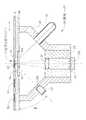
図2は、本分析装置2に組み込まれた測光ヘッド(反射光測定装置)20、及びその周辺部の構成を概略的に示す説明図である。測光ヘッド20は、下カバー5の内部に組み込まれ、トレイ6を挟んでインキュベータ8と対向するように設けられている。この測光ヘッド20は、45°の角度(図中θで示す角度)傾けて設けられた光源としてのLED22と、受光した光を光電変換する受光素子24と、この受光素子24に光を結像させる集束レンズ26と、この集束レンズ26を保持するレンズホルダ28、及びこれらの部材を保持する鏡筒30とから構成されている。 FIG. 2 is an explanatory diagram schematically showing the configuration of the photometric head (reflected light measuring device) 20 incorporated in the analyzer 2 and its peripheral part. The photometric head 20 is incorporated in the
この測光ヘッド20の上には、トレイ6を支持するベース40が設けられている。ベース40の受光素子24と対面する位置(以下、測光位置と称す)には、LED22が照射した光を通過させる開口40aが形成されており、この開口40aには、測光ヘッド20内に塵芥が混入することを防ぐ透明な保護ガラス42が嵌め込まれている。 A
また、ベース40には、スライド開口6aに嵌め込まれたスライド3を支持するためのレール(図示は省略)が、トレイ6の第1位置と第2位置との間の移動に対応するように形成されている。トレイ6が第3位置に位置した際には、このレールがなくなり、前述のようにスライド開口6aからスライド3が落下する。 In addition, a rail (not shown) for supporting the
また、トレイ6には、基準濃度を測定するための白板82と黒板84とが測光ヘッド20側に向けて設けられており、トレイ6が第2位置から第1位置へと向かう間に、この白板82と黒板84の測定が行われる。 Further, the
スライド3は、支持体、試薬層、展開層を積層してなる乾式多層フィルム62と、この乾式多層フィルム62を保持する枠体64とから構成されている。枠体64の上面には、血液や尿などの検体を滴下するための滴下用円孔(図1(B)参照)が設けられており、下面には、呈色反応した乾式多層フィルム62の呈色光学濃度を測定するための測光用円孔が設けられている。この測光用円孔から露呈した乾式多層フィルム62の面が測定面となり、白板82と黒板84も、この測定面と面一になるようにされている(以下、測定面には白板82と黒板84との面も含むものとする)。 The
また、ベース40には、スライド3、及び白板82、黒板84の各測定面が測光位置にあることを検出するためのセンサ(図示は省略)がそれぞれ設けられており、測光ヘッド20は、これらのセンサが検出したことに応じて、LED22を、例えば、200msecだけ発光させる。 The
受光素子24は、例えば、フォトダイオードから構成されており、この受光素子24は、各測定面が測光位置にきてLED22が発光した際に、測定面で反射した法線方向の散乱光を受光して光電変換する。この際、LED22が照射する光は、拡散して測定面のみならず、枠体64やトレイ6などの周囲部にも当たってしまう。そのため、受光素子24の前面には、測定面からの散乱反射光のみを受光させるアパーチャ32が設けられている。また、LED22の前面には、照射光の拡散を抑えるためのアパーチャ30aが形成されている。 The
また、LED22が照射した光の各測定面での正反射光は、鏡筒30の内面に当たる。この正反射光が鏡筒30の内面でさらに反射すると、迷光となって受光素子24に入り込み、測定精度を低下させる。そのため、鏡筒30の正反射光が当たる位置には、表面に黒マット処理が施された吸光板(吸光性部材)34が設けられている。なお、吸光板34は、黒マット処理に限らず、例えば、表面に細かな凹凸を設けたものや、全体を艶消し黒の樹脂素材などで成型したものでもよい。さらに、板ではなく、前述の処理を施したラベルを貼り付けるなど、表面に吸光性を有し、鏡筒30の内面に当たる正反射光のスポット径よりも大きいものであれば、如何なるものでもよい。 Further, the regular reflection light on each measurement surface of the light irradiated by the
図3は、測光ヘッド20を上方から見た平面図である。LED22と吸光板34は一対となって、測光位置にある各測定面を中心とした同心円上に複数(本実施形態では7個)設けられている。また、各LED22は、それぞれ異なる波長を有しており、スライド3の試薬に対応した波長のLED22を発光させることにより、複数種の被検成分を容易に測定することができる。本実施形態では、例えば、大型生化学分析装置のグルコースなど27種類の全測定項目に対応する400nm、505nm、540nm、570nm、600nm、625nm、650nmの波長を有する7種類のLED22が用いられる。但し、LED22の波長は上記に限るものではなく、その数も7個に限るものではない。 FIG. 3 is a plan view of the photometric head 20 as viewed from above. The
図4は、LED22と吸光板34との他の配置例を示すものである。図4に示すように、同心円の片側にLED22とアパーチャ30aを、もう片側に吸光板34を、それぞれの郡をなすように連続的に配置してもよい。このように配置することにより、正反射光を隣り合った吸光板34同士で受けることも可能であり、正反射光の迷光化をさらに抑えることができる。 FIG. 4 shows another arrangement example of the
また、LED22の波長は、温度によって変化するので、例えば、LED22を保持する鏡筒30にペルチェ素子などを設けて、一定の温度に調節することが好ましい。また、このような温度調節手段を新たに設ける代わりに、例えば、調節する温度を37℃として、インキュベータ8のヒータでLED22の温度調節を行うようにしてもよい。 In addition, since the wavelength of the
次に、血液中のグルコースを測定する場合を例に、上記構成による本分析装置2の作用について説明する。 Next, the operation of the analyzer 2 having the above-described configuration will be described taking as an example the case of measuring glucose in blood.
先ず図5に示すように、スライド3を第2位置にあるトレイ6のスライド開口6aにセットする。この際、測定すべき被検成分がグルコースであることを、操作装置10の操作部12を操作して本分析装置2に指示する。次に、スライド開口6aにセットした状態でヘパリン採血した新鮮血を検体として一定量、例えば、10μlをスライド3の上部に形成した滴下用円孔から乾式多層フィルム62に滴下する。 First, as shown in FIG. 5, the
検体を滴下した後、第2位置にあるトレイ6を第1位置に向けて移動させていくと、図6に示すように、白板82が測光位置にくる。測光ヘッド20は、これをベース40に設けられたセンサで検出し、グルコースに対応した505nmの波長を有するLED22を発光させる。このように、各測定面が測光位置にきたタイミング(請求項記載の所定の測定タイミングに相当)にのみLED22を発光させることにより、発光によるLED22の自己発熱を抑えて、温度による波長の変化を防止することができる。 After the sample is dropped, when the
受光素子24は、白板82の測定面で反射した法線方向の散乱光を受光して光電変換し、これを白板82の基準濃度として図示せぬ演算制御部に送る。この際、測定面や保護ガラス42による正反射光を、吸光板34が吸収するので、正反射光が迷光となって受光素子24に入り込むことによる測定精度の低下が防止される。 The
トレイ6がさらに第1位置に移動して黒板84が測光位置にくると、測光ヘッド20は、上記と同様に黒板84の基準濃度を測定してこれを演算制御部に送る。 When the
次に、トレイ6が第1位置(図2参照)まで移動したことをベース40に設けられたセンサが検出すると、インキュベータ8が、37℃で約1分間スライド3をインキュベーションする。スライド3には、グルコースに対応した試薬層が予め形成されており、このインキュベーションによって、検体中のグルコース含有量に応じた光学濃度に呈色反応する。 Next, when the sensor provided in the
測光ヘッド20は、インキュベーションが終了した後にスライド3の呈色光学濃度を測定し、これを演算制御部に送る。なお、インキュベータ8によるインキュベーションのタイミングは上記に限ることなく、予めインキュベーションされたスライド3をスライド開口6aにセットし、白板82、黒板84、及びスライド3の測定を、連続して行うようにしてもよい。 The photometric head 20 measures the color optical density of the
演算制御部は、各測定結果を基に種々の演算を行い、検体中のグルコース含有量を得る。測定が終了したスライド3は、トレイ6を第3位置にすることによりスライド開口6aから落下し、排出口9に排出される。以上、グルコースを例に説明したが、本実施形態の生化学分析装置2では、400nmでアミラーゼ、600nmでクレアチニンなどのようにLED22の波長とスライド3の試薬層との組み合わせによって、約27種類の被検成分の分析を行うことができる。 The calculation control unit performs various calculations based on each measurement result to obtain the glucose content in the sample. The
このように、本実施形態の測光ヘッド20によれば、LED22から照射された光が各測定面によって正反射する位置に吸光板34を設けたので、精度のよい測定を行うことができる。また、LED22を各測定面が測光位置にきたタイミングにのみ発光させるのでLED22の温度上昇が少なく、LED22の波長が変化することによる測定精度の低下を抑えることができる。 As described above, according to the photometric head 20 of the present embodiment, the light-absorbing
なお、上記実施形態では、吸光性部材として吸光板34を用いているが、これに限ることなく、例えば、図7に示すように、一端が閉じられた筒形状をなす光トラップ36を用いるようにしてもよい。この光トラップ36は、内面全体に黒マット処理が施されている。正反射光を面で受ける吸光板34では、この吸光板34上で反射してしまった光を再度捕捉することはできない。対して光トラップ36では、光トラップ36内で反射してしまった光を再度捕捉できる可能性があるので、吸光板34よりも確実に正反射光による測定精度の低下を抑えることができる。 In the above embodiment, the
さらに、鏡筒30に当たる正反射光のスポット径が大きい場合などには、鏡筒30の内側全面に黒マット処理などを施すようにしてもよい。また、上記実施形態では、この鏡筒30の内面を14角錐状に形成しているが、円錐状に形成したものであってもよい。 Further, when the spot diameter of specularly reflected light hitting the
また、上記実施形態では、LED22の照射光が、測定面に対して45°の角度θとなるようにLED22を鏡筒30に取り付けているが、角度θはこれに限るものではない。但し、受光素子24が受光する法線方向の散乱光を考慮すると、この角度θは30〜60°であることが好ましい。 Moreover, in the said embodiment, although LED22 is attached to the lens-
上記実施形態では、反射光測定装置の適用例として、生化学分析装置を示したが、本発明はこれに限ることなく、例えば、単方向照明方式を用いた色彩計や分光測色計などに適用してもよい。 In the above embodiment, a biochemical analyzer has been shown as an example of application of the reflected light measurement device, but the present invention is not limited to this, for example, a colorimeter or a spectrocolorimeter using a unidirectional illumination method. You may apply.
2 生化学分析装置
3 化学分析スライド
8 インキュベータ
20 測光ヘッド(反射光測定装置)
22 LED(光源)
24 受光素子
32 アパーチャ
34 吸光板(吸光性部材)
36 光トラップ
2
22 LED (light source)
24
36 Light trap
Claims (9)
Translated fromJapanese前記光源から照射された光が前記測定面によって正反射する位置に、吸光性部材を設けたことを特徴とする反射光測定装置。In the reflected light measuring device that irradiates the measurement surface with a light source provided at a predetermined angle and measures the scattered reflected light from the measurement surface with a light receiving element provided at a position facing the measurement surface,
An apparatus for measuring reflected light, comprising: a light-absorbing member at a position where light emitted from the light source is regularly reflected by the measurement surface.
Using the reflected light measuring apparatus according to any one of claims 1 to 8, scattered reflected light from a substance to be measured dropped on a chemical analysis slide is measured, and the substance to be measured is based on the measurement result. A biochemical analyzer characterized by performing quantitative analysis.
Priority Applications (2)
| Application Number | Priority Date | Filing Date | Title |
|---|---|---|---|
| JP2004285156AJP2006098227A (en) | 2004-09-29 | 2004-09-29 | Reflected light measuring instrument and biochemical analyzer |
| US11/231,906US20060066850A1 (en) | 2004-09-29 | 2005-09-22 | Light measuring device, biochemical analyzer, biochemical analysis method, and spectrophotometer |
Applications Claiming Priority (1)
| Application Number | Priority Date | Filing Date | Title |
|---|---|---|---|
| JP2004285156AJP2006098227A (en) | 2004-09-29 | 2004-09-29 | Reflected light measuring instrument and biochemical analyzer |
Publications (1)
| Publication Number | Publication Date |
|---|---|
| JP2006098227Atrue JP2006098227A (en) | 2006-04-13 |
Family
ID=36238191
Family Applications (1)
| Application Number | Title | Priority Date | Filing Date |
|---|---|---|---|
| JP2004285156APendingJP2006098227A (en) | 2004-09-29 | 2004-09-29 | Reflected light measuring instrument and biochemical analyzer |
Country Status (1)
| Country | Link |
|---|---|
| JP (1) | JP2006098227A (en) |
Cited By (11)
| Publication number | Priority date | Publication date | Assignee | Title |
|---|---|---|---|---|
| JP2011112558A (en)* | 2009-11-27 | 2011-06-09 | Konica Minolta Sensing Inc | White calibration member and optical characteristic measurement system using the same |
| WO2012128014A1 (en)* | 2011-03-23 | 2012-09-27 | テルモ株式会社 | Component measurement device |
| CN103063639A (en)* | 2012-12-31 | 2013-04-24 | 山东鑫科生物科技股份有限公司 | Microbial growth optical detection sensor |
| JP2013076607A (en)* | 2011-09-30 | 2013-04-25 | Fujifilm Corp | Scattered light detector and scattered light detection method |
| JP2013076608A (en)* | 2011-09-30 | 2013-04-25 | Fujifilm Corp | Scattered light detector and scattered light detection method |
| JP2016075578A (en)* | 2014-10-07 | 2016-05-12 | 株式会社リコー | Sheet material detection system, sheet type determination apparatus, image forming apparatus, image reading apparatus, and image forming system |
| JP2016522880A (en)* | 2013-03-15 | 2016-08-04 | リチャード・ハリー・ターナー | System and method for in vitro detection of particles and soluble chemicals in body fluids |
| WO2017217261A1 (en)* | 2016-06-15 | 2017-12-21 | シャープ株式会社 | Spectrometry device |
| CN107607491A (en)* | 2017-11-06 | 2018-01-19 | 崔宝藏 | Dry chemistry reagent light reflectivity detection means |
| CN110192097A (en)* | 2016-11-18 | 2019-08-30 | 美国西门子医学诊断股份有限公司 | The sequence multi-wavelength of liquid assay object measures |
| CN114460792A (en)* | 2022-01-28 | 2022-05-10 | 杭州利珀科技有限公司 | A dome light source device and method of using the same |
- 2004
- 2004-09-29JPJP2004285156Apatent/JP2006098227A/enactivePending
Cited By (16)
| Publication number | Priority date | Publication date | Assignee | Title |
|---|---|---|---|---|
| JP2011112558A (en)* | 2009-11-27 | 2011-06-09 | Konica Minolta Sensing Inc | White calibration member and optical characteristic measurement system using the same |
| WO2012128014A1 (en)* | 2011-03-23 | 2012-09-27 | テルモ株式会社 | Component measurement device |
| JPWO2012128014A1 (en)* | 2011-03-23 | 2014-07-24 | テルモ株式会社 | Component measuring device |
| JP2013076607A (en)* | 2011-09-30 | 2013-04-25 | Fujifilm Corp | Scattered light detector and scattered light detection method |
| JP2013076608A (en)* | 2011-09-30 | 2013-04-25 | Fujifilm Corp | Scattered light detector and scattered light detection method |
| CN103063639A (en)* | 2012-12-31 | 2013-04-24 | 山东鑫科生物科技股份有限公司 | Microbial growth optical detection sensor |
| US10032270B2 (en) | 2013-03-15 | 2018-07-24 | Richard H. Turner | System and methods for the in vitro detection of particles and soluble chemical entities in body fluids |
| JP2016522880A (en)* | 2013-03-15 | 2016-08-04 | リチャード・ハリー・ターナー | System and method for in vitro detection of particles and soluble chemicals in body fluids |
| JP2016075578A (en)* | 2014-10-07 | 2016-05-12 | 株式会社リコー | Sheet material detection system, sheet type determination apparatus, image forming apparatus, image reading apparatus, and image forming system |
| WO2017217261A1 (en)* | 2016-06-15 | 2017-12-21 | シャープ株式会社 | Spectrometry device |
| CN110192097A (en)* | 2016-11-18 | 2019-08-30 | 美国西门子医学诊断股份有限公司 | The sequence multi-wavelength of liquid assay object measures |
| JP2020504292A (en)* | 2016-11-18 | 2020-02-06 | シーメンス・ヘルスケア・ダイアグノスティックス・インコーポレイテッド | Multiple sequential wavelength measurements in liquid assays |
| JP2022043109A (en)* | 2016-11-18 | 2022-03-15 | シーメンス・ヘルスケア・ダイアグノスティックス・インコーポレイテッド | Multiple sequential wavelength measurement of liquid assay |
| CN107607491A (en)* | 2017-11-06 | 2018-01-19 | 崔宝藏 | Dry chemistry reagent light reflectivity detection means |
| CN114460792A (en)* | 2022-01-28 | 2022-05-10 | 杭州利珀科技有限公司 | A dome light source device and method of using the same |
| CN114460792B (en)* | 2022-01-28 | 2024-11-22 | 杭州利珀科技有限公司 | Dome light source device and use method thereof |
Similar Documents
| Publication | Publication Date | Title |
|---|---|---|
| AU725643B2 (en) | Method and device for measuring reflected optical radiation | |
| US7499154B2 (en) | Readhead for optical inspection apparatus | |
| JP2019035758A (en) | Analytical evaluation apparatus, method, and reagent | |
| US7313257B2 (en) | Handheld optical diagnostic device having image system array | |
| KR102287272B1 (en) | Test Apparatus and Control Method thereof | |
| CN101287980A (en) | System for optically analyzing substances | |
| CN1667418A (en) | Multifunctional portable unit for measurement, analysis and diagnosis | |
| JP2007501415A (en) | Apparatus and method for process monitoring | |
| JP2007322208A (en) | Biochemical analyzer | |
| JP7206570B2 (en) | Analysis equipment | |
| EP2466292B1 (en) | System for performing scattering and absorbance assays | |
| JP2006098227A (en) | Reflected light measuring instrument and biochemical analyzer | |
| JP2015514960A (en) | Sample monitor | |
| US20060066850A1 (en) | Light measuring device, biochemical analyzer, biochemical analysis method, and spectrophotometer | |
| JP7692467B2 (en) | Circuit board with built-in light source | |
| CN108007863A (en) | Test device, test system and control method for test device | |
| KR20200040417A (en) | Fluorescence reader device and process in the form of insertion strip for the quantitative measurements | |
| RU2442973C2 (en) | Immunoturbidimetric flatbed analyzer | |
| WO2014067203A1 (en) | Optical measuring device and optical measuring method | |
| CN207366442U (en) | A kind of Urine Analyzer | |
| TWI780472B (en) | Screening test strip reading system | |
| WO2013161664A1 (en) | Coloration analysis device | |
| US12287321B2 (en) | Optical multianalyte detection | |
| JP2006098229A (en) | Biochemical analyzer | |
| CN212872210U (en) | Dry biochemical analysis system |
Legal Events
| Date | Code | Title | Description |
|---|---|---|---|
| A711 | Notification of change in applicant | Effective date:20061226 Free format text:JAPANESE INTERMEDIATE CODE: A712 |