JP2006096444A - Sheet post-treatment device - Google Patents
Sheet post-treatment deviceDownload PDFInfo
- Publication number
- JP2006096444A JP2006096444AJP2004281771AJP2004281771AJP2006096444AJP 2006096444 AJP2006096444 AJP 2006096444AJP 2004281771 AJP2004281771 AJP 2004281771AJP 2004281771 AJP2004281771 AJP 2004281771AJP 2006096444 AJP2006096444 AJP 2006096444A
- Authority
- JP
- Japan
- Prior art keywords
- sheet
- tray
- processing
- post
- standby tray
- Prior art date
- Legal status (The legal status is an assumption and is not a legal conclusion. Google has not performed a legal analysis and makes no representation as to the accuracy of the status listed.)
- Abandoned
Links
Images


Classifications
- B—PERFORMING OPERATIONS; TRANSPORTING
- B65—CONVEYING; PACKING; STORING; HANDLING THIN OR FILAMENTARY MATERIAL
- B65H—HANDLING THIN OR FILAMENTARY MATERIAL, e.g. SHEETS, WEBS, CABLES
- B65H31/00—Pile receivers
- B65H31/30—Arrangements for removing completed piles
- B65H31/3009—Arrangements for removing completed piles by dropping, e.g. removing the pile support from under the pile
- B65H31/3018—Arrangements for removing completed piles by dropping, e.g. removing the pile support from under the pile from opposite part-support elements, e.g. operated simultaneously
- B—PERFORMING OPERATIONS; TRANSPORTING
- B42—BOOKBINDING; ALBUMS; FILES; SPECIAL PRINTED MATTER
- B42C—BOOKBINDING
- B42C1/00—Collating or gathering sheets combined with processes for permanently attaching together sheets or signatures or for interposing inserts
- B42C1/12—Machines for both collating or gathering and permanently attaching together the sheets or signatures
- B—PERFORMING OPERATIONS; TRANSPORTING
- B65—CONVEYING; PACKING; STORING; HANDLING THIN OR FILAMENTARY MATERIAL
- B65H—HANDLING THIN OR FILAMENTARY MATERIAL, e.g. SHEETS, WEBS, CABLES
- B65H31/00—Pile receivers
- B65H31/32—Auxiliary devices for receiving articles during removal of a completed pile
- B—PERFORMING OPERATIONS; TRANSPORTING
- B65—CONVEYING; PACKING; STORING; HANDLING THIN OR FILAMENTARY MATERIAL
- B65H—HANDLING THIN OR FILAMENTARY MATERIAL, e.g. SHEETS, WEBS, CABLES
- B65H2301/00—Handling processes for sheets or webs
- B65H2301/30—Orientation, displacement, position of the handled material
- B65H2301/36—Positioning; Changing position
- B65H2301/362—Positioning; Changing position of stationary material
- B65H2301/3621—Positioning; Changing position of stationary material perpendicularly to a first direction in which the material is already in registered position
- B65H2301/36212—Positioning; Changing position of stationary material perpendicularly to a first direction in which the material is already in registered position centering, positioning material symmetrically relatively to said first direction
- B—PERFORMING OPERATIONS; TRANSPORTING
- B65—CONVEYING; PACKING; STORING; HANDLING THIN OR FILAMENTARY MATERIAL
- B65H—HANDLING THIN OR FILAMENTARY MATERIAL, e.g. SHEETS, WEBS, CABLES
- B65H2301/00—Handling processes for sheets or webs
- B65H2301/40—Type of handling process
- B65H2301/42—Piling, depiling, handling piles
- B65H2301/422—Handling piles, sets or stacks of articles
- B65H2301/4222—Squaring-up piles
- B—PERFORMING OPERATIONS; TRANSPORTING
- B65—CONVEYING; PACKING; STORING; HANDLING THIN OR FILAMENTARY MATERIAL
- B65H—HANDLING THIN OR FILAMENTARY MATERIAL, e.g. SHEETS, WEBS, CABLES
- B65H2301/00—Handling processes for sheets or webs
- B65H2301/40—Type of handling process
- B65H2301/42—Piling, depiling, handling piles
- B65H2301/422—Handling piles, sets or stacks of articles
- B65H2301/4226—Delivering, advancing piles
- B65H2301/42261—Delivering, advancing piles by dropping
- B65H2301/422615—Delivering, advancing piles by dropping from opposite part-support elements, e.g. operated simultaneously
- B—PERFORMING OPERATIONS; TRANSPORTING
- B65—CONVEYING; PACKING; STORING; HANDLING THIN OR FILAMENTARY MATERIAL
- B65H—HANDLING THIN OR FILAMENTARY MATERIAL, e.g. SHEETS, WEBS, CABLES
- B65H2403/00—Power transmission; Driving means
- B65H2403/40—Toothed gearings
- B65H2403/41—Rack-and-pinion, cogwheel in cog railway
- B65H2403/411—Double rack cooperating with one pinion, e.g. for performing symmetrical displacement relative to pinion
Landscapes
- Engineering & Computer Science (AREA)
- Mechanical Engineering (AREA)
- Pile Receivers (AREA)
Abstract
Description
Translated fromJapanese本発明は、MFPの後段に設けられるフィニッシャー等のシート後処理装置に関する。 The present invention relates to a sheet post-processing apparatus such as a finisher provided at a subsequent stage of an MFP.
MFP(Multi Function Peripheral)でプリントしたシートを複数束ねてステイルプルするフィニシャーが知られている。このフィニシャーでは、MFPから送られたシートを順次処理トレイに搬送し、ステイプラにより綴じて排出トレイに排紙する。 A finisher that bundles a plurality of sheets printed by an MFP (Multi Function Peripheral) and staples them is known. In this finisher, sheets sent from the MFP are sequentially conveyed to a processing tray, bound by a stapler, and discharged to a discharge tray.
フィニシャーでの後処理では、ステイプラによる綴じ処理が存在するので、予め第2トレイに一時的にシート束を収容しておき、その後シート束を第1トレイに落下させてからステイプラにより用紙束を閉じる作業をしている。その際、第1トレイに整合板を設けておき、この整合板で第2トレイの横整合を行うようにしたものが知られている(特許文献1)
しかし、引用文献1のものでは部品点数が多いため、装置を十分に小型化することはできなかった。 However, since the number of parts in the cited document 1 is large, the apparatus cannot be sufficiently downsized.
本発明の目的は、シートの横方向の整合を容易にするシート後処理装置を提供することである。 It is an object of the present invention to provide a sheet post-processing apparatus that facilitates lateral alignment of sheets.
本発明のシート後処理装置は、MFP本体から搬送されたシートを受取り搬送する複数のローラと、搬送路の途中に設けられ、後処理が必要な場合に前記ローラから送られたシートを待機させるシートの搬送方向と直交する横方向に開閉自在な待機トレイであって、シートが積載される積載面の下側の面に整合部材が立設されている待機トレイと、この待機トレイを横方向に開閉する開閉機構と、前記待機トレイから送られるシート及び待機トレイを経由せずに搬送路から送られるシートを後処理する前に受け取る処理トレイと、 前記処理トレイ上のシートの整合を行いシート束を形成する整合機構と、前記処理トレイ上の整合されたシート束を後処理する後処理機構と、後処理されたシート束を前記処理トレイから搬送するシート搬送手段と、搬送されたシート束を積載する排紙トレイと、を具備することを特徴とする。 The sheet post-processing apparatus according to the present invention is provided with a plurality of rollers for receiving and transporting a sheet transported from the MFP main body, and in the middle of the transport path, and waits for the sheet sent from the roller when post-processing is necessary. A standby tray that is openable and closable in a lateral direction perpendicular to the sheet conveyance direction, and a standby tray in which an alignment member is erected on the lower surface of the stacking surface on which the sheets are stacked, and the standby tray in the horizontal direction An opening / closing mechanism that opens and closes, a sheet that is sent from the standby tray, and a processing tray that is received before post-processing a sheet that is sent from the conveyance path without passing through the standby tray, and a sheet that is aligned with the sheet on the processing tray An alignment mechanism for forming a bundle, a post-processing mechanism for post-processing the aligned sheet bundle on the processing tray, and a sheet conveying hand for conveying the post-processed sheet bundle from the processing tray When, characterized by comprising a paper discharge tray for stacking the sheet bundle conveyed, the.
本発明では、後処理が必要な場合にシートを待機させる待機トレイを設けておき、この待機のシート積載面の下側の面に立設された整合部材により、処理トレイに移行したシートの横整合を行うようにしたので、シートの横方向の整合を容易にすることができる。 In the present invention, a standby tray that waits for a sheet when post-processing is required is provided, and the side of the sheet transferred to the processing tray is aligned by an alignment member that is erected on the lower surface of the standby sheet stacking surface. Since the alignment is performed, the alignment of the sheets in the lateral direction can be facilitated.
図を参照して本発明の実施例を説明する。 Embodiments of the present invention will be described with reference to the drawings.
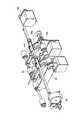
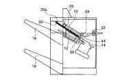
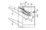
図1は本発明の後処理装置の斜視図、図2は本発明の後処理装置の上面図を表している。この後処理装置は基本的に待機トレイ10、処理トレイ12、ステイプラ14、第1の排紙トレイ16、第2の排紙トレイ18とからなる。 1 is a perspective view of the post-processing apparatus of the present invention, and FIG. 2 is a top view of the post-processing apparatus of the present invention. The post-processing apparatus basically includes a
MFP1(図7参照)から送られてくる用紙20は、一対の入り口ローラ22で受け取られ、一対の給紙ローラ24に供給され、給紙ローラ24から待機トレイ10に送られる。入り口ローラ22は入口ローラモータ26で駆動される。 The
入口ローラ22は、上入口ローラ22a、下入口ローラ22bからなる。給紙ローラも上給紙ローラ、下給紙ローラからなる。 The
待機トレイ10は左右に移動可能な一対の待機トレイ部品10a、10bからならなり、待機トレイ部品10a、10bとの間が狭まった状態で用紙を受け取る。この状態で用紙の整合を行うための待機トレイローラ28が設けられている。待機トレイローラ28は上下に移動可能でその制御は待機トレイローラ駆動源30により実行される。また待機トレイローラ28の回転は待機トレイローラモータ32により行われる。 The
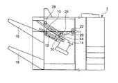
図3に示すように、待機トレイ10に所定の枚数の用紙が蓄積されると、待機トレイモータ34により待機トレイ部品10a、10bが開き、用紙20は自重により処理トレイ12に落下される。この動作をアクティブドロップという。 As shown in FIG. 3, when a predetermined number of sheets are accumulated in the
ここで、待機トレイ10及び処理トレイ12の用紙20の搬送方向の幅は、用紙20の搬送方向の幅より小さい。そして、用紙20が処理トレイ12に落下したときには、用紙20は処理トレイ12と排紙トレイ(図2に示す)に跨って積載される。 Here, the width of the
このように構成することにより、後処理装置の用紙の搬送方向に沿った幅を小さくすることができる。 With this configuration, the width of the post-processing apparatus along the sheet conveyance direction can be reduced.
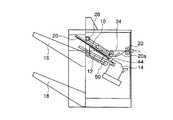
図18を参照して、待機トレイ部品10a,10bの断面及びその開閉機構について説明する。図に示すように、待機トレイ10のシート積載面10cの下側の面には一対の整合部材71a、71bが立設されている。また、待機トレイ10a,10bのシート積載面10cの面の両側には一対に壁部材72a、72bが立設されている。 With reference to FIG. 18, the cross section of the
そして、整合部材71a,71bはラックピニオン機構73の両端に接続されている。そして、ピニオンギア74はステッピングモータ75によりその回転が制御され、このステッピングモータ75の回転はコントローラ76により制御される。 The
MFP1から送られる用紙を待機トレイ10、処理トレイ12に案内するためにペーパーパスが設けられているが、このペーパーパスはペーパーパス天井36により構成される。 A paper path is provided to guide the sheet sent from the MFP 1 to the
処理トレイ12に送られた用紙は、縦整合が実行される。縦整合は、図4に示すように縦整合ローラ38によりなされ、縦整合上ローラ38aは縦整合上ローラモータ40により、縦整合下ローラ38bは縦整合下ローラモータ42により駆動され、用紙をストッパー45を基準に揃える。またこの整合を補助するためにパドル44が設けられ、このパドル44はパドルモータ46により駆動される。 Longitudinal alignment is performed on the sheet sent to the
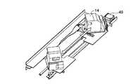
処理トレイ12に所定の枚数の用紙が整合され蓄積されると、ステイプル処理がステイプラ14により行われる。図6に示すように、ステイプラ14はステイプル駆動部49により位置決めされ、ステイプル処理を制御される。 When a predetermined number of sheets are aligned and accumulated in the
ステイプル処理された用紙束は、図4に示すように、搬送機構50により排紙トレイ16に送られる。排紙トレイ16、18の選択は、排紙トレイ駆動部52により排紙トレイ16、18を上下移動させてなされる。 The stapled paper bundle is sent to the
図7乃至18を参照して本発明の後処理装置の動作を説明する。 The operation of the post-processing apparatus of the present invention will be described with reference to FIGS.
図7に示すように、MFP1から送られてきた用紙20は入口ローラ20を介して矢印で示すように給紙ローラ24に送られる。 As shown in FIG. 7, the
次に図8に示すように、給紙ローラ24を通って待機トレイ10に1枚目の用紙が蓄積される。その際待機トレイローラ28が矢印で示すように下がって待機トレイ10に供給された用紙20を待機トレイ10の後端(上流側)60に位置合わせする。 Next, as shown in FIG. 8, the first sheet is accumulated in the
次に図9に示されるように、待機トレイローラ28が上昇し、2枚目の用紙20aを受け入れる準備をする。 Next, as shown in FIG. 9, the
準備が完了すると図10に示されるように2枚目の用紙20aが待機トレイ10に送られ、待機トレイローラ28が下降して用紙の位置を待機トレイ10の後端60に整える。このようにして待機トレイ10には2枚の用紙20、20aからなる用紙束20bが形成される。 When the preparation is completed, as shown in FIG. 10, the
次に図11に示されるように待機トレイローラ28が上昇し、更に図3に示されるように待機トレイ部品10a、10bが開いて、アクティブドロップが図12に示されるように実行され、用紙束20bは処理トレイ12に送られる。 Next, as shown in FIG. 11, the
ここで、図19を参照して待機トレイ10に載置されている用紙束20bが処理トレイ12に落下する過程について詳細に説明する。まず、図19(A)に示すように待機トレイ部品10a、10b上に用紙束20bが載置されている。そして、図19(B)に示すようにコントローラ76によりステッピングモータ75が制御され、待機トレイ部品10a、10bが離間する方向に移動され、用紙束20bが落下を開始する。 Here, a process in which the
用紙束20bが落下すると、図19(C)に示すようにコントローラ76によりステッピングモータ75が制御され、待機トレイ部品10a、10bが近づく方向に移動される。 When the
用紙束20bの落下過程において、待機トレイ部品10a、10bが近づく方向に制御されるので、落下時に図19(C)に示すように用紙束20bの横方向の整合が乱れていても、図19(D)に示すように整合部材71a及び71bにより用紙束20bの横方向の整合をとることができる。 In the process of dropping the
なお、待機トレイ部品10a、10bが近づく方向に制御する際に、ステッピングモータ75を正転、逆転を繰り返すことにより、整合部材71a及び71bを微動させながら近づくようにしても良い。これにより、用紙束20bの用紙の接触面の動摩擦係数を小さくし、横整合を実行しやすくしている。 Note that when the
その後、3枚目からの用紙20cは、図13に示されるように待機トレイ10を経由せずに、給紙ローラ24から直接処理トレイ12に送られ、2枚の用紙束20b上に堆積されて所定枚数の用紙束21を形成する。この際、縦横整合機構38、47が機能して、縦横の用紙整合が実行される。 Thereafter, the
なお、待機トレイ10及び処理トレイ12は、斜めに傾けられて配置されることが望ましい。即ち、それぞれの後端60,62が最も下に位置するようにし、用紙20及び用紙束21の自重によって用紙20及び用紙束21が後端60、62に整合可能にする。 Note that the
次に図14に示すように、用紙束21をステイプラ14によりステイプル処理する。そして、図15に示すように、搬送機構50により用紙束20を排紙トレイ16に送り、後処理が終了する。 Next, as shown in FIG. 14, the
なお、後処理を必要としない場合には、図16、17に示すように処理トレイ12を経由せず待機トレイ10から直接排紙トレイ16に排紙する。図16に示すように、MFP1から送られてきた用紙は入口ローラ22、給紙ローラ24、待機トレイ10を介して、排紙トレイ16に送られる。待機トレイローラ28は下降して用紙20の搬送を行う。排紙トレイ16は図17に示されるように、排紙トレイ駆動部52により若干上昇させられ、待機トレイ10から送られる用紙を受け取る。 When post-processing is not required, the paper is discharged directly from the
なお、処理トレイ12にも図5に示すように、横整合機構47を設けるようにしても良い。 The
さらに、上記実施の形態では待機トレイ部品10a、10bとの間が狭まった状態で用紙を受け取っていたが、閉じた状態で用紙を受け取るようにしても良い。 Further, in the above embodiment, the sheet is received in a state where the space between the
本発明の実施例を一実施形態を参照して説明してきたが、本発明はこの実施例に限定されない。実施例に示された各構成要素はその機能が同じであれば他の構成要素に変更可能である。 Although an example of the present invention has been described with reference to one embodiment, the present invention is not limited to this example. Each component shown in the embodiment can be changed to another component as long as the function is the same.
10・・・待機トレイ、12・・・処理トレイ、14・・・ステイプラ、16・・・第1の排紙トレイ、18・・・第2の排紙トレイ、20・・・用紙、21・・・用紙束、22・・・入り口ローラ、22a・・・上入口ローラ、22b・・・下入口ローラ、24・・・給紙ローラ、26・・・入口ローラモータ、28・・・待機トレイローラ、30・・・待機トレイローラ駆動源、32・・・待機トレイローラモータ、34・・・待機トレイモータ、36・・・ペーパーパス天井、38・・・縦整合ローラ38、40・・・縦整合上ローラモータ、42・・・縦整合下ローラモータ、44・・・パドル、45・・・ストッパー、46・・・パドルモータ、47・・・横整合機構、48・・・横整合モータ、49・・・ステイプル駆動部、50・・・搬送機構、52・・・排紙トレイ駆動部、60・・・待機トレイの後端、62・・・処理トレイの後端、71a,71b・・・整合部材、73…ラックピニオン機構、75…ステッピングモータ、76…コントローラ。DESCRIPTION OF
Claims (3)
Translated fromJapanese搬送路の途中に設けられ、後処理が必要な場合に前記ローラから送られたシートを待機させるシートの搬送方向と直交する横方向に開閉自在な待機トレイであって、シートが積載される積載面の下側の面に整合部材が立設されている待機トレイと、
この待機トレイを横方向に開閉する開閉機構と、
前記待機トレイから送られるシート及び待機トレイを経由せずに搬送路から送られるシートを後処理する前に受け取る処理トレイと、
前記処理トレイ上のシートの整合を行いシート束を形成する整合機構と、
前記処理トレイ上の整合されたシート束を後処理する後処理機構と、
後処理されたシート束を前記処理トレイから搬送するシート搬送手段と、
搬送されたシート束を積載する排紙トレイと、
を具備することを特徴とするシート後処理装置。A plurality of rollers for receiving and conveying a sheet conveyed from the MFP main body;
A standby tray that is provided in the middle of the conveyance path and can be opened and closed in a lateral direction perpendicular to the sheet conveyance direction for waiting for a sheet sent from the roller when post-processing is required. A standby tray in which an alignment member is erected on the lower surface of the surface;
An opening / closing mechanism for horizontally opening and closing the standby tray;
A processing tray for receiving the sheet sent from the standby tray and the sheet sent from the transport path without going through the standby tray before post-processing;
An alignment mechanism for aligning sheets on the processing tray to form a sheet bundle;
A post-processing mechanism for post-processing the aligned sheet bundle on the processing tray;
Sheet conveying means for conveying a post-processed sheet bundle from the processing tray;
A paper discharge tray for stacking conveyed sheet bundles;
A sheet post-processing apparatus comprising:
Priority Applications (5)
| Application Number | Priority Date | Filing Date | Title |
|---|---|---|---|
| JP2004281771AJP2006096444A (en) | 2004-09-28 | 2004-09-28 | Sheet post-treatment device |
| US11/008,567US7300045B2 (en) | 2004-09-28 | 2004-12-10 | Waiting tray for sheet processing tray |
| US11/008,392US7175174B2 (en) | 2004-09-28 | 2004-12-10 | Waiting tray for sheet processing tray |
| US11/822,611US7648136B2 (en) | 2004-09-28 | 2007-07-09 | Sheet post-process apparatus |
| US12/634,439US7802788B2 (en) | 2004-09-28 | 2009-12-09 | Sheet post-process apparatus |
Applications Claiming Priority (1)
| Application Number | Priority Date | Filing Date | Title |
|---|---|---|---|
| JP2004281771AJP2006096444A (en) | 2004-09-28 | 2004-09-28 | Sheet post-treatment device |
Publications (1)
| Publication Number | Publication Date |
|---|---|
| JP2006096444Atrue JP2006096444A (en) | 2006-04-13 |
Family
ID=36098120
Family Applications (1)
| Application Number | Title | Priority Date | Filing Date |
|---|---|---|---|
| JP2004281771AAbandonedJP2006096444A (en) | 2004-09-28 | 2004-09-28 | Sheet post-treatment device |
Country Status (2)
| Country | Link |
|---|---|
| US (1) | US7175174B2 (en) |
| JP (1) | JP2006096444A (en) |
Cited By (6)
| Publication number | Priority date | Publication date | Assignee | Title |
|---|---|---|---|---|
| JP2009107749A (en)* | 2007-10-29 | 2009-05-21 | Fuji Xerox Co Ltd | Post-processing apparatus and image forming apparatus |
| JP2012188194A (en)* | 2011-03-09 | 2012-10-04 | Ricoh Co Ltd | Paper sheet post-processing apparatus, and image forming apparatus |
| JP2013205589A (en)* | 2012-03-28 | 2013-10-07 | Nisca Corp | Sheet post-processing device |
| JP2016117563A (en)* | 2014-12-22 | 2016-06-30 | シャープ株式会社 | Post-processing device and image formation device |
| JP2019085181A (en)* | 2017-11-01 | 2019-06-06 | 京セラドキュメントソリューションズ株式会社 | Sheet stacking apparatus, sheet post-processing apparatus, and image forming apparatus provided with the same |
| JP2020090376A (en)* | 2018-12-07 | 2020-06-11 | キヤノンファインテックニスカ株式会社 | Sheet loading device and image formation system |
Families Citing this family (6)
| Publication number | Priority date | Publication date | Assignee | Title |
|---|---|---|---|---|
| US7306220B2 (en)* | 2005-01-12 | 2007-12-11 | Pitney Bowes Ltd. | Movable sheet guide |
| US7824534B2 (en)* | 2005-01-25 | 2010-11-02 | Nippon Mining & Metals Co., Ltd. | Copper electrolytic solution containing as additive compound having specific skeleton, and electrolytic copper foil manufactured therewith |
| JP2007022745A (en)* | 2005-07-15 | 2007-02-01 | Konica Minolta Business Technologies Inc | Paper aligning device, and paper post-processing device |
| JP2007168966A (en)* | 2005-12-21 | 2007-07-05 | Toshiba Tec Corp | Paper post-processing device |
| JP2010143647A (en)* | 2008-12-16 | 2010-07-01 | Kyocera Mita Corp | Image forming device |
| US11148898B2 (en)* | 2017-12-13 | 2021-10-19 | Hewlett-Packard Development Company, L.P. | Method and system for stacking printed substrates |
Family Cites Families (51)
| Publication number | Priority date | Publication date | Assignee | Title |
|---|---|---|---|---|
| US4473425A (en) | 1982-05-24 | 1984-09-25 | Eastman Kodak Company | Binding apparatus and method |
| US4611741A (en) | 1985-01-24 | 1986-09-16 | Eastman Kodak Company | Booklet finishing apparatus |
| JPS628965A (en) | 1985-07-05 | 1987-01-16 | Canon Inc | Sorting tray device |
| US4794859A (en) | 1987-10-23 | 1989-01-03 | Hewlett-Packard Company | Active paper drop for printers |
| US4898374A (en) | 1988-06-27 | 1990-02-06 | Imagitek, Inc. | Intermittent drive mechanism for copy stacking |
| US5098074A (en)* | 1991-01-25 | 1992-03-24 | Xerox Corporation | Finishing apparatus |
| JP3155557B2 (en) | 1991-04-11 | 2001-04-09 | 株式会社リコー | Paper processing equipment |
| JP2642804B2 (en)* | 1991-07-06 | 1997-08-20 | キヤノン株式会社 | Sheet sorter |
| US5266781A (en)* | 1991-08-15 | 1993-11-30 | Datacard Corporation | Modular card processing system |
| US5285249A (en) | 1992-09-10 | 1994-02-08 | Eastman Kodak Company | Finishing apparatus for stapling sheets stacked first-to-last or last-to-first |
| US5358238A (en)* | 1993-04-27 | 1994-10-25 | Xerox Corporation | Shared user printer output dynamic "mailbox" system |
| US5289251A (en) | 1993-05-19 | 1994-02-22 | Xerox Corporation | Trail edge buckling sheet buffering system |
| US5709376A (en)* | 1995-01-30 | 1998-01-20 | Ricoh Company, Ltd. | Sheet finisher |
| US5676517A (en) | 1995-07-26 | 1997-10-14 | Lotz; Walter E. | Method and apparatus for stacking thin sheets carrying product |
| US5934140A (en) | 1996-06-19 | 1999-08-10 | Xerox Corporation | Paper property sensing system |
| US5628502A (en) | 1996-08-08 | 1997-05-13 | Xerox Corporation | Low force sheet hole punching system in output compiler of reproduction apparatus |
| NL1003847C2 (en) | 1996-08-21 | 1998-02-26 | Boral B V | Device for stacking plate-shaped elements. |
| US6142461A (en) | 1997-03-31 | 2000-11-07 | Nisca Corporation | Sheet processing device |
| US5971384A (en) | 1997-03-31 | 1999-10-26 | Nisca Corporation | Finishing apparatus and image forming apparatus using the same |
| NL1006471C2 (en)* | 1997-07-04 | 1999-01-05 | Oce Tech Bv | Printing device with selective deposition of printed sheets on height-adjustable carriers. |
| US6065747A (en) | 1998-02-27 | 2000-05-23 | Hewlett-Packard Company | Sheet support tray with compensation for curled sheets |
| US6330999B2 (en)* | 1998-05-14 | 2001-12-18 | Graoco (Japan) Ltd | Set binding, stapling and stacking apparatus |
| JP2000072320A (en)* | 1998-09-02 | 2000-03-07 | Konica Corp | Sheet aftertreatment device and image forming device |
| KR100480463B1 (en)* | 1998-09-17 | 2005-09-12 | 주식회사신도리코 | Paper finishing device |
| JP2000159414A (en)* | 1998-11-27 | 2000-06-13 | Canon Inc | Sheet processing apparatus and image forming apparatus having the same |
| US6357753B1 (en) | 1999-03-16 | 2002-03-19 | Nippon Pillar Packing Co., Ltd. | Cartridge-type mechanical seal |
| JP4154088B2 (en) | 1999-08-05 | 2008-09-24 | グラドコ株式会社 | Sheet post-processing device |
| US6092948A (en) | 1999-06-30 | 2000-07-25 | Xerox Corporation | Method and mechanism for supporting and stacking liquid ink printed sheets |
| JP2001089009A (en) | 1999-09-17 | 2001-04-03 | Minolta Co Ltd | Post-processing device |
| US6450934B1 (en)* | 1999-10-05 | 2002-09-17 | Gradco Japan | High speed post processing machine |
| JP3786561B2 (en) | 2000-04-24 | 2006-06-14 | ニスカ株式会社 | Sheet post-processing device |
| JP4763898B2 (en) | 2000-06-20 | 2011-08-31 | キヤノン株式会社 | Sheet processing method, sheet processing apparatus, and image forming apparatus including the same |
| JP3667211B2 (en)* | 2000-08-14 | 2005-07-06 | ニスカ株式会社 | Image forming apparatus |
| US6712349B2 (en)* | 2000-09-19 | 2004-03-30 | Ricoh Company, Ltd. | Sheet folder with turnover and pressing device |
| JP3685994B2 (en)* | 2000-12-18 | 2005-08-24 | シャープ株式会社 | Sheet post-processing device |
| JP3883392B2 (en)* | 2001-03-08 | 2007-02-21 | シャープ株式会社 | Sheet post-processing device |
| JP2002370864A (en)* | 2001-04-11 | 2002-12-24 | Ricoh Co Ltd | Paper handling equipment |
| US6942206B2 (en) | 2001-08-31 | 2005-09-13 | Canon Kabushiki Kaisha | Sheet treating apparatus and image forming apparatus having the same |
| JP3740400B2 (en) | 2001-09-14 | 2006-02-01 | キヤノンファインテック株式会社 | Sheet material processing apparatus and image forming apparatus |
| US6722646B2 (en)* | 2002-02-19 | 2004-04-20 | Canon Kabushiki Kaisha | Sheet treating apparatus and image forming apparatus |
| JP3887251B2 (en)* | 2002-03-14 | 2007-02-28 | ニスカ株式会社 | Sheet post-processing apparatus and image forming apparatus |
| JP2004026320A (en) | 2002-06-21 | 2004-01-29 | Canon Inc | Sheet thickness detecting device, sheet processing device provided with the device, and image forming device |
| JP2004091108A (en)* | 2002-08-30 | 2004-03-25 | Fuji Xerox Co Ltd | Sheet processor |
| US6733007B2 (en) | 2002-09-05 | 2004-05-11 | Canon Kabushiki Kaisha | Sheet material conveying device; image forming apparatus and sheet processing device |
| EP1555570B1 (en)* | 2002-09-20 | 2015-09-09 | Ricoh Company, Ltd. | Binding apparatus, paper processing apparatus and image forming system |
| JP2004195569A (en)* | 2002-12-17 | 2004-07-15 | Fuji Xerox Co Ltd | Paper processing system and cutter unit |
| US6722650B1 (en) | 2003-02-21 | 2004-04-20 | Xerox Corporation | Systems and methods for trail edge paper suppression for high-speed finishing applications |
| JP4298360B2 (en) | 2003-03-07 | 2009-07-15 | キヤノンファインテック株式会社 | Sheet processing apparatus and image forming apparatus provided with the apparatus |
| US6988728B2 (en) | 2003-04-16 | 2006-01-24 | Kyocera Mita Corporation | Sheet sorter and an image forming apparatus |
| US7172185B2 (en)* | 2003-05-23 | 2007-02-06 | Ricoh Company, Ltd. | Sheet punch device, sheet processing device, image forming system, program, and recording medium |
| US6819906B1 (en)* | 2003-08-29 | 2004-11-16 | Xerox Corporation | Printer output sets compiler to stacker system |
- 2004
- 2004-09-28JPJP2004281771Apatent/JP2006096444A/ennot_activeAbandoned
- 2004-12-10USUS11/008,392patent/US7175174B2/ennot_activeExpired - Fee Related
Cited By (8)
| Publication number | Priority date | Publication date | Assignee | Title |
|---|---|---|---|---|
| JP2009107749A (en)* | 2007-10-29 | 2009-05-21 | Fuji Xerox Co Ltd | Post-processing apparatus and image forming apparatus |
| JP2012188194A (en)* | 2011-03-09 | 2012-10-04 | Ricoh Co Ltd | Paper sheet post-processing apparatus, and image forming apparatus |
| JP2013205589A (en)* | 2012-03-28 | 2013-10-07 | Nisca Corp | Sheet post-processing device |
| JP2016117563A (en)* | 2014-12-22 | 2016-06-30 | シャープ株式会社 | Post-processing device and image formation device |
| JP2019085181A (en)* | 2017-11-01 | 2019-06-06 | 京セラドキュメントソリューションズ株式会社 | Sheet stacking apparatus, sheet post-processing apparatus, and image forming apparatus provided with the same |
| JP7035456B2 (en) | 2017-11-01 | 2022-03-15 | 京セラドキュメントソリューションズ株式会社 | Sheet loading device, sheet post-processing device and image forming device equipped with this |
| JP2020090376A (en)* | 2018-12-07 | 2020-06-11 | キヤノンファインテックニスカ株式会社 | Sheet loading device and image formation system |
| JP7219075B2 (en) | 2018-12-07 | 2023-02-07 | キヤノンファインテックニスカ株式会社 | Sheet stacking device and image forming system |
Also Published As
| Publication number | Publication date |
|---|---|
| US20060066032A1 (en) | 2006-03-30 |
| US7175174B2 (en) | 2007-02-13 |
Similar Documents
| Publication | Publication Date | Title |
|---|---|---|
| JP2006096444A (en) | Sheet post-treatment device | |
| JP4291243B2 (en) | Sheet post-processing device | |
| JP4293446B2 (en) | Sheet post-processing device | |
| JP2007168966A (en) | Paper post-processing device | |
| CN100572239C (en) | Paper post-processing device | |
| US7150452B2 (en) | Waiting tray for sheet processing tray | |
| JP4297361B2 (en) | Sheet post-processing device | |
| JP2007168967A (en) | Paper post-processing device | |
| JP2006096466A (en) | Sheet post-processing device | |
| JP4021888B2 (en) | Sheet post-processing device | |
| JP4057575B2 (en) | Sheet post-processing device | |
| JP4471207B2 (en) | Sheet post-processing device | |
| JP4081075B2 (en) | Sheet post-processing device | |
| US20060066026A1 (en) | Sheet post-process apparatus | |
| JP2006096459A (en) | Sheet post-processing device | |
| US7520499B2 (en) | Waiting tray for sheet processing tray | |
| JP2007076862A (en) | Sheet post-processing device | |
| JP4422664B2 (en) | Sheet post-processing device | |
| JP4135722B2 (en) | Sheet post-processing device | |
| JP2006096468A (en) | Sheet post-processing device | |
| JP2005194105A (en) | Sheet post-processing device | |
| JP2006124160A (en) | Sheet post-processing device | |
| JP2006124162A (en) | Sheet post-processing device |
Legal Events
| Date | Code | Title | Description |
|---|---|---|---|
| A621 | Written request for application examination | Free format text:JAPANESE INTERMEDIATE CODE: A621 Effective date:20070601 | |
| A977 | Report on retrieval | Free format text:JAPANESE INTERMEDIATE CODE: A971007 Effective date:20081028 | |
| A131 | Notification of reasons for refusal | Free format text:JAPANESE INTERMEDIATE CODE: A131 Effective date:20081104 | |
| A762 | Written abandonment of application | Free format text:JAPANESE INTERMEDIATE CODE: A762 Effective date:20081225 |