JP2006096030A - Tape cassette - Google Patents
Tape cassetteDownload PDFInfo
- Publication number
- JP2006096030A JP2006096030AJP2005235966AJP2005235966AJP2006096030AJP 2006096030 AJP2006096030 AJP 2006096030AJP 2005235966 AJP2005235966 AJP 2005235966AJP 2005235966 AJP2005235966 AJP 2005235966AJP 2006096030 AJP2006096030 AJP 2006096030A
- Authority
- JP
- Japan
- Prior art keywords
- tape
- printing
- cassette
- label
- guide
- Prior art date
- Legal status (The legal status is an assumption and is not a legal conclusion. Google has not performed a legal analysis and makes no representation as to the accuracy of the status listed.)
- Granted
Links
Images


Landscapes
- Printers Characterized By Their Purpose (AREA)
- Handling Of Continuous Sheets Of Paper (AREA)
- Electronic Switches (AREA)
Abstract
Translated fromJapaneseDescription
Translated fromJapanese本発明は、テーププリンタなどの印字装置に着脱自在に装着されて、その印字装置によって印字が行われる印字用テープを収納するテープカセットに関する。 The present invention relates to a tape cassette that is detachably attached to a printing apparatus such as a tape printer and stores a printing tape on which printing is performed by the printing apparatus.
従来、長尺の基材テープ(剥離テープ)上にその長手方向に沿って所定の間隔をあけて所定形状の複数のラベルが貼着剤によって貼着された印字用テープをインクリボンとともにカセットケース内に収納してなるテープカセットを印字装置に装着し、その印字装置の印字機構によりインクリボンを介して前記ラベルの部分に所定の印字を行なうようにした印字装置及びこれに使用されるテープカセットが提供されている。 Conventionally, a cassette case with an ink ribbon and a printing tape in which a plurality of labels having a predetermined shape are adhered to a long base tape (peeling tape) at predetermined intervals along the longitudinal direction thereof with an adhesive. A printing apparatus in which a tape cassette housed in the apparatus is mounted on a printing apparatus, and a predetermined printing is performed on the label portion via an ink ribbon by a printing mechanism of the printing apparatus, and a tape cassette used therefor Is provided.
特開平11−78128号公報(特許文献1)には、この種の印字装置及びそれに使用するテープカセットに関する技術が開示されている。このテープカセット内に収納される印字用テープは、貼着剤付のテープがそのテープ面内で所定形状のラベルに区画切断されることで剥離テープ上に剥離可能に設けられ、印字用テープの裏面側となる剥離テープの裏面側には、ラベル内に収まるように印字を行うべくセンサによって検知されるセンサ検知用マークと手動の位置合せ操作に用いる手合わせ用マークとが印字用テープの表面側の各ラベルの位置に対応して設けられている。 Japanese Patent Application Laid-Open No. 11-78128 (Patent Document 1) discloses a technique relating to this type of printing apparatus and a tape cassette used therefor. The printing tape stored in the tape cassette is provided on the peeling tape so as to be peelable by dividing the tape with the adhesive into a predetermined shape label within the tape surface. On the back side of the release tape, which is the back side, are a sensor detection mark that is detected by a sensor to print within the label and a manual alignment mark that is used for manual alignment operation. It is provided corresponding to the position of each label.
このテープカセットを使用するラベル印字では、印字装置にテープカセットを装着する際に、印字用テープをカセットケースから繰り出す方向あるいは引き戻す方向に移動操作することにより、印字用テープの裏面側に設けられた手合わせ用マークをカセットケースの所定の部分に位置合せする。この状態でテープカセットを印字装置内に装着すると、印字装置の印字機構に対してラベルの位置がセットされ、印字が開始されると印字装置のセンサによってセンサ検知用マークが検知され、そのマークの検知に基づいて印字用テープの先端部のラベル領域内に印字が行われる。 In label printing using this tape cassette, when the tape cassette is mounted in the printing apparatus, the printing tape is provided on the back side of the printing tape by moving the printing tape in the direction of drawing out from the cassette case or the direction of pulling it back. The alignment mark is aligned with a predetermined portion of the cassette case. When the tape cassette is mounted in the printing apparatus in this state, the label position is set with respect to the printing mechanism of the printing apparatus. When printing is started, the sensor detection mark is detected by the sensor of the printing apparatus, and the mark Based on the detection, printing is performed in the label area at the tip of the printing tape.
ところで、このようなテープカセットでは、印字用テープを繰出し方向あるいは引戻し方向に移動させて位置合せ操作する際に、印字用テープの移動に応じてそのラベルの縁がテープ移動経路の案内部材に引っ掛かり、この引っ掛かりで剥離テープ上のラベルが剥がれてしまうという不都合がある。このテープカセットではカセットケース内のテープの移動経路にガイドローラやガイドボスなどの案内部材が設けられ、印字用テープのラベルを形成した印字面側が案内部材に摺接してテープ移動が行われるが、このテープカセット構造ではラベルの剥がれについて考慮されていないため、特にテープ戻し方向に印字用テープを移動したときに、ラベルの剥がれが生じやすい。 By the way, in such a tape cassette, when the printing tape is moved in the feeding direction or the pulling-back direction and the alignment operation is performed, the edge of the label is caught by the guide member of the tape moving path according to the movement of the printing tape. This has the disadvantage that the label on the release tape is peeled off by this catch. In this tape cassette, guide members such as guide rollers and guide bosses are provided in the tape movement path in the cassette case, and the printing surface side on which the label of the printing tape is formed is in sliding contact with the guide member, and the tape is moved. Since this tape cassette structure does not consider the peeling of the label, the label is likely to be peeled off particularly when the printing tape is moved in the tape return direction.
そこで、この種の印字用テープにおけるラベルの剥がれを防止する技術として、特開2004−58434号公報(特許文献2)に開示されるものがある。この技術は、印字用テープの走行を案内する案内部材に、印字用テープの幅中央部に相当する部分に凹部を形成し、この凹部内に印字用テープのラベルが通過するようにしたものであり、ラベルテープに形成されるラベル領域以外の領域を前記凹部の両側の凸部に当接させて案内し、ラベル領域には凹部を対応させてこれに当接しないようにしたものである。
前記特許文献1に開示されている技術では、案内部材がラベルの剥がれについて考慮されていないため、特にテープ戻し方向に印字用テープを移動したときに、ラベルの剥がれが生じやすい。また、その案内部材としてローラ構造を用いる場合には、部品点数が多くなり、カセット構造が複雑になる。 In the technique disclosed in
一方、前記特許文献2に開示されている技術では、案内部材がラベル領域に接触することなくテープを案内するため、ラベルの剥がれを防止することができるが、次のような問題がある。 On the other hand, in the technique disclosed in
すなわち、前記案内部材は、印字用テープの幅方向の中央部に対応する部分に凹部を備えているため、印字用テープのラベル部分と案内部材の凹部との間に隙間が形成され、印字用テープのラベル部分以外の領域が案内部材の凹部の両側部分(凹部に対しては凸部となる部分)に当接してこれに支持されている。この印字用テープは剥離テープ上に切込みによってラベルが形成されたラベルテープを貼着剤によって剥離可能に貼着して設けているが、この印字用テープの幅方向の中央部と案内部材との間に隙間があるため、案内部材によって直接の支持を受けない印字用テープの幅方向中央部が、湿度の変化などの影響によってラベル印字面側を凸状として案内部材の凹部内に落ち込むように変形して湾曲する虞がある。このように印字用テープ部材がその幅方向に湾曲すると、ラベルのコーナー部分が剥離テープから剥離して浮き上がることになり、この状態で前述の位置合せ操作を行うと、ラベルの剥離テープからの浮き上がり部分がカセットケース内のテープ移動経路に引っ掛かってラベルが剥がれてしまう虞がある。 That is, since the guide member has a recess in a portion corresponding to the central portion in the width direction of the printing tape, a gap is formed between the label portion of the printing tape and the recess of the guide member. A region other than the label portion of the tape is in contact with and supported by both side portions of the concave portion of the guide member (portions that are convex portions with respect to the concave portion). This printing tape is provided by sticking a label tape on which a label is formed by cutting on the peeling tape so that the label tape can be peeled off by a sticking agent. Because there is a gap between them, the widthwise central part of the printing tape that is not directly supported by the guide member falls into the recess of the guide member with the label printing surface side convex due to the influence of changes in humidity, etc. There is a risk of deformation and bending. When the printing tape member is curved in the width direction in this way, the corner portion of the label is peeled off from the peeling tape and lifted. In this state, the label is lifted off from the peeling tape. There is a possibility that the label is peeled off due to the portion being caught by the tape moving path in the cassette case.
また、印字装置に対して印字用テープの位置合せ操作を行う場合に、誤って印字用テープをカセットケース内に戻し過ぎて印字用テープの先端がカセットケース内に入り込んでしまうことがある。そのような場合に、印字用テープを繰出し方向に移動させてその先端をテープ繰出口からカセットケースの外部に再度繰り出すことが必要になるが、印字用テープには巻き癖がついており、その先端が繰出口の内側に一旦入り込んでしまうと、その繰出しが困難になるという問題がある。この点については、前記特許文献1及び2のいずれのテープカセットにおいても考慮されていない。 Further, when the printing tape alignment operation is performed on the printing apparatus, the printing tape may be mistakenly returned to the cassette case and the leading end of the printing tape may enter the cassette case. In such a case, it is necessary to move the printing tape in the feeding direction and feed the tip again from the tape feed outlet to the outside of the cassette case. However, once it enters the inside of the feeding outlet, there is a problem that the feeding becomes difficult. This point is not considered in any of the tape cassettes of
本発明はこのような点に着目してなされたもので、その目的とするところは、印字用テープをその位置合せのために繰出し方向や引戻し方向に移動させても、その表面のラベルの剥がれを的確に防止でき、また印字用テープの先端がカセットケースの内部に入り込んでもその再繰出しを円滑かつ容易に行なうことができるテープカセットを提供することにある。 The present invention has been made paying attention to such points, and the object of the present invention is to remove the label on the surface even if the printing tape is moved in the feeding direction or the pulling direction for alignment. It is an object of the present invention to provide a tape cassette that can prevent the occurrence of the problem accurately and can smoothly and easily re-feed even if the front end of the printing tape enters the inside of the cassette case.
請求項1に係るテープカセットは、カセットケースと、基材テープに表面を印字が行なわれる印字面とした多数のラベルを貼着してなり、前記カセットケース内に収納される印字用テープとを備え、印字装置に着脱可能に装着されるとともに、前記印字用テープは、前記カセットケースから前記印字装置によって印字が行なわれる印字位置に繰出されて前記ラベルに印字が行なわれる一方、前記ラベルを前記印字位置に対応させるべく、前記カセットケースの内部及び外部の両方向に向けて移動が可能なテープカセットであって、前記カセットケース内部の前記印字用テープの移動経路に設けられ、該移動経路に沿って前記カセットケースの内部及び外部の両方に向けて移動する前記印字用テープを案内する案内部材を備え、前記案内部材は、前記印字用テープの先端が前記カセットケースの内部に入り込んだときにその先端を、前記印字用テープの前記カセットケースの外部に向けた移動操作に応じて前記カセットケースの外部に向けて案内するテープ先端案内部と、前記テープ先端案内部の端部に連なって設けられ、前記印字用テープの前記ラベルの貼着面側にテープ幅方向の略全域で当接する案内面を有し、該案内面を前記ラベルの前記基材テープからの剥がれを防止するべく、前記印字用テープの前記カセットケースの内部に向けた移動方向に対応させて曲面形状に形成してなるラベル貼着面案内部とを備えることを特徴としている。 The tape cassette according to
この場合に、請求項2のように、前記案内部材は、前記カセットケース内の前記移動経路の下流側端部に固定して設けてもよく、請求項3のように、前記カセットケース内の前記移動経路の下流側端部に回動自在にして設けると共に、前記テープ先端案内部の端部を、前記供給コアに巻回されたロール状の前記印字用テープの前記ラベルの貼着面側と反対面側の外周面に当接するように付勢するバネを備えて構成してもよい。 In this case, as in
さらに、請求項4のように、前記案内部材は、前記カセットケース内の前記移動経路の下流側端部に回動自在にして設けると共に、前記カセットケースが所定の向きの姿勢にあるときに、その自重によって回動して前記テープ先端案内部の端部が前記供給コアに巻回されたロール状の前記印字用テープの前記ラベルの貼着面側と反対面側の外周面に当接するように構成してもよい。 Further, as in
そして、前記案内部材を前記カセットケース内の前記移動経路の下流側端部に回動自在にして設ける場合には、請求項5のように、前記案内部材の回動中心から前記案内部材の前記テープ案内部の端部までの距離と前記供給コアの半径とを加えた距離を、前記回動中心と前記供給コアの中心間の距離に等しいか、あるいは大きくすることが好ましい。 And when providing the said guide member in the downstream end part of the said movement path | route in the said cassette case so that rotation is possible, the rotation of the said guide member from the rotation center of the said guide member is carried out like
また、請求項6のように、前記案内部材の案内面は、少なくとも0.8mmの半径の曲面部分を有するものとし、請求項7ないし請求項9のように、前記案内部材の案内面の前記印字用テープの移動方向に沿った断面形状は、略半円形状、略円形状、あるいは略山形状とするものである。 Further, as in
また、請求項10に係るテープカセットは、請求項1に係るテープカセットと同様の構成を備え、さらに、印字用テープの移動経路の下流側端部のカセットケースの外壁に、その移動経路に臨んで前記印字用テープの前記ラベルの貼着面側と反対面に対して手指の接触を可能にする操作窓を有し、前記案内部材を、前記印字用テープの移動経路を間にして前記操作窓に向く位置に設けるものである。 The tape cassette according to
請求項1に係るテープカセットによれば、案内部材が印字用テープのラベルの貼着面側にテープ幅方向の略全域で当接し、カセットケースの内部に向けた移動方向に対応させて曲面形状に形成されたラベル貼着面案内部を備えることで、印字用テープのテープ幅方向の略全域でラベルの貼着面側を支持することになって印字用テープが幅方向で湾曲変形することによって生じるラベル縁部の剥がれを防止するとともに、印字用テープのカセットケースの内部に向けた移動方向に対応する曲面形状によって印字用テープのカセットケースの内部への移動時のラベル縁部の引っ掛かりをなくして滑らかなテープ移動とラベルの剥がれを防止できる。したがって、印字用テープのラベルを印字位置に対応させるべく、印字用テープをカセットケースの内部及び外部の両方向である繰出し方向や引戻し方向に移動させても、印字用テープのラベルの剥がれを的確に防止できる。
また印字用テープのカセットケースの外部に向けた移動に応じて印字用テープの先端をカセットケースの外部に向けて案内するテープ先端案内部を備えたことで、印字用テープの先端がカセットケースの内部に入り込んでもその再繰出しを円滑かつ容易に行なうことができる。According to the tape cassette of the first aspect, the guide member is in contact with the sticking surface side of the label of the printing tape in substantially the entire region in the tape width direction, and has a curved surface shape corresponding to the moving direction toward the inside of the cassette case. By providing the label sticking surface guide portion formed on the tape, the printing tape is curved and deformed in the width direction by supporting the sticking surface side of the label in substantially the entire tape width direction of the printing tape. Prevents the label edge from peeling off, and the curved surface shape corresponding to the moving direction of the printing tape toward the inside of the cassette case prevents the label edge from being caught when the printing tape moves into the cassette case. Without this, smooth tape movement and label peeling can be prevented. Therefore, even if the printing tape is moved in both the feeding direction and the pulling direction which are both inside and outside of the cassette case in order to make the printing tape label correspond to the printing position, the peeling of the label on the printing tape can be accurately performed. Can be prevented.
In addition, by providing a tape tip guide for guiding the tip of the printing tape toward the outside of the cassette case in accordance with the movement of the printing tape toward the outside of the cassette case, the tip of the printing tape can be Even if it enters the inside, the re-feeding can be performed smoothly and easily.
この場合に、請求項2に係るテープカセットのように、案内部材をカセットケースの移動経路の下流側端部に固定して設けるようにすれば、案内部材をカセットケースに一体成形により設けることができ、部品点数が増加することがなく構造を簡単にすることができ、テープカセットの組立が容易である。 In this case, as in the tape cassette according to
また、請求項3に係るテープカセットによれば、回動自在にした案内部材をロール状に巻回された印字用テープの外周面にバネの付勢によって当接させるため、カセットケースの内部に入り込んだ印字用テープの先端をカセットケース外に繰出し操作するときに、案内部材によって印字用テープの先端を確実に案内して容易にカセットケースの外部に引き出すことができる。また、案内部材がバネの付勢によって供給コアに巻回された印字用テープの外周面を押えることによって、印字用テープのばらけを防止することができ、印字用テープのばらけによって生じるラベルの剥がれを防止することができる。 Further, according to the tape cassette of the third aspect, the rotatable guide member is brought into contact with the outer peripheral surface of the printing tape wound in a roll shape by the bias of the spring. When the leading end of the entered printing tape is fed out of the cassette case, the leading end of the printing tape can be reliably guided by the guide member and easily pulled out of the cassette case. In addition, the guide member presses the outer peripheral surface of the printing tape wound around the supply core by the urging force of the spring, so that the printing tape can be prevented from being scattered. Can be prevented.
また、請求項4に係るテープカセットによれば、印字用テープの先端がカセットケースの内部に入り込んだときに、カセットケースを所定の向きの姿勢にした状態で繰出し操作を行えば、案内部材はその自重によって回動して端部が供給コアに巻回された印字用テープの外周面に当接するため、案内部材によって印字用テープの先端を確実に案内して容易にカセットケースの外部に引き出すことができる。 According to the tape cassette of the fourth aspect, when the leading end of the printing tape enters the inside of the cassette case, if the feeding operation is performed with the cassette case in a predetermined orientation, the guide member is The end of the printing tape is rotated by its own weight, and the end part comes into contact with the outer peripheral surface of the printing tape wound around the supply core, so that the leading end of the printing tape is reliably guided by the guide member and easily pulled out of the cassette case. be able to.
そして、請求項5に係るテープカセットによれば、回動自在にしてカセットケース内に設ける案内部材の回動中心から印字用テープの外周面に当接する案内部材の端部までの長さを所定の長さの関係に設定しておくことによって、印字用テープが消耗して供給コアに巻回された印字用テープのロール径が小さくなっても、案内部材の端部をロール状の印字用テープの外周面に当接させることができるため、カセットケースの内部に入り込んだ印字用テープの繰り出し操作を行う際に、印字用テープの先端を案内部材によりガイドして確実にカセットケース外に導くことができ、テープカセットの使用初期から印字用テープを消費し切る最後まで印字用テープの繰出しの操作性を良好に維持することができる。 According to the tape cassette of the fifth aspect, the length from the rotation center of the guide member provided in the cassette case so as to be rotatable to the end portion of the guide member contacting the outer peripheral surface of the printing tape is predetermined. If the printing tape is consumed and the roll diameter of the printing tape wound around the supply core is reduced, the end of the guide member can be used for roll printing. Since the tape can be brought into contact with the outer peripheral surface of the tape, when the printing tape that has entered the cassette case is fed out, the leading end of the printing tape is guided by the guide member and reliably guided out of the cassette case. Thus, the operability of feeding the printing tape can be maintained well from the initial use of the tape cassette to the end of consuming the printing tape.
また、案内部材の案内面を、請求項6に係るテープカセットのように、少なくとも0.8mmの半径の曲面とすることによって印字用テープにおけるラベルの剥がれ防止の効果が得られ、また、請求項7乃至9に係るテープカセットのように、案内面のテープ移動方向に沿った断面形状を、略半円形状、略円形状、あるいは略山形状にして案内部材のラベル貼着面案内部を形成することができる。 In addition, the guide surface of the guide member is a curved surface having a radius of at least 0.8 mm as in the tape cassette according to
また、請求項10に係るテープカセットのように、印字用テープの移動経路の下流側端部に操作窓を設けるとともに、案内部材が印字用テープの移動経路を間にして操作窓に向く位置に設けることにより、操作窓から手指を挿入して印字用テープの移動操作を行う際に、案内部材によって手動操作する手指の力をテープ幅の略全域で受けることができ、案内部材が手指の押圧力の受けになるため、この案内部材を受けとして印字用テープの移動操作をスムーズに行うことができる。 Further, as in the tape cassette according to the tenth aspect, the operation window is provided at the downstream end portion of the printing tape moving path, and the guide member is located at the position facing the operation window with the printing tape moving path in between. Thus, when the finger is inserted from the operation window and the printing tape is moved, the finger manually operated by the guide member can be applied over almost the entire width of the tape. Since the pressure is received, the printing tape can be smoothly moved by receiving the guide member.
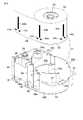
以下、本発明の実施形態を説明する。図1はラベルに印字を行う印字装置の外観斜視図である。また、図2及び図3は図1の印字装置によって印字されるラベルを保持して図1の印字装置に着脱自在に装着される本発明の第1の実施形態に係るテープカセットの外観斜視図及び分解状態の斜視図である。 Embodiments of the present invention will be described below. FIG. 1 is an external perspective view of a printing apparatus for printing on a label. 2 and 3 are external perspective views of the tape cassette according to the first embodiment of the present invention, which holds the label printed by the printing apparatus of FIG. 1 and is detachably attached to the printing apparatus of FIG. FIG.
まず、ラベルに印字を行う印字装置の構成について図1を参照して説明する。図1に示すように、印字装置1は、装置本体2の上面にキー入力部3、表示部4、及び開閉蓋5を備えている。キー入力部3は、印字する文字列のデータを入力する文字キー、印字開始を指示する印字キー、表示部4の表示画面上のカーソルを移動操作するカーソルキー、及び入力された文字列の編集処理、各種設定処理、印字処理等に必要な種々の制御キーを備えている。表示部4は液晶表示装置であり、入力されたデータや処理内容を表示する。
装置本体2は、印字用テープ34及びインクリボン35を収納した図2及び図3に示すテープカセット21を着脱自在に装着するためのカセット装着部6を有し、このカセット装着部6の上面の開口が開閉蓋5により開閉される。開閉蓋5には、カセット装着部6を閉じたときにその内部の視認を可能にする視認窓5aが設けられている。
また、開閉蓋5の裏側には、カセット装着部6に装着されるテープカセット21の位置を規制するためのカセット押え5b、5c、5dが突出して設けられており、開閉蓋5の開放側の端部には装置本体2に設けられた受部2aに係止されて開閉蓋5を閉位置に保持するフック5eが設けられ、装置本体2の上面に設けられた蓋開放ボタン2bの操作でフック5eの係止が解除されて開閉蓋5の開放が可能になっている。First, the configuration of a printing apparatus for printing on a label will be described with reference to FIG. As shown in FIG. 1, the
The apparatus
On the back side of the opening /
カセット装着部6の内部には、テープカセット21に収納された印字用テープ34とインクリボン35とを重ねて所定の方向に搬送するプラテンローラ8、インクリボン35を介して印字用テープ34に印字を行うサーマルヘッド9及び使用済のインクリボン35を巻き取るリボン巻取軸10が設けられている。装置本体2の側方には印字済の印字用テープ34を装置外に排出するためのテープ排出口17が設けられ、このテープ排出口17の近傍にカッタ操作ボタン18aの操作によって作動する印字用テープ34の先端部を切断するテープカッタ18が設けられている。また、プラテンローラ8及びサーマルヘッド9が設けられる位置より下流側の位置には、印字用テープ34に付されたセンサ検知用マーク44bを検知するための光学センサからなるマーク検知センサ13が設けられている。さらに、カセット装着部6の内部には、テープカセット21を位置決めして支持する支持部11が複数箇所に設けられており、テープカセット21の種類を検出するための複数個のマイクロスイッチからなるカセット検知センサ14が設けられている。 Inside the
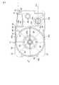
次に、図1の印字装置に使用される本発明の第1の実施形態のテープカセットについて、図2ないし図5を参照して説明する。図2は第1の実施形態に係るテープカセットの全体斜視図、図3は分解斜視図、図4は内部構造を示す平面図、図5は図4中のA―A線断面図である。このテープカセット21は、上ケース22aと下ケース22bを組み合せて構成したカセットケース22を備えており、このカセットケース22の内部は仕切壁22cによってテープ収納部22dとリボン収納部22eとに区画されている。テープ収納部22dにはテープ供給コア23及びそのテープ供給コア23に巻回されて印字用テープ(ラベルテープ)34が収納され、リボン収納部22eにはリボン供給コア24及びそのリボン供給コア24に巻回されてインクリボン35が収納されているとともに、使用済部分のインクリボン35を巻き取るリボン巻取コア25が収納される。 Next, the tape cassette according to the first embodiment of the present invention used in the printing apparatus of FIG. 1 will be described with reference to FIGS. 2 is an overall perspective view of the tape cassette according to the first embodiment, FIG. 3 is an exploded perspective view, FIG. 4 is a plan view showing the internal structure, and FIG. 5 is a cross-sectional view taken along line AA in FIG. The
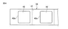
図7、図8及び図9はテープカセットに収納される印字用テープの裏面図、表面図、断面図の各図である。図7ないし図9に示すように、テープ供給コア23に巻回された印字用テープ34は、長尺な剥離テープ(基材テープ)40、及びこの剥離テープ40の表面上に貼着剤45を介して剥離可能に貼着されたラベルテープ41を備え、このラベルテープ41には、切込み線42aを介して所定形状に型取りされて区画されてなるラベル42がラベルテープ41の長手方向に沿って所定の間隔をあけて並ぶように複数設けられている。このラベル42の表面はサーマルヘッド9によって印字が行われる印字面となる。 7, 8 and 9 are a back view, a front view and a cross-sectional view of the printing tape stored in the tape cassette. As shown in FIGS. 7 to 9, the
また、ラベルテープ41の裏面側に貼着された剥離テープ40の裏面には、各ラベル42に対応し各ラベル42の搬送方向の下流側に位置させて、一対の三角形からなる手合わせ用マーク44aとバー形状のセンサ検知用マーク44bが印刷により予め施されている。この手合わせ用マーク44aは、印字用テープ34の最先端側に位置するラベル42から順に無駄なく使用して印字を行なうために、印字装置1にテープカセット21を装着する際に印字装置1の印字位置に対して最先端のラベル42を印字可能な位置に設定するべく、ユーザが手動操作により印字用テープ34の先端部をテープカセット21の所定の基準位置に位置合せするためのものである。また、センサ検知用マーク44bは印字装置1のマーク検知センサ13によって印字用テープ34の位置を検知するためのものであり、このマーク44bの検知に基づいて印字装置1ではラベル42の領域内に印字が収まるように制御を行う。 Further, on the back surface of the peeling
そして、この印字用テープ34は、多数のラベル42が配置されているラベルテープ41側(ラベル貼着面側)を内向きとし手合わせ用マーク44a及びセンサ検知用マーク44bが表示されている剥離テープ40の裏面側を外向きにしてテープ供給コア23に巻回されている。 The
なお、この印字用テープ34は、ラベルテープ41(ラベル42)の裏面側に貼着剤45が塗布されており、剥離テープ(基材テープ)40から剥離したラベル42の裏面側には貼着剤45が付着しているが、逆に基材テープ40上に貼着剤45を塗布しておき、ラベル42の裏面側にはラベル42を基材テープ40から剥離したときに貼着剤45が残らない処理を施しておいてもよい。 The
印字用テープ34を巻回したテープ供給コア23は、カセットケース22の下ケース22bに一体に形成された起立軸23aに印字用テープ34を繰り出す方向とそれとは逆の引き戻す方向とに回転可能にして嵌合されている。これにより、印字用テープ34の手合わせ用マーク44aをテープカセット21の所定の基準位置に位置合せするために、印字用テープ34をカセットケース22から繰り出す方向に移動させたり引き戻す方向に移動させたりすることができる。
また、インクリボン35を巻回したリボン供給コア24は下ケース22bに一体に形成された起立軸24aに回転可能に嵌合され、リボン巻取コア25は上ケース22aと下ケース22bとの間に回転可能に支持されている。The
The
テープ供給コア23に巻回されたロール状の印字用テープ34は、その幅方向の両側の小口面34aがテープコア23の両端から突出する状態にある。そして印字用テープ34の両小口面34aには、両小口面34aから外部に貼着剤45が食み出すことを防止し、ロール状にして重ね巻きした状態の印字用テープ34の巻きが緩んでばらけるのを防止するために、例えばプラスチック材からなるフィルム状のカバー部材39がそれぞれ貼着されている。各カバー部材39は内面に貼着剤を有し、その貼着剤を介して印字用テープ34の小口面34aに貼り付けられている。各カバー部材39は、外径寸法が印字用テープ34の外径寸法よりやや大きい円形の平面ドーナツ状をなし、小口面34aの全域を覆うように貼り付けられている。 The roll-shaped
また、カセットケース22の下ケース22bの内面には、前記起立軸23aを中心として放射状に延びる複数のリブ20が一体に形成され、これらリブ20に前記印字用テープ34の一方の小口面34aに貼り付けられたカバー部材39が滑動自在に接触している。なお、カセットケース22の上ケース22aの内面にも、同様の放射状のリブが形成されている。 Further, a plurality of
カセットケース22には、その外壁の一部を凹状に成形して印字装置1への装着時にサーマルヘッド9が配置されて印字用テープ34に対して印字が行われる印字位置となるヘッド挿入部26が設けられている。このヘッド挿入部26の一側部側(印字用テープ34及びインクリボン35の搬送方向の上流側)には、印字用テープ34及びインクリボン35をカセットケース22の外部に繰出すための繰出口28が形成され、また、ヘッド挿入部26の他側部側(印字用テープ34及びインクリボン35の搬送方向の下流側)には、前記インクリボン35をカセットケース22内に還流させるためのリボン戻し口32が形成されている。そしてヘッド挿入部26より下流側のカセットケース22の側壁の外面が、印字用テープ34を走行させてカセットケースの22の外方に排出させるガイド面30となっている。 A part of the outer wall of the
このガイド面30の所定位置には、ユーザが手動操作により印字用テープ34に施された手合わせ用マーク44aを用いて印字用テープ34上の印字すべきラベル42(最もテープ先端側にあるラベル)を印字装置1の印字位置に対応させるべく位置合せを行う位置合せ部31が設けられている。
この位置合せ部31は、手合わせ用マーク44aを用いた印字用テープ34の先端位置合せの基準位置となるとともに、プラテンローラ8によって搬送されてガイド面30に沿って走行する印字用テープ34のガイド機能も有しており、ガイド面30上に立設して印字用テープ34の幅方向の動きを規制して印字用テープ34の蛇行を防止する側端部ガイド片31aと、ガイド面30と対向して配置しガイド面30からの印字用テープ34の浮き上がりを防止する押え片31bとが一体に設けられている。
なお、図示の側端部ガイド片31aと押え片31bとを有する一対のガイド部材を設けるとともに、手合わせ用マーク44aの位置合せを行う基準位置を別に設けてもよい。その場合に、位置合せ部31は、印字用テープ34の位置合せの機能を有するものであれば、印刷などによるマークなどの標記であってもよく、その形状は任意なものとすることができる。At a predetermined position of the
The
In addition, while providing a pair of guide member which has the side edge
さらに、テープカセット21のカセットケース22の隅部には、カセット装着部6内の支持部11によって支持される複数の支持受部27が形成されている。なお、図示はしていないが支持受部27の1つには、カセット検知センサ14の複数のマイクロスイッチを選択的にオン・オフする所定の形状の識別部が設けられ、印字装置1に対してカセット装着部6に装着されるテープカセットの種類の情報を提供できるように構成されている。この印字装置には、ラベルの形状やサイズの異なる印字用テープを収容した複数種類のテープカセットが用意されており、これらのテープカセットの種類が識別可能になっている。 Further, a plurality of
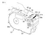
前記カセットケース22の繰出口28の近傍位置、すなわち、カセットケース22内を印字用テープ34が移動する移動経路の下流側端部位置には、印字用テープ34の移動経路上に臨むように案内部材50が下ケース22bに一体に成形されて、カセットケース22内に固定して設けられている。
図6には案内部材50の拡大図を示してある。この案内部材50はプレート状をなし、繰出口28の縁部28aと離間して平行に並び、かつ印字用テープ34の移動経路をカセットケース22内から繰出口28に向けて絞り込むようにして、印字用テープ34の移動経路の下流側端部に斜めに傾斜するように配置されている。The
FIG. 6 shows an enlarged view of the
この案内部材50の幅は印字用テープ34の幅と同じか、それより大きくなっている。この案内部材50の下流側端部を除くプレート面の全域は、印字用テープ34の先端がカセットケース22内に入り込んだときに、ユーザによる繰出し操作によってその先端を繰出口28に向けて移動するように案内するテープ先端案内部51となっており、この案内部材50の下流側端部は、前記テープ先端案内部51に連なる案内面52aからなるラベル貼着面案内部52となっている。
このラベル貼着面案内部52は、繰出口28の縁部28aより若干上方に位置し、繰出口28からカセットケース22外に繰出された印字用テープ34が、印刷動作時に、このラベル貼着面案内部52の案内面52aに印字用テープ34のラベル貼着面がその幅方向の全域で接触し、この状態を保ちながら印字装置1の印字位置を通って装置外に移動するようになっている。
また、印字動作に先立って最初にテープカセット21をカセット装着部6に装着するときに行われる印字用テープ34の先端位置合せのときに、印字用テープ34のラベル貼着面がその幅方向の全域でラベル貼着面案内部52に接触するようになる。そして、ラベル貼着面案内部52の案内面52aの印字用テープ34の移動方向に沿う断面の形状は、図6に示すように、半径Rの略部分円形状であり、半径Rは1.0mmとなっている。The width of the
The label attaching
Further, when the leading end of the
発明者は、案内面52aの曲面の半径Rを、0.5mm、0.7mm、0.8mm、1.0mm及び2.0mmとした各場合について、ラベルの剥がれが生じるか否かの確認試験を行った。その結果によると、案内面52aの曲面の半径Rが0.5mm及び0.7mmの各場合では、ラベルの縁部に剥がれが生じて実用上の問題があることを確認した。これに対して、案内面52aの曲面の半径Rが0.8mm、1.0mm及び2.0mmの各場合では、ラベルの剥がれは認められず実用上の問題がないことを確認できた。
この確認の結果、案内面52aの曲面の半径Rは、少なくとも0.8mm以上が必要であり、1.0mm以上であれば更に好ましい。このような確認試験を踏まえて、ラベル貼着面案内部52の案内面52aを印字用テープ34のテープカセット21への移動操作に対応してラベルの剥がれを防止できる曲面形状及び曲面半径に設定したことにより、印字用テープ34の繰出し時のラベル42の貼着面と案内面52aとの摺動負荷を小さく抑え、かつ印字用テープ34の引戻し時にラベル42が案内面52aに引っ掛かるのをより確実に防止することができる。The inventor confirmed whether or not label peeling occurred in each case where the radius R of the curved surface of the
As a result of this confirmation, the radius R of the curved surface of the
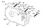
また、ヘッド挿入部26の近傍に位置する印字用テープ34の移動経路の下流側端部には、テープ収納部22aの外周位置にあって印字用テープ34の移動経路に臨むとともに、繰出口28に連なるように第1の操作窓43aがカセットケース22の外壁に開口して形成されている。
この第1の操作窓43aは、前述の印字用テープ34の先端位置合せの作業を行うときに使用されるものであり、この第1の操作窓43aからユーザが指先を挿入して印字用テープ34の裏面側となる剥離テープ40の表面に指先を押し当てて印字用テープ34を繰出し方向や引戻し方向に移動させることができるようになっている。この第1の操作窓43aは、前記案内部材50が設けられている印字用テープ34の移動経路の下流側端部に設けられているため、前記案内部材50は印字用テープ34の移動経路を間にして前記第1の操作窓43aに向く位置に配置されることになる。In addition, the downstream end of the moving path of the
The
また、前記第1の操作窓43aより上流側に位置するカセットケース22の外壁には、手指を挿入してテープコア23に巻回された印字用テープ34の剥離テープ40側に指先を押し当てテープコア23を回転させて印字用テープ34を繰出し方向に移動させるための第2の操作窓43bが設けられている。
この第2の操作窓43bは、印字用テープ34の先端が第1の操作窓43aを超えてカセットケース22内に入り込んでしまった場合に利用するものであり、この窓43bを利用することで印字用テープ34の先端を繰出すことができる。46は第1の操作窓43a内の繰出口28の近傍に設けたテープ押えである。Also, a finger core is pressed against the peeling
The
次に、前記テープカセット21を用いて前記印字装置1によりラベル42への印字を行う場合のユーザの操作手順について説明する。まず、ユーザはテープカセット21を印字装置1のカセット装着部6内に装着するときに、印字用テープ34の先端の位置合せ作業を行う。
図2に図示のように、各ラベル42に対応してその裏面側に設けられている最先端の一対の手合せ用マーク44a、44aの間にテープカセット21の位置合せ部31が位置している状態が適正なテープ先端位置となる。このような状態にしてテープカセット21を印字装置1に装着し印字を開始すると、位置合せ部31に位置合せした一対の手合せ用マーク44a、44aの直ぐ下流側に位置する最先端のラベル42の領域内に収まるように印字が行われるようになっている。
印字用テープ34の先端が図2の状態より下流側に繰出されていれば上流側に戻す必要があり、また、印字用テープ34の先端が図2の状態より上流側に後退していれば下流側に繰出す必要がある。
図10は印字用テープ34の先端が下流側に出過ぎた場合を示しており、その場合には、図11に図示のように、ユーザは前記第1の操作窓43a及び位置合せ部31が上向きとなる姿勢にしてテープカセット21を保持し、その第1の操作窓43a内の印字用テープ34の裏面側に手指を添えて印字用テープ34をカセットケース22内に引き戻すように操作することで、位置合せ部31と手合わせ用マーク44aとで先端位置合せを行う。Next, the operation procedure of the user when printing on the
As shown in FIG. 2, the
If the leading end of the
FIG. 10 shows a case where the leading end of the
このように、テープカセット21をカセット装着部6内に装着する前には、第1の操作窓43aに露出している印字用テープ34に指先を押し当てて印字用テープ34を繰出し方向あるいは引戻し方向に移動させて印字用テープ34の裏面の手合わせ用マーク44aをカセットケース22の位置合せ部31に合せる操作を行なうが、印字用テープ34を引戻し方向に移動させた際には、ラベル42が案内部材50のラベル貼着面案内部52の上を通過する。ラベル貼着面案内部52は曲面形状の案内面52aを備えており、このためラベル42の縁が剥離テープ40から浮き上がっているような場合であっても、そのラベル42はラベル貼着面案内部52に引っ掛かるようなことなくそのラベル貼着面案内部52の上を円滑に通過し、したがってラベル42の剥がれを防止することができる。
また、印字用テープ34はその幅方向の全域がラベル貼着面案内部52の案内面52aに当接しており、このため印字用テープ34を操作するユーザーの指先の圧力が印字用テープ34に加わっても、印字用テープ34は幅方向に湾曲するようなことがなく、ラベル42の剥がれをより確実に防止することができる。As described above, before the
Further, the entire area of the
また、印字用テープ34の先端が、少なくとも第1の操作窓43a内あるときには、第1の操作窓43a内に手指を入れて印字用テープ34を引き出して位置合せすることができるが、印字用テープ34の先端がさらに上流側のカセットケース22内に入り込んでしまった場合には、第2の操作窓43bに手指を挿入してテープ供給コア23をテープ繰出し方向に回転させ、印字用テープ34の先端を第1の操作窓43aに向けて移動させる。第1の操作窓43a内には、案内部材50が設けられているため、テープ供給コア23をテープ繰出し方向に回転させれば、この操作により、図6に示すように、印字用テープ34の先端が案内部材50のテープ先端案内部51に当接する。
このテープ先端案内部51は印字用テープ34の繰出し方向に向かって斜めに傾斜しており、このため印字用テープ34の先端はテープ先端案内部51に沿って移動して繰出口28に達し、その繰出口28から円滑に繰出される。以下、前述の第1の操作窓43aを用いた操作によって位置合せ作業を行えばよい。Further, when the tip of the
The tape leading
このように、印字用テープ34の先端がカセットケース22の内部に入り込んでもその再繰出しを円滑かつ容易に行なうことができ、したがってテープカセット21が使用不能となるようなことがない。 Thus, even if the tip of the
以上の手順により、印字用テープ34の先端の位置合せを行った後、テープカセット21を印字装置1のカセット装着部6に装着する。テープカセット21のカセット装着部6への装着によりサーマルヘッド9がテープカセット21のヘッド挿入部26内に配置されるとともにインクリボン巻取軸10がリボン巻取コア25に嵌入する。このとき、最先端のラベル42に対応するセンサ検知用マーク44bは印字装置1のマーク検知センサ13の上流側に位置している。この状態から、印字開始の指示があると、プラテンローラ8が駆動されて印字用テープ34及びインクリボン35が重ねて搬送され、まずセンサ検知用マーク44bがマーク検知センサ13の位置を通過することで検知され、この検知信号に基づいてサーマルヘッド9が駆動されてラベル42の領域内に印字が行われる。 After the alignment of the leading end of the
ラベル42の印字枚数の設定が1枚であれば、1つのラベル印字が終了した後に所定距離のテープ搬送の後にテープ搬送を停止し、表示部4にカッタ操作を促すメッセージが表示される。ユーザがそのメッセージに従ってカッタ操作ボタン18aの操作によりカッタ18を動作させれば、最先端の1枚のラベル42が切り離される。この状態では、印字用テープ34の先端は図2の状態になっている。
また、印字枚数の設定が複数枚であれば、センサ検知マーク44bを検知する毎に設定複数枚のラベル印字を連続して行い、印字が終了すると、所定距離のテープ搬送の後にテープ搬送を停止し、表示部4にカッタ操作を促すメッセージが表示される。ユーザがそのメッセージに従ってカッタ操作ボタン18aの操作によりカッタ18を動作させれば、先端より複数枚分のラベル42が切り離される。この状態では、印字用テープ34の先端は図2の状態になっている。したがって、一旦印字装置1への装着時に手合せマーク44aを用いた印字用テープ34の先端の位置合せを行えば、テープカセット21を印字装置1外に取り出すなどにより先端の位置が移動することがない限り、先端の位置合せを行うことなく継続して印字を行うことができる。If the number of prints of the
If the number of prints is set to a plurality of sheets, the set number of labels are continuously printed every time the
この印字装置1では、プラテンローラ8が一方向だけに回転駆動され、テープカセット21から繰出された印字用テープ34は下流側に搬送されるのみであるため、最先端のラベル42に対応するセンサ検知マーク44bがマーク検知センサ13の位置より下流側に位置して印字を開始すると、その最先端のセンサ検知マーク44bは認識されず、最先端のラベル42への印字ができなくなり、センサ検知マーク44bが検知可能な先端より2番目以降のラベルに印字が行われるようになって、ラベルが無駄になってしまう。前述の先端位置合せを行うことでそのような不都合を回避することができる。 In this
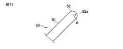
図12には、案内部材50の変形例を示してあり、この場合の案内部材50は印字用テープの先端を案内するテープ先端案内部51と、印字用テープのラベル貼着面を案内するラベル貼着面案内部52とを有し、ラベル貼着面案内部52の印字テープの移動方向に沿う断面の形状が、案内部材50の板厚と略同じ直径の略半円形状となっている。このラベル貼着面案内部52の略半円形状の案内面52aの半径Rは1.0mmとしている。このような案内部材50においても前記実施形態と同様の作用効果を得ることができる。 FIG. 12 shows a modification of the
図13には、案内部材50の他の変形例を示してあり、この場合の案内部材50は印字用テープの先端を案内するテープ先端案内部51と、印字用テープのラベル貼着面を案内するラベル貼着面案内部52とを有し、ラベル貼着面案内部52の印字テープの移動方向に沿う断面の形状が略円形状となっている。このラベル貼着面案内部52の略円形状の案内面52aの半径Rは2.0mmとしている。このような案内部材50においても前記実施形態と同様の作用効果を得ることができる。 FIG. 13 shows another modified example of the
図14には、案内部材50のさらに異なる他の変形例を示してあり、この場合の案内部材50は印字用テープの先端を案内するテープ先端案内部51と、印字用テープのラベル貼着面を案内するラベル貼着面案内部52とを有し、ラベル貼着面案内部52の印字テープの移動方向に沿う断面の形状が略山形状で、その山形頂部が滑らかな曲面の案内面52aとなっている。このラベル貼着面案内部52の案内面52aの半径Rは1.0mmとしている。このような案内部材50においても前記実施形態と同様の作用効果を得ることができる。 FIG. 14 shows still another modified example of the
なお、前記実施形態においては、剥離テープに貼着剤付のラベルテープを貼着し、そのラベルテープに切込み線を施すことにより所定形状のラベルを区画形成してラベルをもつ印字用テープとしたが、予め所定形状に型抜きして形成した複数のラベルを剥離テープの上に所定間隔をあけてそれぞれ貼着剤により貼り付けて印字テープとするような場合であってもよい。 In the above-described embodiment, a label tape with a sticking agent is attached to the release tape, and a label having a predetermined shape is formed by forming a cut line on the label tape to form a printing tape having a label. However, it may be a case where a plurality of labels formed by punching in a predetermined shape in advance are pasted on the release tape with a predetermined interval, respectively, and pasted with an adhesive to form a print tape.
また、前記実施形態においては、印字装置のテープ搬送機構は、印字用テープをテープカセットから繰出す方向にのみ搬送するものであり、ユーザがテープの所定の位置合せ処理を行う目的で印字用テープをカセットケースから繰出す方向又は巻き戻す方向の両方向に手動操作によって移動することについて説明した。
しかし、本発明のテープカセットは、印字用用テープをテープカセットの外部に向けた一方向にのみ搬送するテープ搬送機構を備えた印字装置に限定されず、印字用テープをテープカセットから繰出す方向又は巻き戻す方向の両方に向けて搬送可能なテープ搬送機構を備え、その印字用テープの搬送によって所定の処理を行うようにした印字装置に対しても使用することができる。
すなわち、その場合には、前記実施形態のユーザの手動操作による印字用テープの移動ではなく、モータを駆動源とするテープ搬送機構によってテープ搬送が自動的に行われるものであるが、このような装置によるテープの自動搬送の場合にあっても、本発明のように構成したテープカセットでは、手動操作による場合と同様に、ラベルの剥がれを防止でき、カセットケース内に入り込んだテープの先端部のカセットケース外への再繰出しを容易できるという効果を得ることができる。In the embodiment, the tape transport mechanism of the printing apparatus transports the printing tape only in the direction in which the printing tape is fed out from the tape cassette, and the printing tape is used for the purpose of the user performing a predetermined alignment process of the tape. It has been explained that the sheet is moved by manual operation in both directions of feeding out from the cassette case or rewinding.
However, the tape cassette of the present invention is not limited to a printing apparatus provided with a tape transport mechanism that transports the printing tape only in one direction toward the outside of the tape cassette, and the direction in which the printing tape is fed out from the tape cassette. Alternatively, the present invention can also be used for a printing apparatus that includes a tape transport mechanism capable of transporting in both directions of rewinding and performs predetermined processing by transporting the printing tape.
That is, in that case, the tape is not automatically moved by the user's manual operation of the embodiment, but the tape is automatically conveyed by the tape conveying mechanism using the motor as a drive source. Even in the case of automatic transport of tape by the apparatus, the tape cassette configured as in the present invention can prevent the peeling of the label as in the case of manual operation, and can prevent the leading end of the tape that has entered the cassette case. The effect that re-feeding out of the cassette case can be facilitated can be obtained.
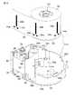
次に、第2の実施形態に係るテープカセットついて図15乃至図21を参照して説明する。なお、第1の実施形態と同一の構成部分については、共通の符号を付してその説明を適宜省略する。図15は、本発明の第2の実施形態に係るテープカセットの分解状態の斜視図、図16及び図17はその要部の構造を示している。
第1の実施形態のテープカセット21では、案内部材50がカセットケース22に固定して設けられているが、この第2の実施形態のテープカセット21aは、案内部材60がカセットケース22に回動自在に設けられると共に、その案内部材60がバネ66によってテープ供給コア23に巻回されたロール状の印字用テープ34に向けて付勢されている点が第1の実施形態と異なるところである。
案内部材60は印字用テープ34の移動経路の下流側端部に配置して設けられ、この案内部材60も、第1の実施形態のテープカセット21の案内部材50と同様にプレート状をなし、繰出口28の縁部28aと離間して平行に並ぶように配置されている。そしてこの案内部材60の幅は印字用テープ34の幅と同じか、それより大きくなっている。
この案内部材60の下流側端部を除くプレート面の全域は、印字用テープ34の先端がカセットケース22内に入り込んだときに、ユーザによる繰出し操作によってその先端を繰出口28に向けて移動するように案内するテープ先端案内部61となっており、この案内部材60の下流側端部は、前記テープ先端案内部61に連なる案内面62aからなるラベル貼着面案内部62となっている。このラベル貼着面案内部62は、繰出口28の縁部28aより若干上方に位置し、繰出口28からカセットケース22外に繰出された印字用テープ34が、印刷動作時に、このラベル貼着面案内部62の案内面62aに印字用テープ34のラベル貼着面がその幅方向の全域で接触し、この状態を保ちながら印字装置1の印字位置を通って装置外に移動するようになっている。
また、印字動作に先立って最初にテープカセット21aを印字装置1のカセット装着部6に装着するときに行われる印字用テープ34の先端位置合せのときに、印字用テープ34のラベル貼着面がその幅方向の全域でラベル貼着面案内部62に接触するようになる。そして、ラベル貼着面案内部62の案内面62aの印字用テープ34の移動方向に沿う断面の形状は、図16に示すように、半径Rの略部分円形状であり、半径Rは1.0mmとなっている。Next, a tape cassette according to a second embodiment will be described with reference to FIGS. In addition, about the component same as 1st Embodiment, a common code | symbol is attached | subjected and the description is abbreviate | omitted suitably. FIG. 15 is an exploded perspective view of the tape cassette according to the second embodiment of the present invention, and FIGS. 16 and 17 show the structure of the main part thereof.
In the
The
The entire area of the plate surface excluding the downstream end of the
In addition, when the leading end of the
この第2の実施形態においても、発明者は、案内面62aの曲面の半径Rを、0.5mm、0.7mm、0.8mm、1.0mm及び2.0mmとした各場合について、ラベルの剥がれが生じるか否かの確認試験を行った。その結果によると、案内面62aの曲面の半径Rが0.5mm及び0.7mmの各場合では、ラベルの縁部に剥がれが生じて実用上の問題があることを確認した。これに対して、案内面62aの曲面の半径Rが0.8mm、1.0mm及び2.0mmの各場合では、ラベルの剥がれは認められず実用上の問題がないことを確認できた。
この確認の結果、案内面62aの曲面の半径Rは、少なくとも0.8mm以上が必要であり、1.0mm以上であれば更に好ましい。このような確認試験を踏まえて、ラベル貼着面案内部62の案内面62aを印字用テープ34のテープカセット21aへの移動操作に対応してラベルの剥がれを防止できる曲面形状及び曲面半径に設定したことにより、印字用テープ34の繰出し時のラベル42の貼着面と案内面62aとの摺動負荷を小さく抑え、かつ印字用テープ34の引戻し時にラベル42が案内面62aに引っ掛かるのをより確実に防止することができる。Also in the second embodiment, the inventor makes the label in each case where the radius R of the curved surface of the
As a result of this confirmation, the radius R of the curved surface of the
ラベル貼着面案内部62の両側には支軸65が設けられており、この支軸65がカセットケース22の上ケース22a及び下ケース22bに形成された不図示の軸受けによって軸支されている。この支軸65部分には両端部が案内部材60とカセットケース22側とに設けられた係止部67、68に係止されてバネ66が設けられ、このバネ66によって案内部材60がテープ供給コア23に向けて弾性的に付勢されて案内部材60のラベル貼着面案内部62とは反対側の上流側端部がテープ供給コア23に巻回された印字用テープ34の裏面に当接するようになっている。この場合、図18のように、案内部材60の回動中心から案内部材60の上流側端部までの距離Lとテープ供給コア23の半径Aとを加えた距離が、案内部材60の回動中心とテープ供給コア23の中心間の距離Dに等しいか、あるいはそれより大きい関係(D≦R+L)になっている。
図19は第2の実施形態のテープカセット21aの使用初期状態を示し、図20は使用途中の状態を示している。図示のように、印字による印字用テープ34の消費に応じて徐々にロール径が小さくなっていくが、第1の実施形態のテープカセット21では、ロール径が小さくなると案内部材50の上流側端部とロール状態の印字用テープ34との間に隙間が生じ、それが徐々に拡大することになる。
前述のように、印字用テープ34の先端がカセットケース22内に入り込んでしまった場合には、前記第2の操作窓44bを用いて繰り出し操作を行うことになる。本来であれば、印字用テープ34の先端が案内部材50に案内されてカセットケース22外に再繰り出しされることになるが、前記隙間があるために、先端を含めてロール状の印字用テープ34がカセットケース22内で回転するだけで、印字用テープ34の先端がうまく案内部材50に引っ掛からないことがある。印字用テープ34の消費が進んで前記隙間が大きくなったときにその傾向が大きくなる。FIG. 19 shows an initial use state of the
As described above, when the leading end of the
これに対し、この第2の実施形態のテープカセット21aでは、案内部材60がバネ66によって付勢されてその上流側端部がテープ供給コア23に巻回された印字用テープ34の外周面に弾性的に当接することにより前記隙間は生じない。このため、印字用テープ34の先端がカセットケース22内に入り込んでしまったとしても、繰り出し操作によってロール状態の印字用テープ34を繰り出し方向に回転させると、印字用テープ34の先端が案内部材60に当接し、その先端を確実にカセットケース22外に導くことができる。 On the other hand, in the
また、テープカセット21、21aでは、ロール状の印字用テープ34の小口面に貼着剤付の前記カバー部材39を設けることにより、印字用テープ34のばらけを防止している。この印字用テープ34のばらけが生じると、テープ供給コア23上に重ね巻きした印字用テープ34の巻き付けが緩んでロール状の外周部分の印字用テープ34の巻径がカセットケース22内で拡大し、それによって印字用テープ34の先端がカセットケース22内に引き戻されて入り込んでしまう等の不都合な点がある。
前述のように、ばらけ防止のためのカバー部材39を備えているが、カバー部材39の貼着剤が経時変化によって貼着力が弱まったり、テープカセット取扱時の落下などの衝撃によって貼着が外れたり、あるいは印字用テープ34の先端位置合せのために印字用テープ34を繰り出し方向や引き戻し方向に移動操作するうちにカセットケース22を出たり入ったりする印字用テープ34部分がカバー部材39から剥がれてしまうなど、必ずしもばらけ防止のカバー部材39が機能しないこともある。
第2の実施形態のテープカセット21aでは、案内部材60がバネ66によって常に付勢されてその上流側端部がテープ供給コア23に巻回された印字用テープ34の外周面に当接することにより、カバー部材39の貼着力が弱まって印字用テープ34を重ね巻き状態に保持する力が弱まった場合にも、印字用テープ34が案内部材60に押圧されることによって重ね巻き状態に保持され、ばらけが防止される。
また、ばらけが生じると、テープ供給コア23に巻回された印字用テープ34の巻径が拡大することになるが、この巻径の拡大時に切込みによって印字用テープ34に形成されているラベル42部分が追従することができず、印字用テープ34とその上のラベル42部分に曲率の差が生じて切り込み部分でラベル42が剥離テープ40から剥がれる現象が生じることがある。
この第2の実施形態のテープカセット21aによれば、案内部材60をバネ66によって常に付勢してその上流側端部をテープ供給コア23に巻回された印字用テープ34の外周面に当接させることにより印字用テープ34のばらけの発生を抑止しているため、そのばらけに起因するラベル42の剥離テープ40から剥離現象を防止することができる。Further, in the
As described above, the
In the
Further, when the dispersion occurs, the winding diameter of the
According to the
次に、第3の実施形態に係るテープカセットついて図21及び図22を参照して説明する。なお、第1及び第2の実施形態と同一の構成部分については、共通の符号を付してその説明を適宜省略する。
図21は第3の実施形態のテープカセット21bの使用初期の状態を示し、図20は使用途中の状態を示している。この第3の実施形態に係るテープカセット21bも、第2の実施形態のテープカセット21aと同様に、案内部材70がカセットケース22に支軸75を介して回動自在に取り付けられているが、第2の実施形態のテープカセット21aでは案内部材60をバネ66で付勢しているのに対し、この第3の実施形態ではバネを備えず案内部材70が自重で回動する点が相違する。
前述の図10に図示のように、印字用テープ34の先端の位置合せを行うために、テープカセット21bがその第1の操作窓43a及び位置合せ部31を上向きにした姿勢になるように置かれると、案内部材70がそれ自身の自重によって支軸75を中心に回動して上流側端部がテープ供給コア23に巻回された印字用テープ34の外周に当接するものである。これにより、案内部材70の上流側端部とテープ供給コア23に巻回された印字用テープ34の外周面との間に隙間が生じないため、印字用テープ34の先端がカセットケース22内に入り込んでしまったとしても、第2の実施形態と同様に繰り出し操作によって印字用テープ34の先端を案内部材70によって確実にカセットケース22外に導くことができる。
この案内部材70は、テープカセット21aを前記所定の姿勢に保持したときに、自重による回動が確実に行われるように、上流側端部の厚みを大きくするなどして上流側端部の重量を大きくし重量バランスを上流側端部に片寄らせておくことが望ましい。なお、この第3の実施形態の案内部材70においても、図18に示す第2の実施形態の案内部材60の場合と同様な寸法関係とすることが好ましい。Next, a tape cassette according to a third embodiment will be described with reference to FIGS. In addition, about the same component as 1st and 2nd embodiment, a common code | symbol is attached | subjected and the description is abbreviate | omitted suitably.
FIG. 21 shows an initial use state of the
As shown in FIG. 10 described above, in order to align the front end of the
The
図23ないし図25には第2及び第3実施形態における案内部材60,70の変形例を示してある。図23に示す変形例の案内部材60,70においては、印字用テープの先端を案内するテープ先端案内部61,71と、印字用テープのラベル貼着面を案内するラベル貼着面案内部62,72とを有し、ラベル貼着面案内部62,72の印字テープの移動方向に沿う断面の形状が、案内部材60,70の板厚と略同じ直径の略半円形状となっている。このラベル貼着面案内部62,72の略半円形状の案内面62a,72aの半径Rは1.0mmとしている。このような案内部材60,70においても前記実施形態と同様の作用効果を得ることができる。 23 to 25 show modified examples of the
図24に示す変形例の案内部材60,70においては、印字用テープの先端を案内するテープ先端案内部61,71と、印字用テープのラベル貼着面を案内するラベル貼着面案内部62,72とを有し、ラベル貼着面案内部62,72の印字テープの移動方向に沿う断面の形状が略円形状となっている。このラベル貼着面案内部62,72の略円形状の案内面62a,72aの半径Rは2.0mmとしている。このような案内部材60,70においても前記実施形態と同様の作用効果を得ることができる。 In the
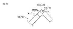
図25に示す変形例の案内部材60,70においては、印字用テープの先端を案内するテープ先端案内部61,71と、印字用テープのラベル貼着面を案内するラベル貼着面案内部62,72とを有し、ラベル貼着面案内部62,72の印字テープの移動方向に沿う断面の形状が略山形状で、その山形頂部が滑らかな曲面の案内面62a,72aとなっている。このラベル貼着面案内部62,72の案内面62a,72aの半径Rは1.0mmとしている。このような案内部材60,70においても前記実施形態と同様の作用効果を得ることができる。 In the
1…印字装置
2…装置本体
3…キー入力部
4…表示部
5…開閉蓋
6…カセット装着部
8…プラテンローラ
9…サーマルヘッド
13…マーク検知センサ
14…カセット検知センサ
17…テープ排出口
21.21a.21b…テープカセット
22…カセットケース
23…テープ供給コア
24…リボン供給コア
25…リボン巻取コア
28…繰出口
30…ガイド面
31…位置合せ部
34…印字用テープ
35…インクリボン
40…基材テープ
41…ラベルテープ
42a…切込み線
42…ラベル
43a…第1の操作窓
43b…第2の操作窓
44b…センサ検知用マーク
44a…手合わせ用マーク
50.60.70…案内部材
51.61.71…テープ先端案内部
52.62.72…ラベル貼着面案内部
52a.62a.72a…案内面
65.75…支軸
66…バネDESCRIPTION OF
Claims (10)
Translated fromJapanese基材テープに表面を印字が行なわれる印字面とした多数のラベルを貼着してなり、供給コアに巻回されて前記カセットケース内に収納される印字用テープとを備え、
印字装置に着脱自在に装着されるとともに、前記印字用テープは、前記カセットケースから前記印字装置によって印字が行なわれる印字位置に繰出されて前記ラベルに印字が行なわれる一方、前記ラベルを前記印字位置に対応させるべく、前記カセットケースの内部及び外部の両方向に向けて移動が可能なテープカセットであって、
前記カセットケース内部の前記印字用テープの移動経路に設けられ、該移動経路に沿って前記カセットケースの内部及び外部の両方に向けて移動する前記印字用テープを案内する案内部材を備え、
前記案内部材は、前記印字用テープの先端が前記カセットケースの内部に入り込んだときに、その先端を、前記印字用テープの前記カセットケースの外部に向けた移動操作に応じて前記カセットケースの外部に向けて案内するテープ先端案内部と、
前記テープ先端案内部の端部に連なって設けられ、前記印字用テープの前記ラベルの貼着面側にテープ幅方向の略全域で当接する案内面を有し、該案内面を前記ラベルの前記基材テープからの剥がれを防止するべく、前記印字用テープの前記カセットケースの内部に向けた移動方向に対応させて曲面形状に形成してなるラベル貼着面案内部とを備えることを特徴とするテープカセット。Cassette case,
A plurality of labels having a printing surface on which a surface is printed on a base tape, and a printing tape wound around a supply core and housed in the cassette case,
The printing tape is detachably attached to the printing apparatus, and the printing tape is fed from the cassette case to a printing position where printing is performed by the printing apparatus, and printing is performed on the label, while the label is printed on the printing position. In order to correspond to the tape cassette is capable of moving in both the inside and the outside of the cassette case,
A guide member that is provided in a movement path of the printing tape inside the cassette case, and that guides the printing tape that moves toward both the inside and the outside of the cassette case along the movement path;
When the leading end of the printing tape enters the inside of the cassette case, the guide member moves the leading end of the printing tape toward the outside of the cassette case according to the moving operation. A tape tip guide that guides toward
A guide surface that is provided continuously to an end portion of the tape leading-end guide portion and abuts on the label attachment surface side of the printing tape in substantially the entire region in the tape width direction; In order to prevent peeling from the base tape, a label sticking surface guide portion formed in a curved shape corresponding to the moving direction of the printing tape toward the inside of the cassette case is provided. Tape cassette to be used.
前記案内部材が、前記移動経路を間にして前記操作窓に向く位置に設けられていることを特徴とする請求項1乃至9のいずれかに記載のテープカセット。On the outer wall of the cassette case at the downstream end of the moving path, an operation window that allows the finger to come into contact with the surface opposite to the label attaching surface side of the printing tape facing the moving path. Have
The tape cassette according to any one of claims 1 to 9, wherein the guide member is provided at a position facing the operation window with the moving path in between.
Priority Applications (1)
| Application Number | Priority Date | Filing Date | Title |
|---|---|---|---|
| JP2005235966AJP4648128B2 (en) | 2004-09-02 | 2005-08-16 | Tape cassette |
Applications Claiming Priority (2)
| Application Number | Priority Date | Filing Date | Title |
|---|---|---|---|
| JP2004255793 | 2004-09-02 | ||
| JP2005235966AJP4648128B2 (en) | 2004-09-02 | 2005-08-16 | Tape cassette |
Publications (3)
| Publication Number | Publication Date |
|---|---|
| JP2006096030Atrue JP2006096030A (en) | 2006-04-13 |
| JP2006096030A5 JP2006096030A5 (en) | 2008-07-31 |
| JP4648128B2 JP4648128B2 (en) | 2011-03-09 |
Family
ID=36236297
Family Applications (1)
| Application Number | Title | Priority Date | Filing Date |
|---|---|---|---|
| JP2005235966AExpired - Fee RelatedJP4648128B2 (en) | 2004-09-02 | 2005-08-16 | Tape cassette |
Country Status (1)
| Country | Link |
|---|---|
| JP (1) | JP4648128B2 (en) |
Cited By (18)
| Publication number | Priority date | Publication date | Assignee | Title |
|---|---|---|---|---|
| JP2010234772A (en)* | 2009-03-31 | 2010-10-21 | Brother Ind Ltd | Tape cassette and tape printer |
| JP2011011399A (en)* | 2009-06-30 | 2011-01-20 | Brother Industries Ltd | Tape cassette |
| JP2011206916A (en)* | 2010-03-26 | 2011-10-20 | Brother Industries Ltd | Tape cassette |
| US8651756B2 (en) | 2008-12-25 | 2014-02-18 | Brother Kogyo Kabushiki Kaisha | Tape cassette |
| US8740482B2 (en) | 2009-03-31 | 2014-06-03 | Brother Kogyo Kabushiki Kaisha | Tape printer |
| US8757907B2 (en) | 2009-03-31 | 2014-06-24 | Brother Kogyo Kabushiki Kaisha | Tape cassette |
| US8764326B2 (en) | 2009-03-31 | 2014-07-01 | Brother Kogyo Kabushiki Kaisha | Tape cassette |
| US8770877B2 (en) | 2008-12-25 | 2014-07-08 | Brother Kogyo Kabushiki Kaisha | Tape printer |
| US9132682B2 (en) | 2009-03-31 | 2015-09-15 | Brother Kogyo Kabushiki Kaisha | Tape unit and tape cassette |
| US9174476B2 (en) | 2010-02-26 | 2015-11-03 | Brother Kogyo Kabushiki Kaisha | Ribbon guide in a tape cassette |
| US9352600B2 (en) | 2009-12-16 | 2016-05-31 | Brother Kogyo Kabushiki Kaisha | Tape cassette |
| US9566808B2 (en) | 2009-03-31 | 2017-02-14 | Brother Kogyo Kabushiki Kaisha | Tape cassette |
| US9573401B2 (en) | 2009-06-30 | 2017-02-21 | Brother Kogyo Kabushiki Kaisha | Tape cassette |
| US9656495B2 (en) | 2009-12-28 | 2017-05-23 | Brother Kogyo Kabushiki Kaisha | Tape cassette |
| JP2017226226A (en)* | 2017-09-21 | 2017-12-28 | ブラザー工業株式会社 | Tape cassette |
| JP2019142063A (en)* | 2018-02-19 | 2019-08-29 | カシオ計算機株式会社 | Medium adaptor |
| JP2021006484A (en)* | 2019-06-28 | 2021-01-21 | ブラザー工業株式会社 | cassette |
| US12296580B2 (en) | 2009-03-31 | 2025-05-13 | Brother Kogyo Kabushiki Kaisha | Tape cassette |
Families Citing this family (4)
| Publication number | Priority date | Publication date | Assignee | Title |
|---|---|---|---|---|
| JP5233969B2 (en)* | 2009-11-27 | 2013-07-10 | ブラザー工業株式会社 | Tape cassette and tape printer |
| ATE544604T1 (en) | 2009-06-10 | 2012-02-15 | Brother Ind Ltd | PRINTER |
| EP2371558B1 (en) | 2010-03-31 | 2015-04-15 | Brother Kogyo Kabushiki Kaisha | Thermal printer |
| US8384750B2 (en) | 2010-03-31 | 2013-02-26 | Brother Kogyo Kabushiki Kaisha | Printing apparatus |
Citations (1)
| Publication number | Priority date | Publication date | Assignee | Title |
|---|---|---|---|---|
| JP2004058434A (en)* | 2002-07-29 | 2004-02-26 | Brother Ind Ltd | Label tape cartridge for tape printer |
- 2005
- 2005-08-16JPJP2005235966Apatent/JP4648128B2/ennot_activeExpired - Fee Related
Patent Citations (1)
| Publication number | Priority date | Publication date | Assignee | Title |
|---|---|---|---|---|
| JP2004058434A (en)* | 2002-07-29 | 2004-02-26 | Brother Ind Ltd | Label tape cartridge for tape printer |
Cited By (76)
| Publication number | Priority date | Publication date | Assignee | Title |
|---|---|---|---|---|
| US9656496B2 (en) | 2008-12-25 | 2017-05-23 | Brother Kogyo Kabushiki Kaisha | Tape cassette |
| US10744798B2 (en) | 2008-12-25 | 2020-08-18 | Brother Kogyo Kabushiki Kaisha | Tape cassette |
| US12304229B2 (en) | 2008-12-25 | 2025-05-20 | Brother Kogyo Kabushiki Kaisha | Tape cassette |
| US8651756B2 (en) | 2008-12-25 | 2014-02-18 | Brother Kogyo Kabushiki Kaisha | Tape cassette |
| US12233641B2 (en) | 2008-12-25 | 2025-02-25 | Brother Kogyo Kabushiki Kaisha | Tape cassette |
| US11479053B2 (en) | 2008-12-25 | 2022-10-25 | Brother Kogyo Kabushiki Kaisha | Tape cassette |
| US11285749B2 (en) | 2008-12-25 | 2022-03-29 | Brother Kogyo Kabushiki Kaisha | Tape cassette |
| US10661589B2 (en) | 2008-12-25 | 2020-05-26 | Brother Kogyo Kabushiki Kaisha | Tape cassette |
| US8770877B2 (en) | 2008-12-25 | 2014-07-08 | Brother Kogyo Kabushiki Kaisha | Tape printer |
| US9656497B2 (en) | 2008-12-25 | 2017-05-23 | Brother Kogyo Kabushiki Kaisha | Tape cassette |
| US10189284B2 (en) | 2008-12-25 | 2019-01-29 | Brother Kogyo Kabushiki Kaisha | Tape cassette |
| US9855779B2 (en) | 2008-12-25 | 2018-01-02 | Brother Kogyo Kabushiki Kaisha | Tape cassette |
| US9751349B2 (en) | 2008-12-25 | 2017-09-05 | Brother Kogyo Kabushiki Kaisha | Tape cassette |
| US9682584B2 (en) | 2008-12-25 | 2017-06-20 | Brother Kogyo Kabushiki Kaisha | Tape cassette |
| US9649861B2 (en) | 2008-12-25 | 2017-05-16 | Brother Kogyo Kabushiki Kaisha | Tape cassette |
| US9566812B2 (en) | 2008-12-25 | 2017-02-14 | Brother Kogyo Kabushiki Kaisha | Tape cassette |
| US9539838B2 (en) | 2008-12-25 | 2017-01-10 | Brother Kogyo Kabushiki Kaisha | Tape Cassette |
| US9533522B2 (en) | 2008-12-25 | 2017-01-03 | Brother Kogyo Kabushiki Kaisha | Tape cassette |
| US9522556B2 (en) | 2008-12-25 | 2016-12-20 | Brother Kogyo Kabushiki Kaisha | Tape cassette |
| US9493016B2 (en) | 2008-12-25 | 2016-11-15 | Brother Kogyo Kabushiki Kaisha | Tape cassette |
| US9498997B2 (en) | 2008-12-25 | 2016-11-22 | Brother Kogyo Kabushiki Kaisha | Tape cassette |
| US9498998B2 (en) | 2008-12-25 | 2016-11-22 | Brother Kogyo Kabushiki Kaisha | Tape cassette |
| US9511610B2 (en) | 2008-12-25 | 2016-12-06 | Brother Kogyo Kabushiki Kaisha | Tape cassette |
| US9511611B2 (en) | 2008-12-25 | 2016-12-06 | Brother Kogyo Kabushiki Kaisha | Tape cassette |
| US9511609B2 (en) | 2008-12-25 | 2016-12-06 | Brother Kogyo Kabushiki Kaisha | Tape cassette |
| US8757907B2 (en) | 2009-03-31 | 2014-06-24 | Brother Kogyo Kabushiki Kaisha | Tape cassette |
| US9427988B2 (en) | 2009-03-31 | 2016-08-30 | Brother Kogyo Kabushiki Kaisha | Tape cassette |
| US9409425B2 (en) | 2009-03-31 | 2016-08-09 | Brother Kogyo Kabushiki Kaisha | Tape cassette |
| US9403389B2 (en) | 2009-03-31 | 2016-08-02 | Brother Kogyo Kabushiki Kaisha | Tape cassette |
| US12296580B2 (en) | 2009-03-31 | 2025-05-13 | Brother Kogyo Kabushiki Kaisha | Tape cassette |
| US9381756B2 (en) | 2009-03-31 | 2016-07-05 | Brother Kogyo Kabushiki Kaisha | Tape cassette |
| US9566808B2 (en) | 2009-03-31 | 2017-02-14 | Brother Kogyo Kabushiki Kaisha | Tape cassette |
| US11254149B2 (en) | 2009-03-31 | 2022-02-22 | Brother Kogyo Kabushiki Kaisha | Tape cassette |
| US9592692B2 (en) | 2009-03-31 | 2017-03-14 | Brother Kogyo Kabushiki Kaisha | Tape cassette |
| US9616690B2 (en) | 2009-03-31 | 2017-04-11 | Brother Kogyo Kabushiki Kaisha | Tape cassette |
| US9370949B2 (en) | 2009-03-31 | 2016-06-21 | Brother Kogyo Kabushiki Kaisha | Tape cassette |
| US10201988B2 (en) | 2009-03-31 | 2019-02-12 | Brother Kogyo Kabushiki Kaisha | Tape cassette |
| US10201993B2 (en) | 2009-03-31 | 2019-02-12 | Brother Kogyo Kabushiki Kaisha | Tape cassette |
| US12257827B2 (en) | 2009-03-31 | 2025-03-25 | Brother Kogyo Kabushiki Kaisha | Tape cassette |
| JP2010234772A (en)* | 2009-03-31 | 2010-10-21 | Brother Ind Ltd | Tape cassette and tape printer |
| US11052685B2 (en) | 2009-03-31 | 2021-07-06 | Brother Kogyo Kabushiki Kaisha | Tape cassette |
| US9656488B2 (en) | 2009-03-31 | 2017-05-23 | Brother Kogyo Kabushiki Kaisha | Tape cassette |
| US8740482B2 (en) | 2009-03-31 | 2014-06-03 | Brother Kogyo Kabushiki Kaisha | Tape printer |
| US10618325B2 (en) | 2009-03-31 | 2020-04-14 | Brother Kogyo Kabushiki Kaisha | Tape cassette |
| US8764325B2 (en) | 2009-03-31 | 2014-07-01 | Brother Kogyo Kabushiki Kaisha | Tape cassette |
| US11945217B2 (en) | 2009-03-31 | 2024-04-02 | Brother Kogyo Kabushiki Kaisha | Tape cassette |
| US9132682B2 (en) | 2009-03-31 | 2015-09-15 | Brother Kogyo Kabushiki Kaisha | Tape unit and tape cassette |
| US9011028B2 (en) | 2009-03-31 | 2015-04-21 | Brother Kogyo Kabushiki Kaisha | Tape cassette |
| US9498988B2 (en) | 2009-03-31 | 2016-11-22 | Brother Kogyo Kabushiki Kaisha | Tape cassette |
| US11707938B2 (en) | 2009-03-31 | 2023-07-25 | Brother Kogyo Kabushiki Kaisha | Tape cassette |
| US9346296B2 (en) | 2009-03-31 | 2016-05-24 | Brother Kogyo Kabushiki Kaisha | Tape cassette |
| US10226949B2 (en) | 2009-03-31 | 2019-03-12 | Brother Kogyo Kabushiki Kaisha | Tape cassette |
| US10744802B2 (en) | 2009-03-31 | 2020-08-18 | Brother Kogyo Kabushiki Kaisha | Tape cassette |
| US10675894B2 (en) | 2009-03-31 | 2020-06-09 | Brother Kogyo Kabushiki Kaisha | Tape cassette |
| US8764326B2 (en) | 2009-03-31 | 2014-07-01 | Brother Kogyo Kabushiki Kaisha | Tape cassette |
| US9802432B2 (en) | 2009-06-30 | 2017-10-31 | Brother Kogyo Kabushiki Kaisha | Tape cassette |
| JP2011011399A (en)* | 2009-06-30 | 2011-01-20 | Brother Industries Ltd | Tape cassette |
| US11225099B2 (en) | 2009-06-30 | 2022-01-18 | Brother Kogyo Kabushiki Kaisha | Tape cassette |
| US12194765B2 (en) | 2009-06-30 | 2025-01-14 | Brother Kogyo Kabushiki Kaisha | Tape cassette |
| US9676217B2 (en) | 2009-06-30 | 2017-06-13 | Brother Kogyo Kabushiki Kaisha | Tape cassette |
| US9573401B2 (en) | 2009-06-30 | 2017-02-21 | Brother Kogyo Kabushiki Kaisha | Tape cassette |
| US10265976B2 (en) | 2009-12-16 | 2019-04-23 | Brother Kogyo Kabushiki Kaisha | Tape cassette |
| US9352600B2 (en) | 2009-12-16 | 2016-05-31 | Brother Kogyo Kabushiki Kaisha | Tape cassette |
| US11235600B2 (en) | 2009-12-16 | 2022-02-01 | Brother Kogyo Kabushiki Kaisha | Tape cassette |
| US9539837B2 (en) | 2009-12-16 | 2017-01-10 | Brother Kogyo Kabushiki Kaisha | Tape cassette |
| US11135862B2 (en) | 2009-12-28 | 2021-10-05 | Brother Kogyo Kabushiki Kaisha | Tape cassette with indicator portion having pressing and non-pressing portion for indentifying tape type |
| US9656495B2 (en) | 2009-12-28 | 2017-05-23 | Brother Kogyo Kabushiki Kaisha | Tape cassette |
| US10265982B2 (en) | 2009-12-28 | 2019-04-23 | Brother Kogyo Kabushiki Kaisha | Tape cassette |
| US12128697B2 (en) | 2009-12-28 | 2024-10-29 | Brother Kogyo Kabushiki Kaisha | Tape cassette |
| US9174476B2 (en) | 2010-02-26 | 2015-11-03 | Brother Kogyo Kabushiki Kaisha | Ribbon guide in a tape cassette |
| JP2011206916A (en)* | 2010-03-26 | 2011-10-20 | Brother Industries Ltd | Tape cassette |
| JP2017226226A (en)* | 2017-09-21 | 2017-12-28 | ブラザー工業株式会社 | Tape cassette |
| JP7056211B2 (en) | 2018-02-19 | 2022-04-19 | カシオ計算機株式会社 | Media adapter |
| JP2019142063A (en)* | 2018-02-19 | 2019-08-29 | カシオ計算機株式会社 | Medium adaptor |
| JP7338267B2 (en) | 2019-06-28 | 2023-09-05 | ブラザー工業株式会社 | cassette |
| JP2021006484A (en)* | 2019-06-28 | 2021-01-21 | ブラザー工業株式会社 | cassette |
Also Published As
| Publication number | Publication date |
|---|---|
| JP4648128B2 (en) | 2011-03-09 |
Similar Documents
| Publication | Publication Date | Title |
|---|---|---|
| JP4648128B2 (en) | Tape cassette | |
| EP1288006B1 (en) | Tape cassette | |
| EP2338687B1 (en) | Tape cassette | |
| CN106457850A (en) | printer | |
| TWI641499B (en) | With 匣 | |
| JP2000229750A (en) | Paper cassette and recording paper | |
| US11135863B2 (en) | Cassette provided with guide for correcting curling behavior of tape | |
| JP2000225746A (en) | Printing device and recording paper | |
| JP2005288858A (en) | Tape cassette | |
| JP4449796B2 (en) | Cutting device | |
| CN114670559A (en) | Tape box | |
| JP4457935B2 (en) | Cutting device | |
| US11084304B2 (en) | Cassette including guide for restraining disengagement of tape | |
| JP2006213010A (en) | Tape cassette | |
| HK1070864B (en) | Tape cassette | |
| HK1068116B (en) | Tape cassette | |
| HK1099733B (en) | Tape cassette | |
| JP2006272504A (en) | Sheet material cutting device, sheet material and sheet cassette | |
| HK1068115B (en) | Tape cassette | |
| JP2006248135A (en) | Printing device | |
| JP2009073134A (en) | Printer | |
| HK1068118B (en) | Tape cassette | |
| HK1100541B (en) | Tape cassette | |
| HK1068117B (en) | Tape cassette |
Legal Events
| Date | Code | Title | Description |
|---|---|---|---|
| A521 | Written amendment | Free format text:JAPANESE INTERMEDIATE CODE: A523 Effective date:20080616 | |
| A621 | Written request for application examination | Free format text:JAPANESE INTERMEDIATE CODE: A621 Effective date:20080616 | |
| A131 | Notification of reasons for refusal | Free format text:JAPANESE INTERMEDIATE CODE: A131 Effective date:20100713 | |
| A521 | Written amendment | Free format text:JAPANESE INTERMEDIATE CODE: A523 Effective date:20100816 | |
| TRDD | Decision of grant or rejection written | ||
| A01 | Written decision to grant a patent or to grant a registration (utility model) | Free format text:JAPANESE INTERMEDIATE CODE: A01 Effective date:20101207 | |
| A01 | Written decision to grant a patent or to grant a registration (utility model) | Free format text:JAPANESE INTERMEDIATE CODE: A01 | |
| A61 | First payment of annual fees (during grant procedure) | Free format text:JAPANESE INTERMEDIATE CODE: A61 Effective date:20101209 | |
| FPAY | Renewal fee payment (event date is renewal date of database) | Free format text:PAYMENT UNTIL: 20131217 Year of fee payment:3 | |
| R150 | Certificate of patent or registration of utility model | Ref document number:4648128 Country of ref document:JP Free format text:JAPANESE INTERMEDIATE CODE: R150 Free format text:JAPANESE INTERMEDIATE CODE: R150 | |
| R250 | Receipt of annual fees | Free format text:JAPANESE INTERMEDIATE CODE: R250 | |
| R250 | Receipt of annual fees | Free format text:JAPANESE INTERMEDIATE CODE: R250 | |
| R250 | Receipt of annual fees | Free format text:JAPANESE INTERMEDIATE CODE: R250 | |
| R250 | Receipt of annual fees | Free format text:JAPANESE INTERMEDIATE CODE: R250 | |
| R250 | Receipt of annual fees | Free format text:JAPANESE INTERMEDIATE CODE: R250 | |
| R250 | Receipt of annual fees | Free format text:JAPANESE INTERMEDIATE CODE: R250 | |
| R250 | Receipt of annual fees | Free format text:JAPANESE INTERMEDIATE CODE: R250 | |
| LAPS | Cancellation because of no payment of annual fees |