JP2006095314A - Biopsy device with sample storage - Google Patents
Biopsy device with sample storageDownload PDFInfo
- Publication number
- JP2006095314A JP2006095314AJP2005282466AJP2005282466AJP2006095314AJP 2006095314 AJP2006095314 AJP 2006095314AJP 2005282466 AJP2005282466 AJP 2005282466AJP 2005282466 AJP2005282466 AJP 2005282466AJP 2006095314 AJP2006095314 AJP 2006095314A
- Authority
- JP
- Japan
- Prior art keywords
- tissue
- sample
- cutter
- biopsy device
- bore
- Prior art date
- Legal status (The legal status is an assumption and is not a legal conclusion. Google has not performed a legal analysis and makes no representation as to the accuracy of the status listed.)
- Pending
Links
- 238000001574biopsyMethods0.000titleclaimsabstractdescription104
- 238000003860storageMethods0.000titleclaimsdescription52
- 238000005520cutting processMethods0.000claimsabstractdescription67
- 239000012530fluidSubstances0.000claimsabstractdescription53
- 238000000034methodMethods0.000claimsdescription38
- 238000004891communicationMethods0.000claimsdescription12
- 210000001519tissueAnatomy0.000description365
- 239000000523sampleSubstances0.000description283
- 230000007246mechanismEffects0.000description27
- 230000008021depositionEffects0.000description24
- 238000002595magnetic resonance imagingMethods0.000description17
- 150000003839saltsChemical class0.000description16
- XLYOFNOQVPJJNP-UHFFFAOYSA-NwaterSubstancesOXLYOFNOQVPJJNP-UHFFFAOYSA-N0.000description16
- 239000000463materialSubstances0.000description15
- 238000003384imaging methodMethods0.000description13
- 230000013011matingEffects0.000description11
- 238000005070samplingMethods0.000description9
- 238000009607mammographyMethods0.000description8
- 230000005540biological transmissionEffects0.000description7
- 230000008878couplingEffects0.000description6
- 238000010168coupling processMethods0.000description6
- 238000005859coupling reactionMethods0.000description6
- 239000007788liquidSubstances0.000description6
- 239000000853adhesiveSubstances0.000description5
- 230000001070adhesive effectEffects0.000description5
- 239000002184metalSubstances0.000description5
- 229910052751metalInorganic materials0.000description5
- 230000009467reductionEffects0.000description5
- 238000011282treatmentMethods0.000description5
- FAPWRFPIFSIZLT-UHFFFAOYSA-MSodium chlorideChemical compound[Na+].[Cl-]FAPWRFPIFSIZLT-UHFFFAOYSA-M0.000description4
- 239000012267brineSubstances0.000description4
- 238000002347injectionMethods0.000description4
- 239000007924injectionSubstances0.000description4
- 230000003993interactionEffects0.000description4
- 229920003023plasticPolymers0.000description4
- 239000011780sodium chlorideSubstances0.000description4
- HPALAKNZSZLMCH-UHFFFAOYSA-Msodium;chloride;hydrateChemical compoundO.[Na+].[Cl-]HPALAKNZSZLMCH-UHFFFAOYSA-M0.000description4
- 238000012546transferMethods0.000description4
- 238000005304joiningMethods0.000description3
- 239000004033plasticSubstances0.000description3
- 229920000642polymerPolymers0.000description3
- 239000004800polyvinyl chlorideSubstances0.000description3
- 229920000915polyvinyl chloridePolymers0.000description3
- 238000011084recoveryMethods0.000description3
- 238000002604ultrasonographyMethods0.000description3
- 238000012285ultrasound imagingMethods0.000description3
- 229920000106Liquid crystal polymerPolymers0.000description2
- 239000004977Liquid-crystal polymers (LCPs)Substances0.000description2
- 230000008901benefitEffects0.000description2
- 210000000481breastAnatomy0.000description2
- 239000000919ceramicSubstances0.000description2
- 230000000295complement effectEffects0.000description2
- 238000012790confirmationMethods0.000description2
- 230000009977dual effectEffects0.000description2
- 229920006351engineering plasticPolymers0.000description2
- 238000004519manufacturing processMethods0.000description2
- -1polyethylenePolymers0.000description2
- 230000003252repetitive effectEffects0.000description2
- 210000004872soft tissueAnatomy0.000description2
- 238000013519translationMethods0.000description2
- 239000012780transparent materialSubstances0.000description2
- 238000003466weldingMethods0.000description2
- 239000004698PolyethyleneSubstances0.000description1
- XUIMIQQOPSSXEZ-UHFFFAOYSA-NSiliconChemical compound[Si]XUIMIQQOPSSXEZ-UHFFFAOYSA-N0.000description1
- 229920006362Teflon®Polymers0.000description1
- 238000004026adhesive bondingMethods0.000description1
- 230000004323axial lengthEffects0.000description1
- 230000006835compressionEffects0.000description1
- 238000007906compressionMethods0.000description1
- 230000000881depressing effectEffects0.000description1
- 238000003745diagnosisMethods0.000description1
- 238000010586diagramMethods0.000description1
- 230000008030eliminationEffects0.000description1
- 238000003379elimination reactionMethods0.000description1
- 238000001125extrusionMethods0.000description1
- 230000005294ferromagnetic effectEffects0.000description1
- 239000003302ferromagnetic materialSubstances0.000description1
- 238000010304firingMethods0.000description1
- 229920002313fluoropolymerPolymers0.000description1
- 239000004811fluoropolymerSubstances0.000description1
- 230000000977initiatory effectEffects0.000description1
- 238000003780insertionMethods0.000description1
- 230000037431insertionEffects0.000description1
- 239000002198insoluble materialSubstances0.000description1
- 230000004807localizationEffects0.000description1
- 238000003754machiningMethods0.000description1
- 239000007769metal materialSubstances0.000description1
- 150000002739metalsChemical class0.000description1
- 238000000465mouldingMethods0.000description1
- 239000004417polycarbonateSubstances0.000description1
- 229920000515polycarbonatePolymers0.000description1
- 229920000573polyethylenePolymers0.000description1
- 238000002360preparation methodMethods0.000description1
- 230000008569processEffects0.000description1
- 239000011347resinSubstances0.000description1
- 229920005989resinPolymers0.000description1
- 230000002441reversible effectEffects0.000description1
- 230000011218segmentationEffects0.000description1
- 229910052710siliconInorganic materials0.000description1
- 239000010703siliconSubstances0.000description1
- 239000007787solidSubstances0.000description1
- 125000006850spacer groupChemical group0.000description1
- 239000000126substanceSubstances0.000description1
- 238000006467substitution reactionMethods0.000description1
- 238000001356surgical procedureMethods0.000description1
- 238000012360testing methodMethods0.000description1
- 238000011179visual inspectionMethods0.000description1
- 238000012800visualizationMethods0.000description1
Images


Classifications
- A—HUMAN NECESSITIES
- A61—MEDICAL OR VETERINARY SCIENCE; HYGIENE
- A61B—DIAGNOSIS; SURGERY; IDENTIFICATION
- A61B10/00—Instruments for taking body samples for diagnostic purposes; Other methods or instruments for diagnosis, e.g. for vaccination diagnosis, sex determination or ovulation-period determination; Throat striking implements
- A61B10/02—Instruments for taking cell samples or for biopsy
- A61B10/0233—Pointed or sharp biopsy instruments
- A61B10/0266—Pointed or sharp biopsy instruments means for severing sample
- A61B10/0275—Pointed or sharp biopsy instruments means for severing sample with sample notch, e.g. on the side of inner stylet
- A—HUMAN NECESSITIES
- A61—MEDICAL OR VETERINARY SCIENCE; HYGIENE
- A61B—DIAGNOSIS; SURGERY; IDENTIFICATION
- A61B10/00—Instruments for taking body samples for diagnostic purposes; Other methods or instruments for diagnosis, e.g. for vaccination diagnosis, sex determination or ovulation-period determination; Throat striking implements
- A61B10/02—Instruments for taking cell samples or for biopsy
- A61B10/0233—Pointed or sharp biopsy instruments
- A61B10/0283—Pointed or sharp biopsy instruments with vacuum aspiration, e.g. caused by retractable plunger or by connected syringe
- A—HUMAN NECESSITIES
- A61—MEDICAL OR VETERINARY SCIENCE; HYGIENE
- A61B—DIAGNOSIS; SURGERY; IDENTIFICATION
- A61B10/00—Instruments for taking body samples for diagnostic purposes; Other methods or instruments for diagnosis, e.g. for vaccination diagnosis, sex determination or ovulation-period determination; Throat striking implements
- A61B10/02—Instruments for taking cell samples or for biopsy
- A61B2010/0225—Instruments for taking cell samples or for biopsy for taking multiple samples
Landscapes
- Health & Medical Sciences (AREA)
- Life Sciences & Earth Sciences (AREA)
- Surgery (AREA)
- Animal Behavior & Ethology (AREA)
- Biomedical Technology (AREA)
- Heart & Thoracic Surgery (AREA)
- Medical Informatics (AREA)
- Molecular Biology (AREA)
- Pathology (AREA)
- Engineering & Computer Science (AREA)
- General Health & Medical Sciences (AREA)
- Public Health (AREA)
- Veterinary Medicine (AREA)
- Surgical Instruments (AREA)
- Sampling And Sample Adjustment (AREA)
- Investigating Or Analysing Biological Materials (AREA)
Abstract
Description
Translated fromJapanese〔関連出願に対するクロス・リファレンス〕
本特許出願は、以下の共通に譲渡されている特許出願、すなわち、トンプソン(Thompson)他の名義で2004年2月24日に出願されている「バイオプシー・デバイス・ウィズ・バリアブル・スピード・カッター・アドバンス(Biopsy Device with Variable Speed Cutter Advance)」を発明の名称とする米国特許出願第10/785,755号、ヒブナー(Hibner)他の名義で2003年9月30日に出願されている「バイオプシー・インストルメント・ウィズ・インターナル・スペシミン・コレクション・メカニズム(Biopsy Instrument with Internal Specimen Collection Mechanism)」を発明の名称とする米国特許出願第10/676,944号、およびシセナス(Cicenas)他の名義で2003年12月10日に出願されている「バイオプシー・デバイス・ウィズ・サンプル・チューブ(Biopsy Device with Sample Tube)」を発明の名称とする米国特許出願第10/732,843号を、クロス・リファレンスし、参照して含んでいる。[Cross Reference for Related Applications]
This patent application includes the following commonly assigned patent applications: “Biopsy Device With Variable Speed Cutter”, filed February 24, 2004 in the name of Thompson et al. US patent application Ser. No. 10 / 785,755, entitled “Biopsy Device with Variable Speed Cutter Advance”; “Biopsy Device” filed on September 30, 2003 in the name of Hibner et al. US patent application Ser. No. 10 / 676,944 entitled “Biopsy Instrument with Internal Specimen Collection Mechanism” and 2003 under the name of Cicenas et al. "Biopsy device with sample," filed on December 10, US patent application Ser. No. 10 / 732,843, whose title is “Biopsy Device with Sample Tube”, is cross-referenced and incorporated by reference.
〔発明の分野〕
本発明は一般に生検装置に関連しており、特に、組織を切断するためのカッターを有する生検装置に関連している。(Field of the Invention)
The present invention generally relates to a biopsy device, and more particularly to a biopsy device having a cutter for cutting tissue.
〔発明の背景〕
組織の診断および治療がこの研究の継続中の領域である。後のサンプリングおよび/または試験のために組織サンプルを得るための種々の医療装置が当業界において知られている。例えば、商品名をマンモトーム(MAMMOTOME)として現在販売されている生検器具が、胸(乳房)の生検サンプルを得ることにおいて使用するために、エシコン・エンド−サージェリー・インコーポレイテッド(Ethicon Endo-Surgery, Inc.)から市場において入手可能である。BACKGROUND OF THE INVENTION
Tissue diagnosis and treatment is an ongoing area of this study. Various medical devices are known in the art for obtaining tissue samples for later sampling and / or testing. For example, a biopsy device currently sold under the trade name MAMMOTOME is used for obtaining a biopsy sample of breast (breast) for use in Ethicon Endo- Surgery, Inc.).
以下の特許文献は種々の生検装置を開示しており、それぞれの内容全体において本明細書に参照されて含まれている。すなわち、2001年8月14日に発行されている米国特許第6,273,862号、2001年5月15日に発行されている米国特許第6,231,522号、2001年5月8日に発行されている米国特許第6,228,055号、2000年9月19日に発行されている米国特許第6,120,462号、2000年7月11日に発行されている米国特許第6,086,544号、2000年6月20日に発行されている米国特許第6,077,230号、2000年1月25日に発行されている米国特許第6,017,316号、1999年12月28日に発行されている米国特許第6,007,497号、1999年11月9日に発行されている米国特許第5,980,469号、1999年10月12日に発行されている米国特許第5,964,716号、1999年7月27日に発行されている米国特許第5,928,164号、1998年7月7日に発行されている米国特許第5,775,333号、1998年6月23日に発行されている米国特許第5,769,086号、1997年7月22日に発行されている米国特許第5,649,547号、1996年6月18日に発行されている米国特許第5,526,822号、およびヒブナー(Hibner)他により出願され2003年10月23日に公開されている米国特許出願第2003/0199753号である。 The following patent documents disclose various biopsy devices, each of which is incorporated herein by reference in its entirety. That is, US Pat. No. 6,273,862 issued on August 14, 2001, US Pat. No. 6,231,522 issued on May 15, 2001, May 8, 2001. US Patent No. 6,228,055 issued on September 19, 2000, US Patent No. 6,120,462 issued on September 19, 2000, US Patent No. issued on July 11, 2000 US Pat. No. 6,086,544, US Pat. No. 6,077,230 issued June 20, 2000, US Pat. No. 6,017,316 issued January 25, 2000, 1999 U.S. Pat. No. 6,007,497 issued on Dec. 28, U.S. Pat. No. 5,980,469 issued on Nov. 9, 1999, issued on Oct. 12, 1999 US special US Pat. No. 5,964,716, US Pat. No. 5,928,164 issued on July 27, 1999, US Pat. No. 5,775,333 issued on July 7, 1998, US Pat. No. 5,769,086 issued June 23, 1998, US Pat. No. 5,649,547 issued July 22, 1997, issued June 18, 1996 U.S. Pat. No. 5,526,822, and U.S. Patent Application 2003/0199753 filed Oct. 23, 2003, filed by Hibner et al.
医療装置の領域における研究者は組織サンプルを切断、取り扱い、および貯蔵するための新しい改善された方法および装置を探求し続けている。 Researchers in the area of medical devices continue to explore new and improved methods and devices for cutting, handling, and storing tissue samples.
〔発明の概要〕
一例の実施形態において、本発明は端面を重ね合わせる構成で各組織サンプルを貯蔵することに適合している生検装置を提供している。この生検装置は、カニューレと、当該カニューレの中に引き込まれている組織を切断するためにそのカニューレに対して移動可能なカッターと、組織サンプルを保持するためのサンプル内孔部を有する組織貯蔵組立体と、を含み、上記サンプル内孔部が複数の流体開口部に連通しており、さらに、これらの流体開口部を連続的に露出させるための移動可能な部材を含むことができる。このサンプル内孔部は端面を重ね合わせる構成で組織サンプルを保持するように構成できる。別の実施形態において、本発明は生検サンプルを入手および貯蔵するための方法を提供している。この方法は、組織受容ポートを有する中空のカニューレを供給する工程と、当該カニューレに対して移動可能な中空のカッターを供給する工程と、組織の塊りの中に上記組織受容ポートを位置決めする工程と、上記カニューレの組織ポートの中に組織を受容する工程と、その組織ポートに対して上記中空のカッターを移動させる工程と、その中空のカッターの先端部により組織サンプルを切断する工程と、その中空のカッターの基端部の中を通して切断された組織サンプルを移送する工程と、その切断された組織サンプルを端面を重ね合わせる構成で貯蔵する工程と、を含むことができる。[Summary of the Invention]
In one example embodiment, the present invention provides a biopsy device that is adapted to store each tissue sample in an end-to-end configuration. The biopsy device includes a cannula, a cutter movable with respect to the cannula to cut tissue drawn into the cannula, and a tissue reservoir having a sample bore for holding a tissue sample. An assembly, wherein the sample bore is in communication with a plurality of fluid openings, and further includes a movable member for continuously exposing the fluid openings. The sample inner hole portion can be configured to hold the tissue sample in a configuration in which end surfaces are overlapped. In another embodiment, the present invention provides a method for obtaining and storing a biopsy sample. The method includes the steps of providing a hollow cannula having a tissue receiving port, supplying a movable hollow cutter relative to the cannula, and positioning the tissue receiving port in a tissue mass. Receiving the tissue into the tissue port of the cannula; moving the hollow cutter relative to the tissue port; cutting the tissue sample with the tip of the hollow cutter; Transferring the cut tissue sample through the proximal end of the hollow cutter and storing the cut tissue sample in an end-to-end configuration.
本明細書は本発明を特に指摘していて明確に主張している特許請求の各項により結論付けているが、本発明は、以下の各添付図面と共に、以下の説明を参照することによりさらに良好に理解されると考えられる。 While the specification concludes with claims that particularly point out and distinctly claim the invention, the invention will be further clarified by reference to the following description, taken in conjunction with the accompanying drawings, in which: It is considered well understood.
〔発明の詳細な説明〕
本発明は体内から所与の組織サンプルを得るための生検装置に関連している。この生検装置は市場において入手可能なマンモトーム(Mammotome)の銘柄の生検装置等のような装置に対して比べて、切断ストロークを短くすることができる。このように切断ストロークの長さを短くすることは、それぞれのサンプルを得るための時間、さらに、その生検装置の全体の大きさも減少させ、これにより、その装置の多用性および人間工学的な特性を高めることができる。また、カッターのストローク長を減少させることにより、同一のプローブ部品の多くが、マンモグラフィ、超音波およびMRIと言う、3種類の主な画像化環境の全てにおいて使用可能になる。加えて、本発明は組織サンプルの連続的な収集および貯蔵を可能にしている。組織サンプルは生検装置から取り外してリアルタイムで調べると共に、その生検処置の終了時に後で取り出すために連続的に貯蔵することも可能である。このように組織サンプルを連続的に貯蔵することは、サンプリングに続いて装置からそれぞれのサンプルを即時に取り外す必要性を排除し、これにより、そのサンプルの取得時間を減少させる。Detailed Description of the Invention
The present invention relates to a biopsy device for obtaining a given tissue sample from the body. This biopsy device can shorten the cutting stroke as compared to devices such as Mammotome brand biopsy devices available on the market. Reducing the length of the cutting stroke in this way also reduces the time to obtain each sample, as well as the overall size of the biopsy device, thereby reducing the versatility and ergonomics of the device. The characteristics can be enhanced. Also, by reducing the cutter stroke length, many of the same probe components can be used in all three main imaging environments: mammography, ultrasound and MRI. In addition, the present invention allows for continuous collection and storage of tissue samples. The tissue sample can be removed from the biopsy device and examined in real time and continuously stored for later retrieval at the end of the biopsy procedure. This continuous storage of tissue samples eliminates the need to immediately remove each sample from the device following sampling, thereby reducing the acquisition time of that sample.
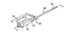
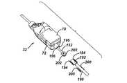
図1は符号30として概略的に示されているハンドピースを有する本発明によるコア・サンプリング用の生検器具を示している。このハンドピース30は片手で快適に保持することができ、片手で操作可能である。また、このハンドピース30はプローブ組立体32および着脱自在に接続しているホルスター34を含むことができる。さらに、プローブ組立体32は、第1の外側のチューブ40および第2の軸方向のチューブ42等により、真空供給源36に操作可能に接続できる。これら第1および第2のチューブ40,42は、シリコン・チューブ、PVCチューブまたはポリエチレン・チューブ等のような、柔軟で透明または半透明な材料により作成できる。このように透明な材料を使用することは各チューブ40,42の中を流れている物質の可視化を可能にする。 FIG. 1 shows a biopsy instrument for core sampling according to the present invention having a handpiece, shown schematically as 30. The
第1のチューブ40は多数の流体の供給源に接続するためのY字形コネクタ44を含むことができる。さらに、このY字形コネクタ44の第1の基端部は制御モジュール46の中の第1のソレノイド制御型の回転弁48まで延在でき、このY字形コネクタの第2の基端部は制御モジュール46の中の第2のソレノイド制御型の回転弁51まで延在可能である。この場合に、制御モジュール46の中の第1のソレノイド制御型の回転弁48は真空供給源36または圧縮空気供給源38のいずれかを外側のチューブ40に接続するために操作可能である。なお、本明細書において、圧縮空気は、大気圧と同等またはそれよりも高い空気の圧力を意味する。一例の構成において、弁48が作動すると、真空が真空供給源36からチューブ40まで供給され、弁48が作動していないと、圧縮空気供給源38からの加圧された空気がチューブ40を通して供給される。この場合に、上記弁48に付随しているソレノイドが、点線47により示されているように、制御モジュール46の中のマイクロプロセッサ49により制御可能である。このマイクロプロセッサ49はプローブ組立体32の中に移動可能に支持されているカッターの位置に基づいて自動的に弁48の位置を調節するために使用できる。一方、上記制御モジュール46の中の第2のソレノイド制御型の回転弁51は塩水供給源50(塩水供給用のバッグ、あるいは、塩水の加圧型貯蔵器等)をチューブ188に接続するか当該チューブ188の基端部を密閉するために使用できる。例えば、回転弁51は、ハンドピース30におけるスイッチを作動すると、塩水を供給するためにマイクロプロセッサ49により作動できる。さらに、この回転弁51が作動する場合に、外側のチューブ40の中における真空と塩水との相互作用を防ぐために上記第1の回転弁48が(マイクロプロセッサ49等により)自動的に停止できる。さらに、望まれる場合に、上記チューブ40の中へ注射器により直接塩水を注入可能にするために、ストップコック58をその外側の真空チューブ40に含むことができる。例えば、注射器による注入は、流体の通路を詰まらせている組織等のような、生じる可能性のある何らかの凝結物を排除するために、上記チューブの中の塩水の圧力を高めるために使用できる。 The
一例の実施形態において、軸方向の真空チューブ42は組織貯蔵組立体52の中を通してプローブ組立体32まで供給源36からの真空を伝達するために使用できる。この軸方向のチューブ42は切断の前に組織を側面の組織孔の中に脱出させることを補助するためにプローブ組立体32内のカッターの中を通して真空を供給できる。その後、切断を行なった後に、軸方向の配管42内の真空は、以下において詳述されているように、切断した組織サンプルをプローブ組立体32から組織貯蔵組立体52の中に引き込むことを補助するために使用できる。 In one example embodiment, the
ホルスター34はハンドピース30を制御モジュール46に操作可能に接続するための制御コード54、およびそのホルスターを駆動モーター45に接続している柔軟で回転可能な軸部55を含むことができる。電力供給源56は上記制御コード54を介してホルスター34に電力供給するための制御モジュール46にエネルギーを供給するために使用できる。また、スイッチ60はオペレーターが片手でハンドピース30を使用することを可能にするためにホルスターの上部外殻部62に取り付けられている。このような片手式の操作は、例えば、超音波画像化装置を保持するために、オペレーターの別の手を自由にすることを可能にする。また、各スイッチ60はカッターの動作を手動で始動させるための二位置ロッカー・スイッチ64を含むことができる(例えば、このロッカー・スイッチの前方への移動は組織サンプリングのためにカッターを前方(先端側)に移動し、このロッカー・スイッチの後方への移動はカッターを逆(基端側)の方向に作動する)。あるいは、上記カッターは制御モジュール46により自動的に作動できる。さらに、オペレーターが外側チューブ40の中への塩水の流れを必要に応じて作動させることを可能にするために付加的なスイッチ66をホルスター34に備えることができる(例えば、このスイッチ66は、当該スイッチ66が使用者により押されると、チューブ40に対して塩水の流れを供給するための弁51を操作するように構成できる)。 The
図2はホルスター34から分離されているプローブ組立体32を示している。このプローブ組立体32は上部外殻部70および下部外殻部72を含み、これらのそれぞれは、ポリカーボネート(polycarbonate)等のような、剛性で生体適合性のプラスチックにより射出成形できる。プローブ組立体32の最終的な組み立て時において、上部および下部の外殻部70,72は、超音波溶接、スナップ・ファスナー、締り嵌め、および接着剤による結合を含むが、限定を伴わない、種々のプラスチック部品を結合するために良く知られている多数の方法のいずれかにより接合エッジ部分74に沿って結合できる。 FIG. 2 shows the
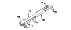
図3a、図3b、図3cおよび図4は上記プローブ組立体32を詳細に示している。図3aは基端側に後退しているカッター組立体およびキャリジを示している。図3bは部分的に進行しているカッター組立体およびキャリジを示している。また、図3cは先端側に進行しているカッター組立体およびキャリジを示している。図3a乃至図3cにおいて示されているように、上記プローブ組立体は所与の組織サンプルを得るために患者の皮膚の中に挿入するための、当該プローブ組立体32の先端部に配置されている、生検針80を含むことができる。この針80は細長い金属製のカニューレ82を含み、このカニューレ82は、(図5aにおいて示されているように)カッター100を受容するための上方カッター内孔部83等のような、上方の内孔部、および所与の流体の通路を形成するための下方内孔部84等のような、下方の内孔部を含むことができる。この場合に、カッター100は上記カニューレ82の中に配置でき、その内孔部83の中に同軸に配置できる。 3a, 3b, 3c and 4 show the
上記カニューレ82は、円形または卵形の形状の断面を含む、任意の適切な断面形状を有することができる。カニューレ82の先端部の近くおよび基端側は患者から切断される組織を受容するための側面(横方向)の組織受容ポート86である。針80の鋭利化された先端部分はカニューレ82の先端部に取り付けられている別のエンドピース90により形成できる。このエンドピース90の鋭利化された先端部分は、上記側面の組織受容ポートをサンプリングする組織の塊りの中に位置決めできるように、患者の皮膚を穴あけするために使用できる。エンドピース90は図示のように二面型で平坦な形状の先端部分、または患者の軟質組織を穿孔するために適している多数の別の形状を有することができる。 The
上記針80の基端部は、内部に貫通している長手方向のボア94、およびこのボアの広げられた中心部分の中に到る横方向の開口部96、を有するユニオン・スリーブ92に取り付けることができる。また、外側チューブ40の先端部はユニオン・スリーブ92の横方向の開口部96の中にしっかりと嵌合するように挿入できる。このような取り付けは下方の内孔部と外側のチューブ40との間における流体(気体または液体)の連通を可能にする。 The proximal end of the
細長い管状のカッターとすることのできる、カッター100は上方内孔部83の中に少なくとも部分的に配置することができ、この内孔部83の中において移動および回転するように支持できる。さらに、このカッター100は、先端側および基端側の両方の方向において移動可能になるように、上記針の内孔部84の中において支持できる。さらに、カッター100は側面の組織受容ポート86の全体を通して上方内孔部83の中に受容されている組織を切断するための鋭利化された先端部106を有することができる。さらに、カッター100は金属、ポリマー、セラミック、またはこれらの材料の組み合わせを、限定を伴わずに含む、任意の適当な材料により形成できる。また、カッター100は、側面の組織ポート86の全体を通して内孔部83の中に受容されている組織を切断するために、その先端部106が側面の組織ポート86の基端側の位置(図3aにおいて示されている)からその側面の組織ポート86の先端側の位置(図3cにおいて示されている)まで移動するように、適当な駆動組立体により内孔部83の中において移動できる。また、別の実施形態において、外部カッターが使用可能であり、この外部カッターは内側のカニューレ針と同軸に摺動し、この内側の針は側面の組織受容用ポートを含むことができる。 The
ユニオン・スリーブ92はカッター100と当該ユニオン・スリーブとの間の適当な整合を確実にするためにプローブの上方および下方の外殻部分70,72の間に支持されている。このカッター100は中空のチューブとすることができ、内孔部104がこのカッター100の長さ全体を通して軸方向に延在している。図4において示されているように、カッター100の基端部はカッター歯車110の軸方向のボアの中を貫通できる。このカッター歯車110は金属または高分子とすることができ、複数のカッター歯車の歯112を含む。また、カッター歯車110はカッター歯車の歯112に対して歯合するように設計されている複数の駆動歯車の歯116を有する回転駆動軸部114により駆動できる。さらに、駆動歯車の歯116は、図5a乃至図5cにおいて示されているように、カッター100がその最も基端側の位置から最も先端側の位置まで移動する時に、カッター歯車の歯112に対して係合するように駆動軸部114の長さに沿って延在できる。駆動歯車の歯116は駆動軸部114が回転して駆動する時にはいつでもカッター100を回転するためにカッター歯車の歯112に対して継続して係合できる。また、駆動軸部114は組織の切断のために上記カッターが組織受容ポート86の全体を通して先端側に前進する時にそのカッター100を回転する。この駆動軸部114は液晶ポリマー材料等のような剛性のエンジニアリング・プラスチックにより射出成形できる。あるいは、金属製または非金属の材料により製造できる。さらに、駆動軸部114は当該軸部から先端側に延出している第1の軸端部120を含む。この軸端部120は、プローブの下方外殻部分72の内側に成形されている支持面部122等により、そのプローブ外殻部分の中において回転するように支持されている。同様に、第2の軸端部124が回転駆動軸部114から基端側に延出していて、プローブの下方外殻部分72の内側に成形可能である第2の支持面部126の中に支持されている。また、回転軸部114がプローブ外殻部分72の中に取り付けられている場合の当該軸部114における回転の支持および可聴雑音の減衰を行なうために、O−リングおよびブッシュ(図示せず)をそれぞれの軸端部120,124に備えることができる。 A
図3a、図3b、図3cおよび図4において示されているように、駆動キャリジ134がカッター歯車110を保持するためにプローブ組立体32の中に備えられていて、そのカッター歯車および取り付けられているカッター100をその先端側および基端側の両方の方向への移動中に担持する。駆動キャリジ134は好ましくは剛性ポリマーにより成形されていて、軸方向に貫通している円筒形状のボア136を有している。さらに、一対のJ字形のフック状の伸長部分140が駆動キャリジ134の一方の側面から延出している。これらのフック状の伸長部分140は駆動キャリジ134の基端側および先端側の移動中にカッター歯車110およびカッター100の基端側および先端側の移動を行なうためにそのカッター歯車110のいずれかの側においてカッター100を回転可能に支持する。この場合に、上記フック状の伸長部分140はカッター歯車の歯112が駆動歯車の歯116に歯合するために適当な方向でカッター100およびカッター歯車110に整合する。 As shown in FIGS. 3 a, 3 b, 3 c and 4, a
駆動キャリジ134は移動軸部142において支持されている。この軸部142はカッター100および回転駆動軸部114に対して概ね平行に支持されている。この移動軸部142の回転は親ねじ型の駆動機構を採用することによりキャリジ134の移動(およびカッター歯車110およびカッター100の移動)を行なう。すなわち、この軸部142は、その外表面部において、親ねじ部分144等のような、外部親ねじのねじ山を含んでいる。このねじ山144はキャリジ134の中のボア136の中に延在している。さらに、このねじ山144はボア136の内表面部に設けられている内部の螺旋状のねじ付きの表面部分に係合している。従って、軸部142が回転すると、キャリジ134はこの軸部142のねじ付きの部分144に沿って移動する。さらに、上記のカッター歯車110およびカッター100がキャリジ134と共に移動する。また、上記軸部142の回転の方向を逆にすることにより、キャリジ134およびカッター100の移動の方向が逆になる。この移動軸部142は液晶ポリマー材料等のような剛性のエンジニアリング・プラスチックにより射出成形できるか、あるいは、金属製または非金属の材料により製造可能である。上記親ねじのねじ付き部分144を伴う移動軸部142は金型成形、機械加工、またはその他の処理により形成可能である。同様に、上記キャリジ134はボア136の中に内部の螺旋状のねじ山を含むように成形または機械加工できる。これにより、上記軸部142の回転は、カッター100がプローブ組立体32の中において移動するように、その軸部142の回転の方向に応じて、上記キャリジおよびカッター歯車110およびカッター100を先端側および基端側のそれぞれの方向に駆動する。また、カッター歯車110は、カッター100が駆動キャリジ134と同一方向に同一速度で移動するように、カッター100にしっかりと取り付けられている。 The
一例の実施形態において、親ねじのねじ山部分144の先端部および基端部において、ねじ山の有効ピッチ幅がゼロになるように、螺旋状のねじ山が切除されている。従って、このねじ山144の最も先端側の位置および最も基端側の位置においては、駆動キャリジ134がねじ山144から効果的に外れているので、軸部142の継続された回転にかかわらず、当該軸部142により積極的に駆動されなくなる。さらに、圧縮コイルばね150Aおよび150B(図3a乃至図3c)等のような、バイアス部材が上記ねじ山144の先端部および基端部の近くの軸部142上にそれぞれ配置されている。これらのばね150A/Bは、上記キャリジ134がねじ山144から外れると、そのキャリジ134を親ねじのねじ山144に対して係合状態に戻すようにバイアス力により付勢する。一方、軸部142が同一の方向に回転し続けていても、上記ゼロ・ピッチ幅のねじ山は、各ばね150A/Bとの組み合わせにおいて、キャリジ134および、それゆえ、カッター100をその軸部の端部において「惰性で動いている(freewheel)」状態にする。この場合に、上記軸部142のねじ付きの部分の基端部において、上記キャリジはばね150Aに係合する。また、軸部142のねじ付きの部分の先端部において、上記キャリジはばね150Bに係合する。さらに、このキャリジがねじ山144から外れると、ばね150Aまたは150Bはそのキャリジ134に係合して、そのキャリジ134を軸部142のねじ山144に対して係合状態に戻すように付勢し、この時点において、軸部142の継続されている回転が再びそのキャリジ134をねじ山144から外れさせる。従って、軸部142の回転が同一方向に維持されている限り、キャリジ134(およびカッター100)は「惰性で動き(freewheel)」続けるようになり、カッター106の先端部は、上記キャリジがばね150Aまたは150Bによりねじ山144の上に交互に付勢された後に軸部142の回転によりそのねじ山144から外れるので、基端側および先端側に短い距離だけ移動する。上記カッターが図3cにおいて示されている最も先端側の位置にある時に、そのカッターの先端部106は側面の組織ポート86の先端側に配置されており、ばね150Bはキャリジ134に係合し、そのキャリジ134がねじ山144から外れると、そのキャリジ134をねじ山144に対して係合するように繰り返して押し戻す。従って、カッター100は当該カッターの先端部106が、図3cにおいて示されている位置まで、組織を切断するために側面の組織ポート86を通過して先端側に移動するように前進した後に、軸部142の回転の方向が逆になるまで(例えば、図3aにおいて示されている位置まで基端側にカッター100を後退させる場合等のように)、当該軸部142の継続されている回転が上記先端部106の前後の振動、すなわち、基端側および先端側への短い距離の移動を生じる。このようなねじ山に対する係合、およびばね150Bの付勢力に対抗するねじ山144に対する係合からの離脱、に到るキャリジ134のわずかな移動はカッター100の先端部106をカニューレ82の中においてわずかな距離だけ繰り返して往復動させ、この距離はねじ山144のピッチにほぼ等しくすることができ、さらにこの距離は側面の組織ポート86を横切って上記カッターが移動する距離よりも短い。一方、カッターの往復移動は、以下において説明されているように、上記側面の組織ポートの先端側に配置されている少なくとも1つの流体の通路の交互の被覆および露出を行なうことができる。 In one example embodiment, the helical threads are cut off at the leading and proximal ends of the lead
上記親ねじのねじ山部分144のゼロ・ピッチ幅の各端部はカッター100の軸方向の移動に対する所定の停止部分を設けており、これにより、キャリジ134がそのねじ山の先端部および基端部に近づく時にそのキャリジ134(すなわち、カッター100)の速度を遅くする必要性が排除できる。このような所定の停止部分は軸部142に対するキャリジ134のために必要とされる位置決め精度を軽減して、所与の処置の初期化における較正時間を短縮する。また、上記移動軸部142の最も先端側および最も基端側の各位置におけるキャリジ134の惰性で動く状態は所与の処置中にその軸部を正確な回転数で回転させる必要性を排除する。むしろ、移動軸部142はキャリジ134が親ねじ144の全長を移動してゼロ・ピッチ幅のねじ山部分に到達することを保証するために少なくとも最小の巻き数だけ移動することのみを必要とする。加えて、上記キャリジ134の惰性で動く状態は上記装置を帰還させる必要性を排除しており、プローブ組立体32をホルスター34に最初に取り付けることなく患者の組織の中に挿入することを可能にしている。この場合に、プローブ組立体32が挿入された後に、ホルスター34が取り付けられて、サンプリングが開始できる。 Each end of the zero pitch width of the lead
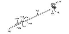
図4において示されているように、非回転式の後方チューブ152を備えることができ、このチューブ152はカッター歯車110のすぐ基端側のカッター100の基端部から基端側に延在できる。この後方チューブ152は中空にすることができ、カッター100と実質的に同一の内径を有することができ、当該カッターと同一の材料により構成できる。また、カッター100が上記後方チューブ152に対して回転することを可能にしながら当該後方チューブ152とカッター100との間に気密なシールを形成するために、これらのカッター100と後方チューブ152との間にシール154が配置できる。さらに、後方内孔部156が上記チューブ152の全長にわたり貫通していてカッター100の中の内孔部104に対して整合可能である。この後方内孔部156は切り取った組織サンプルを上記内孔部104からプローブ組立体32の中を通して組織貯蔵組立体52に移送する。すなわち、これらの内孔部104および後方内孔部156は、組織サンプルを移送するために、連続的な概ね直線状の塞がれていない通路を上記の組織受容ポート86と組織貯蔵組立体52との間に形成するために軸方向に整合している。上記のカッター100およびチューブ152のそれぞれの内表面部は切り取った組織サンプルの基端側への移送を補助するために液体潤滑性の材料により被覆できる。 As shown in FIG. 4, a non-rotating
さらに、外側伸長部分158を備えていてもよく、外側伸長部分158は、キャリジ134を駆動する場合に上記後方チューブ152を固定するために、その後方チューブ152により支持され、当該チューブ152から先端側に延びる。この伸長部分158は、上記チューブ152がカッター100と共に移動して、各内孔部104,156を切断工程の全体を通して液密式の連通状態に維持するように、チューブ152をキャリジ134に接続する。 Further, an
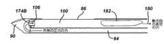
図5a乃至図5dは切断工程中のカッター100の移動の単純化された概略図を示している。図5aにおいて示されているように、切断工程において最初に、カッター100は最も基端側の位置に配置されており、その先端側の切断端部106は側面の組織ポート86の最も基端側のエッジ部分よりも基端側で内孔部分割部材170の基端部の近くに配置されている。切断工程が開始すると、外側の真空の力(矢印176により示されている)が下方の内孔部84の中に供給可能になる。この真空の力176は上記ユニオン・スリーブ92により形成される流路を通して上記真空供給源36からチューブ40を介して下方の内孔部84に伝達できる。 Figures 5a to 5d show a simplified schematic of the movement of the
上記マイクロプロセッサ49は、スイッチ64が針80の中においてカッター100を先端側に移動し始めるために使用者により作動されると、上記の真空の力176を供給するために弁48を作動させるように使用できる。この外側の真空の力176は組織受容ポート86の下に配置されている各流体通路172および当該ポート86の先端側に配置されている1つ以上の流体通路174を通してそのポート86に連通している。図5cにおいて、流体通路174Aがポート86の先端側に配置されていて当該ポート86から周囲に沿って約180度にわたり離間して示されている。また、図5dにおいて、流体通路174Bが生検プローブの先端側のエンドピース90の中においてポート86の先端側に配置されて示されている。これら両方の流体通路174Aおよび174Bは上記下方の内孔部84および上方の内孔部83の間の流体の連通を行なうことができる。 The
上記外側の真空の力176は組織サンプル182を組織ポート86の中に引き込むためにカッター内孔部104の中を通る軸方向の真空の力180との組み合わせにおいて使用できる。組織サンプル182がポート86の中に引き込まれた後に、その組織サンプルを周囲の組織から切断するためにカッター100が回転するのと同時に先端側に移動できるようになる。このカッター100が前進している間に、上記の真空の力176,180は、サンプルが切断される時に、その組織サンプルをカッター内孔部の中に引き込むために、下方の内孔部84およびカッター内孔部104の中を通してそれぞれ維持できる。図5bにおいて示されているように、カッター100が前進して各流体通路172を横切って摺動すると、それぞれの穴を介する外側の真空を連続的に遮断する。 The
カッター100が、図5cにおいて示されているように、最も先端側の位置に到達すると、各流体通路172はそのカッターにより完全に遮断できる。この切断工程の時点において、カッターの回転を維持することができ、カッターは上述したように「惰性で移動している(freewheel)」状態になり、このカッター100の先端部106は、交互に振動している様式で、基端側および先端側に移動する。このカッター100が惰性で移動している時に、このカッターは移動軸部142の回転速度にほぼ対応する周波数で親ねじのねじ山144のピッチにほぼ等しい距離で先端側および基端側に振動できる。さらに、このカッター100がその最も先端側の位置において惰性で移動するに従って、このカッターがこれらの流体通路174Aを交互に被覆および露出する(すなわち、開口および閉鎖する)ように、上記内孔部分割部材170の中に1つ以上の流体通路174Aを配置してもよい。通路174Aが開口している状態で、下方の内孔部84は、各通路172の遮断にかかわらず、分割部材170を介するカッター内孔部104に対する流体の伝達状態を維持する。このような通路174Aの上におけるカッター100の反復性の移動はその通路174Aを遮断するか詰まらせる可能性のあるあらゆる組織を除去して、その通路174Aの中の流体の連通状態を維持することを補助できる。 When the
先端側のエンドピース90の中の流体通路174Bは流体通路174Aの代わりにまたはこれとの組み合わせにおいて使用できる。例えば、この流体通路174Bは通路174Aがカッター100により被覆されている時に下方の内孔部84と上方の内孔部83との間において流体の連通を行なうことができる。 The
上記カッター100がその最も先端側の位置に到達して惰性で移動し始めてから所定量の時間の経過後に、外側の真空の力176を図5cにおいて矢印により示されているような前方に向かう加圧された空気(大気圧かこれよりも高い)に換えるために、回転弁48におけるソレノイドがマイクロプロセッサ49により動力源を断たれるか他の方法で制御できる。この加圧空気は外側チューブ40から内孔部84に放出される。各ポート穴172がカッター100により閉じられている状態において、上記の加圧空気はサンプル182の先端側の面に対して力を加えるために流体通路174A(および/または174B)を通して上方の内孔部83に連通している。このサンプル182の先端側の面に作用する力はカッター100の内孔部104を通して供給される軸方向の真空の力180との組み合わせにおいて作用できる。このようなカッター100の内孔部104を介して供給される真空により与えられる真空の「引張力(pull)」との組み合わせにおいてサンプル182の先端側の面に作用する力により加えられる押出力が、図5dにおいて示されているように、サンプル182をカッター100の内孔部104の中を通して移動するために使用できる。あるいは、上記サンプル182の先端側の面に力を加えるために加圧空気を使用する代わりに、塩水等のような、加圧された液体を、そのサンプル182の先端側の面に力を加えるために、下方の内孔部84および流体通路174Aおよび/または174Bを通して送り込むことができる。上記カッター100は、その外側カニューレおよび側面のポート86の周囲の組織が流体に対して曝されないように、流体(気体または液体)の流れに対して側面の組織ポート86を閉鎖する。 After a predetermined amount of time has elapsed since the
組織サンプル182がプローブ組立体32の中を通してサンプル収集組立体52に向かって移動する時に、カッター100はその最も先端側の位置に維持できる。あるいは、このカッター100は次の切断工程の準備においてその初期の位置に向かって組織ポート86の全体を通して後退できる。カッター100が完全に後退して、組織サンプルが組織貯蔵組立体52に移動した後に、外側の真空の力176が次の組織サンプルをポート86の中に引き込むために内孔部84を介して再び供給される。このカッター100の移動中に、このカッターは内孔部83を内孔部84から分離するための分割部材170と共に動作できる。 As the
切断工程の間に、上記カッター100は側面の組織受容用ポート86のわずかに基端側の位置からその受容用ポートのわずかに先端側の位置まで移動する。これにより、切断された組織サンプルは、一部の従来の装置におけるように、ノック−アウト・ピンによりサンプルを排出するために針80を通してカッターを(サンプルがそのカッターの先端部の中に担持されている状態で)基端側に移動する代わりに、カッター100の内孔部104の長さ全体を通してそのカッター100の基端部から送り出される。従って、この切断ストロークの長さは側面の組織ポート86の長さよりもわずかに長くなるように減少できる。この減少されたストロークの長さにより、カッター100の先端部(ならびにカッター100の長さ)は切断工程の全体を通して針80の中に維持できるので、プローブ・ハウジングの中および針80の基端側にカッターの全長を適合させる必要が無くなる。加えて、上記の減少された切断ストロークの長さは、移動軸部142が組織受容ポート86の長さよりもわずかに長い距離だけ上記カッターを移動することだけを必要とするので、当該軸部142の必要とされる長さも減少する。さらに、この移動軸部の長さの減少、およびカッターの長さをプローブ・ハウジングの中に適合させる必要性の排除はハンドピース30の長さを減少することを可能にする。また、針80の中を通してカッターを前進および後退させるために必要とされる時間を減少する短小化された切断ストロークにより、それぞれの組織サンプルを得るための時間も本発明において短縮される。加えて、カッター100は組織受容ポート86のわずかに基端側の位置に後退するだけであるので、内孔部分割部材170は上記針の全長に通してではなく、上記カッターの最も基端側の位置まで延在するように形成できる。さらに、この分割部材170の長さの減少は針80の必要とされる材料および製造コストを減少する。 During the cutting process, the
上述したように、流体通路174A/174Bはまた、図5cおよび図5dにおいて示されているように、切断された組織サンプルの先端側の面に塩水を供給するために使用することもできる。この塩水は組織サンプルに対して押出力を加えるために使用できるので、カッター内孔部104の中に基端側に組織サンプルを移動することにおいて補助できる。このような塩水の急な流れを供給するために、塩水供給バッグ50からの配管が制御モジュール46による回転弁51を介してY字形コネクタ44に到り外側チューブ40を通して内孔部84に到達している。一例の実施形態において、ボタンをハンドピース30に備えることができ、カッターがその最も先端側の位置において惰性で移動している間にこのボタンが押されると、弁51が塩水50を外側チューブ40に接続するために作動されるようになっている。この場合に、サンプリングの処置の前に、上記塩水システムは、上記回転弁51を作動して真空供給源36からの真空が塩水を配管188の中に引き込むことを可能にすることにより準備できる。その後、この塩水はY字形コネクタ44まで配管188を充たす。オペレーターが上記処置の間にハンドピースのボタンを押すと、塩水がY字形コネクタ44から、外側チューブ40の中を通り、内孔部84の中に流れて組織サンプル182に供給される。その後、回転弁51の電力が断たれると、配管188が密閉されて、内孔部84への塩水の流れが停止する。 As described above, the fluid passages 174A / 174B can also be used to supply saline to the distal surface of the cut tissue sample, as shown in FIGS. 5c and 5d. Since this salt water can be used to apply a pushing force to the tissue sample, it can assist in moving the tissue sample proximally into the cutter bore 104. In order to supply such a rapid flow of salt water, the piping from the salt
別の実施形態において、塩水は全ての切断工程の間に内孔部84に対して自動的に供給できる。この実施形態においては、ハンドピースのボタンは塩水を操作するために必要でない。むしろ、マイクロプロセッサ49が、カッター100が切断工程中に針80の中の最も先端側の位置に到達してから指定された時間に、回転弁51を自動的に作動させて、そのカッターが指定された基端側の位置まで後退した時にその弁を停止させる。さらに、切断工程中のカッターの軸方向の位置に基づいて回転弁51を作動させるために位置センサーをホルスター34または制御モジュール46と共に組み込むことができる。従って、カッター100の位置は、例えば、当該カッターが各切断工程中に前進および後退する時等において、回転弁51を自動的に作動および停止させる。 In another embodiment, brine can be automatically supplied to the
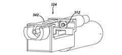
図4において示されているように、駆動スロット132を、モーター駆動軸部の中の類似形状の駆動スロット、またはその他のホルスター34からの回転駆動力の入力、に対してインターフェイスにより接続するために、軸部114の基端部124の中に形成できる。あるいは、図6において示されているように、星形の形状のインターフェイス130を駆動軸部114の第2の軸端部124の中に成形できる。この星形のインターフェイス130は駆動軸部114を回転するためにホルスター34の回転駆動軸部に備えることができる類似形状のオス形のインターフェイスに対して係合するように備えることができる。あるいは、このメス形の星形のインターフェイス130をホルスター34からの駆動軸部の中に成形して、類似形状のオス形のインターフェイスを駆動軸部114の中に形成することも可能である。このような星形のインターフェイス130の使用、または上記回転駆動軸部の中に成形されたその他の類似の種類のインターフェイスの使用は、駆動の結合のために必要とされる軸方向の長さを最小にする。さらに、この駆動の結合の長さを減少することはプローブ32の全体の長さを減少する。 As shown in FIG. 4, for connecting the
図7および図8は本発明における別の実施形態を示しており、この実施形態において、カッター100および後方チューブ152はプローブ組立体32から取り外し可能であり、カッター100はプローブ組立体32を分解することなく当該プローブ組立体32に対して繰り返して取り外しおよび再挿入することができるようになっている。このカッター100の取り外し(部分的または完全な取り外しのいずれも)は、当該カッター100が金属により形成されていて、プローブ32と共に用いられている画像化装置が磁気共鳴画像(MRI)装置である場合に等において、有利になると考えられる。なお、図7および図8において、後方チューブ152の基端側の部分は示されていない。 7 and 8 illustrate another embodiment of the present invention, in which the
図7および図8において示されている実施形態において、カッター100および後方チューブ152は、当該カッターが後方チューブ152(このチューブ152は回転しないように支持できる)に対して回転できるように、カッター歯車110のすぐ基端側におけるシール部分154において結合できる。さらに、カッター解放レバー160が後方チューブ152の上に支持でき、当該チューブ152から突出できる。この図示されているような放出レバー160はキャリジ134に向かって先端側に延出している端部162を含む。この端部162の中の横方向のスロット164は、キャリジ134の基端側のフック状の伸張部分140に固定して取り付けることのできるディスク部分166等のような、キャリジ134に付随している部分に係合するように形付けられて寸法付けられている。このスロット164がディスク166に係合している間は、カッター100および後方チューブ152はキャリジ134と共に移動する。さらに、カッター100の基端部の近くに配置されているスプライン部分168はカッター100およびカッター歯車110が一緒に回転することを確実にするためにカッター歯車110の内径部分における相補的なスプライン部分に対して係合するために使用できる。 In the embodiment shown in FIGS. 7 and 8, the
切断工程の前に画像化する等のために、プローブ組立体32からカッター100およびチューブ152を取り外すために、上記解放レバー160の基端部がチューブ152の方向に押し下げられる。この押し下げ動作はスロット164をディスク166から外して、カッター100およびチューブ152をキャリジ134およびカッター歯車110の両方から解放する。図8において示されているように、チューブ152およびカッター100が解放されると、これらのチューブおよびカッターはカッター歯車のボアの中を通して基端側に引っ張ってプローブ組立体32の基端部から取り出すことができるようになる。また、カッター100およびチューブ152を再挿入するためには、これらのチューブおよびカッターをシール部分154において接続して、カッターがカッター歯車のボアおよびユニオン・スリーブのボア94の中を通してカニューレ82の中に再び延在するように、上記の組み合わせがプローブ組立体32の基端部の中に挿入される。この場合に、カッター100およびチューブ152は端部162のスロット164がディスク166の上に再び掛かるまでプローブ組立体32の中を通して先端側に押し込まれる。 To remove the
上記カッター100はプローブ組立体32の基端部の中の開口部を通して当該プローブ組立体32に対して繰り返して取り外しおよび再挿入することができる。これにより、上記の組織受容ポート86をサンプリングする組織の中に位置決めして、カッター100をプローブ組立体32から取り外し、生検部位をMRIの使用等により画像化して、カッターをプローブ組立体32の中に挿入し、側面の組織ポート86の中に受容されている組織をカッター100により切断することができる。なお、上記のプローブ組立体からカッターを取り外す工程は組織ポート86をサンプリングする組織の中に位置決めする前または後に行なうことができる。加えて、針80を組織から除去する前または後のいずれにおいても、カッターは組織サンプルが切断された後に取り外すことが可能である。 The
図9aおよび図9bにおいて示されているように、分割部材170は針80の内部を上方および下方の内孔部83/84に分離するためにカニューレ82の先端部の中に挿入できる。図9aおよび図9bにおいて示されている実施形態において、分割部材170は組織受容ポート86のすぐ基端側の位置までカニューレ82の中を通して軸方向に延在している。この分割部材170の基端部は、上記カッターおよび当該分割部材が結合して上方および下方の内孔部を分離するように、カッター100の最も基端側の位置に一致させることができる。あるいは、分割部材170は針80の全長を通して軸方向に延在できる。図9aにおいて示されているように、分割部材170は、カッターがカニューレ82の中を移動する時にそのカッターが分割部材の表面に沿って摺動することを可能にするように、そのカッター100の外周にぴったりと一致する湾曲状の表面を含むことができる。さらに、複数の流体通路の穴172が組織受容ポート86の下方の分割部材170に形成できる(このポート86から約180度離間している)。これらの流体通路172は、切り取られた組織部分が内孔部の中を通過することを妨げながら、各内孔部83および84(および組織受容ポート86)の間の流体の連通を可能にするように寸法付けることができる。また、上記分割部材170は組織受容ポート86の先端側の1つ以上の流体通路174も含むことができ、これらの通路174を通して、圧縮された気体(例えば、空気)または液体(例えば、塩水)が、上記カッター100がその最も先端側の位置にあって組織受容ポート86を閉鎖している間に、カッター内孔部104の中に存在している組織サンプルの先端側の面に供給できる。このように、カッター100がその最も先端側の位置にあって組織受容ポート86を閉鎖していることにより、組織サンプルは、カニューレ82の周囲の組織を液体に曝すことなく、カッター100の中を通して押し動かすことができる。この場合に、分割部材170はカニューレ82と同一の材料により形成でき、この分割部材の長手方向のエッジ部分はカニューレの内径部分に溶接またはその他の方法で永久的に固定できる。 As shown in FIGS. 9a and 9b, the
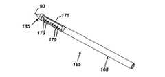
図10および図11は上記プローブ組立体32と共に使用するために適している生検針に対応する別の実施形態を示している。この針は、符号165により示されており、孔部品、組織穿孔部品、およびチューブ部品により組み立てることができる。この実施形態において、チューブ部品168は内部を貫通している内孔部173を有するカニューレ171、およびチューブの先端部の近くの組織受容用の孔175を有している。孔部品177は孔178および流体通路179を含む。また、組織穿孔部品90は上記孔部品にインサート成形できるか、接着剤またはその他の適当な結合手段等により、当該孔部品に機械的に固定できる。 10 and 11 show another embodiment corresponding to a biopsy needle that is suitable for use with the
図12および図13において詳細に示されているように、孔部品177は組織受容用の孔175と実質的に同一の長さの上方開口部178を伴う半管状の形状を有することができる。開口部178は上記2個の部品168,177が組み合わされる時に組織受容用の孔175に対して整合する。複数の流体通路179が開口部178の下方の孔部品177の下面部169に形成されている。この下面部169は針165が組み立てられる時に下方の内孔部を形成するための分割部材を形成できる。さらに、1つ以上の流体通路181を、上記針の各部品が組み立てられる時に組織受容用の孔175の先端側になるように、開口部178の先端側に備えることができる。各通路179および181は、針の各部品168,177が組み合わされると、下方の内孔部から上方の内孔部に加圧された流体(例えば、空気および/または塩水)の流れの連通をそれぞれ行なう。さらに、一対の係合用のボス183を備えて上記孔部品177をチューブ部品168に取り付けるために当該孔部品177の基端部から延出させることができる。針165を組み立てるために、孔部品177は、各ボス183がチューブ部品168の内径部分における相補的な溝または穴に係合するまで、カニューレ171の先端部の中に挿入される。このそれぞれのボスと溝との間の係合は孔部品177をチューブ部品168の中に係止する。加えて、針165がプローブ組立体32の中に組み合わされる時に、チューブ部品168の中の各ボス183よりも先端側に延出しているカッター100の部分が、孔部品177がチューブ部品168から分離することを、さらに防ぐことができる。また、円周上のリップ部分185を孔部品177に設けることができる。このリップ部分185は、上記孔部品がチューブ部品に組み合わされる時にそのチューブ部品168の先端部に対応する支持面を備えることができる。 As shown in detail in FIGS. 12 and 13, the
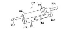
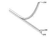
再び図5において、組織サンプルがカッター100の内孔部104の中に入ると、軸方向の真空の力180がサンプルをカッター100の中を通して基端側に引っ張ってプローブ組立体32から組織貯蔵組立体52の中に送り込むために作用できる。第1の実施形態において、組織貯蔵組立体52は、図14において示されているような、連続組織堆積組立体190を含む。この連続組織堆積組立体190の中において、多数の組織サンプルが、柔軟なチューブ等の中に、端面を重ね合わせる構成で次々に堆積される。その後、これらのサンプルはそのチューブから個々に取り出してその処置中にリアルタイムで調べることができ、あるいは、その処置の終了時までチューブの中に留めておいて一度に全てを取り出すことも可能である。上記連続組織組立体190の先端部はプローブ組立体32に二重操縦式の接続機構を介して(この連続組織貯蔵組立体190がプローブ組立体から放出可能になるように)着脱自在に接続できると共に、この組立体190の基端部は、図1において示されている真空供給源36等のような、真空供給源にチューブ42を介して着脱自在に接続できる。 Referring again to FIG. 5, when the tissue sample enters the
図15aおよび図15bにおいて示されている実施形態において、上記連続組織組立体190の先端部における上方コネクタ192は一対のスナップ・ファスナー194を含む。これらのファスナー194は、プローブの下方外殻部分72の基端部の一部分の中に形成できる一対のノッチ部分等のような、上記プローブ組立体の基端部に配置されている一対のファスナー係合部分196に係合する。これらのファスナー194が、図15aにおいて示されているように、各部分196に係合すると、連続組織組立体190の上方の部分がプローブ・ハウジングに取り付けられる。 In the embodiment shown in FIGS. 15 a and 15 b, the
同様に上記連続組織組立体190の先端部における、第2の下方のコネクタ198は、類似の一対のスナップ・ファスナー200を含むことができる。これらの下方のスナップ・ファスナー200は図15bにおいてプローブ組立体32の中の基端側の開口部から延出して示されている後方チューブ152の基端部における一対の係合用の部分202に係合する。さらに、上記後方チューブ152の先端部は図8において示されているようにキャリジ134に結合できる。上記下方のスナップ・ファスナー200が、図15bにおいて示されているような、ノッチ部分202に係合すると、連続組織組立体190の下方の部分が駆動キャリジ134の移動と共に先端側および基端側に移動するようになる。このようにして上方コネクタ192および下方コネクタ198の両方がプローブ組立体32に取り付けられると、連続組織組立体190の下方の部分が切断工程中にこの組立体の固定されている上方の部分に対して移動するようになる。一方、上記連続組織組立体190をプローブ組立体32から分離するためには、上記スナップ・ファスナー194,200のそれぞれ前方の端部を対応しているノッチ部分196,202から分離するために、これらのスナップ・ファスナーの対のそれぞれがその先端部において内側に押される。このようにして、各ファスナーが分離された後に、連続組織組立体190はプローブ組立体32から分離できるようになる。 Similarly, the second
図14および図16において示されているように、連続組織組立体190は軸方向に貫通している二重式の内孔部を有するサンプル貯蔵チューブ206を含む。これらの二重式の内孔部は概ね平行にできる。このチューブ206は塩化ポリビニルまたはその他の類似の種類の柔軟で不溶性の材料により構成できる。また、この貯蔵チューブ206に対して、塩化ポリビニル等のような、透明な材料を使用することにより、貯蔵されている組織サンプルがチューブの外側から見えるようになる。 As shown in FIGS. 14 and 16, the
上記チューブ206はその2個の内孔部を分離するための長手方向に沿って延在している中心壁部の分割部材を含むことができる。このチューブ206はカッター内孔部104を通して上記組立体に吸引されている組織サンプル204を移動して貯蔵するための、堆積用の内孔部210等のような、第1の内孔部を有することができる。この組織堆積用の内孔部210は下方コネクタ198により後方チューブ152の基端部に着脱自在に接続できる。上述したように、上記ファスナー200が各部分202に係合すると、組織堆積用の内孔部210が後方チューブの内孔部156に対して軸方向に整合して、組織受容ポート86から組織堆積用の内孔部210の中への組織サンプル204の移動のための連続的で遮られていない通路を形成することができる。 The
組織サンプル204が組織堆積用の内孔部210の中に入ると、これらのサンプルは、これらのサンプルの順序(これらのサンプルが生検部位から得られる順序)が維持されながらこれらのサンプルが組織堆積用の内孔部210の中に貯蔵されるように、図16において示されているような、端面を重ね合わせる構成で連続的に次々に堆積する。さらに、最初のまたは最も早期のサンプルが組織内孔部の中を通して完全に、さらに真空システム36の中に、移動することを防ぐために、組織内孔部210の基端部における組織回収機構260の中に組織停止部分を配置することができる。さらに、上記チューブ206は、切断された組織サンプル204をカッター100および後方チューブ152の中を通して組織堆積用の内孔部210の中に引き込むことができるように、後方チューブ152およびカッター100の中を通る真空のための伝達経路を形成するために、第2の内孔部、すなわち、組織堆積用の真空内孔部214を有することができる。この組織堆積用の真空内孔部214の基端部は外側の連結ポート216を介して真空供給源36に着脱自在に接続できる。 As the
図17においてさらに詳細に示されているように、各内孔部214と210との間に流れの連通経路を形成するために、これらの内孔部214と内孔部210との間におけるチューブ206の中心壁部の分割部材の中に、複数の小さな穴220を設けることができる。これらの穴220は、カッター100の内孔部104の中に真空を供給するために、供給源36からの真空が内孔部214から内孔部210の中に伝達されることを可能にする。また、上記の穴220は好ましくはチューブ206の長手軸に沿って離間していて、0.1乃至4センチメートルの範囲内の距離で分離している。さらに、これらの穴220はチューブ206の長手軸に対して所与の角度で配向することも可能である。このような各穴220における角度は、内孔部210の中に開口しているこれらの穴220のエッジ部分が、先端側の方向における組織サンプルの移動を阻止するが、真空供給源36により供給される真空の力の下で組織サンプルが内孔部210の中において基端側に移動することを可能にすることを補助できると言う点において、機械的なダイオードとして機能できる。これにより、組織サンプルは、当該組織サンプルが組織回収機構260の中の組織停止部分または先行している組織サンプルのいずれかに接触するまで、内孔部210の中を通して基端側に摺動し続けるようになる。 As shown in more detail in FIG. 17, a tube between these
上記真空穴220はドリルまたはその他の適当な器具の鋭利化された先端部分によるチューブ206の上面部の中へのボーリングにより上記の各内孔部210,214の間に形成できる。このドリルの刃の先端部分またはその他のボーリング器具は上記2つの内孔部を分離しているチューブ206の中心の壁部を穿孔するために真空内孔部214の中を通過して送り込むことができる。図14において示されているように、外側スリーブ228は上記真空伝達用の穴220の形成後にチューブ206の表面に固定して取り付けられている。この外側チューブ228は接着剤またはその他の適当な種類の取付機構によりチューブ206に取り付けることができる。また、この外側スリーブ228は上記真空伝達用の穴220を形成するために使用する開口部の上から、これらの開口部を密閉して、これらの開口部を通して真空内孔部214から真空が漏れることを防ぐために、サンプル・チューブ206に取り付けられている。この外側スリーブ228の先端部は上方コネクタ192に接続するために真空内孔部214の先端部から先に延出するように形成できる。この場合に、真空内孔部214は外側スリーブ228と上方コネクタ192との間の接続によりプローブ組立体32に取り付けられる。 The
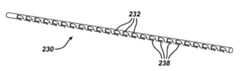
組織サンプル204が内孔部210の中に貯蔵されると、これらのサンプル204の堆積物の長さが内孔部210の中において先端側に増加する。従って、これらのサンプル204は、当該サンプルの堆積物が内孔部210の中において先端側に延びるのに従って、各真空穴220を通る流れの連通を遮断するか別の様式で制限するようになる。図16において、移動用の柔軟な棒材230が内孔部214の中において少なくとも部分的に配置されている状態で示されている。この棒材230は各真空穴220の少なくとも一部を選択的に被覆するか別の様式で遮断するために内孔部214の中を通して軸方向に延在できる。その後、真空内孔部の中の各真空穴220を選択的に露出するために、棒材230の軸方向の移動等により、この棒材230を操縦することができる。例えば、それぞれの切断工程中に、棒材230は、追加のサンプルが内孔部210の中に貯蔵されるのに従って、追加の真空穴220を露出させるかその他の様式で遮断解除/開口するために、真空穴214の中において先端側に前進できる。この棒材230の移動は、付加的な組織サンプルが内孔部210の中の組織サンプルの堆積物に追加されるのに従って、各内孔部210と214との間の流れの連通を行なうために、所定数の真空穴220を開口状態に維持する。このことは多数の切断工程を通してカッター内孔部104の中において一貫している真空の力を供給することを補助できる。初期において、柔軟な棒材230は、当該棒材230が、上記の穴220の、全部ではないが、大多数を被覆するかその他の様式で遮断するように、内孔部214の中において軸方向に並置されるように、その内孔部214の中に挿入できる。例えば、内孔部214の中に何らかのサンプルを貯蔵する前に、棒材230は組織受容ポート86の長さよりもわずかに長い所与の距離で真空内孔部214の中の先端側に並置できる。このように、棒材230を内孔部210の中に先端側に並置することは、カッター100が組織のサンプリングの前にその完全に基端側の位置にある時に、組織受容ポート86に対して軸方向の真空の力180を伝達するために初期的な組の穴220が露出されることを確実にする。この露出された穴220を通して伝達される軸方向の真空の力は、切断の前に、組織を受容ポート86の中に脱出させると共に、切断の後に、その組織サンプルを組織内孔部210の中に基端側に引き込むことを補助する。組織サンプルが組織内孔部210の中に引き込まれて堆積すると、この組織サンプルはそれまでに露出されていた真空穴220を遮断して、真空が組織内孔部の中に通じることを妨げる。この場合に、上記棒材230は、その最も新しく得られた組織サンプルのすぐ先端側に追加の真空穴220を露出させるために、組織受容ポート86の長さよりもわずかに長い所定の距離だけ先端側に選択的に移動できる。この棒材230は、以下においてさらに説明されているように、プローブ組立体32の中における駆動キャリジ134の移動により、先端側に自動的に前進することに適合できる。これらの新しく露出された真空穴220は次の切断工程において組織内孔部210の中への真空の力180の伝達を継続する。 As
棒材230は、テフロン(Teflon)(登録商標)等のようなフルオロポリマー樹脂の材料、または低い摩擦係数を有するその他の適当な柔軟性の材料により形成できる。この棒材230は真空内孔部214の内径にぴったりと一致するように寸法付けおよび形付けできる。このような棒材230と真空内孔部214との間の密接な嵌合、ならびに、この棒材の低い摩擦特性は、この棒材が上記内孔部の先端部を通して真空の力の損失を全くともなわずにその真空内孔部の中において容易に移動することを可能にする。 The
上記棒材230の先端部231は外側スリーブ228の中の開口部234を通して真空内孔部214の外側に延出している。この棒材230が先端側に前進すると、この棒材はさらに開口部234を通して真空内孔部214から外に移動する。この場合に、棒材230の柔軟性は、この棒材が継続的に先端側に前進すると、当該棒材が外側スリーブ228の中の開口部234から曲がって出ることを可能にして、実質的に全体の棒材が多数の切断工程の経過において真空内孔部214から移動して出ることを可能にしている。図18においてさらに詳細に示されているように、棒材230は実質的に当該棒材の長さに沿って長手方向に離間している複数の側面のラチェット歯232を含むことができる。これらの歯232は真空内孔部214の中を通して棒材230を把持して前進させるための機構を形成している。この棒材230はまた複数の下面のラチェット歯238も含むことができる。 The
上記棒材230は歯部232と、図19においてさらに詳細に示されている、往復動式の部材242におけるつめ型のラッチ機構240との間の相互作用により真空内孔部214の中において先端側に前進することができる。上記往復動式の部材242は下方コネクタ198の上に支持することができ、カッター100が前進および後退するのに従って往復動する。また、往復動式の部材242は軸方向に延在しているスロット244により分離されている基端側に延出している部分243を伴う分枝状の基端部を有することができる。さらに、傾斜した表面部分246がスロット244の先端部において各部分243の間に形成できる。この傾斜した表面部分246は、棒材230が真空内孔部214からラチェットによる係合により脱出する時に、開口部234を通りチューブ206の外表面部に沿って棒材230の先端部231を偏向させるために役立つことができる。さらに、上記棒材230が溝部の中に延在している時に、その棒材230における側部のラチェット歯232に係合するためにそのスロット244に面している各部分243の側面から延出するように単一方向係合式のつめ250を形成できる。これらのつめ250とラチェット歯232との間の係合が棒材230を真空内孔部214の中を通して先端側に前進させる。 The
上記往復動式の部材242の先端部は、各切断工程中に、下方コネクタ198、キャリジ134、およびカッター100と共に移動するために下方コネクタ198に固定できる。これにより、駆動キャリジ134がカッター100を受容ポート86の中に移動するために切断工程の開始時に先端側に前進すると、往復動式の部材242も先端側に前進する。さらに、この往復動式の部材242が前進すると、溝部244の中のつめ250が、棒材230をその往復動式の部材と共に先端側に引っ張るために、内孔部214の中の棒材230における側面の歯部232に係合する。この棒材230が内孔部214の中を先端側に移動すると、追加の真空穴220が露出される。その後、キャリジ134の方向が逆になると、カッター100は受容ポート86から後退し、往復動式の部材242は固定されている真空内孔部214に対して基端側の方向に移動する。さらに、往復動式の部材242が基端側に移動すると、柔軟な棒材230の下面に配置されている単一方向式の下面のラチェット歯部238が、図17において示されているように、真空内孔部214の中の各真空穴220に係合する。このラチェット歯部と各穴220との間の係合は棒材230が真空内孔部214の中において基端側に移動することを阻止する。さらに、上記のつめ250が棒材230に対して基端側に移動すると、これらのつめは棒材230における次の基端側の組のラチェット歯部232に係合する。この次の組のラチェット歯部232に対する係合は、駆動キャリジ134が追加の真空伝達穴220を露出させるために次の切断工程中において先端側に前進する時に、棒材230を再び先端側に前進させる。さらに、上記のキャリジおよびカッターの組立体が組織内においてプローブ組立体32を伴わずに前進および後退したことにより、柔軟な棒材230が組織サンプル204に対して過度に先端側に前進した場合には、この柔軟な棒材230は、各ラチェット歯部232および238を離脱させてその柔軟な棒材230が真空内孔部214の中において基端側に再位置決めされることを可能にするために、その長手軸の回りに1回転の一部分だけ回転できる。 The tip of the reciprocating
図示されていない別の実施形態において、上記の柔軟な棒材230は、駆動キャリジ134が組織の切断に続いて基端側に後退する時に、真空内孔部214の中において先端側に前進できる。このような実施形態において、駆動キャリジが後退すると、ケーブルが柔軟な棒材を先端側に引っ張るように、例えば、プーリーの周りに180°だけ延在しているケーブル等のような、逆転機構が利用可能である。 In another embodiment not shown, the
図19において示されているように、下方コネクタ198はサンプル・チューブ206の組織内孔部分を後方チューブ152に接続するための軸方向に延在しているボア252を含む。上記の連続組織組立体190が下方コネクタ198によりプローブ組立体32に接続されると、組織内孔部210、ボア252、および後方チューブの内孔部156は、カッター110および後方チューブ152から内孔部210に到る組織サンプルの吸引のための遮られていない通路を形成するために、概ね同軸に整合される。 As shown in FIG. 19, the
図20は各コネクタ192,198および内孔部210,214をさらに詳細に示している。この図20において示されているように、真空内孔部214は外側スリーブ228により固定されている上方コネクタ192に取り付けることができる。従って、真空内孔部214は切断工程を通して連続組織組立体190の中においてその位置が固定されている状態を保つ。一方、組織内孔部210は下方コネクタ198のボア252の中に先端側に延在している。この組織内孔部210の少なくとも先端側の部分は各切断工程中に下方コネクタ198および駆動キャリジ134と共に移動する。すなわち、駆動キャリジ134および下方コネクタ198が基端側に移動すると、組織内孔部210の先端側の部分を含むサンプル・チューブの先端側の部分211が曲がるか他の様式で下方に変形して、その組織内孔部の先端部が下方コネクタ198および往復動式の部材242と共に移動することが可能であるが、真空内孔部214は外側スリーブ228によりその位置が固定されている状態を保つ。 FIG. 20 shows the
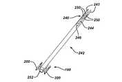
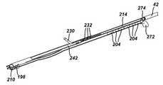
図14および図16において示されているように、組織回収機構260を、各切断工程に続いてリアルタイムで連続組織組立体190からサンプルを取り出すために、その組立体190の基端部に配置できる。この組織回収機構260は組織停止部分212(図23)のすぐ先端側においてサンプル・チューブ206に関連して位置決めできる。図21、図22および図23においてさらに詳細に示されているように、組織回収機構260は後退可能な外側スリーブ262を含む。この外側スリーブ262は、切断工程中にサンプル・チューブ206の内部を真空に保つために、O−リング263により気密に密封されている。切断工程の後に上記チューブ206から組織サンプルを取り出すためには、組織内孔部210の中の組織サンプルを露出させるために、外側スリーブ262がプル−タブ270により手動で回転されるかその位置が移動される。さらに、外側スリーブ262を後退させた後に、組織内孔部210の中の組織サンプルに接触するために、外側スリーブ262の下方の組織内孔部210の中に組織回収用のウインドウ264を形成できる。また、組織サンプル204における圧力の不均衡による、外側スリーブ262を後退させる時のそのサンプルの先端側への移動を防ぐために、上記ウインドウの中の組織サンプル204の先端側の面に対して空気圧を加えるために、空気の入口265をその組織回収ウインドウ264の先端側に配置できる。さらに、後退可能なスリーブ262における下方シリンダー266はそのスリーブを閉鎖または密封された位置に付勢するための戻しばね258を収容できる。このばね258の各端部はピン224により回収機構260にそれぞれ固定されている。また、この組織回収組立体260の基端部は、真空供給源36等からの、真空を組織内孔部210に供給するための真空連結部材268を含むことができる。また、真空連結ポート216を、真空供給源36等からの、真空を内孔部214に供給するために、回収機構260の中を通して延在するように、備えることも可能である。さらに、所与の処置の終了時において、組織回収組立体260は、以下においてさらに詳細に説明されているように、組織サンプルがサンプル・チューブ206から回収可能になるように、当該サンプル・チューブ206から分離できる。 As shown in FIGS. 14 and 16, a
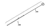
上記組織回収組立体260によるリアルタイムのサンプルの回収の代わりに、または、当該回収との組み合わせにおいて、組織サンプルは、サンプル・チューブ206をプローブ組立体32から分離して、組織回収組立体260を組織内孔部210の基端部から取り外すことにより、所与の処置の終了時に回収できる。また、上記サンプル・チューブ206を分離した後に、例えば、図24において示されているプランジャー様の部品278等のような、柔軟な棒材を含む、サンプル解放機構を組織内孔部210の一端部の中に挿入してその中を通して前進させることにより、図25において示されているように、その内孔部の反対側の端部からサンプルを取り出すことが可能である。あるいは、上記組織サンプル・チューブを、組織内孔部210の中において堆積されている組織サンプルに対する接近を可能にするために、所与の処置の終了時にその真空内孔部214が組織内孔部210から分離可能になるように、形成できる。 Instead of, or in combination with, the real-time sample collection by the
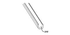
図26a乃至図26cは分離可能なサンプル貯蔵チューブに対応する一例の実施形態を示しており、この実施形態において、組織サンプルを露出させるために、剥がし等により、内孔部210の一部分が分離可能になるように、二重内孔部式のチューブ280が、参照番号または符号282により示されているような、組織内孔部210の外部に沿って弱められた側面部分を伴って押出成形されている。従って、反対方向の力が各内孔部210,214にそれぞれ加えられると、これら2つの内孔部は弱い部分282において剥がすことができ、図26bにおいて示されているように、組織内孔部210の上方の部分が真空内孔部214と共に分離する。この結果、残っている、組織内孔部210の下方の部分は、体積されている組織サンプルを収容している、開口したU字形の溝部を形成する(U字形の溝部が図26cにおいて示されている)。これらのサンプルは、鉗子またはその他の器具を用いて、開口された組織内孔部210から取り出すことができる。 FIGS. 26a-c show an example embodiment corresponding to a separable sample storage tube, in which a portion of the
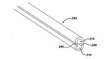
上記の弱められた側面部分282を伴うサンプル・チューブを押出成形する代替手段として、組織内孔部210および真空内孔部214は、図27aにおいて示されている一例の、二重内孔部式のチューブ284を形成するために、別々に押出成形してから組み合わせることが可能である。この実施形態において、真空内孔部214は、組織内孔部210が開口しているU字形の溝部を形成するように、当該組織内孔部210の上方の部分を含むように押出成形されている。これらの組織内孔部210および真空内孔部214は、接着剤またはその他の種類の固定用の機構により、上記U字形の溝部の上方のエッジ部分286に沿って結合されている。組織サンプルに接近するためには、図27bにおいて示されているように、上記の接着剤の結合またはその他の固定手段を破壊して真空内孔部214を組織内孔部210から剥がすために、反対方向の力がチューブ284に加えられる。これにより、サンプルは開口している組織内孔部から取り出すことができる。 As an alternative to extruding a sample tube with the weakened
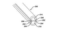
図28において示されている、分離可能なサンプル貯蔵チューブに対応するさらに別の実施形態において、二重内孔部式のチューブ290が別々に押出成形されている真空内孔部210および組織内孔部214を結合することにより形成されている。この実施形態において、真空内孔部214は少なくとも一対の外側に延出している歯部292を有する、閉じられている部材片として形成されている。一方、組織内孔部210は通路の内表面部に沿って対応している数の対の外側に延在しているノッチ部分294を有する、U字形の溝部として形成されている。上記歯部292は、上記サンプル・チューブを形成するために真空内孔部214および組織内孔部210を一緒に係止する機械的なラッチ部分296を形成するために、それぞれのノッチ部分294に係合するように形付けられている。これにより、真空内孔部214を組織内孔部210から反対の方向に引っ張ると、歯部292がノッチ部分294から分離して、組織サンプルを取り出すために組織内孔部の上部を開口できる。なお、上記の機械的なラッチ部分296は、上記の真空内孔部および組織内孔部を一緒に係止するために、接着剤またはその他の取付機構との組み合わせにおいて使用可能である。 In yet another embodiment corresponding to the separable sample storage tube shown in FIG. 28, a
図29および図30は、上記サンプル貯蔵チューブ206が図26乃至図28において示されている分離可能なサンプル貯蔵チューブにより置き換えられている、連続組織貯蔵組立体190に対応する代替的な実施形態を示している。加えて、上記組織回収機構260が組織内孔部ピール・タブ272により置き換えられている。さらに、組織停止部分が組織内孔部210の基端部において内孔部ピール・タブ272の中に配置されている。また、チューブ・コネクタ274が真空内孔部214の基端部を、真空供給源36に連通している真空配管42等のような、軸方向の真空配管に接続している。このような実施形態において、組織サンプルは組織停止部分から先端側に堆積される。これらの組織サンプル204は組織内孔部を真空内孔部214から剥がすことによりリアルタイムで取り出すことができる。あるいは、これらの組織サンプルは所与の処置の終了時に取り出すことも可能である。 FIGS. 29 and 30 show an alternative embodiment corresponding to a continuous
図31a乃至図31dは生検処置における最初の2回の切断工程に対応する下方コネクタ198、組織内孔部210および棒材230のそれぞれの前進および後退した位置を示している。図31aにおいて示されているように、カッター100が完全に先端側の位置に、すなわち、組織受容ポート86の中を通して完全に、前進すると、組織内孔部210も完全に先端側に前進し、この組織内孔部は外側スリーブ228に対して実質的に平行な状態になる。その後、カッター100が組織の切断に続いて組織受容ポート86から後退すると、組織内孔部210は、図31bにおいて示されているように、所与の基端側の位置まで駆動キャリジ134と共に後退する。この位置において、組織内孔部210の先端側の所与の長さの部分が外側スリーブ228から、曲がっている等の状態で、下方に延出している。また、往復動式の部材242も後退して棒材230における次の組のラチェット歯部232を把持している。その後、図31cにおいて示されている、次の切断工程において、カッター100は再び駆動キャリジ134により完全に前進して、下方コネクタ198が再び組織内孔部210を先端側に引っ張る。さらに、この下方コネクタ198が先端側に引っ張られると、係合用のつめ250が棒材230のラチェット歯部232を引っ張って、その棒材を真空内孔部214の中を通して開口部234から外に前進させる。この2回目の切断工程の終了時に、図31dにおいて示されているように、組織内孔部210は再び基端側に後退する。 FIGS. 31a-31d show the advanced and retracted positions of the
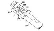
図32は組織貯蔵組立体52に対応する代替的な実施形態を示しており、この実施形態において、上記貯蔵組立体は並列式の組織堆積組立体300を含んでいる。この並列式の組織堆積組立体300において、組織サンプルは組織貯蔵部品の中に1個ずつ横並びに貯蔵されて、その処置の終了時に取り出される。図32および図33において示されているように、上記並列式の堆積組立体300は一連の横並びの内孔部304を含む組織貯蔵部品302を有している。上記内孔部304のそれぞれは、組織受容ポート86から吸引される組織サンプルを貯蔵するために、その組織受容ポート86の長さよりもわずかに長い。また、上記部品302は、内部に貯蔵されている組織サンプルの視覚的な検査を可能にするために、透明なプラスチック材料により構成できる。さらに、組織サンプルが各組織内孔部304の中を完全に通過して真空システム36の中に移動することを防ぎながら、真空をその内孔部に伝達されるように供給するために、一体化されているノック−アウト・ピン306(図34)を、それぞれの組織内孔部304の基端部に備えることができる(例えば、それぞれのノックアウト・ピン306は、内孔部304に真空を供給するための伝達を行なう程度に十分に大きいが、組織サンプルがその内孔部304の先端部から通過して出ることを可能にしない程度に十分に小さい、小さな中心開口部を含むことができる)。 FIG. 32 shows an alternative embodiment corresponding to the
図32および図33にもどり、内部に組織内孔部310を有している、組織チューブ308が、プローブ32の中のチューブ152に接続するために、上記部品302の先端側に延在している。これらのチューブ152および308は、カッター100の内孔部104から部品302の中の内孔部304に到る連続的で、概ね直線状の通路を形成するために、整合できる。図35において示されている、O−リングのシール部材312を、組織内孔部310とチューブ308に対して整合されている内孔部304との間の通路を密封するために、組織チューブ308の基端部に備えることができる。上記のサンプル・チューブ152および組織チューブ308は、例えば、図15aおよび図15bにおいて示されている部材に類似しているスナップ・ファスナー等のような、任意の適当な種類の固定機構により着脱自在に接続できる。第1の真空ポート314は、チューブ308に整合している内孔部304を通して真空を組織内孔部310に供給するために、上記部品302の基端側に配置できる。また、第2の外側の真空ポート316は部品302の先端側の位置における組織内孔部310に真空を供給するために使用できる。さらに、これらの真空ポート314,316のそれぞれは、組織をカッター100の内孔部104の中に基端側に引き込むための真空を供給するために、軸方向の真空配管42の中を介して真空供給源36に取り付けることができる。また、外側の真空ポート316は組織チューブ308を囲む真空チャンバー320に取り付けることができる。この組織チューブ308は、真空チャンバー320とチューブ内孔部310との間に真空を伝達するために、真空チャンバー320の中において複数の離間している穴を含むことができる。これらの外側真空ポート316およびチャンバー320は(組織サンプルがサンプリング中に多数の断片にばらばらになる場合等において)組織サンプルの基端側の移動を補助するために付加的な真空を供給する。 Returning to FIGS. 32 and 33, a
組織サンプルが内孔部304の中に貯蔵された後に、上記部品302を、組織内孔部310に対して次の隣接している内孔部を軸方向に整合するように、横方向に移動することができる。図33において示されているように、カム部材322が部品302を移動するために備えられている。このカム部材322は部品302の下方に延在しているハウジング324の中に配置されている。このカム部材322は、それぞれの切断工程中に駆動キャリジ134と共に先端側および基端側に移動するように、プローブ組立体32の中においてその駆動キャリジ134に操作可能に接続している。このカム部材322はエンド・キャップ330の中を通して先端側に延在している機械的なケーブル326により駆動キャリジ134に取り付けられている。このケーブル326は駆動キャリジ134に取り付けられていて、この駆動キャリジ134が先端側に移動すると、カム部材322を先端側に引っ張る。さらに、カム部材322が移動すると、このカム部材におけるカム面332が部品302の下面部におけるボス334(図34において示されている)に対して相互作用して、部品302を移動する。このカム面332はボス334により偏向する材料の傾斜した柔軟な切片を含むことができる。図36aにおいて示されているように、上記カム面332は、カム部材322が切断工程の前の最も基端側の位置にある時に、仮想図のボス336,338により示されている、2個のボスの間の偏向されていない位置にある。その後、このカム部材322が切断工程の開始時に先端側に前進すると、カム面332はボス336とそのカム面の第1の面との間の接触により偏向してその位置をずらす。さらに、カム部材322が先端側に前進し続けると、図36bにおいて示されているように、上記ボス336がカム面と停止ブロック340との間に形成される開口部を通過する位置まで、カム面332を偏向する。このボス336が上記の偏向しているカム面により形成された開口部を通過した後に、このカム面は、停止ブロック340に接触している所与の偏向されていない位置まで、ばねの力により戻る。 After the tissue sample has been stored in the
その後、駆動キャリジ134が組織の切断に続いて後退し始めると、ハウジング324の先端部の中における戻しばね224がカム部材322をそのハウジングの中において基端側に押す。これにより、カム部材322は基端側に後退し、上記カム面332の反対側の面がボス336に接触する。さらに、カム部材322が後退し続けると、図36cにおいて示されているように、そのカム面332における角度により、ボス336が横方向に押される。このようにして、ボス336が横方向に押されると、部品302は組織チューブ308に対して横方向に移動し、これにより、次の隣接している内孔部304がチューブ308を通して次の組織サンプルを受容するように位置決めできる。図32および図33において示されているように、部品302はカム部材のハウジング324とデテント・アーム342との間に配置されている。このデテント・アーム342は部品302の上面部を横切って先端側に延在している。この部品302がカム面332およびボス336の相互作用により横方向に移動すると、デテント・アーム342は一連の移動用のデテント344に係合する。この移動用のデテント344は、それぞれの移動動作に続いて、次の作動中の内孔部304を内孔部310に対して整合状態に係止する。上記複数のボス334および移動用のデテント344は部品302が生検処置の間に複数の組織サンプルを貯蔵するために繰り返して移動されることを可能にする。その後、生検処置の終了時において、部品302はハウジング324とデテント・アーム342との間から取り外すことが可能になり、組織サンプルは個々の組織内孔部304から取り出すことができる。この場合に、上記部品302の上面部は、それぞれのサンプルが内孔部304から容易に取り出されることを可能にするために、カバーまたはその他の取り外し可能な部分を含むことができる。 Thereafter, when
図37はホルスター34に対応する例示的な駆動組立体350の分解等角図である。この図37において示されている組立体において、上記の移動および回転の駆動系列(カッター100の回転および移動を行なうための駆動系列)は、ホルスター34と、制御モジュール46の中のモーター等のような、遠隔位置に配置されているモーターとの間に延在している、単一の回転可能なケーブル55(図1においても示されている)によりそれぞれ駆動される。すなわち、単一の駆動ケーブルでも、本発明の短縮されたカッター・ストロークのために、両方の駆動系列を回転することが可能である。つまり、上記の短縮されたカッター・ストロークはハンドピース30の寸法、ならびに駆動モーターにおける負荷、を以前の生検装置に対して減少することを可能にしている。また、単一の回転可能なケーブルを介してハンドピース30に電力供給することは、強磁性のモーター部品がそのハンドピースから分離されているので、そのハンドピースをMRI案内型の処置において利用することを可能にしている。また、このハンドピースはマンモグラフィおよび超音波による案内型の処置においても使用可能である。従って、共通のプローブ組立体およびハンドピースを多数の画像化環境に対応して利用できる。例えば、MRI案内型の処置において、上記の回転可能なケーブルの長さはMRIのボアの近くまたはその中における使用に適合するように増加できる。 FIG. 37 is an exploded isometric view of an
図37において示されている実施形態において、回転可能なケーブル55がホルスター34に対して回転駆動を行なうための駆動ケーブル入力連結部材352に取り付けられている。さらに、この入力連結部材352からの駆動軸部354が基端側のハウジング356まで延在している。この基端側ハウジング356の中において、入力歯車360が、移動駆動軸部364および回転駆動軸部366におけるそれぞれの対応する歯車に係合するように、スペーサー362とベアリング389との間の入力駆動軸部354に取り付けられている。この入力歯車360の、移動軸部の歯車370および回転軸部の歯車372との相互作用は移動および回転の駆動軸部364,366に対して回転の駆動力をそれぞれ伝達する。これらの移動および回転の駆動軸部364,366は基端側ハウジング356から中央のハウジング374の中の一対のボアの中を通して延在している。この場合に、移動および回転の各歯車370,372はそれぞれのベアリング376により基端側および中央の各ハウジングの間において離間している。 In the embodiment shown in FIG. 37, a
上記中央ハウジング374の先端側において、ホルスター34は各駆動軸部の回転に関するフィードバック信号を制御モジュール46に供給するためのロータリー・エンコーダー380を含んでいる。このエンコーダー380は移動または回転の駆動軸のいずれかに取り付けることが可能である。また、ホルスター34は移動駆動軸部364の上に随意的な衛星歯車箱382も含んでいる。この歯車箱382は、駆動キャリジ134の移動およびカッター104の回転に対応するそれぞれの変化している速度を生じるために、上記の移動および回転の駆動系列の間の歯車の減速を行なう。これらの歯車箱382およびエンコーダー380の先端側において、駆動組立体350はハウジング384を含んでいる。このハウジング384は、上記の移動駆動系列を移動駆動入力軸部386に連結し、回転駆動系列を回転駆動入力軸部388に連結するための、それぞれの接続部分を含む。これらの駆動入力軸部386,388のそれぞれは、上記プローブ組立体32の中において対応している各駆動軸部におけるスロットに操作可能に係合するように、形付けられている先端部を有している。特に、移動駆動入力軸部386は移動軸部142(図4において示されている)のスロット128に係合するように形付けられており、回転駆動入力軸部388は回転駆動軸部114のスロット132に係合するように形付けられている。なお、図6について上述されているように、上記駆動入力軸部は、各軸部の間の連結用の長さを減少するために、図4および図37において示されている係合用のスロットおよび先端部分の代わりに、成形されたインターフェイス部分を有することも可能である。このようにして、移動および回転の各駆動軸部386,388は、プローブ組立体32およびホルスター34が接続される時に、駆動および移動の各軸部114,142に係合するためにハウジング384から先端側に延出する。 On the distal end side of the
図37において示されている実施形態は移動および回転の各軸部を操作可能に駆動するための単一の駆動ケーブルの入力を含む。また、別の実施形態において、上記ホルスター34の中に取り付けられている単一のモーターが上記の回転可能なケーブル55に換わることができる。すなわち、この単一のモーターは適当な歯車式の組立体を介して上記の移動および回転の各軸部の両方を駆動する。このモーターは上記駆動組立体の上方または基端側に取り付けることができる。さらに、別の実施形態は上記単一のモーターを2個のモーターに換えている。この場合に、1個のモーターは上記の移動駆動入力軸部を駆動し、別のモーターは回転駆動入力軸部を駆動することになる。 The embodiment shown in FIG. 37 includes a single drive cable input for operably driving the translation and rotation shafts. In another embodiment, a single motor mounted in the
上記の説明されている実施形態において、上記のカッター100に対応する切断ストロークの長さは組織受容ポート86の長さよりもわずかに長い程度まで減少されている。このストロークの減少は、組織サンプルが、カッターを後退させることにより針の中を通して基端側に引っ張られるのではなく、カッター内孔部の中を通して吸引されることにより、部分的に可能になる。さらに、このような切断ストロークの長さの減少は多数の利点を有している。この減少された切断ストロークの長さの利点の一つは、プローブ組立体の全体の大きさおよび重量が減少可能になり、これにより、その生検装置がこれまでに寸法が一つの制約であった種々の画像化の環境において用いられることが可能になる、と言うことである。特に、プローブ組立体の減少された大きさは、わずかな調節により、本質的に共通のプローブ組立体が開口型および閉鎖型の両方のボアのMRI案内型の処置、ならびにマンモグラフィおよび超音波方式の処置において用いられることを可能にする。また、共通のケーブル駆動型のホルスターを、マンモグラフィおよび超音波の両方による案内型の処置において使用可能な単一または2個のモーターの実施形態のいずれかと共に、種々の画像化様式のそれぞれにおいて使用することも可能である。加えて、共通の制御モジュールが、上記3種類の画像化環境のいずれにおいても、ハンドピースを制御するために使用できる。また、上記のプローブ組立体は、画像の人為的構造を減少するために、プラスチックまたはセラミック等のような、非強磁性材料により構成されている針およびカッターのサブアセンブリーを利用することによりMRI案内型の処置において使用するために適合できる。加えて、上記のカッター組立体は、切断工程の開始前のMRI画像化のために、図7および図8に関連して上述されているように、プローブから取り外すことが可能である。あるいは、上記カッターの先端部は、画像化の間に、組織受容ポートの領域から簡単に基端側に後退できる。 In the described embodiment, the length of the cutting stroke corresponding to the
上記の異なる画像化様式のそれぞれに適合するために、それぞれの画像化環境に対して特異的な、再使用可能なハンドピースの基部ユニットが利用できる。これらのハンドピースの基部ユニットのそれぞれは、オペレーターの要求および特定の画像化環境の制約に応じて、上記の針孔を前進および/または回転するために使用できる。また、上記基部ユニットのそれぞれは、同一のプローブが種々の画像化の様式の間で用いられることを可能にすることに、そのプローブ組立体を適合させるように設計されている。 In order to adapt to each of the above different imaging modalities, a reusable handpiece base unit specific to the respective imaging environment is available. Each of these handpiece base units can be used to advance and / or rotate the needle holes as required by the operator and the constraints of the particular imaging environment. Each of the base units is also designed to adapt its probe assembly to allow the same probe to be used between various imaging modes.
図38aはマンモグラフィ案内型の処置においてプローブ組立体32と共に使用するための基部420を示している。この基部420は取付部分422によりマンモグラフィ装置の定位(stereotactic)アームに取り付けることができる。凹状の嵌め合わせ領域424が、プローブの下方外殻部分に適合するために、基部420の中に設けられている。すなわち、プローブ組立体32は所与の処置の開始の前に上記嵌め合わせ領域424の中に留まることができる。さらに、発射用または前進用のボタン426が、関連の組織の塊りの中にプローブ組立体の針を前進させるために、基部420の中に含まれている。また、この基部ユニット420の側面におけるノブ430が当該ユニットの中の前進用のばねを圧縮している。これにより、上記ボタン426が押圧されると、上記のばねがプローブ組立体32を押してプローブ組立体および嵌め合わせ領域424の全体を取付部分422に対して前方に強制的に駆動する。 FIG. 38a shows a
孔回転用の歯車432もまた、針が組織の塊りの中に配置された後にプローブ組立体の組織受容ポートを回転するために、基部420の凹状の領域の中に備えられている。この孔回転歯車432は複数の歯車の歯434を含む。これらの歯車の歯434は、プローブ組立体32の中の針支持部品に対して一体の第2の歯車における類似の形状の歯に係合するために、上記凹状の表面の領域から部分的に突出している。この第2の針の歯車における歯はプローブ外殻部分の中に引っ込んでいるが、プローブが嵌め合わせ領域424の中に留まっている時に、孔回転歯車432により接近可能である。また、ノブ436が手動回転式の歯車432のために基部420の基端部に備えられている。歯車432が回転すると、これらの歯車の間の係合が針を回転させ、これにより、組織受容ポートが組織の塊りの中において再位置決めされる。プローブ組立体32は、針の歯車を係止してその歯車が嵌め合わせ領域424の外側で回転することを防ぐ柔軟な係合用のフィンガー部分を含む。この場合に、プローブ組立体32が嵌め合わせ領域424の中に挿入されると、この柔軟なフィンガー部分が、針の歯車から離脱して、その歯車を基部の歯車432の回転に応じて回転可能にするように、偏向される。図38bは嵌め合わせ領域424の中に留められているプローブ組立体32を示している。 A
図39は超音波による画像化環境の中において使用するための類似の種類のプローブの基部を示している。図39において示されているように、この基部ユニット440はプローブ組立体32の下方外殻部分に適合するための嵌め合わせ領域442を含む。また、ノブ444が基部440の中の前進用のばねを押圧するために備えられていて、ボタン446が、組織の塊りの中にプローブ組立体および嵌め合わせ領域424を「発射または前進させる(fire)」ように、上記ばねを解放するために備えられている。この場合に、超音波の環境の中において、基部440は手持型であって、オペレーターにより必要に応じて操作することが可能である。従って、オペレーターが上記基部および/またはプローブ組立体を手動で回転することにより針を回転できるので、針の回転機構はこの基部440において必要でない。 FIG. 39 shows the base of a similar type of probe for use in an ultrasound imaging environment. As shown in FIG. 39, the
図40において示されているように、第3の種類のプローブ基部450がMRI案内型の処置において使用するために提供されている。この基部450はMRIユニットの中の位置確認用のユニットに取り付けることができる。本発明におけるプローブ組立体の減少された大きさは、そのプローブにより生じる減少された片持ち梁状の負荷により、上記位置確認用のユニットに対する構造上の要求を減らしている。この場合に、MRIの基部450は、下方プローブ外殻部分に適合するための凹状の嵌め合わせ領域452を、含んでいる。加えて、この基部は、プローブの下方外殻部分から延出している類似の形状の歯に係合する複数の歯車の歯を有する孔回転用の歯車454を含む。下方のプローブ外殻部分の中の歯車は、図38において示されているマンモグラフィ用の嵌め合わせ領域の実施形態に類似している様式で歯車454が回転するたびに、針を回転するためにその針に取り付けられている。さらに、孔回転用のノブ456が、歯車454、およびこれに追随して、針の中の組織受容用の孔を、手動で回転するために、上記基部450の基端部に配置されている。この基部450は組織の中に針を位置決めするための前進機構を必要としない。しかしながら、プローブ組立体がMRIユニットの中においてさらに容易に適合することを可能にするために、そのプローブ組立体と共に複数の針の長さを使用できる。この場合に、選択される特定の針の長さは患者の体の中の関連の組織の塊りの深さに応じて決まる。 As shown in FIG. 40, a third type of probe base 450 is provided for use in an MRI guided procedure. The base 450 can be attached to a position confirmation unit in the MRI unit. The reduced size of the probe assembly in the present invention reduces the structural requirements for the location unit due to the reduced cantilevered load produced by the probe. In this case, the MRI base 450 includes a concave mating region 452 to fit the lower probe shell portion. In addition, the base includes a hole rotating gear 454 having a plurality of gear teeth that engage similar shaped teeth extending from the lower shell portion of the probe. The gear in the lower probe shell portion rotates its needle to rotate the needle each time the gear 454 rotates in a manner similar to the mammographic mating region embodiment shown in FIG. Attached to the needle. In addition, a hole rotation knob 456 is disposed at the proximal end of the base 450 for manually rotating the gear 454 and the tissue receiving hole in the needle following it. . This base 450 does not require an advancement mechanism for positioning the needle in the tissue. However, multiple needle lengths can be used with the probe assembly to allow the probe assembly to fit more easily within the MRI unit. In this case, the length of the particular needle selected will depend on the depth of the associated tissue mass in the patient's body.
上記MRIの基部450の使用に対する代替例として、図41において示されているような、MRI位置確認用の深さゲージ460がプローブ組立体を位置決めするために使用できる。この実施形態において、深さ停止部分462がプローブ組立体および/または針80に取り付けられている。さらに、この深さ停止部分はプローブの針の所望の深さを調節するための調節ノブ464を含む。この針が適当に位置決めされた後に、上記の停止部分に到達するまで、プローブが患者の組織の中に挿入される。その後、その患者はMRI装置の中に配置されて、プローブ組立体のための付加的な支持を伴わずに画像化されることができる。さらに、上記組織の中の針の位置が確認された後に、組織サンプリングを始めるために、ホルスターがプローブ組立体に取り付けられる。 As an alternative to the use of the MRI base 450, an MRI
以上において、本発明の好ましい実施形態が図示および本明細書において説明されているが、これらの実施形態が例示のみの目的のために示されていることが、当業者において明らかになるであろう。また、多数の変形、変化、および置換が、添付の特許請求の範囲の各項の趣旨および範囲から逸脱することなく、当業者において想到されるようになるであろう。加えて、本発明に関連して説明されているそれぞれの要素はその要素の機能を果たすための所与の手段として代わりに説明することができる。 While preferred embodiments of the present invention have been illustrated and described herein, it will be apparent to those skilled in the art that these embodiments are shown for illustrative purposes only. . Numerous variations, changes, and substitutions will occur to those skilled in the art without departing from the spirit and scope of each appended claim. In addition, each element described in connection with the present invention may alternatively be described as a given means for performing the function of that element.
〔実施の態様〕
(1)生検装置であって、
カニューレと、
前記カニューレの中に引き込まれている組織を切断するために、そのカニューレに対して移動可能な、カッターと、
組織サンプルを保持するためのサンプル内孔部を有する組織貯蔵組立体であって、前記サンプル内孔部が複数の流体開口部に連通している、組織貯蔵組立体と、
前記流体開口部を連続的に露出させるための、移動可能な部材と、
を備えている、生検装置。
(2)実施態様1に記載の生検装置であって、
前記サンプル内孔部が端面を重ね合わせる構成で前記組織サンプルを保持するように構成されている、生検装置。
(3)実施態様1に記載の生検装置であって、
前記移動可能な部材の移動が前記カッターの移動に対して操作可能に付随している、生検装置。
(4)実施態様3に記載の生検装置であって、
前記カニューレが、所与の長手方向の長さを有する組織受容ポートを含む、生検装置。
(5)実施態様4に記載の生検装置であって、
前記移動可能な部材が、切断されたそれぞれの組織サンプルに対応して、少なくともほぼ前記組織受容ポートの長手方向の長さだけ、移動することに適合している、生検装置。Embodiment
(1) A biopsy device,
A cannula,
A cutter movable relative to the cannula to cut tissue drawn into the cannula;
A tissue storage assembly having a sample bore for holding a tissue sample, wherein the sample bore communicates with a plurality of fluid openings;
A movable member for continuously exposing the fluid opening;
A biopsy device.
(2) The biopsy device according to Embodiment 1,
A biopsy device configured to hold the tissue sample in a configuration in which the sample inner holes overlap end surfaces.
(3) The biopsy device according to Embodiment 1,
A biopsy device, wherein movement of the movable member is operatively associated with movement of the cutter.
(4) The biopsy device according to embodiment 3,
A biopsy device, wherein the cannula includes a tissue receiving port having a given longitudinal length.
(5) The biopsy device according to embodiment 4,
A biopsy device, wherein the movable member is adapted to move at least approximately the longitudinal length of the tissue receiving port corresponding to each cut tissue sample.
(6)生検装置であって、
組織受容ポートを有する、カニューレと、
前記組織受容ポートの中に受容されている組織から組織サンプルを切断するために前記カニューレに対して移動するように配置されている、中空のカッターと、
端面を重ね合わせる構成で切断された組織サンプルを保持するために前記組織受容ポートの基端側に配置されている、組織貯蔵組立体と、
前記組織受容ポートの中に引き込まれている組織から切断されたサンプルを前記組織貯蔵組立体まで移送するための流体の圧力差を供給するための装置と、
を備えている、生検装置。
(7)実施態様6に記載の生検装置であって、
前記組織貯蔵組立体が前記生検装置から分離可能である、生検装置。
(8)実施態様6に記載の生検装置であって、
前記組織貯蔵組立体が、前記組織サンプルを見ることを可能にするための少なくとも1つの透明な部分を含む、生検装置。
(9)実施態様6に記載の生検装置であって、
前記組織貯蔵組立体が、サンプル内孔部を有する組織サンプル・チューブを含み、当該組織サンプル・チューブの少なくとも一部分が前記サンプル内孔部の中に配置されているサンプルを露出させるように構成可能である、生検装置。
(10)実施態様9に記載の生検装置であって、
前記サンプル・チューブの少なくとも一部分が、前記サンプル内孔部の中に配置されているサンプルを露出させるために、そのサンプル・チューブの長さの少なくとも一部分に沿って解放可能である、生検装置。(6) a biopsy device,
A cannula having a tissue receiving port;
A hollow cutter arranged to move relative to the cannula to cut a tissue sample from tissue received in the tissue receiving port;
A tissue storage assembly disposed proximal to the tissue receiving port to hold a tissue sample cut in an end-to-end configuration;
A device for providing a fluid pressure differential for transferring a sample cut from tissue drawn into the tissue receiving port to the tissue storage assembly;
A biopsy device.
(7) The biopsy device according to Embodiment 6,
A biopsy device, wherein the tissue storage assembly is separable from the biopsy device.
(8) The biopsy device according to embodiment 6,
A biopsy device, wherein the tissue storage assembly includes at least one transparent portion to allow viewing of the tissue sample.
(9) The biopsy device according to embodiment 6,
The tissue storage assembly includes a tissue sample tube having a sample bore, and at least a portion of the tissue sample tube is configurable to expose a sample disposed in the sample bore. There is a biopsy device.
(10) The biopsy device according to embodiment 9,
A biopsy device, wherein at least a portion of the sample tube is releasable along at least a portion of the length of the sample tube to expose a sample disposed within the sample bore.
(11)実施態様9に記載の生検装置であって、
前記サンプル・チューブの一部分が、前記サンプル内孔部の中に配置されているサンプルの取り出しを可能にするために、そのサンプル・チューブの長さの少なくとも一部分に沿って剥離可能である、生検装置。
(12)実施態様6に記載の生検装置であって、
前記組織貯蔵組立体が、組織サンプルを保持するためのサンプル内孔部を有するサンプル・チューブを含む、生検装置。
(13)実施態様12に記載の生検装置であって、
前記サンプル・チューブが、少なくとも2つの概ね平行な内孔部を含む、生検装置。
(14)実施態様13に記載の生検装置であって、
前記少なくとも2つの概ね平行な内孔部の間において流体の連通を行なうための、複数の流体の通路を備えている、生検装置。
(15)実施態様12に記載の生検装置であって、
前記サンプル内孔部からサンプルを押し動かすために、そのサンプル内孔部の中に挿入可能な棒材をさらに備えている、生検装置。(11) The biopsy device according to embodiment 9,
A biopsy in which a portion of the sample tube is peelable along at least a portion of the length of the sample tube to allow removal of a sample disposed in the sample bore apparatus.
(12) The biopsy device according to Embodiment 6,
A biopsy device, wherein the tissue storage assembly includes a sample tube having a sample bore for holding a tissue sample.
(13) The biopsy device according to embodiment 12,
A biopsy device, wherein the sample tube includes at least two generally parallel bores.
(14) The biopsy device according to embodiment 13,
A biopsy device comprising a plurality of fluid passages for fluid communication between the at least two generally parallel bores.
(15) The biopsy device according to embodiment 12,
A biopsy device further comprising a rod that can be inserted into the sample bore to push the sample from the sample bore.
(16)生検装置であって、
組織受容ポートを有する、カニューレと、
前記組織受容ポートの中に引き込まれている組織を切断するために前記カニューレに対して移動するように配置されている、中空のカッターと、
端面を重ね合わせる構成で、組織サンプルを保持するための、組織貯蔵組立体と、を備えており、
前記組織貯蔵組立体の中に貯蔵されているそれぞれの組織サンプルが、追加の組織サンプルを切断する前に、検査のために取り外し可能である、生検装置。
(17)生検方法であって、
組織受容ポートを有する中空のカニューレを供給する工程と、
前記カニューレに対して移動可能な中空のカッターを供給する工程と、
組織の塊りの中に上記組織受容ポートを位置決めする工程と、
前記カニューレの組織ポートの中に組織を受容する工程と、
前記組織ポートに対して前記中空のカッターを移動させる工程と、
前記中空のカッターの先端部により組織サンプルを切断する工程と、
前記中空のカッターの基端部の中を通して切断された組織サンプルを移送する工程と、
前記切断された組織サンプルを端面を重ね合わせる構成で貯蔵する工程と、を含む、生検方法。
(18)実施態様17に記載の方法であって、
前記組織サンプルを貯蔵する工程が、サンプル内孔部の中に組織サンプルを貯蔵する処理、を含む、方法。
(19)実施態様18に記載の方法であって、
前記サンプル内孔部の中にサンプルを貯蔵する処理に伴って、そのサンプル内孔部に付随している1つ以上の流体の通路を露出させる工程をさらに含む、方法。
(20)実施態様19に記載の方法であって、
前記サンプル内孔部に付随している1つ以上の流体通路を露出させる工程が前記カッターの移動に操作可能に付随している、方法。(16) A biopsy device,
A cannula having a tissue receiving port;
A hollow cutter arranged to move relative to the cannula to cut tissue drawn into the tissue receiving port;
A tissue storage assembly for holding a tissue sample in a configuration in which the end faces are superimposed,
A biopsy device wherein each tissue sample stored in the tissue storage assembly is removable for examination prior to cutting additional tissue samples.
(17) A biopsy method,
Providing a hollow cannula having a tissue receiving port;
Providing a hollow cutter movable relative to the cannula;
Positioning the tissue receiving port in a tissue mass;
Receiving tissue in the tissue port of the cannula;
Moving the hollow cutter relative to the tissue port;
Cutting the tissue sample with the tip of the hollow cutter;
Transferring the cut tissue sample through the proximal end of the hollow cutter;
Storing the cut tissue sample in a configuration in which end faces are overlaid.
(18) The method according to
Storing the tissue sample comprises storing the tissue sample in a sample bore.
(19) The method according to embodiment 18,
The method further comprises exposing one or more fluid passages associated with the sample bore in connection with storing the sample in the sample bore.
(20) The method according to embodiment 19,
A method wherein the step of exposing one or more fluid passages associated with the sample bore is operatively associated with movement of the cutter.
Claims (13)
Translated fromJapaneseカニューレと、
前記カニューレの中に引き込まれている組織を切断するために、そのカニューレに対して移動可能な、カッターと、
組織サンプルを保持するためのサンプル内孔部を有する組織貯蔵組立体であって、前記サンプル内孔部が複数の流体開口部に連通している、組織貯蔵組立体と、
前記流体開口部を連続的に露出させるための、移動可能な部材と、
を備えている、生検装置。A biopsy device,
A cannula,
A cutter movable relative to the cannula to cut tissue drawn into the cannula;
A tissue storage assembly having a sample bore for holding a tissue sample, wherein the sample bore communicates with a plurality of fluid openings;
A movable member for continuously exposing the fluid opening;
A biopsy device.
組織受容ポートを有する、カニューレと、
前記組織受容ポートの中に受容されている組織から組織サンプルを切断するために前記カニューレに対して移動するように配置されている、中空のカッターと、
端面を重ね合わせる構成で切断された組織サンプルを保持するために前記組織受容ポートの基端側に配置されている、組織貯蔵組立体と、
前記組織受容ポートの中に引き込まれている組織から切断されたサンプルを前記組織貯蔵組立体まで移送するための流体の圧力差を供給するための装置と、
を備えている、生検装置。A biopsy device,
A cannula having a tissue receiving port;
A hollow cutter arranged to move relative to the cannula to cut a tissue sample from tissue received in the tissue receiving port;
A tissue storage assembly disposed proximal to the tissue receiving port to hold a tissue sample cut in an end-to-end configuration;
A device for providing a fluid pressure differential for transferring a sample cut from tissue drawn into the tissue receiving port to the tissue storage assembly;
A biopsy device.
前記組織貯蔵組立体が前記生検装置から分離可能である、生検装置。A biopsy device according to claim 2,
A biopsy device, wherein the tissue storage assembly is separable from the biopsy device.
前記組織貯蔵組立体が、前記組織サンプルを見ることを可能にするための少なくとも1つの透明な部分を含む、生検装置。A biopsy device according to claim 2,
A biopsy device, wherein the tissue storage assembly includes at least one transparent portion to allow viewing of the tissue sample.
前記組織貯蔵組立体が、サンプル内孔部を有する組織サンプル・チューブを含み、当該組織サンプル・チューブの少なくとも一部分が前記サンプル内孔部の中に配置されているサンプルを露出させるように構成可能である、生検装置。A biopsy device according to claim 2,
The tissue storage assembly includes a tissue sample tube having a sample bore, and at least a portion of the tissue sample tube is configurable to expose a sample disposed in the sample bore. There is a biopsy device.
前記サンプル・チューブの少なくとも一部分が、前記サンプル内孔部の中に配置されているサンプルを露出させるために、そのサンプル・チューブの長さの少なくとも一部分に沿って解放可能である、生検装置。The biopsy device according to claim 5,
A biopsy device, wherein at least a portion of the sample tube is releasable along at least a portion of the length of the sample tube to expose a sample disposed within the sample bore.
前記サンプル・チューブの一部分が、前記サンプル内孔部の中に配置されているサンプルの取り出しを可能にするために、そのサンプル・チューブの長さの少なくとも一部分に沿って剥離可能である、生検装置。The biopsy device according to claim 5,
A biopsy in which a portion of the sample tube is peelable along at least a portion of the length of the sample tube to allow removal of a sample disposed in the sample bore apparatus.
前記組織貯蔵組立体が、組織サンプルを保持するためのサンプル内孔部を有するサンプル・チューブを含む、生検装置。A biopsy device according to claim 2,
A biopsy device, wherein the tissue storage assembly includes a sample tube having a sample bore for holding a tissue sample.
前記サンプル・チューブが、少なくとも2つの概ね平行な内孔部を含む、生検装置。A biopsy device according to claim 8,
A biopsy device, wherein the sample tube includes at least two generally parallel bores.
前記少なくとも2つの概ね平行な内孔部の間において流体の連通を行なうための、複数の流体の通路を備えている、生検装置。The biopsy device according to claim 9, wherein
A biopsy device comprising a plurality of fluid passages for fluid communication between the at least two generally parallel bores.
前記サンプル内孔部からサンプルを押し動かすために、そのサンプル内孔部の中に挿入可能な棒材をさらに備えている、生検装置。A biopsy device according to claim 8,
A biopsy device further comprising a rod that can be inserted into the sample bore to push the sample from the sample bore.
組織受容ポートを有する、カニューレと、
前記組織受容ポートの中に引き込まれている組織を切断するために前記カニューレに対して移動するように配置されている、中空のカッターと、
端面を重ね合わせる構成で、組織サンプルを保持するための、組織貯蔵組立体と、
を備えており、
前記組織貯蔵組立体の中に貯蔵されているそれぞれの組織サンプルが、追加の組織サンプルを切断する前に、検査のために取り外し可能である、生検装置。A biopsy device,
A cannula having a tissue receiving port;
A hollow cutter arranged to move relative to the cannula to cut tissue drawn into the tissue receiving port;
A tissue storage assembly for holding a tissue sample in an end-to-end configuration;
With
A biopsy device wherein each tissue sample stored in the tissue storage assembly is removable for examination prior to cutting additional tissue samples.
組織受容ポートを有する中空のカニューレを供給する工程と、
前記カニューレに対して移動可能な中空のカッターを供給する工程と、
組織の塊りの中に上記組織受容ポートを位置決めする工程と、
前記カニューレの組織ポートの中に組織を受容する工程と、
前記組織ポートに対して前記中空のカッターを移動させる工程と、
前記中空のカッターの先端部により組織サンプルを切断する工程と、
前記中空のカッターの基端部の中を通して切断された組織サンプルを移送する工程と、
前記切断された組織サンプルを端面を重ね合わせる構成で貯蔵する工程と、
を含む、生検方法。
A biopsy method,
Providing a hollow cannula having a tissue receiving port;
Providing a hollow cutter movable relative to the cannula;
Positioning the tissue receiving port in a tissue mass;
Receiving tissue in the tissue port of the cannula;
Moving the hollow cutter relative to the tissue port;
Cutting the tissue sample with the tip of the hollow cutter;
Transferring the cut tissue sample through the proximal end of the hollow cutter;
Storing the cut tissue sample in a configuration in which end faces are overlaid;
Including biopsy methods.
Applications Claiming Priority (1)
| Application Number | Priority Date | Filing Date | Title |
|---|---|---|---|
| US10/953,395US7740596B2 (en) | 2004-09-29 | 2004-09-29 | Biopsy device with sample storage |
Publications (1)
| Publication Number | Publication Date |
|---|---|
| JP2006095314Atrue JP2006095314A (en) | 2006-04-13 |
Family
ID=35429397
Family Applications (1)
| Application Number | Title | Priority Date | Filing Date |
|---|---|---|---|
| JP2005282466APendingJP2006095314A (en) | 2004-09-29 | 2005-09-28 | Biopsy device with sample storage |
Country Status (8)
| Country | Link |
|---|---|
| US (5) | US7740596B2 (en) |
| EP (1) | EP1642534B1 (en) |
| JP (1) | JP2006095314A (en) |
| CN (1) | CN100566665C (en) |
| AU (1) | AU2005204310B2 (en) |
| BR (1) | BRPI0503980A (en) |
| CA (1) | CA2521354A1 (en) |
| DE (1) | DE602005015524D1 (en) |
Cited By (4)
| Publication number | Priority date | Publication date | Assignee | Title |
|---|---|---|---|---|
| JP2009125589A (en)* | 2007-11-20 | 2009-06-11 | Ethicon Endo Surgery Inc | Biopsy device with motorized needle firing mechanism |
| JP2014512846A (en)* | 2010-11-21 | 2014-05-29 | ペリクス,ロバート | Tissue extraction apparatus and method of use |
| JP2014221403A (en)* | 2006-12-13 | 2014-11-27 | デビコー・メディカル・プロダクツ・インコーポレイテッドDevicor Medical Products, Inc. | Biopsy sample storage assembly |
| US9462999B2 (en) | 2006-12-13 | 2016-10-11 | Devicor Medical Products, Inc. | Biopsy sample storage |
Families Citing this family (98)
| Publication number | Priority date | Publication date | Assignee | Title |
|---|---|---|---|---|
| US6602203B2 (en) | 2000-10-13 | 2003-08-05 | Ethicon Endo-Surgery, Inc. | Remote thumbwheel for a surgical biopsy device |
| US8109885B2 (en) | 2002-03-19 | 2012-02-07 | C. R. Bard, Inc. | Biopsy device for removing tissue specimens using a vacuum |
| EP1524940B1 (en) | 2002-03-19 | 2011-08-24 | Bard Dublin ITC Limited | Biopsy device and biopsy needle module that can be inserted into the biopsy device |
| DE10314240B4 (en) | 2003-03-29 | 2025-05-28 | Bard Dublin Itc Ltd. | Pressure generation unit |
| JP4814229B2 (en) | 2004-07-09 | 2011-11-16 | バード ペリフェラル ヴァスキュラー インコーポレイテッド | Transport device for biopsy device |
| US7740596B2 (en)* | 2004-09-29 | 2010-06-22 | Ethicon Endo-Surgery, Inc. | Biopsy device with sample storage |
| US20060074345A1 (en) | 2004-09-29 | 2006-04-06 | Hibner John A | Biopsy apparatus and method |
| US7740594B2 (en)* | 2004-09-29 | 2010-06-22 | Ethicon Endo-Surgery, Inc. | Cutter for biopsy device |
| US20060074344A1 (en)* | 2004-09-29 | 2006-04-06 | Hibner John A | Fluid control for biopsy device |
| US7517321B2 (en) | 2005-01-31 | 2009-04-14 | C. R. Bard, Inc. | Quick cycle biopsy system |
| USRE46135E1 (en) | 2005-08-05 | 2016-09-06 | Devicor Medical Products, Inc. | Vacuum syringe assisted biopsy device |
| US7867173B2 (en)* | 2005-08-05 | 2011-01-11 | Devicor Medical Products, Inc. | Biopsy device with replaceable probe and incorporating vibration insertion assist and static vacuum source sample stacking retrieval |
| US7662109B2 (en)* | 2006-02-01 | 2010-02-16 | Ethicon Endo-Surgery, Inc. | Biopsy device with replaceable probe incorporating static vacuum source dual valve sample stacking retrieval and saline flush |
| US7854707B2 (en) | 2005-08-05 | 2010-12-21 | Devicor Medical Products, Inc. | Tissue sample revolver drum biopsy device |
| JP4991723B2 (en) | 2005-08-10 | 2012-08-01 | シー・アール・バード・インコーポレーテッド | Single insertion multiple sampling biopsy device with integrated marker |
| ES2539578T3 (en) | 2005-08-10 | 2015-07-02 | C.R. Bard, Inc. | Multi-sample biopsy device and single insert with various transport systems |
| EP1921998B8 (en) | 2005-08-10 | 2021-07-07 | C.R.Bard, Inc. | Single-insertion, multiple sampling biopsy device with linear drive |
| US7763098B2 (en)* | 2005-11-18 | 2010-07-27 | Xebec Adsorption Inc. | Rapid cycle syngas pressure swing adsorption system |
| US7491177B2 (en)* | 2006-02-03 | 2009-02-17 | Ethicon Endo-Surgery, Inc. | Biopsy needle and method |
| EP3417792B1 (en) | 2006-08-21 | 2022-03-02 | C. R. Bard, Inc. | Self-contained handheld biopsy needle |
| SI2086418T1 (en) | 2006-10-06 | 2011-05-31 | Bard Peripheral Vascular Inc | Tissue handling system with reduced operator exposure |
| US8262586B2 (en) | 2006-10-24 | 2012-09-11 | C. R. Bard, Inc. | Large sample low aspect ratio biopsy needle |
| US7938786B2 (en)* | 2006-12-13 | 2011-05-10 | Devicor Medical Products, Inc. | Vacuum timing algorithm for biopsy device |
| EP1932482B1 (en) | 2006-12-13 | 2010-04-28 | Ethicon Endo-Surgery, Inc. | Biopsy sample storage |
| US20140039343A1 (en) | 2006-12-13 | 2014-02-06 | Devicor Medical Products, Inc. | Biopsy system |
| EP1932481B1 (en)* | 2006-12-13 | 2010-06-30 | Ethicon Endo-Surgery, Inc. | Biopsy system with vacuum control module |
| US8702623B2 (en) | 2008-12-18 | 2014-04-22 | Devicor Medical Products, Inc. | Biopsy device with discrete tissue chambers |
| US8951274B2 (en)* | 2007-04-06 | 2015-02-10 | Hologic, Inc. | Methods of high rate, low profile tissue removal |
| WO2008124650A1 (en) | 2007-04-06 | 2008-10-16 | Interlace Medical, Inc. | Method, system and device for tissue removal |
| US9095366B2 (en) | 2007-04-06 | 2015-08-04 | Hologic, Inc. | Tissue cutter with differential hardness |
| US8241225B2 (en) | 2007-12-20 | 2012-08-14 | C. R. Bard, Inc. | Biopsy device |
| US7854706B2 (en) | 2007-12-27 | 2010-12-21 | Devicor Medical Products, Inc. | Clutch and valving system for tetherless biopsy device |
| US8366635B2 (en)* | 2008-12-18 | 2013-02-05 | Devicor Medical Products, Inc. | Biopsy probe and targeting set interface |
| US8622927B2 (en) | 2008-12-18 | 2014-01-07 | Devicor Medical Products, Inc. | Mechanical tissue sample holder indexing device |
| WO2010107424A1 (en) | 2009-03-16 | 2010-09-23 | C.R. Bard, Inc. | Biopsy device having rotational cutting |
| AU2009344276B2 (en) | 2009-04-15 | 2014-06-05 | C.R. Bard, Inc. | Biopsy apparatus having integrated fluid management |
| US11903602B2 (en) | 2009-04-29 | 2024-02-20 | Hologic, Inc. | Uterine fibroid tissue removal device |
| US8206316B2 (en) | 2009-06-12 | 2012-06-26 | Devicor Medical Products, Inc. | Tetherless biopsy device with reusable portion |
| US9173641B2 (en) | 2009-08-12 | 2015-11-03 | C. R. Bard, Inc. | Biopsy apparatus having integrated thumbwheel mechanism for manual rotation of biopsy cannula |
| US8485989B2 (en) | 2009-09-01 | 2013-07-16 | Bard Peripheral Vascular, Inc. | Biopsy apparatus having a tissue sample retrieval mechanism |
| US8430824B2 (en) | 2009-10-29 | 2013-04-30 | Bard Peripheral Vascular, Inc. | Biopsy driver assembly having a control circuit for conserving battery power |
| US8283890B2 (en) | 2009-09-25 | 2012-10-09 | Bard Peripheral Vascular, Inc. | Charging station for battery powered biopsy apparatus |
| US8597206B2 (en) | 2009-10-12 | 2013-12-03 | Bard Peripheral Vascular, Inc. | Biopsy probe assembly having a mechanism to prevent misalignment of components prior to installation |
| US20110105946A1 (en)* | 2009-10-31 | 2011-05-05 | Sorensen Peter L | Biopsy system with infrared communications |
| US8845546B2 (en) | 2010-02-18 | 2014-09-30 | Devicor Medical Products, Inc. | Biopsy device tissue sample holder with flow restriction device |
| US8376957B2 (en)* | 2010-02-22 | 2013-02-19 | Devicor Medical Products, Inc. | Biopsy device with auxiliary vacuum source |
| US9220485B2 (en) | 2010-08-28 | 2015-12-29 | Endochoice, Inc. | Tissue collection and separation device |
| WO2012033796A2 (en) | 2010-09-10 | 2012-03-15 | Devicor Medical Products, Inc. | Biopsy device tissue sample holder with removable tray |
| US9492130B2 (en) | 2010-11-24 | 2016-11-15 | Hologic, Inc. | System for improved tissue-handling and in line analysis of the tissue |
| US9968337B2 (en)* | 2010-12-20 | 2018-05-15 | Cook Medical Technologies Llc | Coring tissue biopsy needle and method of use |
| US9326755B2 (en) | 2011-08-26 | 2016-05-03 | Devicor Medical Products, Inc. | Biopsy device tissue sample holder with bulk chamber and pathology chamber |
| US9999407B2 (en) | 2012-01-21 | 2018-06-19 | Choon Kee Lee | Tissue sampling device |
| WO2013122992A1 (en)* | 2012-02-15 | 2013-08-22 | Devicor Medical Products, Inc. | Biopsy device valve assembly |
| EP2838435B1 (en) | 2012-04-16 | 2020-03-25 | Hathaway, Jeff M. | Biopsy device |
| US9474511B2 (en) | 2012-10-08 | 2016-10-25 | Devicor Medical Products, Inc. | Tissue biopsy device with selectively rotatable linked thumbwheel and tissue sample holder |
| EP2767214B1 (en)* | 2012-10-10 | 2017-07-19 | Olympus Corporation | Treatment instrument |
| KR102193283B1 (en)* | 2013-02-22 | 2020-12-23 | 라이프넷 헬스 | Packaging assembly for storing tissue and cellular material |
| EP2967510B1 (en) | 2013-03-15 | 2019-07-24 | Devicor Medical Products, Inc. | Biopsy device |
| CA2902221A1 (en) | 2013-03-20 | 2014-09-25 | Bard Peripheral Vascular, Inc. | Biopsy device |
| CN105517496B (en) | 2013-08-28 | 2018-11-30 | 德威科医疗产品公司 | Tissue Collection Assembly for Biopsy Devices |
| US9204867B2 (en) | 2013-08-31 | 2015-12-08 | Robert Bilgor Peliks | Tissue removal device and method of use |
| EP3038548A4 (en)* | 2013-08-31 | 2017-08-23 | Robert Peliks | Tissue removal device and method of use |
| ES2726985T3 (en) | 2013-11-05 | 2019-10-11 | Bard Inc C R | Biopsy device that has integrated vacuum |
| WO2015134277A1 (en) | 2014-03-05 | 2015-09-11 | Faxitron Bioptics, Llc | System and method for multi-axis imaging of specimens |
| KR101649713B1 (en)* | 2014-04-10 | 2016-08-19 | 주식회사 메디칼파크 | Biopsy device and system |
| CN106456140B (en)* | 2014-05-01 | 2019-08-13 | 德威科医疗产品公司 | Introducer for Biopsy Devices |
| US11020098B2 (en)* | 2014-09-09 | 2021-06-01 | Boston Scientific Scimed, Inc. | Methods, systems and devices for cryogenic biopsy |
| CN107106021A (en) | 2014-11-12 | 2017-08-29 | 皇家飞利浦有限公司 | Equipment for obtaining 3D biopsies |
| WO2016178656A1 (en)* | 2015-05-01 | 2016-11-10 | C. R. Bard, Inc. | Biopsy device |
| US20180153528A1 (en)* | 2015-06-04 | 2018-06-07 | University Of Florida Research Foundation, Inc. | Coaxial biopsy needles |
| WO2017040977A1 (en) | 2015-09-04 | 2017-03-09 | Faxitron Bioptics, Llc | Multi-axis specimen imaging device with embedded orientation markers |
| AU2017209119B2 (en)* | 2016-01-21 | 2022-02-10 | Stryker Corporation | Sample cassette for collecting tissue samples from a fluid stream, the cassette including plural catch trays for retaining plural samples |
| US20210321940A1 (en)* | 2016-04-08 | 2021-10-21 | Parakrama Chandrasoma | Pathologic assessment of lower esophageal sphincter damage |
| KR20230020024A (en)* | 2016-04-29 | 2023-02-09 | 데비코어 메디컬 프로덕츠, 인코포레이티드 | Tissue sample holder with enhanced features |
| US11083426B2 (en) | 2016-11-04 | 2021-08-10 | Hologic, Inc. | Specimen radiography system comprising cabinet and a specimen drawer positionable by a controller in the cabinet |
| CN106388875B (en)* | 2016-11-30 | 2023-07-04 | 重庆西山科技股份有限公司 | Rotary cutting operation components |
| WO2018102713A2 (en)* | 2016-12-02 | 2018-06-07 | Devicor Medical Products, Inc. | Apparatus to allow biopsy sample visualization during tissue removal |
| CA3062311A1 (en) | 2017-05-03 | 2018-11-08 | Hologic, Inc. | Device for reducing fluid in the imaging field of a tissue handling apparatus for improving biopsy system imaging quality |
| US11844500B2 (en) | 2017-05-19 | 2023-12-19 | Merit Medical Systems, Inc. | Semi-automatic biopsy needle device and methods of use |
| US11793498B2 (en) | 2017-05-19 | 2023-10-24 | Merit Medical Systems, Inc. | Biopsy needle devices and methods of use |
| US11116483B2 (en) | 2017-05-19 | 2021-09-14 | Merit Medical Systems, Inc. | Rotating biopsy needle |
| WO2019051496A1 (en) | 2017-09-11 | 2019-03-14 | Faxitron Bioptics, Llc | Imaging system with adaptive object magnification |
| EP4278984A3 (en)* | 2018-07-31 | 2024-01-17 | Devicor Medical Products, Inc. | Core needle biopsy device for collecting multiple samples in a single insertion |
| EP3636162B1 (en) | 2018-10-09 | 2023-07-19 | BibbInstruments AB | Biopsy instrument and kit of parts |
| EP4183347B1 (en) | 2018-12-26 | 2024-05-15 | Hologic, Inc. | Tissue imaging in presence of fluid during biopsy procedure |
| JP7503067B2 (en)* | 2019-01-29 | 2024-06-19 | シー・アール・バード・インコーポレーテッド | Biopsy duct sealant applicator device and biopsy system |
| CN113766880B (en)* | 2019-04-24 | 2024-03-26 | Devicor医疗产业收购公司 | Biopsy device with integrated vacuum reservoir |
| US12295556B2 (en) | 2019-09-27 | 2025-05-13 | Merit Medical Systems, Inc. | Rotation biopsy system and handle |
| US12150627B2 (en) | 2019-12-11 | 2024-11-26 | Merit Medical Systems, Inc. | Bone biopsy device and related methods |
| JP7629025B2 (en) | 2020-03-31 | 2025-02-12 | ホロジック, インコーポレイテッド | System and method for x-ray imaging of tissue samples - Patents.com |
| CA3179231A1 (en) | 2020-04-08 | 2021-10-14 | Bibbinstruments Ab | Biopsy instrument, kit of parts and method |
| EP4214672B1 (en) | 2020-09-16 | 2025-01-01 | Hologic, Inc. | Systems and methods for confirming tissue specimens removed using contrast-enhanced x-ray imaging |
| CN115530889B (en)* | 2022-11-08 | 2023-10-31 | 西安交通大学第二附属医院 | Tumor sampling equipment convenient for separating tumor |
| WO2024123371A1 (en)* | 2022-12-09 | 2024-06-13 | Bard Peripheral Vascular, Inc. | Biopsy devices and methods of operating the same |
| WO2025072142A1 (en) | 2023-09-28 | 2025-04-03 | Devicor Medical Products, Inc. | Biopsy device with in-line sample imaging outside aspiration path |
| WO2025072145A1 (en) | 2023-09-28 | 2025-04-03 | Devicor Medical Products, Inc. | Articulating imaging and sample collection unit |
| WO2025072146A1 (en) | 2023-09-28 | 2025-04-03 | Devicor Medical Products, Inc. | In-line tissue analysis and transportation method |
| CN118078340B (en)* | 2024-04-28 | 2024-06-21 | 成都市龙泉驿区中医医院 | Skin sampling device for clinical laboratory |
Citations (5)
| Publication number | Priority date | Publication date | Assignee | Title |
|---|---|---|---|---|
| JPH09510638A (en)* | 1994-03-24 | 1997-10-28 | バイオプシス メディカル インコーポレイテッド | Method and apparatus for automated biopsy and collection of soft tissue |
| JPH11514564A (en)* | 1996-08-29 | 1999-12-14 | エチコン・エンド−サージエリー・インコーポレーテツド | Method and apparatus for harvesting soft tissue |
| JP2000279418A (en)* | 1999-03-30 | 2000-10-10 | Olympus Optical Co Ltd | Treatment tool for endoscope |
| JP2000312679A (en)* | 1999-03-31 | 2000-11-14 | Ethicon Endo Surgery Inc | Method for controlling tissue sampling by using biopsy device |
| JP2002515280A (en)* | 1998-05-15 | 2002-05-28 | ボストン サイエンティフィック リミティド | Biopsy device with irrigation and suction function |
Family Cites Families (37)
| Publication number | Priority date | Publication date | Assignee | Title |
|---|---|---|---|---|
| US3994297A (en) | 1974-12-09 | 1976-11-30 | Kopf J David | Ophthalmic instrument |
| JP3607702B2 (en)* | 1993-05-17 | 2005-01-05 | ボストン・サイエンティフィック・コーポレーション | Multiple biopsy sampling equipment |
| US5649547A (en)* | 1994-03-24 | 1997-07-22 | Biopsys Medical, Inc. | Methods and devices for automated biopsy and collection of soft tissue |
| JPH10508504A (en) | 1994-09-16 | 1998-08-25 | バイオプシス メディカル インコーポレイテッド | Method and apparatus for identifying and marking tissue |
| WO1997018745A2 (en) | 1995-11-20 | 1997-05-29 | Storz Endoskop Gmbh | Shaving or cutting instrument |
| US5769086A (en) | 1995-12-06 | 1998-06-23 | Biopsys Medical, Inc. | Control system and method for automated biopsy device |
| US5762069A (en)* | 1995-12-29 | 1998-06-09 | Akos Biomedical, Inc. | Multiple sample biopsy forceps |
| US5990469A (en)* | 1997-04-02 | 1999-11-23 | Gentex Corporation | Control circuit for image array sensors |
| US5928184A (en)* | 1997-04-14 | 1999-07-27 | Tampax Corporation | Multi-layer absorbent article |
| US6017316A (en) | 1997-06-18 | 2000-01-25 | Biopsys Medical | Vacuum control system and method for automated biopsy device |
| US6050955A (en)* | 1997-09-19 | 2000-04-18 | United States Surgical Corporation | Biopsy apparatus and method |
| US5980468A (en)* | 1997-09-22 | 1999-11-09 | Zimmon Scientific Corporation | Apparatus and method for serial collection storage and processing of biopsy specimens |
| US6322522B1 (en)* | 1997-09-22 | 2001-11-27 | Zimmon Science Corp. | Apparatus for separable external serial collection, storage and processing of biopsy specimens |
| US6086644A (en)* | 1997-10-10 | 2000-07-11 | Takasago International Corporation | Scented candle and manufacturing method for same |
| JPH11225951A (en)* | 1998-02-17 | 1999-08-24 | Olympus Optical Co Ltd | Treatment tool for endoscope |
| US6042563A (en) | 1998-03-27 | 2000-03-28 | Cardiothoracic Systems, Inc. | Methods and apparatus for occluding a blood vessel |
| US6077230A (en) | 1998-05-14 | 2000-06-20 | Ethicon Endo-Surgery, Inc. | Biopsy instrument with removable extractor |
| US5964716A (en) | 1998-05-14 | 1999-10-12 | Ethicon Endo-Surgery, Inc. | Method of use for a multi-port biopsy instrument |
| US6007497A (en) | 1998-06-30 | 1999-12-28 | Ethicon Endo-Surgery, Inc. | Surgical biopsy device |
| CA2287087C (en) | 1998-10-23 | 2007-12-04 | Ethicon Endo-Surgery, Inc. | Surgical device for the collection of soft tissue |
| US7189206B2 (en) | 2003-02-24 | 2007-03-13 | Senorx, Inc. | Biopsy device with inner cutter |
| US6086544A (en) | 1999-03-31 | 2000-07-11 | Ethicon Endo-Surgery, Inc. | Control apparatus for an automated surgical biopsy device |
| US6231522B1 (en) | 2000-02-18 | 2001-05-15 | Ethicon Endo-Surgery, Inc. | Biopsy instrument with breakable sample segments |
| US6485436B1 (en) | 2000-08-10 | 2002-11-26 | Csaba Truckai | Pressure-assisted biopsy needle apparatus and technique |
| US6758824B1 (en)* | 2000-11-06 | 2004-07-06 | Suros Surgical Systems, Inc. | Biopsy apparatus |
| US6626849B2 (en)* | 2001-11-01 | 2003-09-30 | Ethicon Endo-Surgery, Inc. | MRI compatible surgical biopsy device |
| US20030199753A1 (en) | 2002-04-23 | 2003-10-23 | Ethicon Endo-Surgery | MRI compatible biopsy device with detachable probe |
| US6986748B2 (en)* | 2002-08-15 | 2006-01-17 | Scimed Life Systems, Inc. | Multiple biopsy apparatus and related method of use |
| US7740597B2 (en) | 2002-12-11 | 2010-06-22 | Ethicon Endo-Surgery, Inc. | Biopsy device with sample tube |
| JP4754474B2 (en) | 2003-02-25 | 2011-08-24 | エシコン・エンド−サージェリィ・インコーポレイテッド | Biopsy device with variable speed cutter |
| US7419472B2 (en) | 2003-09-30 | 2008-09-02 | Ethicon Endo-Surgery, Inc. | Biopsy instrument with internal specimen collection mechanism |
| US20060074344A1 (en) | 2004-09-29 | 2006-04-06 | Hibner John A | Fluid control for biopsy device |
| US7740596B2 (en) | 2004-09-29 | 2010-06-22 | Ethicon Endo-Surgery, Inc. | Biopsy device with sample storage |
| US20060074345A1 (en) | 2004-09-29 | 2006-04-06 | Hibner John A | Biopsy apparatus and method |
| US7276032B2 (en) | 2004-09-29 | 2007-10-02 | Ethicon Endo-Surgery, Inc. | Biopsy apparatus and method |
| US7740594B2 (en) | 2004-09-29 | 2010-06-22 | Ethicon Endo-Surgery, Inc. | Cutter for biopsy device |
| US7276424B2 (en)* | 2005-06-29 | 2007-10-02 | Hewlett-Packard Development Company, L.P. | Fabrication of aligned nanowire lattices |
- 2004
- 2004-09-29USUS10/953,395patent/US7740596B2/ennot_activeExpired - Fee Related
- 2005
- 2005-08-29AUAU2005204310Apatent/AU2005204310B2/ennot_activeCeased
- 2005-09-27CACA002521354Apatent/CA2521354A1/ennot_activeAbandoned
- 2005-09-28EPEP05256054Apatent/EP1642534B1/ennot_activeNot-in-force
- 2005-09-28DEDE602005015524Tpatent/DE602005015524D1/enactiveActive
- 2005-09-28BRBRPI0503980-0Apatent/BRPI0503980A/ennot_activeIP Right Cessation
- 2005-09-28CNCNB2005101055002Apatent/CN100566665C/ennot_activeExpired - Fee Related
- 2005-09-28JPJP2005282466Apatent/JP2006095314A/enactivePending
- 2010
- 2010-05-12USUS12/778,159patent/US8491496B2/ennot_activeExpired - Fee Related
- 2012
- 2012-11-08USUS13/671,687patent/US9901325B2/ennot_activeExpired - Fee Related
- 2013
- 2013-04-03USUS13/855,796patent/US20130226027A1/ennot_activeAbandoned
- 2018
- 2018-01-16USUS15/872,440patent/US20180140287A1/ennot_activeAbandoned
Patent Citations (5)
| Publication number | Priority date | Publication date | Assignee | Title |
|---|---|---|---|---|
| JPH09510638A (en)* | 1994-03-24 | 1997-10-28 | バイオプシス メディカル インコーポレイテッド | Method and apparatus for automated biopsy and collection of soft tissue |
| JPH11514564A (en)* | 1996-08-29 | 1999-12-14 | エチコン・エンド−サージエリー・インコーポレーテツド | Method and apparatus for harvesting soft tissue |
| JP2002515280A (en)* | 1998-05-15 | 2002-05-28 | ボストン サイエンティフィック リミティド | Biopsy device with irrigation and suction function |
| JP2000279418A (en)* | 1999-03-30 | 2000-10-10 | Olympus Optical Co Ltd | Treatment tool for endoscope |
| JP2000312679A (en)* | 1999-03-31 | 2000-11-14 | Ethicon Endo Surgery Inc | Method for controlling tissue sampling by using biopsy device |
Cited By (9)
| Publication number | Priority date | Publication date | Assignee | Title |
|---|---|---|---|---|
| JP2014221403A (en)* | 2006-12-13 | 2014-11-27 | デビコー・メディカル・プロダクツ・インコーポレイテッドDevicor Medical Products, Inc. | Biopsy sample storage assembly |
| JP2016154878A (en)* | 2006-12-13 | 2016-09-01 | デビコー・メディカル・プロダクツ・インコーポレイテッドDevicor Medical Products, Inc. | Biopsy sample storage assembly |
| US9462999B2 (en) | 2006-12-13 | 2016-10-11 | Devicor Medical Products, Inc. | Biopsy sample storage |
| US9486184B2 (en) | 2006-12-13 | 2016-11-08 | Devicor Medical Products, Inc. | Biopsy sample storage |
| US9974523B2 (en) | 2006-12-13 | 2018-05-22 | Devicor Medical Products, Inc. | Biopsy sample storage |
| JP2019069179A (en)* | 2006-12-13 | 2019-05-09 | デビコー・メディカル・プロダクツ・インコーポレイテッドDevicor Medical Products, Inc. | Biopsy device |
| US10966691B2 (en) | 2006-12-13 | 2021-04-06 | Devicor Medical Products, Inc. | Biopsy sample storage |
| JP2009125589A (en)* | 2007-11-20 | 2009-06-11 | Ethicon Endo Surgery Inc | Biopsy device with motorized needle firing mechanism |
| JP2014512846A (en)* | 2010-11-21 | 2014-05-29 | ペリクス,ロバート | Tissue extraction apparatus and method of use |
Also Published As
| Publication number | Publication date |
|---|---|
| US20130226027A1 (en) | 2013-08-29 |
| EP1642534A3 (en) | 2006-05-10 |
| US20100222700A1 (en) | 2010-09-02 |
| HK1087903A1 (en) | 2006-10-27 |
| DE602005015524D1 (en) | 2009-09-03 |
| AU2005204310A1 (en) | 2006-04-13 |
| EP1642534B1 (en) | 2009-07-22 |
| EP1642534A2 (en) | 2006-04-05 |
| CN100566665C (en) | 2009-12-09 |
| US20180140287A1 (en) | 2018-05-24 |
| BRPI0503980A (en) | 2006-05-09 |
| US8491496B2 (en) | 2013-07-23 |
| AU2005204310B2 (en) | 2010-08-12 |
| US7740596B2 (en) | 2010-06-22 |
| US20130066231A1 (en) | 2013-03-14 |
| US20060074343A1 (en) | 2006-04-06 |
| CA2521354A1 (en) | 2006-03-29 |
| CN1754514A (en) | 2006-04-05 |
| US9901325B2 (en) | 2018-02-27 |
Similar Documents
| Publication | Publication Date | Title |
|---|---|---|
| JP2006095314A (en) | Biopsy device with sample storage | |
| JP2006095313A (en) | Fluid control for biopsy device | |
| JP2006095315A (en) | Cutter for biopsy device | |
| JP2006095312A (en) | Biopsy device and method | |
| US7276032B2 (en) | Biopsy apparatus and method | |
| US9668717B2 (en) | Biopsy device with variable side aperture | |
| HK1087903B (en) | Biopsy device with sample storage | |
| HK1088808B (en) | Cutter for biopsy device | |
| HK1088199B (en) | Biopsy apparatus and method |
Legal Events
| Date | Code | Title | Description |
|---|---|---|---|
| RD04 | Notification of resignation of power of attorney | Free format text:JAPANESE INTERMEDIATE CODE: A7424 Effective date:20071129 | |
| A621 | Written request for application examination | Free format text:JAPANESE INTERMEDIATE CODE: A621 Effective date:20080926 | |
| RD04 | Notification of resignation of power of attorney | Free format text:JAPANESE INTERMEDIATE CODE: A7424 Effective date:20080926 | |
| A131 | Notification of reasons for refusal | Free format text:JAPANESE INTERMEDIATE CODE: A131 Effective date:20110426 | |
| A02 | Decision of refusal | Free format text:JAPANESE INTERMEDIATE CODE: A02 Effective date:20111004 |