JP2006090633A - Electronic cold storage - Google Patents
Electronic cold storageDownload PDFInfo
- Publication number
- JP2006090633A JP2006090633AJP2004276860AJP2004276860AJP2006090633AJP 2006090633 AJP2006090633 AJP 2006090633AJP 2004276860 AJP2004276860 AJP 2004276860AJP 2004276860 AJP2004276860 AJP 2004276860AJP 2006090633 AJP2006090633 AJP 2006090633A
- Authority
- JP
- Japan
- Prior art keywords
- radiator
- heat
- cooler
- condensed water
- electronic
- Prior art date
- Legal status (The legal status is an assumption and is not a legal conclusion. Google has not performed a legal analysis and makes no representation as to the accuracy of the status listed.)
- Pending
Links
Images


Landscapes
- Devices That Are Associated With Refrigeration Equipment (AREA)
- Removal Of Water From Condensation And Defrosting (AREA)
Abstract
Description
Translated fromJapanese本発明は、飲食物や薬品等の物品を収納する保冷庫に関するもので、特に自動車等に搭載されるもので、冷却器や保冷庫内に生じた結露を保冷庫から流出させないで処理できるようになした保冷庫に関するものある。 The present invention relates to a refrigerator that stores articles such as food and drinks and medicines, and is particularly mounted in an automobile or the like, so that condensation generated in a cooler or refrigerator can be processed without flowing out of the refrigerator. There is something about the cold storage made.
従来、この種の保冷庫としては、熱伝導性に優れた材料で構成された庫内容器を熱電変換デバイスで冷却するものが一般的である(例えば、特許文献1参照)。 Conventionally, as this kind of cold storage, what cools the inner container comprised with the material excellent in heat conductivity with the thermoelectric conversion device is common (for example, refer patent document 1).
ここで、熱電変換デバイスとは熱電素子、ペルチェ素子と呼ばれるものやトンネル効果素子、スターリング冷凍機などがあげられる。 Here, the thermoelectric conversion device includes a so-called thermoelectric element and a Peltier element, a tunnel effect element, a Stirling refrigerator, and the like.
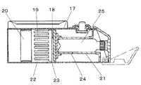
図7は、前記特許文献1に記載された従来の冷温庫の側断面図である。図7に示すように、従来の冷温庫は、箱体17と、熱電変換デバイス18と、放熱器19と、送風装置20と、冷却器21と、結露水受け22と、排水孔23とから構成されている。冷却器21には冷却器21や被冷却物25に生じた結露水を排水孔23へ導く、穴24が設けられている。 FIG. 7 is a side cross-sectional view of a conventional cool / warm chamber described in
以上のように構成された冷温庫について、以下その動作を説明する。 The operation of the cold / hot storage configured as described above will be described below.
熱電変換デバイス18に通電すると、冷却面が吸熱し、冷却器21が冷却され被冷却物25が保冷もしくは冷却される。この時、冷却器21や被冷却物25が箱体17内の貯蔵庫内の空気温度より低下し、さらに露点温度以下になると冷却器21や被冷却物25に結露が生じる。これらの結露水は重力により、穴24を通って落下し、排水孔23から結露水受け22に溜まる。 When the
一方、放熱面では発熱し、放熱器19に熱が伝わり、送風装置20により生じた気流により放熱器19から放熱する。この後、気流は結露水受け22上を通り、結露水を蒸発させる。
しかしながら、上記従来の構成では、放熱器19を通過し、温度を上昇させた気流が結露水受け22上を通過し、結露水を蒸発させるため結露水の蒸発量は少なく、結露水量が多い場合には蒸発しきれないという課題があった。また、放熱器は空気の顕熱変化により熱交換しているため、放熱量が小さいという課題も有していた。 However, in the above-described conventional configuration, when the airflow that has passed through the
本発明は従来の課題を解決するもので、結露水の蒸発量を向上させるとともに、放熱量を向上させた電子式保冷庫を提供することを目的とする。 This invention solves the conventional subject, and it aims at providing the electronic cool box which improved the evaporation amount while improving the evaporation amount of dew condensation water.
上記従来の課題を解決するために、本発明の電子式保冷庫は、放熱器の重力方向反対側端面が冷却器重力方向側端面よりも重力方向側に設置され、排水孔から排出される結露水が放熱器の重力方向反対側端面に送られるように構成したものである。 In order to solve the above-described conventional problems, the electronic cooler of the present invention is configured such that the end surface on the opposite side in the gravitational direction of the radiator is installed closer to the gravitational direction side than the end surface on the cooler gravitational direction side, and condensation is discharged from the drain hole. It is configured such that water is sent to the end surface on the opposite side in the direction of gravity of the radiator.
これによって、冷却器についた結露水を重力によって放熱器へと導き、放熱器の表面上で蒸発させることができる。 Thereby, the dew condensation water attached to the cooler can be guided to the radiator by gravity and can be evaporated on the surface of the radiator.
また本発明は、放熱器を、基板と熱的に接続されたフィンとから構成したもので、これによって、放熱器の表面積を大きくとることができる。 In the present invention, the radiator is composed of fins that are thermally connected to the substrate, whereby the surface area of the radiator can be increased.
また本発明は、前記熱電変換デバイスの発熱面と放熱器とが熱良導材料で熱的に接続されたものである。 In the present invention, the heat generating surface of the thermoelectric conversion device and the radiator are thermally connected with a thermally conductive material.
これによって、熱電変換デバイスの発熱を放熱器に効率よく伝えることができる。 As a result, heat generated by the thermoelectric conversion device can be efficiently transmitted to the radiator.
また本発明は、前記熱良導材料を、金属材料で構成されたもので、これによって、比較的安価に効率よく熱電変換デバイスの発熱を放熱器に伝えることができる。 Further, according to the present invention, the heat conducting material is made of a metal material, whereby heat generated from the thermoelectric conversion device can be efficiently transmitted to the radiator at a relatively low cost.
また本発明は、前記熱良導材料を、ヒートパイプで構成されたもので、これによって、非常に効率よく熱電変換デバイスの発熱を放熱器に伝えることができる。 Further, in the present invention, the heat conducting material is constituted by a heat pipe, whereby the heat generated by the thermoelectric conversion device can be transmitted to the radiator very efficiently.
また本発明は、放熱器を、重力方向反対側端面が結露水供給部から水平方向端面に向かって重力方向に傾斜する形状としたものである。 Moreover, this invention makes a heat radiator the shape where the gravity direction opposite end surface inclines in a gravitational direction toward a horizontal direction end surface from a dew condensation water supply part.
これによって、結露水供給部から放熱器の重力方向反対側端面へ供給された結露水を水平方向へ拡げることができ、放熱器の結露水による濡れ面積を増加させることができる。 Thereby, the dew condensation water supplied from the dew condensation water supply unit to the end surface on the opposite side to the gravity direction of the radiator can be expanded in the horizontal direction, and the wetted area of the radiator due to the dew condensation water can be increased.
また本発明は、前記放熱器における重力方向反対側端面に、結露水が流れる流路を設けたもので、これによって、結露水を気流が通過しにくい放熱器背面に流すのを防ぐことができる。 Moreover, this invention provides the flow path through which dew condensation water flows in the gravity direction opposite end surface in the said heat radiator, By this, it can prevent flowing dew condensation water on the heat radiator back surface which an airflow cannot pass easily. .
また本発明は、前記放熱器の基板のフィン接続表面上に、重力方向反対側面から重力方向に結露水を流す流路を設けたものである。 Moreover, this invention provides the flow path which flows dew condensation water on the fin connection surface of the board | substrate of the said heat radiator from the side surface opposite to a gravitational direction to a gravitational direction.
これによって、結露水が重力方向に設けた流路を流れることにより、飛散させることなく、基板面上を流下させることができる。 As a result, the condensed water can flow down on the substrate surface without being scattered by flowing through the flow path provided in the direction of gravity.
また本発明は、前記放熱器に、重力方向反対側面から重力方向に結露水を流す複数の流路から分岐し重力方向に90度よりも小さい傾斜角で分岐流路を設けたものである。 According to the present invention, the radiator is provided with a branch channel with a tilt angle smaller than 90 degrees in the direction of gravity, branched from a plurality of channels through which condensed water flows in the direction of gravity from the side opposite to the direction of gravity.
これによって、結露水を飛散させることなく、基板面上を流下させるとともに、分岐流路へ流れることにより、基板の広域に結露水を供給することができる。 As a result, the condensed water can be supplied to a wide area of the substrate by flowing down on the substrate surface without scattering the condensed water and flowing to the branch flow path.
また本発明は、前記放熱器に、分岐流路から基板と反対側端面方向に向かってフィン表面上に微細流路を設けたものである。 According to the present invention, the radiator is provided with a fine channel on the fin surface from the branch channel toward the end surface opposite to the substrate.
これによって、基板面上に設けた分岐流路により基板面上に供給された結露水は、フィン表面上に設けた微細流路の毛細管現象によりフィン表面へと供給することができる。 Thereby, the dew condensation water supplied on the substrate surface by the branch flow path provided on the substrate surface can be supplied to the fin surface by the capillary phenomenon of the fine flow path provided on the fin surface.
また本発明は、内部に貯蔵空間を持つ箱体と、二つの伝熱面を持ち一方が吸熱面としてまた他方が発熱面として働く熱電変換デバイスと、前記吸熱面に熱的に接続され前記箱体内もしくは前記貯蔵空間内に設置された冷却器と、前記発熱面に熱的に接続された放熱器と、冷却器や貯蔵空間内に結露した結露水を前記箱体外へ排出する排水孔と、放熱器に気流を送風する送風装置とから構成され、前記送風装置により反重力方向に気流が放熱器を通過するようにしたものである。 The present invention also includes a box having a storage space therein, a thermoelectric conversion device having two heat transfer surfaces, one serving as a heat absorption surface and the other serving as a heat generation surface, and the box thermally connected to the heat absorption surface. A cooler installed in the body or in the storage space; a radiator thermally connected to the heat generating surface; and a drain hole for discharging condensed water condensed in the cooler or the storage space to the outside of the box. And a blower that blows an airflow to the radiator, and the airflow passes through the radiator in the antigravity direction by the blower.
これによって、基板面上やフィン表面上を流下する結露水の流下速度を低減することができ、放熱器による加熱時間を延長することができる。 Thereby, the flow rate of the dew condensation water flowing down on the substrate surface or the fin surface can be reduced, and the heating time by the radiator can be extended.
本発明の電子式保冷庫は、結露水の蒸発量を向上させるとともに、放熱器の放熱能力を向上させることができる。 The electronic cool box of the present invention can improve the heat dissipation capability of the radiator while improving the evaporation amount of condensed water.
請求項1に記載の発明は、内部に貯蔵空間を持つ箱体と、二つの伝熱面を持ち一方が吸熱面としてまた他方が発熱面として働く熱電変換デバイスと、吸熱面に熱的に接続され箱体内もしくは貯蔵空間内に設置された冷却器と、発熱面に熱的に接続された放熱器と、冷却器や貯蔵空間内に結露した結露水を箱体外へ排出する排水孔とから構成され、放熱器の重力方向反対側端面が冷却器重力方向側端面よりも重力方向側に設置され、排水孔から排出される結露水が放熱器の重力方向反対側端面に送られるように構成したものである。 The invention described in
かかる構成とすることにより、冷却器についた結露水を重力によって放熱器へと導き、放熱器の表面上で蒸発させることができ、結露水の蒸発量を向上させるとともに、結露水の蒸発潜熱を利用して放熱するため、放熱器の放熱能力を向上させることができる。 With this configuration, the condensed water attached to the cooler can be guided to the radiator by gravity and evaporated on the surface of the radiator, improving the evaporation amount of the condensed water and reducing the latent heat of evaporation of the condensed water. Since the heat is dissipated by using it, the heat dissipating ability of the radiator can be improved.
請求項2に記載の発明は、前記放熱器を、基板と熱的に接続されたフィンとから構成したものであり、放熱器の表面積を大きくとることができ、結露水の蒸発量を向上させるとともに、放熱器の放熱能力を向上させることができる。 The invention according to
請求項3に記載の発明は、前記熱電変換デバイスの発熱面と放熱器とを、熱良導材料で熱的に接続したものであり、かかる構成によって、前記熱電変換デバイスの発熱を放熱器に効率よく伝えることができ、結露水の蒸発量を向上させるとともに、放熱器の放熱能力を向上させることができる。 The invention according to
請求項4に記載の発明は、前記熱良導材料を金属材料で構成したもので、比較的安価に効率よく熱電変換デバイスの発熱を放熱器に伝えることができ、結露水の蒸発量を向上させるとともに、放熱器の放熱能力を向上させることができる。 In the invention according to
請求項5に記載の発明は、前記熱良導材料をヒートパイプで構成したもので、非常に効率よく熱電変換デバイスの発熱を放熱器に伝えることができ、結露水の蒸発量を向上させるとともに、放熱器の放熱能力を向上させることができる。 The invention according to
請求項6に記載の発明は、前記放熱器を、重力方向反対側端面が結露水供給部から水平方向端面に向かって重力方向に傾斜する構成としたものであり、結露水供給部から放熱器の重力方向反対側端面へ供給された結露水を水平方向へ拡げることができ、その結果、放熱器の結露水による濡れ面積を増加させることができ、結露水の蒸発量を向上させるとともに、放熱器の放熱能力を向上させることができる。 The invention according to
請求項7に記載の発明は、前記放熱器において、重力方向反対側端面に結露水が流れる流路を設けたもので、結露水を気流が通過しにくい放熱器背面に流すのを防ぐことができ、結露水の蒸発量を向上させるとともに、放熱器の放熱能力を向上させることができる。 The invention according to
請求項8に記載の発明は、前記放熱器の基板のフィン接続表面上に、重力方向反対側面から重力方向に結露水を流す流路を設けたもので、結露水が重力方向に設けた流路を流れることにより、飛散させることなく、基板面上を流下させることができ、結露水の蒸発量を向上させるとともに、放熱器の放熱能力を向上させることができる。 According to an eighth aspect of the present invention, a flow path is provided on the fin connection surface of the substrate of the radiator to allow the condensed water to flow in the direction of gravity from the side opposite to the direction of gravity. By flowing through the path, it is possible to flow down on the substrate surface without scattering, improving the evaporation amount of condensed water, and improving the heat dissipation capability of the radiator.
請求項9に記載の発明は、前記放熱器に、重力方向反対側面から重力方向に結露水を流す複数の流路から分岐し重力方向に90度よりも小さい傾斜角で分岐流路を設けたもので、結露水を飛散させることなく、基板面上を流下させるとともに、分岐流路へ流れることにより、基板の広域に結露水を供給することができ、結露水の蒸発量を向上させるとともに、放熱器の放熱能力を向上させることができる。 According to the ninth aspect of the present invention, the radiator is branched from a plurality of channels through which condensed water flows in the direction of gravity from the side opposite to the direction of gravity, and a branch channel is provided at an inclination angle smaller than 90 degrees in the direction of gravity. Therefore, it is possible to supply condensed water over a wide area of the substrate by flowing down the substrate surface without splashing the condensed water and flowing to the branch flow path, improving the evaporation amount of the condensed water, The heat dissipation capability of the radiator can be improved.
請求項10に記載の発明は、前記放熱器に、前記分岐流路から基板と反対側端面方向に向かってフィン表面上に微細流路を設けたもので、基板面上に設けた分岐流路により基板面上に供給された結露水は、フィン表面上に設けた微細流路の毛細管現象によりフィン表面へと供給することができ、結露水の蒸発量を向上させるとともに、放熱器の放熱能力を向上させることができる。 The invention according to
請求項11に記載の発明は、内部に貯蔵空間を持つ箱体と、二つの伝熱面を持ち一方が吸熱面としてまた他方が発熱面として働く熱電変換デバイスと、前記吸熱面に熱的に接続され前記箱体内もしくは前記貯蔵空間内に設置された冷却器と、前記発熱面に熱的に接続された放熱器と、冷却器や貯蔵空間内に結露した結露水を前記箱体外へ排出する排水孔と、放熱器に気流を送風する送風装置とから構成され、前記送風装置により反重力方向に気流が放熱器を通過するようにしたものである。 The invention according to claim 11 includes a box having a storage space inside, a thermoelectric conversion device having two heat transfer surfaces, one serving as a heat absorption surface and the other serving as a heat generation surface, and thermally acting on the heat absorption surface. A cooler that is connected and installed in the box or in the storage space, a radiator that is thermally connected to the heat generating surface, and dew condensation in the cooler or the storage space is discharged outside the box. And a blower that blows airflow to the radiator. The blower allows the airflow to pass through the radiator in the antigravity direction.
かかる構成とすることにより、基板面上やフィン表面上を流下する結露水の流下速度を低減することができ、その結果、放熱器による加熱時間を延長させて結露水の蒸発量を向上させるとともに、放熱器の放熱能力を向上させることができる。 By adopting such a configuration, it is possible to reduce the flow rate of the dew condensation water flowing down on the substrate surface and the fin surface, and as a result, the heating time by the radiator is extended and the evaporation amount of the dew condensation water is improved. The heat dissipating ability of the radiator can be improved.
以下、本発明の実施の形態について、図面を参照しながら説明する。なお、この実施の形態によってこの発明が限定されるものではない。 Hereinafter, embodiments of the present invention will be described with reference to the drawings. The present invention is not limited to the embodiments.
(実施の形態1)
図1は、本発明の実施の形態1における電子式保冷庫の背面図であり、図2は図1のA−A線による断面図である。(Embodiment 1)
FIG. 1 is a rear view of the electronic cool box in
図1および図2において、箱体1は断熱箱であって内部に貯蔵空間1aを持っており、食品や薬品等を収納することができる。 1 and 2, the
熱電変換デバイス2は、吸熱面2aと発熱面2bを持っており、冷却器3は吸熱面2aと熱的に接続されている。 The
前記冷却器3は、前記箱体1内部の貯蔵空間1a内に設置されている。排水孔4は冷却器3の重力方向側に設置されている。 The
放熱器5は、基板6と該基板6と熱的に接続され、前記基板6から略垂直に設けられたフィン7とから構成されており、この放熱器5の重力方向反対側端面8が、前記冷却器3の重力方向側端面よりも重力方向側で、かつ排水孔4の結露水排出口よりも重力方向側で結露水が放熱器5の重力方向反対側端面8に供給できるように設置されている。そして、前記放熱器5は、金属等の熱伝導率の大きい材料で作られており、成形のし易さや安価という観点からアルミニウムやアルミニウム合金が適している。 The
また、前記基板6とフィン7は一体で成形されているものがよく、アルミニウム合金を用いた押出成型品が適している。その他、グラファイト等も採用でき、より軽量で高性能化が図れる。また、基板6にはヒートパイプ等の冷媒の相変化を用いた高熱伝導部材を用いても良い。 The
図3は前記放熱器の正面図、図4は前記放熱器の上面図、図5は図3のB−B線による断面図である。図3から図5を用いて、前記放熱器5の構成を詳細に説明する。 3 is a front view of the radiator, FIG. 4 is a top view of the radiator, and FIG. 5 is a sectional view taken along line BB in FIG. The configuration of the
前記重力方向反対側端面8は、前記排水孔4の結露水供給部から水平方向端面に向かって重力方向に傾斜しており、重力方向反対側端面8上には、前記放熱器5の長手方向に重力方向反対側端面流路9が設けられている。また、前記基板6のフィン7接続面上には、前記重力方向反対側端面8から重力方向に延びる流路10が設けられており、さらに前記流路10から分岐し、重力方向に90度よりも小さい傾斜角で略八の字状に分岐流路11が設けられている。また、前記分岐流路11から基板6と反対側端面方向に向かってフィン7表面上に重力方向に傾斜した微細流路12が設けられている。 The gravitational direction
熱伝導部材13は、熱電変換デバイス2の発熱面2bと放熱器8の基板6とを熱的に接続しており、本実施の形態では金属材料を用いている。この金属材料は、安価という観点からはアルミニウムが適しており、高熱伝導材料という観点からは銅が適している。 The heat conducting member 13 thermally connects the
放熱器5に気流を送風する送風装置14は、前記放熱器5の上方に設置されており、反重力方向に気流が流動するように動作する。本実施の形態では送風装置14として軸流ファンを用いているが、クロスフローファンなどを用いても良い。 The
以上のように構成された電子式保冷庫について、以下その動作、作用を説明する。 The operation and action of the electronic cooler configured as described above will be described below.
熱電変換デバイス2に電流を流すことにより、冷却面2aが冷却され、冷却器3が冷却される。そして、冷却器側送風装置15が動作し、これにより貯蔵空間1a内の空気と冷却器3と熱交換させ、前記貯蔵空間1aを冷却する。この時、冷却器3の温度が貯蔵空間1a内の空気の露点温度以下になると冷却器3に結露が生じる。この結露水は重力により、冷却器3の重力方向側に設置された排水孔4に収集され、貯蔵空間1a外に排出される。 By passing an electric current through the
一方、前記熱電変換デバイス2の発熱面2bは発熱し、熱伝導部材13を介して、放熱器5の基板6に熱が伝わり、フィン7に熱が拡がる。この時、排水孔4を通り、重力によって重力方向反対側端面8に供給された結露水は、重力方向反対側端面流路9へと入る。 On the other hand, the
その結果、重力方向反対側端面8が結露水供給部から水平方向端面に向かって重力方向に傾斜しているため、結露水は一部を流路10に分流しながら、重力により水平方向端面に向かって流れ、放熱器5の水平方向へ拡がる。 As a result, the
次に、前記流路10に分流された結露水は基板6上を重力方向へと流れ、略八の字状の分岐流路11に分流され、前記基板6全体に拡がる。その後、分岐流路11を流れる結露水は毛細管力と重力により、フィン表面上微細流路12へ供給され、フィン7全体へと拡がる。 Next, the dew condensation water divided into the
このように、結露水は放熱器5全体へと拡がるとともに、前述した熱電デバイス2の発熱面2bの熱が放熱器5へと伝わり、結露水を加熱し、蒸発させる。さらに、放熱器側送風装置14により、反重力方向へ放熱器5内に気流を流すことにより、結露水の流下速度を小さくし、前記放熱器5による加熱時間を延長するとともに、気流により結露水の蒸発を促進することができる。 As described above, the dew condensation water spreads over the
以上のように本実施の形態は、放熱器5の重力方向反対側端面8が、冷却器3重力方向側端面よりも重力方向側に設置され、また、排水孔4から排出される結露水が、前記放熱器5の重力方向反対側端面流路9に供給できるように設置するとともに、前記放熱器5は、基板6とフィン7から構成され、さらに、前記放熱器5の重力方向反対側端面8が結露水供給部から水平方向端面に向かって重力方向に傾斜しており、重力方向反対側端面8から重力方向に結露水を流す流路10を放熱器5の基板6のフィン7接続表面上に設け、また、前記流路10から分岐し、かつ重力方向に90度よりも小さい傾斜角で分岐流路11を設け、さらに基板6と反対側端面方向に向かってフィン7表面上に微細流路12を設けたものである。また、本実施の形態は、金属製の熱伝導部材13で熱電変換デバイス2の発熱面2bと放熱器8の基板6とを熱的に接続し、放熱器側送風装置14で反重力方向へ放熱器5内に気流を流すようにしたものである。 As described above, in the present embodiment, the
これらの構成により、冷却器3で生じた結露水を放熱器5全体に拡げ、加熱時間を延長し、熱電変換デバイス2の発熱面2bの発熱で蒸発させる結露水量を大幅に向上することができるとともに、蒸発潜熱を用いて放熱することにより放熱器5の放熱能力も向上することができる。 With these configurations, the condensed water generated in the cooler 3 can be spread over the
(実施の形態2)
次に、実施の形態2について説明するが、先の実施の形態1と同一の構成のものについては同一の符号を付して詳細な説明は省略する。図6は、本発明の本実施の形態2における電子式保冷庫の側断面図である。(Embodiment 2)
Next, the second embodiment will be described. The same components as those of the first embodiment are denoted by the same reference numerals, and detailed description thereof is omitted. FIG. 6 is a side sectional view of the electronic cool box in the second embodiment of the present invention.
熱伝導部材16はヒートパイプで構成されており、熱電変換デバイス2の発熱面2bと放熱器5の基板6とを熱的に接続している。 The heat conducting member 16 is formed of a heat pipe, and thermally connects the
以上のように構成された電子式保冷庫について、以下実施の形態1と異なる動作、作用を説明する。 Regarding the electronic cooler configured as described above, operations and effects different from those of the first embodiment will be described below.
熱電変換デバイス2の発熱面2bの発熱をヒートパイプ製熱伝導部材16に伝え、放熱器5の基板6に伝える。この時、熱伝導部材16はヒートパイプ内の冷媒の蒸発潜熱を利用し熱搬送を行うため、非常に効率よく、大量に熱を伝えることができる。 Heat generated from the
以上のように本実施の形態ではヒートパイプ製の熱伝導部材16で構成されたことにより、発熱面2bの発熱を放熱器5に効率よく、大量に伝えることができ、結露水の蒸発量を向上させるとともに、放熱器5の放熱量を向上することができる。 As described above, in the present embodiment, the heat conduction member 16 made of heat pipe can efficiently transmit a large amount of heat generated on the
以上のように、本発明にかかる電子式保冷庫は、結露水を蒸発させ排出することが可能となるので、電子式冷温庫や冷蔵庫、薬品保管庫や理化学機器等の用途にも適用できる。 As described above, the electronic cool box according to the present invention can evaporate and discharge the condensed water, and thus can be applied to uses such as an electronic cool box, a refrigerator, a chemical storage box, and a physics and chemistry instrument.
1 箱体
2 熱電変換デバイス
2a 冷却面
2b 発熱面
3 冷却器
4 排水孔
5 放熱器
6 基板
7 フィン
8 重力方向反対側端面
9 重力方向反対側端面流路
10 流路
11 分岐流路
12 フィン表面上微細流路
13 熱伝導部材
14 放熱器側送風装置
16 熱伝導部材DESCRIPTION OF
Claims (11)
Translated fromJapanesePriority Applications (1)
| Application Number | Priority Date | Filing Date | Title |
|---|---|---|---|
| JP2004276860AJP2006090633A (en) | 2004-09-24 | 2004-09-24 | Electronic cold storage |
Applications Claiming Priority (1)
| Application Number | Priority Date | Filing Date | Title |
|---|---|---|---|
| JP2004276860AJP2006090633A (en) | 2004-09-24 | 2004-09-24 | Electronic cold storage |
Publications (1)
| Publication Number | Publication Date |
|---|---|
| JP2006090633Atrue JP2006090633A (en) | 2006-04-06 |
Family
ID=36231789
Family Applications (1)
| Application Number | Title | Priority Date | Filing Date |
|---|---|---|---|
| JP2004276860APendingJP2006090633A (en) | 2004-09-24 | 2004-09-24 | Electronic cold storage |
Country Status (1)
| Country | Link |
|---|---|
| JP (1) | JP2006090633A (en) |
Cited By (2)
| Publication number | Priority date | Publication date | Assignee | Title |
|---|---|---|---|---|
| JP2015521272A (en)* | 2012-05-07 | 2015-07-27 | フォノニック デバイセズ、インク | System and method for thermoelectric heat exchange system |
| US10458683B2 (en) | 2014-07-21 | 2019-10-29 | Phononic, Inc. | Systems and methods for mitigating heat rejection limitations of a thermoelectric module |
- 2004
- 2004-09-24JPJP2004276860Apatent/JP2006090633A/enactivePending
Cited By (4)
| Publication number | Priority date | Publication date | Assignee | Title |
|---|---|---|---|---|
| JP2015521272A (en)* | 2012-05-07 | 2015-07-27 | フォノニック デバイセズ、インク | System and method for thermoelectric heat exchange system |
| US10012417B2 (en) | 2012-05-07 | 2018-07-03 | Phononic, Inc. | Thermoelectric refrigeration system control scheme for high efficiency performance |
| JP2018159540A (en)* | 2012-05-07 | 2018-10-11 | フォノニック デバイセズ、インク | System and method for thermoelectric heat exchange system |
| US10458683B2 (en) | 2014-07-21 | 2019-10-29 | Phononic, Inc. | Systems and methods for mitigating heat rejection limitations of a thermoelectric module |
Similar Documents
| Publication | Publication Date | Title |
|---|---|---|
| US7369410B2 (en) | Apparatuses for dissipating heat from semiconductor devices | |
| US7382047B2 (en) | Heat dissipation device | |
| US7926553B2 (en) | Cooling system for electronic devices, in particular, computers | |
| KR20190082523A (en) | Cooling device using thermo-electric module | |
| US8297062B2 (en) | Heat-dissipating device for supplying cold airflow | |
| JP4953075B2 (en) | heatsink | |
| WO2015146110A1 (en) | Phase-change cooler and phase-change cooling method | |
| Başaran | Experimental investigation of R600a as a low GWP substitute to R134a in the closed-loop two-phase thermosyphon of the mini thermoelectric refrigerator | |
| CN107076483B (en) | Refrigeration device | |
| JP2010080507A (en) | Electronic apparatus | |
| US7447025B2 (en) | Heat dissipation device | |
| JP2007115917A (en) | Heat dispersion plate | |
| JP2006090633A (en) | Electronic cold storage | |
| TW202438637A (en) | Heat pipe and heat dissipation device | |
| JP5624771B2 (en) | Heat pipe and heat sink with heat pipe | |
| JP2008218513A (en) | Cooling system | |
| JP2006090635A (en) | Electronic cold storage | |
| JP3893651B2 (en) | Boiling cooling device and casing cooling device using the same | |
| JP2006196786A (en) | Heat sink with heat pipe | |
| JP2008244320A (en) | Cooling system | |
| EP2363882A1 (en) | Heat-dissipating device for supplying cold airflow | |
| TWI858579B (en) | Radiator | |
| CN210835950U (en) | Heat dissipation device and electronic equipment | |
| JP5934886B2 (en) | Cooling device and electric vehicle equipped with the same | |
| KR100407049B1 (en) | Refrigerator Utilizing Peltier Element |