JP2006085391A - SIM reader / writer - Google Patents
SIM reader / writerDownload PDFInfo
- Publication number
- JP2006085391A JP2006085391AJP2004268874AJP2004268874AJP2006085391AJP 2006085391 AJP2006085391 AJP 2006085391AJP 2004268874 AJP2004268874 AJP 2004268874AJP 2004268874 AJP2004268874 AJP 2004268874AJP 2006085391 AJP2006085391 AJP 2006085391A
- Authority
- JP
- Japan
- Prior art keywords
- sim
- writer
- reader
- contact
- liquid crystal
- Prior art date
- Legal status (The legal status is an assumption and is not a legal conclusion. Google has not performed a legal analysis and makes no representation as to the accuracy of the status listed.)
- Granted
Links
Images


Abstract
Translated fromJapaneseDescription
Translated fromJapanese本発明は、USB用コネクタを有し、接触と非接触のインターフェースを備えるSIMを着脱可能に装着し、SIMが保持するデータ内容を液晶ディスプレイに表示可能なSIMリーダライタに関する。このようなSIMリーダライタは、第1にパーソナルコンピュータ(PC)等 のアクセス権限認証用途に使用でき、第2に施設、交通機関等の非接触ゲート管 理や非接触ショッピング等の決済取引に適用でき、第3に液晶ディスプレイに各 種情報を表示させることができるので、そのような情報表示が求められる媒体、例えば、各種取引の記録表示、定期券や乗車券、各種施設入場券等に好適に用い得るものである。従って、本発明の関連する技術分野は、SIMリーダライタやSIMの製造・ 利用の分野、あるいは定期券や乗車券、入場券の発券や取り扱い、または利用分野に関する。 The present invention relates to a SIM reader / writer that has a USB connector, is detachably mounted with a SIM having a contact and non-contact interface, and can display data content held by the SIM on a liquid crystal display. Such a SIM reader / writer can be used for authentication of access authority such as personal computers (PCs) first, and secondly for settlement transactions such as contactless gate management and contactless shopping for facilities and transportation facilities. Third, since various types of information can be displayed on the liquid crystal display, it is suitable for media that require such information display, such as record display of various transactions, commuter passes, boarding tickets, various facility admission tickets, etc. It can be used for. Therefore, the technical field related to the present invention relates to the field of manufacturing and using SIM reader / writers and SIMs, or the field of issuing and handling commuter tickets, boarding tickets, admission tickets, and usage.
近年、ISO7816−2、ISO7816−3で規定される接触と、USB(ユニバーサル・シリアル・バス)接触とのデュアルインターフェースのICカードが開発されている(特許文献1)。USBインターフェースを持つICカードは、パソコンなどのUSB対応の機器との接続を容易にし、社員証カードなどでネットワークアクセス用IDカード として注目されはじめている。 In recent years, a dual interface IC card having a contact defined by ISO 7816-2 and ISO 7816-3 and a USB (Universal Serial Bus) contact has been developed (Patent Document 1). An IC card having a USB interface facilitates connection with a USB-compatible device such as a personal computer, and has begun to attract attention as an ID card for network access such as an employee ID card.
一方、e−Tokenと呼ばれるICチップを内蔵したネットワークアクセス 用IDモジュールが使用されている。USB接触インターフェースを持ち、パソ コン(PC)のUSBコネクタに差し込みプラグアンドプレイ、すなわち煩わしい操作を必要とせずに、ネットワークセキュリティを確保したシステムに使用されている。ドングルと呼ばれることもあり、携帯電話のストラップやキーホルダーとともに持ち歩ける利便性がある。 On the other hand, an ID module for network access incorporating an IC chip called e-Token is used. It has a USB contact interface, is plugged into a USB connector of a personal computer (PC), and is used in a system that secures network security without requiring troublesome operations. Sometimes called a dongle, it is convenient to carry with a cell phone strap or key chain.
他方、携帯電話には小型のSIMやUIM、USIMカードと呼ばれるセキュリティIDモジュールが組み込まれてきている。日本でも最新の携帯電話には組 み込まれて既に実用化されている。UIM(User Identity Module) は、携帯電話会社が発行する契約者情報を記 録した小型のICカードであって、携帯電話機に組み込んで利用者の識別に使用する。 On the other hand, a security ID module called a small SIM, UIM, or USIM card has been incorporated in a mobile phone. In Japan, it has already been put into practical use by incorporating it into the latest mobile phones. A UIM (User Identity Module) is a small IC card that records subscriber information issued by a mobile phone company, and is used to identify users by incorporating it into a mobile phone.
これは同様の機能を持つSIM(Subscriber Identity Module)から機能拡張が行われたもので、契約者情報以外に電話帳などのプライベート情報やクレジット 決済用の個人識別情報などを暗号化して登録することが可能となっている。SIMをベースにしていることからUSIM(Universal SIM)と呼ばれることもある。SIMはGSM携帯電話サービスの利用を目的とするが、UIMは、例えば、アメリカのcdma2000携帯電話機に差し込んで国際ローミングサー ビスを受けるといった使用方法が考えられている。いずれにしても、このようなSIMまたはUIMは既存技術が有るので製造や発行処理が容易である。 This is an extension of functionality from a SIM (Subscriber Identity Module) that has the same function. In addition to subscriber information, private information such as phone books and personal identification information for credit payments are encrypted and registered. Is possible. Because it is based on SIM, it is sometimes called USIM (Universal SIM). The SIM is intended to use the GSM mobile phone service, but the UIM can be used, for example, by inserting it into an American cdma2000 mobile phone and receiving an international roaming service. In any case, since such SIM or UIM has existing technology, it is easy to manufacture and issue.
前述のキーホルダー型IDモジュールや特許文献1の携帯物品は、非接触通信機能を持たないので、改札ゲートやドアゲートを非接触で開閉する等の用途に兼用できないという使い勝手の悪さがある。そこで、本願出願人は、先に、ISO7816で規定される接触と、ISO14443非接触のインターフェースを備えるUSBコネクタ付きSIMホルダーについて、特許文献2において提案している。また、ISO7816で規定される接触と、ISO14443非接触、USB接触の3種のインターフェースを備えるICモジュール、SIMホルダー、SIM等について、特許文献3、4において提案している。 Since the above-mentioned key holder type ID module and the portable article of
上記特許文献2、特許文献3に提案のSIMホルダーは、表示部を有しないのでSIMが保持する情報内容を可視的に表示できない問題がある。また、上記特許文献4に提案のSIMリーダライタは、データの読取りがICチップからのい読取りに限定されてしまうという問題がある。しかし、ICチップからデータを読み取る装置は、未だ普及率が高くないのが現状である。一方、バーコードリーダ等の光学的読取り装置は、普及率が高く、これを利用したいという要望がある。 Since the SIM holders proposed in
そこで、本発明は、チケット情報等をディスプレイに光学的に機械読取可能な状態で表示することが可能なSIMリーダライタを提供することを課題とする。 Therefore, an object of the present invention is to provide a SIM reader / writer that can display ticket information and the like on a display in an optically machine-readable state.
上記課題を解決するため、本発明では、SIMリーダライタを、USB用コネクタを有し、ISO7816−2、ISO7816−3で規定する接触、ISO14443で規定する非接触インターフェースを備えるSIMを着脱可能に装着するSIMリーダライタであって、当該SIMリーダライタは、SIMに記録されたチケット情報をバーコードに変換する機能と、当該バーコードを液晶ディスプレイに表示する機能を備えると共に、所定時間の経過後は、液晶ディスプレイからバーコードを消去する機能を有する構成としたことを特徴とする。 In order to solve the above problems, in the present invention, a SIM reader / writer is detachably mounted with a SIM having a USB connector and a contact defined by ISO 7816-2 and ISO 7816-3, and a non-contact interface defined by ISO 14443. The SIM reader / writer has a function of converting ticket information recorded in the SIM into a barcode, a function of displaying the barcode on a liquid crystal display, and after a predetermined time has elapsed. Further, the present invention is characterized by having a function of erasing the barcode from the liquid crystal display.
本発明によれば、接触、非接触インターフェースを備えたSIMリーダライタにおいて、SIMに記録されたチケット情報をバーコードに変換して、ディスプレイに表示するようにしたので、既存のバーコードリーダを利用して読み取りを行うことが可能となり、接触・非接触ICカードリーダライタ以外でも読取りできるため、情報の読取り機会が増大する。また、バーコードを所定時間経過後に消去するようにしたので、その後に不正に読取られることを防止することができる。 According to the present invention, in a SIM reader / writer having a contact / non-contact interface, the ticket information recorded in the SIM is converted into a bar code and displayed on the display, so that an existing bar code reader is used. Thus, reading can be performed, and reading can be performed by other than a contact / non-contact IC card reader / writer. Further, since the bar code is erased after a predetermined time has elapsed, it can be prevented from being read illegally thereafter.
以下、本発明の好適な実施形態について、図面を参照して詳細に説明する。
(液晶ディスプレイ付きSIMリーダライタ)
まず、本発明の前提となる液晶ディスプレイ付きSIMリーダライタについて説明する。図1は、液晶ディスプレイ付きSIMリーダライタのブロック構成を示す図、である。図2は、液晶ディスプレイ付きSIMリーダライタの外形を示す図、図3〜図6は、SIMリーダライタ内の構成を示す図、図7は、SIMを示す平面図、である。DESCRIPTION OF EMBODIMENTS Hereinafter, preferred embodiments of the present invention will be described in detail with reference to the drawings.
(SIM reader / writer with LCD)
First, a SIM reader / writer with a liquid crystal display which is a premise of the present invention will be described. FIG. 1 is a diagram showing a block configuration of a SIM reader / writer with a liquid crystal display. FIG. 2 is a diagram showing an outer shape of a SIM reader / writer with a liquid crystal display, FIGS. 3 to 6 are diagrams showing the configuration of the SIM reader / writer, and FIG. 7 is a plan view showing the SIM.
図1のように、液晶ディスプレイ付きSIMリーダライタ(以下、「SIMリーダライタ」と略称する。)1は、SIM2を着脱可能に装着し、制御用ICチップ3を有している。制御用ICチップ3は、CPUとメモリを有すると共に、ISO7816ドライバ31と液晶ディスプレイ駆動用の液晶ドライバ32、および赤外通信用の赤外線ドライバ33を有している。ただし、これらの全てが一体にICチップ化されているものには限られない。SIM2の信号は、リーダライタ(R/W)端子板12とリレー8を介して制御用ICチップ3に接続し、USBポート25からの信号は、USB/ISO7816変換IC10とリレー8を介して制御用ICチップ3に接続する。 As shown in FIG. 1, a SIM reader / writer with a liquid crystal display (hereinafter abbreviated as “SIM reader / writer”) 1 has a
リーダライタ端子板12は、SIM2が備える接触端子板の8端子と接続する 構造を有している。接触端子の場合、予備端子となっているC4とC8端子が、 SIMリーダライタのケーシング内のアンテナコイル11に接続するようにされている。アンテナコイル11は、ISO14443TypeA,Bに準拠した非接触通信を行うためのものである。SIMリーダライタ1は、液晶ディスプレイ4や制御用ICチップ3等の駆動電源としてバッテリ(二次電池)7を備えることが好ましい。バッテリ7には薄 型のリチウムイオン電池を好ましく使用できる。スイッチボタン41は電源のオン−オフフ、スイッチボタン42は、表示選択や動作決定のために用いられる。 The reader /
SIMリーダライタ1は、USBコネクタがパーソナルコンピュータ(PC)のUSBポート25に挿入されている場合は、バッテリ7は接続されないようになっている。したがって、この場合は、スイッチボタン41をオンしても制御用 ICチップ3のCPUは動作せず液晶ディスプレイ4も表示されない。液晶ディスプレイ4は、PCに接続していない場合であって、スイッチボタン41をオンした場合にのみ表示される。 The SIM reader /
この場合(電源ボタンオン時)には、リレー8はCPUとリーダライタ端子板 12を接続する。USBコネクタがUSBポートに挿入されているUSB駆動時は、リレー8は制御用ICチップ3のCPUとUSBポート25を接続する。また、アンテナコイル11によりISO14443通信中に電源ボタンがオフ されたり、USBコネクタがUSBポート25に挿入された場合には、ハードウェアリセットがかかり、SIMはATR(answer to reset )を返す。すなわち 、非接触通信は強制的に中断されるようになっている。 In this case (when the power button is on), the relay 8 connects the CPU and the reader /
SIMリーダライタ1は、赤外線通信手段を備えることができる。赤外線通信手段は、制御ICチップ3の赤外線ドライバ33により制御され、赤外線受発信部5は、赤外線発光部と受光部、およびフィルタ等を備え、これと同様な構成で受発信部を備える外部電子機器と交信してデータの送受信をすることができる。この場合、SIM2の情報は制御用ICチップ3により処理され、赤外線受発信部5の発光部により光電変換されて外部電子機器に送信される。他方、外部電子機器からの信号は受光部が光電変換し、制御用ICチップ3を経てSIM2に送信される。これにより、ISO14443非接触よりも長い近距離間における非接触通信が可能となる。 The SIM reader /
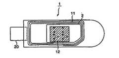
SIMリーダライタはどのような外形であっても構わないが、携帯し易い形状としては、図2のように、USBコネクタ20の挿入方向とSIM2の挿入方向が直線状にあるのが好ましいと考えられる。図2(A)のように、表面に液晶ディスプレイ4を有し、左端部にはUSBコ ネクタ20を有し、右端部にはSIM2の挿入口15を有している。挿入口15の手前部分に液晶ディスプレイ4よりは一段低くなった段部16を設けている。SIM挿入の際、この段部16にSIM2をあてがえばSIM2の挿入を容易にできる。液晶ディスプレイ4と挿入口15の間にスイッチボタン41,42が設けられている。符号14は電源用のLED表示である。SIMリーダライタ1を携帯する際は、キー取り付け穴17に、ストラップ等を通せば、SIM2の不用意な脱落を防止できる。 The SIM reader / writer may have any outer shape, but as a shape that is easy to carry, it is preferable that the insertion direction of the
液晶ディスプレイ4は、SIM2のICチップが保持する情報をスイッチボタ ン42の操作により順次表示するようにされている。表示内容は、SIMの搭載するアプリケーションソフトによって異なるが、例えば、電子マネー201の場合は残高、支払い明細等であり、電子チケット202の場合は、利用日付けや会場、開演時間、指定座席等の表示であり、定期券用途の場合は、通用区間や通用期間、使用者等の表示となる。このようにSIM2は複数アプリケーションを搭載できることが好ましい。液晶ディスプレイ4には、ドットマトリクスタイプの反射型カラー液晶表示を採用でき、図形表示も可能である。液晶ディスプレイ4の厚みは、1.0mm〜1.5mm程度となる。表示面積は、幅20〜30mmから長さ50〜70mm 程度のものにできる。なお、液晶ディスプレイに限らず、有機ELや電子ペーパーなど、薄型で消費電力の少ない表示装置を代替して利用することができる。 The liquid crystal display 4 sequentially displays information held by the IC chip of the
図2(B)は、図2(A)のA−A線断面を示す。この場合は、SIM2が装着されている状態を示している。SIM2と液晶ディスプレイ4との間には、リーダライタ(R/W)端子板12があって、SIM2の接触端子板22との接触が確保される。リーダライタ端子板12は液晶基板下の全面に設けて配線基板を兼ねるようにしても良い。SIMリーダライタ1は、液晶ディスプレイ4やリーダライタ端子板12を備える上蓋部18と下側ケース部19を分割して成型し、配線基板等を組み込んだ後に組み合わせて一体にすることが多い。図示してないが、アンテナコイル11は前記配線基板の周囲に配線したり、上蓋部18や下側ケース部19の内面に配 線させることができる。 FIG. 2B shows a cross section taken along line AA of FIG. In this case, a state where the
SIMリーダライタ1の裏面には、特別な部品を設けないので、図示していな いが、電源充電のための機構部等を設けることができる。また、下側ケース部19を透明樹脂で成型すれば、後述するようにSIMに設けた顔写真やネームプリントを透視することができる。 Since no special parts are provided on the back surface of the SIM reader /
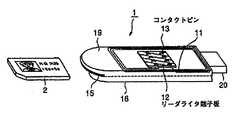
図3〜図6は、SIMリーダライタ内の構成を示す図であって、液晶ディスプレイ4の背面において、リーダライタ端子板12とアンテナコイル11の関係を示している。図3はSIM2の接触端子板22面側斜視図、図4は同平面図、図5はSIM2の接触端子板とは反対面側斜視図、図6は同平面図、である。図3、図4のように、アンテナコイル11はケーシングの上蓋部18の内周等 に沿うように配線され、その末端はリーダライタ端子板12のC4とC8端子に接続するようにされている。SIM2は、図3の右側から挿入してリーダライタ端子板12の下側に入って固定されるようにされている。 3 to 6 are diagrams showing the configuration inside the SIM reader / writer, and the relationship between the reader /
図3、図4において、USBコネクタ20への配線は省略されているが、C5(GND)、C1(Vcc)、C2(RST)、C7(I/O)が、USB/ISO7816変換IC10に導かれることになる。前述した特許文献1には、USB機能を有するICチップが記載され、USB(D+)がC4端子を、USB(D−)がC8端子を利用する例が記載されているが、本発明のSIMリーダライタ1は、USB/ISO7816変換IC10を使用するので、従来機能のデュアルICモジュールを使用できる。また、アンテナコイル11の端子には、C4とC8端子を利用するので、8端子以上の特設端子板を有する端子をSIM2やリーダライタに使用しない利点がある。 3 and 4, wiring to the
図5のように、リーダライタ端子板12の背面には8個のコンタクトピン13が突出していて、SIM2の接触端子板22と接触するようにされている。図6は、SIM2をSIMリーダライタ1に装着した後の状態である。SIM2は、端子板12の背面であって、下側ケース19に沿って挿入されるので、下側ケース19が透明樹脂であれば、SIM2の顔写真加工27等を視認することができる。 As shown in FIG. 5, eight
前記のように、PCに接続している際は、非接触通信機能は遮断されるが、非接続時には、非接触インターフェースを使いコンビニやレストランでの支払いや交通機関の改札や施設の入退室管理に利用することができる。赤外線通信手段を備える場合は、ISO14443による非接触通信よりも長い距離での通信が可能となる。一方、PCに直接接続でき、周辺機器として別途リーダライタを必要としない利点がある。 As mentioned above, the contactless communication function is cut off when connected to a PC, but at the time of disconnection, payment at convenience stores and restaurants, transportation ticket gates, and facility entrance / exit management using the contactless interface. Can be used. When the infrared communication means is provided, communication over a longer distance than non-contact communication according to ISO 14443 is possible. On the other hand, there is an advantage that it can be directly connected to a PC and does not require a separate reader / writer as a peripheral device.
図7は、本発明に使用するSIMを示す平面図である。図7(A)は接触端子板22を有する表面側、図7(B)はその反対側面を示す。図7(A)のように、SIM2は長辺L1が25mm、短辺L2が15mm程度の基板21からなるものである。厚みは、1.0mm以内で、通常は0.76mmの均一な薄板状のものである。接触端子板22の背面基板中には、接触、非接触デュアルモードのICモジュールが装着されている。矩形状SIMの一端隅角部に切り欠き23を有するのは、SIM2をSIMリーダライタ1に装着する際の位置合わせを容易にするためのものである。 FIG. 7 is a plan view showing a SIM used in the present invention. FIG. 7A shows the surface side having the
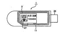
図7(B)のように、SIM2の接触端子板22とは反対側面には、顔写真加工27やネームプリント28、番号プリント29を設けることができ、所有者の識別を容易にできると共に、SIMリーダライタ1の下側ケース部を透明にする場合にはSIMを装着した状態で利用者を視覚的に識別することができる。SIM2は、マルトス(商標)対応のものとすることで、電子マネーや電子チケット、社員証等の複数アプリケーションを搭載して使用することができる。 As shown in FIG. 7B, a
(本発明に係るSIMリーダライタ)
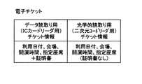
本発明に係るSIMリーダライタは、上記構成のSIMリーダライタにおいて、さらに、電子チケットをバーコードに変換して、表示させることを特徴とする。本実施形態では、バーコードとして二次元バーコードを用いることとする。また、二次元バーコードとしても、公知の種々のものを使用することができるが、例えば、QRコードを使用することができる。本発明に係るSIMリーダライタでは、上記電子チケット202として、利用日付けや会場、開演時間、指定座席等のチケット情報を記録する。チケット情報としては、証明書を含む10KB(キロバイト)程度のデータ量の大きいデータ読み取り用と、証明書を含まず、2KB程度のデータ量の小さい光学的読み取り用の2種類を用意する。制御用ICチップ3のメモリには、チケット情報を二次元バーコードに変換するためのプログラムと、スイッチボタン42の操作にしたがって、光学読み取り用のチケット情報を読み出すためのプログラムが記録されている。(SIM reader / writer according to the present invention)
The SIM reader / writer according to the present invention is characterized in that, in the SIM reader / writer configured as described above, the electronic ticket is further converted into a barcode and displayed. In the present embodiment, a two-dimensional barcode is used as the barcode. Also, various known two-dimensional barcodes can be used. For example, a QR code can be used. In the SIM reader / writer according to the present invention, as the electronic ticket 202, ticket information such as a use date, a venue, a start time, and a designated seat is recorded. There are two types of ticket information, one for reading data with a large data amount of about 10 KB (kilobytes) including a certificate and one for optical reading with a small data amount of about 2 KB without including a certificate. The memory of the
利用者は、まず、チケットの購入を行う。これにより、SIM2内に電子チケット202として、図8に示したような2種類のチケット情報が記録される。利用者は、チケット購入後、SIMリーダライタ1を携帯して、会場を訪れ会場の入場ゲートを確認する。 The user first purchases a ticket. As a result, two types of ticket information as shown in FIG. 8 are recorded as the electronic ticket 202 in the
(入場ゲートにおける認証が光学的読み取り方式である場合)
入場ゲートにおける認証が二次元バーコードリーダ等の光学的読み取り方式を用いたものである場合について、SIMリーダライタの動作を図9のフローチャートに従って説明する。利用者は、スイッチボタン41を操作して電源をオンにして(S1)、液晶ディスプレイ4にメニューを表示させる(S2)。さらに、利用者は、スイッチボタン42を操作して、二次元バーコード表示を指示する(S3)。すると、制御用ICチップ3のCPUは、メモリに記録された光学読み取り用のチケット情報を読み出すためのプログラムに従って、SIM2に電子チケット202として記録された光学読み取り用チケット情報を読み出す。さらに、CPUは、メモリに記録されたチケット情報を二次元バーコードに変換するためのプログラムに従って、読み出した光学読み取り用チケット情報を二次元バーコードに変換し、液晶ドライバ32を操作して液晶ディスプレイ4に二次元バーコードを表示させる(S4)。表示させる際、CPUは、自身のクロックにより所定の時間(好ましくは、5秒程度)をカウントし、時間が来たら、液晶ドライバ32に対して、メニュー画面に切り換える指示を行う(S5)。(When authentication at the entrance gate is an optical reading method)
The operation of the SIM reader / writer will be described with reference to the flowchart of FIG. 9 when the authentication at the entrance gate uses an optical reading method such as a two-dimensional bar code reader. The user operates the
入場ゲートにおいては、SIMリーダライタ1の液晶ディスプレイ4に表示された二次元バーコードを二次元バーコードリーダにより読み取る。読み取られた二次元バーコードは、二次元バーコードにより文字コードに変換された後、チケット情報として認識され、サーバに送信されて、チケットが使用済みであるかどうかが確認される。チケットが使用済みであれば、入場ゲートは開かない。チケットが使用済みでなければ、サーバからその旨の信号が入場ゲートに送信され、入場ゲートが開くことになる。二次元バーコードリーダにより二次元バーコードの読み取りが完了する前に、液晶ディスプレイ4の二次元バーコードの表示が消えてしまった場合には、利用者は、再度、スイッチボタン42を操作して、二次元バーコード表示を指示し、液晶ディスプレイ4にチケット情報に対応した二次元バーコードを表示させる。 At the entrance gate, the two-dimensional barcode displayed on the liquid crystal display 4 of the SIM reader /
(入場ゲートにおける認証がデータ読み取り方式である場合)
入場ゲートにおける認証がデータ読み取り方式である場合、例えば、非接触方式でデータを読み取る方式である場合、利用者は、特に電源を入れる必要なく、SIMリーダライタ1を入場ゲートの所定の部分にかざす。すると、SIM2に電子チケット202として記録されたデータ読み取り用チケット情報を読み出して、アンテナコイル11を利用して、入場ゲートの受信部にデータ読み取り用チケット情報を送信する。入場ゲートが受信したデータ読み取り用チケット情報は、サーバに送信される。データ読み取り用チケット情報には、証明書データが付加されているので、サーバでは、この証明書データの認証も行うことになる。証明書が正しいものであると判断された場合には、チケットが使用済みであるかどうかが確認される。チケットが使用済みであれば、入場ゲートは開かない。チケットが使用済みでなければ、サーバからその旨の信号が入場ゲートに送信され、入場ゲートが開くことになる。(When the authentication at the entrance gate is a data reading method)
When the authentication at the entrance gate is a data reading method, for example, when the data is read by a non-contact method, the user holds the SIM reader /
(チケット情報の形式)
上記の例では、図8に示したように電子チケット202として、データ読取り用チケット情報と光学的読取り用チケット情報の2種類を記録するようにしたが、どちらか一方のみを記録しておき、共通のチケット情報を利用して、アンテナコイル11を介した非接触方式のデータ読取り、および二次元バーコードに変換して表示するようにしても良い。データ読取り用チケット情報と光学的読取り用チケット情報の違いは、図8にも示したように、証明書データの有無だけである。したがって、データ読取り用チケット情報だけを記録しておいた場合は、データ読取り用チケット情報に含まれる証明書データも二次元バーコードとして表示されることになるが、二次元バーコードに記録されたチケット情報の読取りは問題なく行うことができる。また、光学的読取り用チケット情報だけを記録しておいた場合は、非接触方式のデータ読取りの際、認証が行われないことになるが、チケット情報の読取りは可能となる。(Ticket information format)
In the above example, two types of data reading ticket information and optical reading ticket information are recorded as the electronic ticket 202 as shown in FIG. 8, but only one of them is recorded, The common ticket information may be used to read data in a non-contact manner via the
(SIMリーダライタの形態の変形例)
上記実施形態では、USBコネクタ20を外部に突出させた形態としたが、USBコネクタを突出させない形態とすることも可能である。USBコネクタを突出させない形態の一例を図10に示す。図10において、図1、図2と同一のものについては、同一符号を付して説明を省略する。図10の例では、USBコネクタ20は、外形のケースから窪んだ位置に設けられている。また、ボタン41、42に加えてボタン43が設けられており、多様な機能の操作を容易にしている。(Modification of the form of the SIM reader / writer)
In the above-described embodiment, the
(異なるバーコード形式)
上記実施形態では、バーコードとして、二次元バーコードを利用した場合を例にとって説明したが、他の形式のバーコードであっても良い。例えば、最も普及している一次元バーコードリーダで読み取り可能なように、一次元バーコードを表示させるようにしても良い。(Different barcode format)
In the above embodiment, the case where a two-dimensional bar code is used as the bar code has been described as an example, but other types of bar codes may be used. For example, a one-dimensional barcode may be displayed so that it can be read by the most popular one-dimensional barcode reader.
1・・・SIMリーダライタ
2・・・SIM
3・・・制御用ICチップ
4・・・液晶ディスプレイ
5・・・赤外線受発信部
7・・・バッテリ
8・・・リレー
10・・・USB/ISO7816変換IC
11・・・アンテナコイル
12・・・リーダライタ(R/W)端子板
13・・・コンタクトピン
14・・・LED表示
15・・・挿入口
16・・・段部
17・・・キー取り付け穴
18・・・上蓋部
19・・・下側ケース部
20・・・USBコネクタ
21・・・基板
22・・・接触端子板
23・・・切り欠き
25・・・USBポート
27・・・顔写真加工
41〜43・・・スイッチボタン
1 ... SIM reader /
3 ... IC chip for control 4 ...
DESCRIPTION OF
Claims (3)
Translated fromJapanese当該SIMリーダライタは、SIMに記録されたチケット情報をバーコードに変換する機能と、当該バーコードを液晶ディスプレイに表示する機能を備えると共に、所定時間の経過後は、液晶ディスプレイからバーコードを消去する機能と、
を有することを特徴とするSIMリーダライタ。A SIM reader / writer that has a USB connector and is detachably mounted with a SIM having a contact defined by ISO 7816-2 and ISO 7816-3 and a non-contact interface defined by ISO 14443,
The SIM reader / writer has a function of converting ticket information recorded in the SIM into a bar code and a function of displaying the bar code on the liquid crystal display, and erases the bar code from the liquid crystal display after a predetermined time has elapsed. Function to
A SIM reader / writer characterized by comprising:
The SIM reader / writer according to claim 1, wherein the barcode is a two-dimensional barcode.
Priority Applications (1)
| Application Number | Priority Date | Filing Date | Title |
|---|---|---|---|
| JP2004268874AJP4676734B2 (en) | 2004-09-15 | 2004-09-15 | SIM reader / writer |
Applications Claiming Priority (1)
| Application Number | Priority Date | Filing Date | Title |
|---|---|---|---|
| JP2004268874AJP4676734B2 (en) | 2004-09-15 | 2004-09-15 | SIM reader / writer |
Publications (2)
| Publication Number | Publication Date |
|---|---|
| JP2006085391Atrue JP2006085391A (en) | 2006-03-30 |
| JP4676734B2 JP4676734B2 (en) | 2011-04-27 |
Family
ID=36163859
Family Applications (1)
| Application Number | Title | Priority Date | Filing Date |
|---|---|---|---|
| JP2004268874AExpired - Fee RelatedJP4676734B2 (en) | 2004-09-15 | 2004-09-15 | SIM reader / writer |
Country Status (1)
| Country | Link |
|---|---|
| JP (1) | JP4676734B2 (en) |
Cited By (3)
| Publication number | Priority date | Publication date | Assignee | Title |
|---|---|---|---|---|
| JP2008027126A (en)* | 2006-07-20 | 2008-02-07 | Toshiba Battery Co Ltd | Electronic ticket |
| KR100963854B1 (en)* | 2008-03-20 | 2010-06-16 | 주식회사 더존씨앤티 | SIM card data processing system and method |
| US7922097B2 (en) | 2007-09-07 | 2011-04-12 | Panasonic Corporation | SIM card IC module and SIM card |
Families Citing this family (1)
| Publication number | Priority date | Publication date | Assignee | Title |
|---|---|---|---|---|
| CN109493436A (en)* | 2018-11-27 | 2019-03-19 | 大连大学 | The intelligent ticket processing method of network service |
Citations (3)
| Publication number | Priority date | Publication date | Assignee | Title |
|---|---|---|---|---|
| JPH04140685A (en)* | 1990-10-01 | 1992-05-14 | Sharp Corp | Response device used in mobile object identification system |
| JPH0816740A (en)* | 1994-06-24 | 1996-01-19 | Toshiba Corp | Portable information processing device and information processing system |
| JP2004056413A (en)* | 2002-07-19 | 2004-02-19 | Dainippon Printing Co Ltd | Portable device having IC card replacement function |
- 2004
- 2004-09-15JPJP2004268874Apatent/JP4676734B2/ennot_activeExpired - Fee Related
Patent Citations (3)
| Publication number | Priority date | Publication date | Assignee | Title |
|---|---|---|---|---|
| JPH04140685A (en)* | 1990-10-01 | 1992-05-14 | Sharp Corp | Response device used in mobile object identification system |
| JPH0816740A (en)* | 1994-06-24 | 1996-01-19 | Toshiba Corp | Portable information processing device and information processing system |
| JP2004056413A (en)* | 2002-07-19 | 2004-02-19 | Dainippon Printing Co Ltd | Portable device having IC card replacement function |
Cited By (3)
| Publication number | Priority date | Publication date | Assignee | Title |
|---|---|---|---|---|
| JP2008027126A (en)* | 2006-07-20 | 2008-02-07 | Toshiba Battery Co Ltd | Electronic ticket |
| US7922097B2 (en) | 2007-09-07 | 2011-04-12 | Panasonic Corporation | SIM card IC module and SIM card |
| KR100963854B1 (en)* | 2008-03-20 | 2010-06-16 | 주식회사 더존씨앤티 | SIM card data processing system and method |
Also Published As
| Publication number | Publication date |
|---|---|
| JP4676734B2 (en) | 2011-04-27 |
Similar Documents
| Publication | Publication Date | Title |
|---|---|---|
| EP1446759B1 (en) | Transaction card system having security against unauthorized usage | |
| US20110057034A1 (en) | Secure transaction device and system | |
| US20070131759A1 (en) | Smartcard and magnetic stripe emulator with biometric authentication | |
| WO2004077345A1 (en) | Sim reader/writer and mobile phone | |
| AU2011338191A1 (en) | Hand-held self-provisioned pin red communicator | |
| CN101467158A (en) | System and method for activating a phone-based payment instrument | |
| WO2001037213A1 (en) | Information input/output unit | |
| US8245944B2 (en) | Assembly consisting of a micro-module and a reproducing device which is equipped with contact-free near-communication means | |
| CN101730907A (en) | Point-of-sale transaction device with magnetic stripe emulator and biometric authentication | |
| WO2013039395A1 (en) | Active matrix display smart card | |
| KR101970152B1 (en) | Multi card and payment method using it | |
| JP4676734B2 (en) | SIM reader / writer | |
| JP4249506B2 (en) | SIM reader / writer | |
| JP4249507B2 (en) | SIM reader / writer with LCD | |
| CN102509146A (en) | Card adopting reflective display screen | |
| JP2006227678A (en) | 2-way IC card reader / writer | |
| JP2007004501A (en) | Electronics | |
| CN100538604C (en) | The SIM program of clamper, input method and clamper | |
| JP2005149355A (en) | UIM adapter | |
| JP2001202483A (en) | Information input / output device | |
| TWI556179B (en) | Dual mode card reader and card-reading method thereof | |
| JP2007004502A (en) | Electronics | |
| KR200429475Y1 (en) | Card terminal device with backlight | |
| JP2004348363A (en) | Ic module, ic module board, and communication system | |
| JP2025104417A (en) | Non-contact IC card reader, information processing method, and program |
Legal Events
| Date | Code | Title | Description |
|---|---|---|---|
| A621 | Written request for application examination | Free format text:JAPANESE INTERMEDIATE CODE: A621 Effective date:20070828 | |
| A977 | Report on retrieval | Free format text:JAPANESE INTERMEDIATE CODE: A971007 Effective date:20101015 | |
| A131 | Notification of reasons for refusal | Free format text:JAPANESE INTERMEDIATE CODE: A131 Effective date:20101026 | |
| A521 | Written amendment | Free format text:JAPANESE INTERMEDIATE CODE: A523 Effective date:20101224 | |
| TRDD | Decision of grant or rejection written | ||
| A01 | Written decision to grant a patent or to grant a registration (utility model) | Free format text:JAPANESE INTERMEDIATE CODE: A01 Effective date:20110119 | |
| A01 | Written decision to grant a patent or to grant a registration (utility model) | Free format text:JAPANESE INTERMEDIATE CODE: A01 | |
| A61 | First payment of annual fees (during grant procedure) | Free format text:JAPANESE INTERMEDIATE CODE: A61 Effective date:20110128 | |
| FPAY | Renewal fee payment (prs date is renewal date of database) | Free format text:PAYMENT UNTIL: 20140204 Year of fee payment:3 | |
| R150 | Certificate of patent (=grant) or registration of utility model | Free format text:JAPANESE INTERMEDIATE CODE: R150 | |
| LAPS | Cancellation because of no payment of annual fees |