JP2006083720A - Cogeneration equipment - Google Patents
Cogeneration equipmentDownload PDFInfo
- Publication number
- JP2006083720A JP2006083720AJP2004266777AJP2004266777AJP2006083720AJP 2006083720 AJP2006083720 AJP 2006083720AJP 2004266777 AJP2004266777 AJP 2004266777AJP 2004266777 AJP2004266777 AJP 2004266777AJP 2006083720 AJP2006083720 AJP 2006083720A
- Authority
- JP
- Japan
- Prior art keywords
- water
- storage tank
- hot water
- temperature
- water temperature
- Prior art date
- Legal status (The legal status is an assumption and is not a legal conclusion. Google has not performed a legal analysis and makes no representation as to the accuracy of the status listed.)
- Pending
Links
Images


Classifications
- F—MECHANICAL ENGINEERING; LIGHTING; HEATING; WEAPONS; BLASTING
- F24—HEATING; RANGES; VENTILATING
- F24D—DOMESTIC- OR SPACE-HEATING SYSTEMS, e.g. CENTRAL HEATING SYSTEMS; DOMESTIC HOT-WATER SUPPLY SYSTEMS; ELEMENTS OR COMPONENTS THEREFOR
- F24D11/00—Central heating systems using heat accumulated in storage masses
- F24D11/002—Central heating systems using heat accumulated in storage masses water heating system
- F24D11/005—Central heating systems using heat accumulated in storage masses water heating system with recuperation of waste heat
- F—MECHANICAL ENGINEERING; LIGHTING; HEATING; WEAPONS; BLASTING
- F24—HEATING; RANGES; VENTILATING
- F24D—DOMESTIC- OR SPACE-HEATING SYSTEMS, e.g. CENTRAL HEATING SYSTEMS; DOMESTIC HOT-WATER SUPPLY SYSTEMS; ELEMENTS OR COMPONENTS THEREFOR
- F24D18/00—Small-scale combined heat and power [CHP] generation systems specially adapted for domestic heating, space heating or domestic hot-water supply
- F—MECHANICAL ENGINEERING; LIGHTING; HEATING; WEAPONS; BLASTING
- F24—HEATING; RANGES; VENTILATING
- F24D—DOMESTIC- OR SPACE-HEATING SYSTEMS, e.g. CENTRAL HEATING SYSTEMS; DOMESTIC HOT-WATER SUPPLY SYSTEMS; ELEMENTS OR COMPONENTS THEREFOR
- F24D2101/00—Electric generators of small-scale CHP systems
- F24D2101/70—Electric generators driven by internal combustion engines [ICE]
- F—MECHANICAL ENGINEERING; LIGHTING; HEATING; WEAPONS; BLASTING
- F24—HEATING; RANGES; VENTILATING
- F24D—DOMESTIC- OR SPACE-HEATING SYSTEMS, e.g. CENTRAL HEATING SYSTEMS; DOMESTIC HOT-WATER SUPPLY SYSTEMS; ELEMENTS OR COMPONENTS THEREFOR
- F24D2103/00—Thermal aspects of small-scale CHP systems
- F24D2103/10—Small-scale CHP systems characterised by their heat recovery units
- F24D2103/13—Small-scale CHP systems characterised by their heat recovery units characterised by their heat exchangers
- Y—GENERAL TAGGING OF NEW TECHNOLOGICAL DEVELOPMENTS; GENERAL TAGGING OF CROSS-SECTIONAL TECHNOLOGIES SPANNING OVER SEVERAL SECTIONS OF THE IPC; TECHNICAL SUBJECTS COVERED BY FORMER USPC CROSS-REFERENCE ART COLLECTIONS [XRACs] AND DIGESTS
- Y02—TECHNOLOGIES OR APPLICATIONS FOR MITIGATION OR ADAPTATION AGAINST CLIMATE CHANGE
- Y02E—REDUCTION OF GREENHOUSE GAS [GHG] EMISSIONS, RELATED TO ENERGY GENERATION, TRANSMISSION OR DISTRIBUTION
- Y02E20/00—Combustion technologies with mitigation potential
- Y02E20/14—Combined heat and power generation [CHP]
- Y—GENERAL TAGGING OF NEW TECHNOLOGICAL DEVELOPMENTS; GENERAL TAGGING OF CROSS-SECTIONAL TECHNOLOGIES SPANNING OVER SEVERAL SECTIONS OF THE IPC; TECHNICAL SUBJECTS COVERED BY FORMER USPC CROSS-REFERENCE ART COLLECTIONS [XRACs] AND DIGESTS
- Y02—TECHNOLOGIES OR APPLICATIONS FOR MITIGATION OR ADAPTATION AGAINST CLIMATE CHANGE
- Y02P—CLIMATE CHANGE MITIGATION TECHNOLOGIES IN THE PRODUCTION OR PROCESSING OF GOODS
- Y02P80/00—Climate change mitigation technologies for sector-wide applications
- Y02P80/10—Efficient use of energy, e.g. using compressed air or pressurized fluid as energy carrier
- Y02P80/15—On-site combined power, heat or cool generation or distribution, e.g. combined heat and power [CHP] supply
Landscapes
- Engineering & Computer Science (AREA)
- Physics & Mathematics (AREA)
- Thermal Sciences (AREA)
- Chemical & Material Sciences (AREA)
- Combustion & Propulsion (AREA)
- Mechanical Engineering (AREA)
- General Engineering & Computer Science (AREA)
- Heat-Pump Type And Storage Water Heaters (AREA)
Abstract
Translated fromJapaneseDescription
Translated fromJapanese本発明は、都市ガスを燃料とするガスエンジン等のエンジンを動力源として発電および給湯を行うコジェネレーション装置に関し、特に、熱需要があるときに発電を行う熱需要型のコジェネレーション装置に関する。 The present invention relates to a cogeneration apparatus that generates power and hot water using an engine such as a gas engine that uses city gas as a power source, and more particularly to a heat demand type cogeneration apparatus that generates power when there is a heat demand.
近年、地球環境保護の必要性が喧伝され、都市ガス等を燃料とするガスエンジン等のエンジンを動力源として発電および給湯等を行う自家発電設備としてのコジェネレーション装置が注目されている。この種のコジェネレーション装置では、発電に伴う熱出力を同時に消費できない場合も多いため、エネルギを無駄なく使用する観点で、消費できない熱量を発生させないようにした熱需要優先型の装置が提案されている。例えば、特開2000−87801号公報に記載されているコジェネレーション装置では、熱負荷からの熱要求があったときにだけ運転することによって、運転効率を上げるようにしている。また、特開2000−297963号公報には、熱需要優先型でありながら、さらに熱出力と熱需要の緩衝器としての給湯タンクを備え、熱出力と熱需要とが一致していないときに、給湯タンク内の温水として熱量を一旦蓄えるようにした装置が提案されている。この装置によれば、コジェネレーション装置の運転時以外でも熱需要に応じて温水を通じて熱量を利用できるようにして熱エネルギの無駄が生じないようにすることができる。
上述の特許文献に記載された従来のコジェネレーション装置では、熱需要に応じて運転するように構成された熱需要優先型(電気従動型)であるので、熱需要がない場合には運転することができず、したがって、発電出力も得られない。すなわち、停電などの非常時に電力が必要となっても、熱需要なしに運転することがない。したがって、例えば、家庭にも設置可能な小型のコジェネレーション装置においては、せっかく所有しているこの発電設備を、停電という非常時に直ちに使用できないという不便さがある。 In the conventional cogeneration apparatus described in the above-mentioned patent document, since it is a heat demand priority type (electrically driven type) configured to operate according to heat demand, it operates when there is no heat demand. Therefore, no power generation output can be obtained. That is, even if electric power is required in the event of an emergency such as a power failure, it does not operate without heat demand. Therefore, for example, in a small cogeneration apparatus that can be installed in a home, there is an inconvenience that this power generation facility that is possessed cannot be used immediately in the event of a power failure.
本発明は、このような不都合を解消するためになされたものであり、その目的は、熱需要優先型のコジェネレーション装置において、熱需要がない場合にも、停電等の非常時においては、特別な措置として発電出力を得ることができるコジェネレーション装置を提供することにある。 The present invention has been made in order to eliminate such inconveniences. The purpose of the present invention is to provide a special heat generation priority cogeneration system that can be used in an emergency such as a power outage even when there is no heat demand. An object of the present invention is to provide a cogeneration apparatus capable of obtaining a power generation output.
本発明は、エンジン駆動発電機のエンジンから回収された排熱で貯湯タンク内の水を加温する熱交換器と、前記貯湯タンク内の水温が設定温度以下のときに前記エンジンを運転可能に制御するコジェネレーション装置において、前記水温が設定温度以上のときに前記貯湯タンク内の水温を低下させる手段を具備した点に第1の特徴がある。 The present invention provides a heat exchanger that heats the water in the hot water storage tank with exhaust heat recovered from the engine of the engine-driven generator, and the engine can be operated when the water temperature in the hot water storage tank is equal to or lower than a set temperature. The cogeneration apparatus to be controlled has a first feature in that it comprises means for lowering the water temperature in the hot water storage tank when the water temperature is equal to or higher than a set temperature.
また、本発明は、貯湯タンク内の水温が設定温度以上のときに貯湯タンク内に給水することによって貯湯タンク内の水温を低下させる点に第2の特徴がある。 Further, the present invention has a second feature in that the water temperature in the hot water storage tank is lowered by supplying water into the hot water storage tank when the water temperature in the hot water storage tank is equal to or higher than the set temperature.
また、本発明は、前記貯湯タンク内の水位が設定レベル以下になったときに、貯湯タンクに給水する給水手段を具備し、前記貯湯タンク内の水温を低下させる手段が、前記貯湯タンクから排水して水位を前記設定レベル以下に下げる手段である点に第3の特徴がある。 The present invention further includes water supply means for supplying water to the hot water storage tank when the water level in the hot water storage tank is lower than a set level, and means for lowering the water temperature in the hot water storage tank is drained from the hot water storage tank. Thus, the third feature is that it is means for lowering the water level below the set level.
また、本発明は、前記発電機の発電出力が系統に連系されており、系統の停電時に、前記水温を低下させる手段を作動させるように構成されている点に第4の特徴がある。 Further, the present invention has a fourth feature in that the power generation output of the generator is connected to the system, and the means for lowering the water temperature is activated at the time of power failure of the system.
また、本発明は、前記系統の停電時に発電機を系統から解列するスイッチ手段を具備した点に第5の特徴がある。 Further, the present invention has a fifth feature in that it includes switch means for disconnecting the generator from the system at the time of power failure of the system.
第1の特徴を有する本発明では、熱負荷である貯湯タンク内の水温が設定水温以下になったとき、つまり熱需要が生じたときに駆動されるエンジン発電機を有する熱需要優先型のコジェネレーション装置において、熱需要がない場合、貯湯タンク内の水温を設定水温以下に低下させることによって強制的に熱需要を発生させる。これによって、熱需要優先型の運転システムをそのまま利用しつつ、非常時においては、特別な措置としてコジェネレーション装置のエンジン発電機を運転可能にすることができる。 In the present invention having the first feature, when the water temperature in the hot water storage tank, which is a heat load, becomes equal to or lower than the set water temperature, that is, when a heat demand is generated, a heat demand priority type coordinator having an engine generator is driven. In the generation device, when there is no heat demand, the heat demand is forcibly generated by lowering the water temperature in the hot water storage tank below the set water temperature. As a result, the engine generator of the cogeneration system can be operated as a special measure in an emergency while using the heat demand priority type operation system as it is.
第2の特徴によれば、貯湯タンクへの給水手段を用いて、外部から水道水等の低温の水を給水することによって水温を低下させて熱需要を発生させることができる。したがって、熱需要優先型の運転システムでありながらも、水回路の簡単な制御で非常時の運転に対応することが可能になる。 According to the 2nd characteristic, water temperature can be lowered | hung by supplying low temperature water, such as a tap water, from the exterior using the water supply means to a hot water storage tank, and a heat demand can be generated. Therefore, although it is a heat demand priority type operation system, it is possible to cope with an emergency operation by simple control of the water circuit.
第3の特徴によれば、貯湯タンク内の水位が設定水位に下がったときに給水する制御手段を利用し、水温が設定水温以下になったときに貯湯タンクから排水する。これによって、水位が下がって外部から水道水等の低温の水が給水され、結果的に水温を設定水温以下に低下させて熱需要を発生させることができる。したがって、第2の特徴と同様の効果を発揮するとともに、さらに、この第3の特徴を有する発明は、貯湯タンクの容量が小さくて水温を十分に低下させるだけのさらなる給水が困難なときに有効である。 According to the third feature, the control means for supplying water when the water level in the hot water storage tank drops to the set water level is used, and the water is drained from the hot water storage tank when the water temperature falls below the set water temperature. As a result, the water level is lowered, and low-temperature water such as tap water is supplied from the outside. As a result, the water temperature can be lowered to a set water temperature or less to generate heat demand. Therefore, while exhibiting the same effect as the second feature, the invention having the third feature is effective when the capacity of the hot water storage tank is small and it is difficult to supply water enough to sufficiently reduce the water temperature. It is.
第4の特徴によれば、系統が停電のときに、貯湯タンク内の水温を低下させて自動的にエンジン発電機の駆動を可能にすることができる。また、第5の特徴によれば、停電時に、発電機が系統に対して解列されるので、系統に影響を及ぼすことなくエンジン発電機を非常用発電装置として運転することができる。 According to the 4th characteristic, when a system | strain is a power failure, the water temperature in a hot water storage tank can be reduced, and an engine generator can be driven automatically. According to the fifth feature, since the generator is disconnected from the system at the time of a power failure, the engine generator can be operated as an emergency power generator without affecting the system.
以下に図面を参照して本発明の一実施形態を詳細に説明する。図2はエンジン発電機を商用電力系統に連系させた熱需要優先型コジェネレーション装置の構成を示すブロック図である。エンジン発電機10は、互いに機械的に連結された(内燃)エンジン11と発電機12とを含み、発電機12はエンジン11で駆動されてエンジン回転数に応じた交流電力を発生する。エンジン11は、例えば、都市ガスを燃料とするガスエンジンである。 Hereinafter, an embodiment of the present invention will be described in detail with reference to the drawings. FIG. 2 is a block diagram showing a configuration of a heat demand priority cogeneration apparatus in which an engine generator is linked to a commercial power system. The
電力変換装置13は発電機12から出力された交流電力を商用電力系統と同じ品質(電圧、周波数、ノイズ等に関して)の交流に変換し、商用電力系統の位相と同期をとって連系させる機能を有する。具体的には、発電機12から出力された交流を直流に変換するコンバータ、およびコンバータで変換された直流を商用電力系統の周波数、電圧に合致した交流に変換するインバータ、ならびにノイズフィルタおよび連系スイッチ等の機能を有している。系統連系用電力変換装置の一例は特公平4−10302号公報に開示されている。電力変換装置13で変換された発電機12の出力交流は商用電力系統14と連系して電気負荷15に接続されている。通常は発電機12の発電電力のみで電気負荷15に対応することができるが、大きい電力需要が生じて発電機12による発電電力に不足が生じた場合は、商用電力系統14からの電力で不足分をまかなうことができる。 The
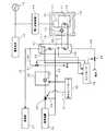
エンジン11は発電機12の運転に伴って熱を発生し、この熱はエンジン11の水冷装置16で熱交換により回収される。この熱回収はエンジン11のマフラー等の高温部分全てを対象とすることが好ましい。水冷装置16を通過する管路18内の冷却水はポンプ19で循環され、この冷却水を媒体として貯湯タンク17に熱量が運搬される。貯湯タンク17には管路18に接続された第1熱交換器20が設けられ、図示しない水供給源から貯湯タンク17に供給された水はこの第1熱交換器20からの熱で温水に加熱される。貯湯タンク17に蓄えられた温水は、第1の温水経路33を通じて第1熱負荷としての給湯器21に供給されて利用される。貯湯タンク17内には、貯湯タンク17内の水の温度を検出する水温センサ36と、貯湯タンク内17の水の量を検出する水位センサ37とが設けられる。 The engine 11 generates heat with the operation of the
ポンプ19はエンジン発電機10の運転に連動して起動する一方、エンジン発電機10が停止されると、その時点から予定時間(タイマによって設定される)経過後に停止するようにするのがよい。ポンプ19は、エンジン11側の温度が貯湯タンク17側より高くなった時に起動してもよいし、気温が低いときにはエンジン11を貯湯タンク17の温水で暖めるために始動に先行して起動してもよい。 While the
図示しない水供給源と貯湯タンク17との間には給水管38が設けられ、給水管38には給水バルブ39が設けられる。給水バルブ39は、貯湯タンク17内の水量が基準値以下になったときに開かれて給水を可能にする。 A
第1の温水経路33は、排水管40に分岐する。排水管40の途中には、排水バルブ41が設けられ、この排水バルブ41は、通常のメンテナンスのときに排水のために開放されるほか、強制的に熱需要を発生させる特別な措置として排水のために開放される。 The first
第1熱交換器20の上方には第2熱交換器22が設けられる。第2熱交換器22には、第1の温水経路33とは独立した第2の温水経路23が接続される。第2の温水経路23にはセントラルヒーティングシステムや床暖房システム等、第2熱負荷としての暖房装置24が設けられ、第2熱交換器22から出た温水が暖房装置24を通って貯湯タンク17内の第2熱交換器22に戻る循環路を形成する。第2の温水経路23によって、貯湯タンク17から2次的に熱を回収することができる。 A
第2熱交換器22を第1熱交換器20よりも上方の位置に配置したのは、第1熱交換器20から熱量を得た温度の高い水が、対流によって第1熱交換器20よりも上方に移動しているためである。第1熱交換器20よりも第2熱交換器22を上方に配置することにより、対流して上方に移動した高温の温水から多くの熱量を取出すことができる。 The reason why the
第2の温水経路23には追い焚きボイラ25と三方弁26とが設けられている。追い焚きボイラ25には第2の温水経路23内で温水を循環させるためのポンプ27が設けられている。また、第2の温水経路23を管路28側に切り換えて温水をバイパスさせて暖房装置24への温水の給送を停止させるための切り替え手段三方弁26が設けられる。 The second
コントローラ29は熱需要に応じてエンジン11の始動および停止の制御を行う。すなわち、コントローラ29は、水温センサ36によって検出された水温Tが予め設定された設定温度T1以下のときにエンジン11を駆動して熱量を発生させる。 The
エンジン発電機10の連続運転で得られる熱量を熱消費量が超えたような場合や、システムの立上げ時には、貯湯タンク17内の温水の温度は低下し、給水された水の温度が熱需要に応じられる温度になっていないことがある。貯湯タンク17内の温水の温度をエンジン発電機10からの回収熱のみでは基準温度に維持できないときに、温水コントローラ30で追い焚きボイラ25を運転する。温水コントローラ30は、水温センサ36によって検出された水温Tが水温T2(T1>T2)以下になったときに、追い焚きボイラ25に追い焚き指令Bを出力すると共に、三方弁26に切替指令Cを出力する。切替指令Cがオンのとき三方弁26は温水が管路28に流れるように切り替えられる。 When the heat consumption exceeds the amount of heat obtained by continuous operation of the
本実施形態では、停電発生等の非常時には、熱需要がない場合にも電力需要に応えられるように特別の措置として強制的に熱需要を発生させ、エンジン発電機10を運転できるようにする。熱需要がない場合にもエンジン発電機10を運転できるようにするコントローラ29の機能を説明する。図1において、熱要求発生部42は、水温Tが温度T1以下になったとき、つまり熱需要があるときに熱要求信号を出力する。熱需要がない場合には、強制的に熱需要を発生させて熱要求発生部42から熱要求信号を発生させる。熱要求発生部42から出力される熱要求信号に従ってエンジン11が駆動される。 In the present embodiment, in the event of an emergency such as a power outage, the
強制的な熱需要の発生手段は次のように構成できる。水温Tが設定温度T1以下にならないと熱要求発生部42は熱要求信号を出力しない。そこで、熱需要を発生させるために、水温Tを設定温度T1以下に低下させる。例えば、第1給水指示部43を設けることができる。第1給水指示部43は、水温Tが設定温度T1以上のときに給水指令を給水バルブ39に入力して給水バルブ39を開くように制御する。給水バルブ39が開かれると貯湯タンク17に外部から冷水が給水されて水温Tが低下する。水温Tが設定水温T1以下に低下すると、熱要求発生部41は、入力される水温値によって熱需要が形成されたことを認識して熱要求信号を出力し、エンジン11が起動される。 The means for generating forced heat demand can be configured as follows. If the water temperature T is not lower than the set temperature T1, the heat request generator 42 does not output a heat request signal. Therefore, in order to generate the heat demand, the water temperature T is lowered to the set temperature T1 or lower. For example, the 1st water supply instruction | indication part 43 can be provided. The 1st water supply instruction | indication part 43 inputs a water supply command into the
また、次のようにして熱需要を発生させることができる。例えば、排水指示部44を設けることができる。排水指示部44は、水温Tが設定温度T1以上になったときに排水指令を排水バルブ41に入力して排水バルブ41を開くように制御する。排水バルブ41が開かれると貯湯タンク17の温水は貯湯タンク17外へ排水されて水位Lが低下する。第2給水指示部45は、貯湯タンク17内の水位Lが予め設定されて水位L1以下になると給水指令を給水バルブ39に入力して給水バルブ39を開く。給水バルブ39が開かれると貯湯タンク17に給水されて水温Tが低下する。これによって、熱需要が形成され、熱要求発生部41が熱要求信号を出力してエンジン11が起動される。 Moreover, a heat demand can be generated as follows. For example, a drainage instruction unit 44 can be provided. The drainage instruction unit 44 controls to open the
上述の機能により、貯湯タンク内の水温や水位に基づいて強制的に熱需要が発生されるようにして自動的に単独運転可能にしているので、冷蔵庫やコンピュータ等、継続して電源を供給する必要がある電気負荷に好適な熱需要優先型コジェネレーション装置を提供することができる。 With the above-mentioned function, the heat demand is forcibly generated based on the water temperature and water level in the hot water storage tank so that it can be automatically operated independently. It is possible to provide a heat demand priority type cogeneration apparatus suitable for a necessary electrical load.
強制的に熱需要を発生させる機能は、系統の停電時等非常時に電力需要を賄うために必要となることが想定される。したがって、停電検出器46を設けて、この停電検出器46で停電が検出されたときにのみ、第1給水部43または排水指示部45が動作するように構成できる。 It is assumed that the function to forcibly generate heat demand is necessary to cover power demand in the event of an emergency such as a power failure. Therefore, the power failure detector 46 can be provided, and the first water supply unit 43 or the drainage instruction unit 45 can be operated only when a power failure is detected by the power failure detector 46.
また、強制的に熱需要を発生させる機能は、選択可能な機能としてもよい。例えば、通行の動作モードとは別に、強制的に熱需要を発生させて電力需要に応える自立運転モードを選択可能な選択スイッチ47を設ける。そして、この選択スイッチ47が自立運転モードに切り替えられたときに、第1給水部43または排水指示部45が動作するように構成できる。 Further, the function for forcibly generating the heat demand may be a selectable function. For example, a selection switch 47 capable of selecting a self-sustaining operation mode that compulsorily generates heat demand and responds to power demand is provided separately from the operation mode of traffic. When the selection switch 47 is switched to the self-sustaining operation mode, the first water supply unit 43 or the drainage instruction unit 45 can be configured to operate.
停電検出器46は、周知のものを使用することができる。例えば、停電は系統14の移送の跳躍の有無によって判断できる。商用電力系統14の停電時や異常時には、連系スイッチを制御して系統14からエンジン発電機10を解列する。停電検出や異常検出、ならびに商用電力系統から解列に関しては、例えば、特開2002−70606号公報に記載した技術を使用することができる。 A known power failure detector 46 can be used. For example, a power failure can be determined by the presence or absence of a jump in the transfer of the
図3は、コントローラ29の要部動作の一例を示すフローチャートである。同図において、ステップS1では、エンジン発電機10の運転開始指示がなされたか否かが判別される。運転開始指示があれば、ステップS2に進んで、水温Tが設定水温T1以下かどうかを判別する。水温Tが設定水温T1以下であれば、ステップS2Aに進んでエンジンが運転中か否かが判断され、運転中であれば、ステップS5に進み、運転中でなければ(停止していれば)、ステップS3に進んでエンジン11を始動させる。一方、水温Tが設定水温T1以下でなければ、ステップS4に進んで給水バルブ39を開き、貯湯タンク17に給水する。給水バルブ39を開いたならば、ステップS2に進む。給水によって水温Tが設定水温T1以下になれば、ステップS2は肯定になり、ステップS3でエンジン11が始動される。つまり、エンジン発電機10は、水温Tのいかんにかかわらず、運転開始指示がなされれば、エンジン11の始動が可能な状態になる。 FIG. 3 is a flowchart showing an example of the operation of the main part of the
ステップS5では、給水バルブ39を開く指令をオフにする。このオフ指令によって、給水バルブ39が開いていれば閉じられるし、閉じているときには給水バルブ39は現状に維持される。ステップS6では、運転停止指示の有無を判別する。運転停止指示があればステップS7に進んで、エンジン11に停止指示を与えてエンジン11を停止する。運転停止指示がなければ、ステップS8に進んで水温Tが設定水温T1以下かどうかを判別する。水温Tが設定水温T1以下でなければ、ステップS4に進む。 In step S5, the command to open the
図4,図5は、コントローラ29の要部動作の他の例を示すフローチャートである。図4は、貯湯タンク17の給水制御に係るフローチャートである。ステップS10は、貯湯タンク17内の水位Lが設定水位L1以下のときは、ステップS11に進んで給水バルブ39を開くための指令をオンにする。一方、貯湯タンク内17の水位Lが設定水位L1以下でないときは、ステップS12に進んで給水バルブ39を開くための指令をオフにする。こうして、貯湯タンク17の設定水位を維持するように給水バルブ39が制御される。 4 and 5 are flowcharts showing other examples of the operation of the main part of the
図4の処理に加えて図5の処理を行うことにより貯湯タンク17内の水温Tが設定水温T1になり、強制的に熱需要が形成されてエンジン発電機10の運転が可能になる。 By performing the process of FIG. 5 in addition to the process of FIG. 4, the water temperature T in the hot
図5において、ステップS21では、エンジン発電機10の運転開始指示がなされたか否かが判別される。運転開始指示があれば、ステップS22に進んで、水温Tが設定水温T1以下かどうかを判別する。水温Tが設定水温T1以下であれば、ステップS22Aに進んでエンジンが運転中か否かが判断され、運転中であれば、ステップS25に進み、運転中でなければ(停止していれば)、ステップS23に進んでエンジン11を始動させる。 In FIG. 5, in step S21, it is determined whether or not an instruction to start operation of the
一方、水温Tが設定水温T1以下でなければ、ステップS24に進んで排水バルブ41を開き、貯湯タンク17から排水する。排水バルブ41を開いたならば、ステップS22に進む。排水によって水位Lが設定水位L1以下に下がれば、図4の処理によって給水バルブ39が開かれる。 On the other hand, if the water temperature T is not lower than the set water temperature T1, the process proceeds to step S24, the
この給水により、水温Tが設定水温T1以下になれば、ステップS22は肯定になり、ステップS23でエンジン11が始動される。つまり、エンジン発電機10は、水温Tのいかんにかかわらず、運転開始指示がなされれば、エンジン11の運転が可能な状態になる。 If the water temperature T becomes equal to or lower than the set water temperature T1 due to this water supply, step S22 becomes affirmative and the engine 11 is started in step S23. That is, the
ステップS25では、排水バルブ41を開く指令をオフにする。このオフ指令によって、排水バルブ41が開いていれば閉じられるし、閉じているときには排水バルブ41は現状に維持される。ステップS26では、運転停止指示の有無を判別する。運転停止指示があればステップS27に進んで、エンジン11に停止指示を与えてエンジン11を停止する。運転停止指示がなければ、ステップS28に進んで水温Tが設定水温T1以下かどうかを判別する。水温Tが設定水温T1以下でなければ、ステップS24に進む。 In step S25, the command to open the
図4に示した水位維持制御は、使用された水量を補給するために給湯設備には通常用いられる。また、排水バルブも、貯湯タンク17のような設備には通常に設けられる。したがって、この実施形態では、既存の設備を制御して、熱需要がないときに熱需要を発生させてエンジン発電機10を運転可能とすることができる。例えば、商用電力系統14が停電のときには、この系統14から発電機12は解列されるとともに、前記停電検出器46で停電が検出されて熱需要を強制的に発生させる特別な措置が施されるので、必要な電力需要に応えることができる。 The water level maintenance control shown in FIG. 4 is normally used in a hot water supply facility in order to replenish the amount of water used. Also, a drain valve is usually provided in equipment such as the hot
10…エンジン発電機、 11…エンジン、 12…発電機、 13…電力変換装置、 14…商用電力系統、 17…貯湯タンク、 20…第1熱交換器、 21…給湯器、 22…第2熱交換器、 24…暖房装置、 29…コントローラ、 36…水温センサ、 37…水位センサ、 39…給水バルブ、 41…排水バルブ、 DESCRIPTION OF
Claims (5)
Translated fromJapanese前記水温センサで検出された水温が設定温度以上のときに前記貯湯タンク内の水温を低下させる手段を具備したことを特徴とするコジェネレーション装置。An engine, a generator driven by the engine, a heat exchanger for recovering exhaust heat of the engine and heating the water in the hot water storage tank with the exhaust heat, and a water temperature for detecting the water temperature in the hot water storage tank In a heat demand priority type cogeneration apparatus that has a sensor and controls the engine to be operable when the water temperature is equal to or lower than a set temperature,
A cogeneration apparatus comprising means for lowering the water temperature in the hot water storage tank when the water temperature detected by the water temperature sensor is equal to or higher than a set temperature.
前記貯湯タンク内の水温を低下させる手段が、前記貯湯タンクから排水して水位を前記設定レベル以下に下げる手段であることを特徴とする請求項1記載のコジェネレーション装置。Water supply means for supplying water to the hot water storage tank when the water level in the hot water storage tank falls below a set level;
2. The cogeneration apparatus according to claim 1, wherein the means for lowering the water temperature in the hot water storage tank is means for draining from the hot water storage tank and lowering the water level below the set level.
前記系統の停電を検出する停電検出手段を具備するとともに、
前記系統の停電時に前記水温を低下させる手段を作動させるように構成されていることを特徴とする請求項1〜3のいずれかに記載のコジェネレーション装置。The generator output is linked to the grid,
With a power failure detection means for detecting a power failure of the system,
The cogeneration apparatus according to any one of claims 1 to 3, wherein the cogeneration apparatus is configured to operate means for lowering the water temperature during a power failure of the system.
Priority Applications (4)
| Application Number | Priority Date | Filing Date | Title |
|---|---|---|---|
| JP2004266777AJP2006083720A (en) | 2004-09-14 | 2004-09-14 | Cogeneration equipment |
| US11/662,210US8172157B2 (en) | 2004-09-14 | 2005-08-30 | Cogeneration apparatus |
| PCT/JP2005/015717WO2006030629A1 (en) | 2004-09-14 | 2005-08-30 | Cogeneration apparatus |
| TW094131408ATWI368689B (en) | 2004-09-14 | 2005-09-13 | Cogeneration apparatus |
Applications Claiming Priority (1)
| Application Number | Priority Date | Filing Date | Title |
|---|---|---|---|
| JP2004266777AJP2006083720A (en) | 2004-09-14 | 2004-09-14 | Cogeneration equipment |
Publications (1)
| Publication Number | Publication Date |
|---|---|
| JP2006083720Atrue JP2006083720A (en) | 2006-03-30 |
Family
ID=36059884
Family Applications (1)
| Application Number | Title | Priority Date | Filing Date |
|---|---|---|---|
| JP2004266777APendingJP2006083720A (en) | 2004-09-14 | 2004-09-14 | Cogeneration equipment |
Country Status (4)
| Country | Link |
|---|---|
| US (1) | US8172157B2 (en) |
| JP (1) | JP2006083720A (en) |
| TW (1) | TWI368689B (en) |
| WO (1) | WO2006030629A1 (en) |
Cited By (5)
| Publication number | Priority date | Publication date | Assignee | Title |
|---|---|---|---|---|
| JP2009103418A (en)* | 2007-10-25 | 2009-05-14 | Honda Motor Co Ltd | Cogeneration system |
| JP2009191775A (en)* | 2008-02-15 | 2009-08-27 | Honda Motor Co Ltd | Cogeneration equipment |
| JP2009204239A (en)* | 2008-02-28 | 2009-09-10 | Noritz Corp | Cogeneration system |
| JP2015094577A (en)* | 2013-11-14 | 2015-05-18 | 大阪瓦斯株式会社 | Cogeneration system |
| JP2015534032A (en)* | 2012-09-28 | 2015-11-26 | キュンドン ナビエン カンパニー リミテッドKyungdong Navien Co.,Ltd. | Hot water temperature control structure of exhaust heat recovery system using three-way valve or mixing valve, and hot water temperature control structure of exhaust heat recovery system using hot water tank heat exchanger |
Families Citing this family (20)
| Publication number | Priority date | Publication date | Assignee | Title |
|---|---|---|---|---|
| JP2006083720A (en)* | 2004-09-14 | 2006-03-30 | Honda Motor Co Ltd | Cogeneration equipment |
| US20080236561A1 (en)* | 2007-03-26 | 2008-10-02 | Mr. Arthur Isaacs | Combination gas-fired furnace and gas-powered electrical generator |
| JP2009103112A (en)* | 2007-10-25 | 2009-05-14 | Honda Motor Co Ltd | Cogeneration system |
| GB0808930D0 (en)* | 2008-05-16 | 2008-06-25 | Sunamp Ltd | Energy Storage system |
| US8505498B2 (en)* | 2009-12-17 | 2013-08-13 | Advanced Conservation Technology Distribution, Inc. | Commercial hot water control system |
| JP5729910B2 (en)* | 2010-03-05 | 2015-06-03 | 三菱重工業株式会社 | Hot water heat pump and control method thereof |
| US9182159B2 (en)* | 2010-10-14 | 2015-11-10 | Purpose Company Limited | Water heater and control method therefor |
| US9915450B2 (en)* | 2012-03-15 | 2018-03-13 | Pas, Inc. | Multi-split heat pump for heating, cooling, and water heating |
| JP5845161B2 (en)* | 2012-10-16 | 2016-01-20 | 本田技研工業株式会社 | Cogeneration equipment |
| US9631547B2 (en)* | 2012-10-19 | 2017-04-25 | Ford Global Technologies, Llc | PHEV heating modes to provide cabin comfort |
| US9638413B2 (en) | 2014-03-05 | 2017-05-02 | Progreen Labs, Llc | Treatment device of a heating system |
| US9488373B2 (en) | 2014-03-06 | 2016-11-08 | Progreen Labs, Llc | Treatment device of a heating system |
| US9593857B2 (en) | 2014-03-07 | 2017-03-14 | ProGreen Labs, LLC. | Heating system |
| JP6452465B2 (en)* | 2015-01-20 | 2019-01-16 | 大阪瓦斯株式会社 | Heat supply system |
| KR102369684B1 (en) | 2017-05-02 | 2022-03-04 | 스파크 써미오닉스, 인크. | System and method for work function reduction and thermionic energy conversion |
| WO2019005678A1 (en)* | 2017-06-27 | 2019-01-03 | Imby Energy, Inc. | Cogeneration systems and methods for generating heating and electricity |
| US10699886B2 (en) | 2018-11-06 | 2020-06-30 | Spark Thermionics, Inc. | System and method for thermionic energy conversion |
| CA3165013A1 (en)* | 2020-02-07 | 2021-08-12 | Adam Lorimer | System and method for combined heat and electric power generation |
| CN115769339A (en) | 2020-05-06 | 2023-03-07 | 火花热离子学公司 | System and method for thermionic energy conversion |
| AU2022421994B2 (en) | 2021-12-21 | 2025-10-02 | Spark Thermionics, Inc. | Burner system and method of operation |
Family Cites Families (40)
| Publication number | Priority date | Publication date | Assignee | Title |
|---|---|---|---|---|
| US4339307A (en)* | 1977-01-21 | 1982-07-13 | Ellis Jr John C | Distillation apparatus |
| US4441902A (en)* | 1982-02-02 | 1984-04-10 | Kaman Sciences Corporation | Heat reclaiming method and apparatus |
| CA1182363A (en)* | 1982-11-03 | 1985-02-12 | Remo Rotili | Heating system using wood as the principal source of energy |
| CA1202928A (en)* | 1984-12-19 | 1986-04-08 | Man J. Wong | Water distiller |
| US4906337A (en)* | 1987-03-26 | 1990-03-06 | Palmer David G | Water supply system |
| US4715192A (en)* | 1987-06-15 | 1987-12-29 | Imperial Private Power | Electrical or thermal tracking cogeneration system utilizing open cycle-air-conditioning |
| US4861435A (en)* | 1988-01-25 | 1989-08-29 | Sweet Jr Herbert F | Water distillation apparatus for under-the-sink operation |
| US4857755A (en)* | 1988-09-27 | 1989-08-15 | Comstock W Kenneth | Constant power system and method |
| US5617504A (en)* | 1992-06-03 | 1997-04-01 | Sciacca; Thomas | Cogeneration system and control therefor with auxiliary heating elements and thermal barrier |
| US5517822A (en)* | 1993-06-15 | 1996-05-21 | Applied Energy Systems Of Oklahoma, Inc. | Mobile congeneration apparatus including inventive valve and boiler |
| US5392741A (en)* | 1993-12-17 | 1995-02-28 | General Motors Corporation | Locomotive engine cooling system |
| US5607013A (en)* | 1994-01-27 | 1997-03-04 | Takenaka Corporation | Cogeneration system |
| JPH09195738A (en)* | 1996-01-18 | 1997-07-29 | Komatsu Ltd | ENGINE VALVE MECHANISM CONTROL DEVICE AND ITS CONTROL METHOD |
| JP3804693B2 (en) | 1996-06-21 | 2006-08-02 | 大阪瓦斯株式会社 | Waste heat recovery system |
| DE19720881A1 (en)* | 1997-05-17 | 1998-11-19 | Asea Brown Boveri | Combined heat and power station with conversion turbines |
| JPH11117739A (en)* | 1997-10-09 | 1999-04-27 | Toyota Motor Corp | Cooling water circulation device for internal combustion engine |
| US6234400B1 (en)* | 1998-01-14 | 2001-05-22 | Yankee Scientific, Inc. | Small scale cogeneration system for producing heat and electrical power |
| US6053418A (en)* | 1998-01-14 | 2000-04-25 | Yankee Scientific, Inc. | Small-scale cogeneration system for producing heat and electrical power |
| JP3890765B2 (en) | 1998-09-09 | 2007-03-07 | 本田技研工業株式会社 | Cogeneration equipment |
| US6073857A (en)* | 1998-09-14 | 2000-06-13 | Fairlane Tool Company | Co-generator utilizing micro gas turbine engine |
| JP2000205044A (en)* | 1999-01-19 | 2000-07-25 | Shigeaki Kimura | Cogeneration system |
| JP2000297963A (en) | 1999-04-14 | 2000-10-24 | Honda Motor Co Ltd | Cogeneration equipment |
| JP3620701B2 (en)* | 1999-04-14 | 2005-02-16 | 本田技研工業株式会社 | Cogeneration equipment |
| JP3767785B2 (en)* | 1999-10-22 | 2006-04-19 | 本田技研工業株式会社 | Engine exhaust heat recovery device |
| JP2001123886A (en)* | 1999-10-25 | 2001-05-08 | Hitachi Ltd | Electric power / hot water supply equipment |
| JP2001132539A (en)* | 1999-11-01 | 2001-05-15 | Honda Motor Co Ltd | Engine exhaust heat recovery device |
| JP3631107B2 (en)* | 2000-06-09 | 2005-03-23 | 株式会社日本製鋼所 | Cogeneration system using micro gas turbine waste heat gas |
| JP3804755B2 (en) | 2000-08-28 | 2006-08-02 | 本田技研工業株式会社 | Engine power generator and cogeneration system |
| JP4423440B2 (en) | 2001-03-12 | 2010-03-03 | 株式会社ノーリツ | Heat recovery system |
| AUPR418901A0 (en)* | 2001-04-04 | 2001-05-03 | Applidyne Pty Ltd | Control system for cogeneration unit |
| JP2003120211A (en) | 2001-10-05 | 2003-04-23 | Kawasaki Heavy Ind Ltd | Gas turbine device with heat exchanger for boiler |
| JP3742356B2 (en)* | 2002-03-20 | 2006-02-01 | 株式会社日立製作所 | Heat pump water heater |
| JP3894892B2 (en) | 2003-01-30 | 2007-03-22 | 東京瓦斯株式会社 | Cogeneration apparatus and control method thereof |
| US6959876B2 (en)* | 2003-04-25 | 2005-11-01 | Honeywell International Inc. | Method and apparatus for safety switch |
| JP2006083720A (en)* | 2004-09-14 | 2006-03-30 | Honda Motor Co Ltd | Cogeneration equipment |
| KR100702039B1 (en)* | 2004-12-10 | 2007-03-30 | 엘지전자 주식회사 | Cogeneration System |
| KR101270614B1 (en)* | 2006-07-25 | 2013-06-07 | 엘지전자 주식회사 | Co-generation |
| KR101270616B1 (en)* | 2006-07-27 | 2013-06-07 | 엘지전자 주식회사 | Cogeneration |
| JP2009103112A (en)* | 2007-10-25 | 2009-05-14 | Honda Motor Co Ltd | Cogeneration system |
| JP5011062B2 (en)* | 2007-10-25 | 2012-08-29 | 本田技研工業株式会社 | Cogeneration system |
- 2004
- 2004-09-14JPJP2004266777Apatent/JP2006083720A/enactivePending
- 2005
- 2005-08-30USUS11/662,210patent/US8172157B2/ennot_activeExpired - Fee Related
- 2005-08-30WOPCT/JP2005/015717patent/WO2006030629A1/enactiveApplication Filing
- 2005-09-13TWTW094131408Apatent/TWI368689B/ennot_activeIP Right Cessation
Cited By (5)
| Publication number | Priority date | Publication date | Assignee | Title |
|---|---|---|---|---|
| JP2009103418A (en)* | 2007-10-25 | 2009-05-14 | Honda Motor Co Ltd | Cogeneration system |
| JP2009191775A (en)* | 2008-02-15 | 2009-08-27 | Honda Motor Co Ltd | Cogeneration equipment |
| JP2009204239A (en)* | 2008-02-28 | 2009-09-10 | Noritz Corp | Cogeneration system |
| JP2015534032A (en)* | 2012-09-28 | 2015-11-26 | キュンドン ナビエン カンパニー リミテッドKyungdong Navien Co.,Ltd. | Hot water temperature control structure of exhaust heat recovery system using three-way valve or mixing valve, and hot water temperature control structure of exhaust heat recovery system using hot water tank heat exchanger |
| JP2015094577A (en)* | 2013-11-14 | 2015-05-18 | 大阪瓦斯株式会社 | Cogeneration system |
Also Published As
| Publication number | Publication date |
|---|---|
| TW200622095A (en) | 2006-07-01 |
| WO2006030629A1 (en) | 2006-03-23 |
| US20080061158A1 (en) | 2008-03-13 |
| TWI368689B (en) | 2012-07-21 |
| US8172157B2 (en) | 2012-05-08 |
Similar Documents
| Publication | Publication Date | Title |
|---|---|---|
| JP2006083720A (en) | Cogeneration equipment | |
| JP3676660B2 (en) | Engine power generator | |
| JP4854549B2 (en) | Combined heat and power system | |
| JP2009284590A (en) | Power generation system | |
| JP3724634B2 (en) | Engine power generator and cogeneration system | |
| JP2015065009A (en) | Cogeneration apparatus | |
| JP2011185520A (en) | Cogeneration system | |
| JP2008057854A (en) | Cogeneration system | |
| JP2004053120A (en) | Cogeneration system | |
| JP5381084B2 (en) | Cogeneration system and hot water storage system | |
| JP5809844B2 (en) | FUEL CELL POWER GENERATION SYSTEM AND METHOD FOR POWERING UP ELECTRIC HEATER IN FUEL CELL POWER GENERATION SYSTEM | |
| JP4913095B2 (en) | Combined heat and power system | |
| JP2000297963A (en) | Cogeneration equipment | |
| JP3804755B2 (en) | Engine power generator and cogeneration system | |
| JP4606895B2 (en) | Cogeneration equipment | |
| JP2007248008A (en) | Cogeneration system and operation method thereof | |
| JP6551062B2 (en) | Cogeneration system | |
| JP5245807B2 (en) | Cogeneration system and hot water storage system | |
| JPH08226145A (en) | Heat insulation device for piped water in hot water supply system | |
| JP2015025586A (en) | Cogeneration device | |
| JP2008121936A (en) | Cogeneration system | |
| JP2016031025A (en) | Cogeneration system | |
| JP2006084056A (en) | Cogeneration equipment | |
| JP4360495B2 (en) | Cogeneration equipment | |
| JP4134923B2 (en) | Hot water supply device |
Legal Events
| Date | Code | Title | Description |
|---|---|---|---|
| A621 | Written request for application examination | Free format text:JAPANESE INTERMEDIATE CODE: A621 Effective date:20061130 | |
| A131 | Notification of reasons for refusal | Free format text:JAPANESE INTERMEDIATE CODE: A131 Effective date:20080702 | |
| A02 | Decision of refusal | Free format text:JAPANESE INTERMEDIATE CODE: A02 Effective date:20081105 |