JP2006082186A - Article supply device - Google Patents
Article supply deviceDownload PDFInfo
- Publication number
- JP2006082186A JP2006082186AJP2004270171AJP2004270171AJP2006082186AJP 2006082186 AJP2006082186 AJP 2006082186AJP 2004270171 AJP2004270171 AJP 2004270171AJP 2004270171 AJP2004270171 AJP 2004270171AJP 2006082186 AJP2006082186 AJP 2006082186A
- Authority
- JP
- Japan
- Prior art keywords
- article
- articles
- robot
- visual sensor
- supply apparatus
- Prior art date
- Legal status (The legal status is an assumption and is not a legal conclusion. Google has not performed a legal analysis and makes no representation as to the accuracy of the status listed.)
- Granted
Links
- 230000000007visual effectEffects0.000claimsabstractdescription42
- 238000001514detection methodMethods0.000claimsabstractdescription33
- 238000005192partitionMethods0.000claimsdescription36
- 239000006185dispersionSubstances0.000claimsdescription10
- 238000000638solvent extractionMethods0.000claims2
- 230000004308accommodationEffects0.000abstractdescription8
- 230000002411adverseEffects0.000abstractdescription4
- 238000000034methodMethods0.000description18
- 238000003780insertionMethods0.000description8
- 230000037431insertionEffects0.000description8
- 230000010485copingEffects0.000description3
- 239000011347resinSubstances0.000description3
- 229920005989resinPolymers0.000description3
- 238000000605extractionMethods0.000description2
- 230000004044responseEffects0.000description2
- 230000002159abnormal effectEffects0.000description1
- 230000002093peripheral effectEffects0.000description1
Images


Classifications
- B—PERFORMING OPERATIONS; TRANSPORTING
- B65—CONVEYING; PACKING; STORING; HANDLING THIN OR FILAMENTARY MATERIAL
- B65G—TRANSPORT OR STORAGE DEVICES, e.g. CONVEYORS FOR LOADING OR TIPPING, SHOP CONVEYOR SYSTEMS OR PNEUMATIC TUBE CONVEYORS
- B65G47/00—Article or material-handling devices associated with conveyors; Methods employing such devices
- B65G47/02—Devices for feeding articles or materials to conveyors
- B65G47/04—Devices for feeding articles or materials to conveyors for feeding articles
- B65G47/12—Devices for feeding articles or materials to conveyors for feeding articles from disorderly-arranged article piles or from loose assemblages of articles
- B65G47/14—Devices for feeding articles or materials to conveyors for feeding articles from disorderly-arranged article piles or from loose assemblages of articles arranging or orientating the articles by mechanical or pneumatic means during feeding
- B65G47/1407—Devices for feeding articles or materials to conveyors for feeding articles from disorderly-arranged article piles or from loose assemblages of articles arranging or orientating the articles by mechanical or pneumatic means during feeding the articles being fed from a container, e.g. a bowl
- B65G47/1442—Devices for feeding articles or materials to conveyors for feeding articles from disorderly-arranged article piles or from loose assemblages of articles arranging or orientating the articles by mechanical or pneumatic means during feeding the articles being fed from a container, e.g. a bowl by means of movement of the bottom or a part of the wall of the container
- B65G47/1457—Rotating movement in the plane of the rotating part
- B—PERFORMING OPERATIONS; TRANSPORTING
- B65—CONVEYING; PACKING; STORING; HANDLING THIN OR FILAMENTARY MATERIAL
- B65G—TRANSPORT OR STORAGE DEVICES, e.g. CONVEYORS FOR LOADING OR TIPPING, SHOP CONVEYOR SYSTEMS OR PNEUMATIC TUBE CONVEYORS
- B65G47/00—Article or material-handling devices associated with conveyors; Methods employing such devices
- B65G47/02—Devices for feeding articles or materials to conveyors
- B65G47/04—Devices for feeding articles or materials to conveyors for feeding articles
- B65G47/12—Devices for feeding articles or materials to conveyors for feeding articles from disorderly-arranged article piles or from loose assemblages of articles
- B65G47/14—Devices for feeding articles or materials to conveyors for feeding articles from disorderly-arranged article piles or from loose assemblages of articles arranging or orientating the articles by mechanical or pneumatic means during feeding
- B65G47/1407—Devices for feeding articles or materials to conveyors for feeding articles from disorderly-arranged article piles or from loose assemblages of articles arranging or orientating the articles by mechanical or pneumatic means during feeding the articles being fed from a container, e.g. a bowl
- B65G47/1442—Devices for feeding articles or materials to conveyors for feeding articles from disorderly-arranged article piles or from loose assemblages of articles arranging or orientating the articles by mechanical or pneumatic means during feeding the articles being fed from a container, e.g. a bowl by means of movement of the bottom or a part of the wall of the container
- B65G47/1471—Movement in one direction, substantially outwards
Landscapes
- Engineering & Computer Science (AREA)
- Mechanical Engineering (AREA)
- Manipulator (AREA)
- Specific Conveyance Elements (AREA)
- Stacking Of Articles And Auxiliary Devices (AREA)
Abstract
Translated fromJapaneseDescription
Translated fromJapanese本発明は物品供給装置に関し、更に詳しく言えば、多数の物品を適度に分散させた上で、視覚センサ−ロボットシステムで取扱い、供給先に供給するに適した物品供給装置に関する。 The present invention relates to an article supply apparatus, and more particularly, to an article supply apparatus suitable for handling a large number of articles with a visual sensor-robot system and supplying them to a supply destination after appropriate dispersion.
例えば組立工場などでは、多数の物品をロボットで1個ずつ把持し、次の供給先に供給する工程は極く一般的なものとなっている。その場合、ロボットにより把持が行われる箇所への搬入をどうするかがシステムの効率、経済性、信頼性、などを左右する有力なファクターである。従来、ロボットによる把持が行なわれる箇所への物品の搬入は、機械的なパーツフィーダで行なわれることが多く、また、把持対象の物品の位置(又は位置と姿勢)を2次元視覚センサあるいは3次元視覚センサで検出してロボット動作を補正する手法も繁用されている。 For example, in an assembly factory or the like, a process of holding a large number of articles one by one with a robot and supplying them to the next supplier is very common. In that case, how to carry in the place where the robot is gripped is an important factor that determines the efficiency, economy, reliability, and the like of the system. Conventionally, an article is often carried into a place where a robot is gripped by a mechanical parts feeder, and the position (or position and orientation) of the object to be gripped is determined by a two-dimensional visual sensor or a three-dimensional sensor. A technique of correcting the robot motion by detecting with a visual sensor is also frequently used.
しかし、そのようなシステムにおいて、効率等の観点から一度に多数の物品を搬入する場合、ロボットによる把持を容易にするためには、断続的な振動により物品の分散(物品同士が重なり合った状態を解消すること)、整列を行なう必要があったため、物品に振動による損傷を与える恐れがあった。また、搬入される物品は、サイズ、形状等の異なる複数種類にわたることが多く、それら種類毎に専用の調整を施した装置が必要であった。
そこで、ロボットによる把持が行われる箇所へ一度に多数の物品を搬入しても、簡便な構成で、物品に振動により悪影響を与えることなく物品を分散し、視覚センサによる認識/検出とそれに基づくロボットによる把持が容易且つ確実に行えるようにした物品供給装置の開発が望まれているが、公知文献にその例を見いだせない。However, in such a system, when a large number of articles are carried in at a time from the viewpoint of efficiency and the like, in order to facilitate gripping by the robot, the dispersion of the articles by intermittent vibration (the state where the articles overlap each other) Since it was necessary to perform alignment, there was a risk of damage to the article due to vibration. In addition, articles to be carried in often include a plurality of types having different sizes, shapes, and the like, and a device with dedicated adjustment for each type is required.
Therefore, even if a large number of articles are carried into a place where the robot is gripped at a time, the articles are distributed with a simple configuration without adversely affecting the articles due to vibration, and recognition / detection by a visual sensor and a robot based thereon Although it is desired to develop an article supply apparatus that can be easily and reliably gripped by the above-mentioned method, no example can be found in known literature.
本発明の基本的な目的は、上記従来技術の問題点を解消することにある。即ち、本発明は、ロボットに把持が行われる箇所へ一度に多数の物品を搬入しても、簡便な構成で、物品に振動により悪影響を与えることなく物品を分散し、視覚センサによる認識/検出とそれに基づくロボットによる把持が容易且つ確実に行えるようにした物品供給装置を提供しようとするものである。また、これと併せて本発明は、複数種類の物品供給を1台で行なうことが可能な供給装置を提供することを企図している。 The basic object of the present invention is to eliminate the above-mentioned problems of the prior art. That is, according to the present invention, even if a large number of articles are carried into a place where the robot is gripped at a time, the articles are distributed with a simple structure without adversely affecting the articles due to vibration, and recognition / detection by a visual sensor. And an article supply device that can be easily and reliably gripped by a robot based on the above. In addition, the present invention contemplates providing a supply apparatus capable of supplying a plurality of types of articles with a single unit.
更に別の観点から言えば、本発明は、単純な運動のみで機能を果たす構造を有する物品供給装置、多数の物品を貯留、格納する機能を持ち、長時間連続運転が容易な物品供給装置を実現しようとするものでもある。 From another point of view, the present invention provides an article supply apparatus having a structure that performs a function only by simple movement, and an article supply apparatus that has a function of storing and storing a large number of articles and that can be operated continuously for a long time. It is also something that is going to be realized.
本発明は、テーブルと相対運動する仕切り・くぐり抜け部材を使用して、簡便な構造で、振動原理によらない物品の分散を可能にし、同相対運動により同仕切り・くぐり抜け部材をくぐり抜けた分散物品の位置(又は位置と姿勢)を視覚センサで認識し、同検出結果に基づいてロボットを動作させて、把持を確実に行なわせるようにすることで、上記目的を達成するものである。 The present invention uses a partition / passing member that moves relative to the table, and enables the dispersion of articles that do not depend on the vibration principle with a simple structure, and the distributed article that passes through the partition / passing member by the relative motion. The above object is achieved by recognizing the position (or position and posture) with a visual sensor and operating the robot based on the detection result to ensure gripping.
より具体的に言えば、本発明は、複数の物品を載置する載置面を有するテーブルと、該載置面上の複数の物品を分散する物品分散手段とを含む物品分散装置と、該分散された物品毎に位置、又は位置と姿勢を検出する視覚センサと、該検出された物品毎の位置又は位置と姿勢とに基いて、該物品を1個ずつ把持して供給先に供給するロボットとを備えた物品供給装置に係るものである。 More specifically, the present invention relates to an article dispersion apparatus including a table having a placement surface for placing a plurality of articles, and article dispersion means for dispersing the plurality of articles on the placement surface, Based on a visual sensor that detects the position or position and orientation of each dispersed article and the detected position or position and orientation of each article, the articles are gripped one by one and supplied to the supply destination. The present invention relates to an article supply apparatus including a robot.
そして、請求項1に記載された発明の特徴に従えば、前記物品分散手段は、前記テーブルとの間で相対運動が可能であり、且つ、前記載置面との間に所定距離の間隙を形成するとともに、前記載置面上方の空間を前記複数の物品が搬入される第1の側の領域と、前記相対運動によって前記空隙をくぐり抜けた物品について前記ロボットによる把持が行なわれる第2の側の領域とに区分する仕切り・くぐり抜け部材と、前記仕切り・くぐり抜け部材に前記相対運動を行なわせるための駆動手段と、前記相対運動の内容が教示された教示プログラムと該教示プログラムに基いて前記駆動手段を制御する制御手段とを備えている。 According to the feature of the invention described in
ここで、前記制御手段を前記ロボットの制御装置が兼ねること(請求項2)、前記駆動手段を前記ロボットが兼ねること(請求項3)のいずれも可能である。
また、前記テーブル上に同時に複数種類の物品が搬入され、前記視覚センサにより物品毎の位置又は位置と姿勢を検出すると共に該物品の種類を識別し、前記ロボットが該識別された種類に応じた供給先に前記物品を供給するようにすることもできる(請求項4)。Here, it is possible that either the control unit of the robot also serves as the control unit (Claim 2) or the robot also serves as the drive unit (Claim 3).
Further, a plurality of types of articles are simultaneously carried on the table, the position or position and posture of each article is detected by the visual sensor, the type of the article is identified, and the robot responds to the identified type. The article may be supplied to a supply destination (claim 4).
更に、前記相対運動のための教示プログラムを複数記憶し、前記視覚センサによる検出結果が、前記ロボットによる把持を行なう上で不適切であることを意味するものである場合に、前記検出結果に関する情報に応じて、該複数の教示プログラムの中から実行する教示プログラムを選択可能とすることができる(請求項5)。 In addition, when a plurality of teaching programs for the relative motion are stored and the detection result by the visual sensor means that it is inappropriate for gripping by the robot, information on the detection result Accordingly, it is possible to select a teaching program to be executed from among the plurality of teaching programs.
そして、前記第1の側の領域に対応して上方が開放された物品格納空間を設け、該物品格納空間は、前記仕切り・くぐり抜け部材と、前記載置面から所定高さまでの空間の一部を側部囲み部材で取り囲まれた空間とすることもできる。 An article storage space that is open upward is provided corresponding to the first side area, and the article storage space includes the partition / passing member and a part of the space from the placement surface to a predetermined height. Can be a space surrounded by a side enclosing member.
なお、仕切り・くぐり抜け部材のテーブルに対する前記相対運動を、回転運動として、教示プログラムにより第1の回転方向の回転運動と該第1の回転方向と逆の第2の回転方向の回転運動とを交互に繰返し実行するようにしても良いし(請求項7)、あるいは、直線運動とし、教示プログラムにより、第1の方向の直線運動と、該第1の方向と逆の第2の方向の直線運動を交互に繰返し実行するようにしても良い(請求項8)。また、これらいずれの発明の諸態様においても、前記視覚センサとして2次元視覚センサ又は3次元視覚センサを適宜用いることができる。 The relative motion of the partition / passing member with respect to the table is a rotational motion, and the rotational motion in the first rotational direction and the rotational motion in the second rotational direction opposite to the first rotational direction are alternately performed by the teaching program. (Claim 7) or a linear motion, and a linear motion in a first direction and a linear motion in a second direction opposite to the first direction by a teaching program. May be repeatedly executed alternately (claim 8). In any of these aspects of the invention, a two-dimensional visual sensor or a three-dimensional visual sensor can be appropriately used as the visual sensor.
本発明により、ロボットによる把持が行われる箇所へ一度に多数の物品を搬入しても、物品に振動により悪影響を与えることなく物品を分散し、視覚センサによる認識/検出とそれに基づくロボットによる把持が容易且つ確実に行えるようにした、簡便な構成の物品供給装置が提供される。また、本発明によれば、複数種類の物品供給を1台で行なうことが可能な物品供給装置が提供される。更に、本発明に係る物品供給装置は、単純な運動のみで物品分散とロボットへの受渡し機能を果たす構造を有するという特徴も有している。また、仕切り・くぐり抜け部材と併用される側部囲み部材を利用して、物品の貯留、格納能力を拡充することが容易な、長時間連続運転に適した物品供給装置を実現するものでもある。 According to the present invention, even if a large number of articles are carried into a place where the robot is gripped at once, the articles are dispersed without adversely affecting the articles, and recognition / detection by the visual sensor and gripping by the robot based on the recognition are possible. An article supply apparatus having a simple configuration that can be easily and reliably performed is provided. In addition, according to the present invention, an article supply apparatus capable of supplying a plurality of types of articles with a single unit is provided. Furthermore, the article supply apparatus according to the present invention also has a feature that it has a structure that performs an article distribution and a delivery function to a robot only by a simple motion. Moreover, the article | item supply apparatus suitable for long-time continuous operation which is easy to expand the storage and storage capability of articles | goods is also implement | achieved using the side part surrounding member used together with a partition and a passing-through member.
以下、図面を参照して本発明のいくつかの実施形態について説明する。先ず図1は、本発明の第1の実施形態の外観図であり、物品分散装置専用のテーブル駆動手段を持つ事例を示す。同図において、物品分散装置全体は符号1で示されており、同物品分散装置1に搬入された物品を把持して次の供給先(図示省略)へ運ぶロボット全体は符号20で示されている。物品分散装置1は基台2を有し、基台2上に駆動モータ3で回転駆動される回転テーブル4が設置されており、その上面が物品を載置する載置面5を提供している。 Hereinafter, some embodiments of the present invention will be described with reference to the drawings. First, FIG. 1 is an external view of a first embodiment of the present invention, and shows an example having table driving means dedicated to an article distribution apparatus. In the figure, the entire article dispersing apparatus is indicated by
符号6は回転テーブル4の載置面5の上方空間をほぼ等分するように設けられた仕切り・くぐり抜け部材で、取付け支持部材8を介して基台2に固定されている。物品分散装置1への物品搬入は、この仕切り・くぐり抜け部材6を境にしてロボット20から遠い側(図1の例では左側)に対して行なわれる。この物品搬入側には、仕切り・くぐり抜け部材6と併せて物品を収容して貯留できる物品収容空間を形成するための囲み部材10が、仕切り・くぐり抜け部材6と同じく、取付け支持部材8を用いて設けられている。本例では、囲み部材10はU字状の枠状部材で、物品収容空間の内部が見え易いように透明な樹脂板でできている。
仕切り・くぐり抜け部材6は、その下縁7が載置面5の間に所定の大きさ(距離)の空隙9を形成するように設けられている。ここで、空隙9の大きさ(距離)は、物品収容空間に搬入された多数の物品が回転テーブル4の回転に従って少しずつくぐり抜け、図示されているように分散した状態となるような値に設計的に定められる。物品分散装置1に搬入される物品は、サイズに余り大きな相違がない限り、複数種類(品種)であっても構わない。ここでは、円柱形状の物品Wa と直方体形状の物品Wb が区別なく多数物品収容空間に搬入される例が示されている。なお、物品の搬入法に特に制限はなく、前段工程のコンベア、ハンドリングロボットなどが用いられて良く、人手による搬入であっても良い。 The partition / pass-through
回転テーブル4を回転駆動する駆動モータ3は、ロボット制御装置30に接続されており、その制御内容は、ロボット制御装置30内に用意される教示プログラム(1つまたは複数)によって定められる。詳細は後述するが、駆動モータ3の正回転/逆回転の切替や、回転角度、回転速度の制御等が可能である。従って、回転テーブル4は、ロボット制御装置30が指令に応じて、テーブル上方から見て時計周り、反時計周りのいずれにも回転し得る(両矢印Aを参照)。 The drive motor 3 that rotationally drives the rotary table 4 is connected to the
今、図示されているように、物品分散装置1の物品収容空間に円柱形状の物品Wa と直方体形状の物品Wb が多数搬入されている状態で回転テーブル4が時計周りあるいは反時計周りに回転すると、物品収容空間内(仕切り・くぐり抜け部材6の左側)に互いに重なり合って収容、貯留されている物品Wa 、Wb が少しずつ(例えば1個ずつ)仕切り・くぐり抜け部材6をくぐり抜けて、仕切り・くぐり抜け部材6の右側に逃れ出て来る。 As shown in the drawing, when the rotary table 4 rotates clockwise or counterclockwise in a state where a large number of cylindrical articles Wa and rectangular parallelepiped articles Wb are carried into the article storage space of the
符号40はこの逃れ出て来た物品を検出する2次元視覚センサあるいは3次元視覚センサの検出ヘッドで、典型的にはCCDカメラあるいはCCDカメラとパター光投光器の組み合わせが用いられる。検出ヘッド40は、ロボット制御装置30に接続されており、その制御及び検出ヘッド40で得られた情報(画像情報)の処理、解析、記憶等はロボット制御装置30で行なわれる。なお、このように、検出ヘッド40はロボット制御装置30を用いて、物品の形状、位置、姿勢等を検出する2次元視覚センサあるいは3次元視覚センサを構成することや、形状、位置、姿勢等の検出手法自体は周知技術に属するので、詳細説明は省略する。
ロボット20はアーム先端部にハンド21を装着したもので、その開閉動作は、ロボット制御装置30によって周知の態様で制御される。視覚センサによって物品Wa または物品Wb が1つ以上認識・検出されると、その内の1つ(次のロボット動作で把持する物品)について、位置(または位置と姿勢)が求められる。ロボット制御装置30は、それに基づいて補正されるロボット動作(取出し動作)を実行し、1つの物品Wa または物品Wb を把持して次の供給先に搬送する。視覚センサによる物品の検出結果がロボットによる取出し動作にとって不適切である場合(例えば検出できず等)の対処法については後述する。 The
以上述べた第1実施形態では、物品分散装置専用のテーブル駆動手段(モータ3)を用いているが、ロボットにテーブル駆動手段を兼ねさせることも可能である。その事例を図2に第2実施形態として示した。同図において、物品分散装置全体は符号50で示されており、同物品分散装置50に搬入された物品を把持して次の供給先(図示省略)へ運ぶロボット全体は符号20で示されている。物品分散装置50は基台51を有し、基台51上に回転テーブル52が設置されており、その上面が物品を載置する載置面53を提供している。 In the first embodiment described above, the table driving means (motor 3) dedicated to the article distribution apparatus is used, but it is also possible for the robot to also serve as the table driving means. An example of this is shown in FIG. 2 as a second embodiment. In the same figure, the entire article dispersing apparatus is indicated by
符号6は、第1の実施形態と同様の態様で、回転テーブル52の載置面53の上方空間をほぼ等分するように設けられた仕切り・くぐり抜け部材で、取付け支持部材8を介して基台51に固定されている。物品分散装置50への物品搬入は、この仕切り・くぐり抜け部材6を境にしてロボット20から遠い側(図2において左側)に対して行なわれる。また、この物品搬入側には、第1の実施形態と同じく、仕切り・くぐり抜け部材6と併せて物品を収容して貯留できる物品収容空間を形成するための囲み部材10が、取付け支持部材8を用いて設けられている。囲み部材10はU字状の枠状部材で、物品収容空間の内部が見え易いように透明な樹脂板でできている。
仕切り・くぐり抜け部材6は、その下縁7が載置面53の間に所定の大きさ(距離)の空隙9を形成するように設けられている。空隙9の大きさ(距離)の定め方は、第1の実施形態の場合と同様である。 The partition / passing through
即ち、物品収容空間に搬入された多数の物品が回転テーブル52の回転に従って少しずつくぐり抜け、図示されているように分散した状態となるような値に設計的に定められる。本実施形態においても、物品分散装置50に搬入される物品は、サイズに余り大きな相違がない限り、複数種類(品種)であっても構わない。図2には、円柱形状の物品Wa と直方体形状の物品Wb が多数物品収容空間に搬入される例が示されている。既述の通り、物品の搬入法に特に制限はない。 That is, the value is designed in such a manner that a large number of articles carried into the article storage space pass through little by little as the rotary table 52 rotates and are dispersed as shown. Also in the present embodiment, the articles carried into the
回転テーブル52の回転駆動は、ロボット20によって行なわれる。そのために、回転テーブル52の周縁部の適所(1箇所以上)に回転用ロボットジョイントが設けられ、回転用ロボットジョイント54に係合可能な係合部材55が使用される。ロボット20は、第1実施形態と同じくアーム先端にハンド21を装着したものであるが、ハンド21は物品Wa 、Wb の把持に用いられるだけでなく、回転テーブル52の回転駆動時に係合部材55を掴むためにも兼用される。 The rotary table 52 is rotationally driven by the
回転用ロボットジョイント54と係合部材55の組み合わせには種々に形態があり得るが、ここでは開口部を持つ回転用ロボットジョイント54と同開口部に差込み係合される差込みロッドの組み合わせの例が示されている。差込みロッド55は1本以上用意され、ロボット20が回転テーブル52の回転駆動を行なおうとする時及び回転駆動中以外には、仕切り・くぐり抜け部材6の右側(ロボット側)に位置した回転用ロボットジョイント54の開口部に差し込まれた状態で保持される。回転テーブル52が不用意に回転しないように、回転テーブル52には回転ロックブレーキ56が付設されており、ロボット制御装置30によってロックとその解除が行えるようになっている。回転ロックブレーキ56は、回転テーブル52の回転駆動の直前から直後までの期間以外は、ロックされた状態とされる。 The combination of the rotation robot joint 54 and the
ロボット20が回転テーブル52の回転駆動を行なおうとする時には、差込みロッド55の位置を視覚センサで検出し、それに基づいてロボット20を動作させ、差込みロッド55をハンド21で掴み、回転ロックブレーキ56のロックを解除してから、回転テーブル52を回転させる。必要な回転動作を終えたら、回転ロックブレーキ56をロック状態に戻し、差込みロッド55を離す。回転角度が大きい場合には、差込みロッド55を別の回転用ロボットジョイント54に差し込む動作を交える場合もあり得る。 When the
これらテーブルの回転駆動についてのロボット動作の制御内容は、ロボット制御装置30内に用意される教示プログラム(1つまたは複数)によって定められている。このようなロボット20を利用した回転駆動によっても、回転テーブル52の正回転/逆回転の選択や、回転角度、回転速度の制御等が可能なことは言うまでもない(両矢印Bを参照)。 The control content of the robot operation regarding the rotational drive of these tables is determined by the teaching program (one or more) prepared in the
今、図示されているように、物品分散装置50の物品収容空間に円柱形状の物品Wa と直方体形状の物品Wb が多数搬入されている状態で、ハンド21が差込みロッド55を掴み、回転テーブル52を時計周りあるいは反時計周りに回転させたとすると、物品収容空間内(仕切り・くぐり抜け部材6の左側)に互いに重なり合って収容、貯留されている物品Wa 、Wb が少しずつ(例えば1個ずつ)仕切り・くぐり抜け部材6をくぐり抜けて、仕切り・くぐり抜け部材6の右側に逃れ出て来る。 As shown in the drawing, in the state where a large number of cylindrical articles Wa and rectangular parallelepiped articles Wb are carried into the article storage space of the
ハンド21が差込みロッド55を離した後、検出ヘッド40とロボット制御装置30で構成される2次元視覚センサあるいは3次元視覚センサで物品Wa または物品Wb が1つ以上認識・検出されると、その内の1つ(次のロボット動作で把持する物品)について、位置(または位置と姿勢)が求められる。ロボット制御装置30は、それに基づいて補正されるロボット動作(取出し動作)を実行し、1つの物品Wa または物品Wb を把持して次の供給先に搬送する。視覚センサによる物品の検出結果がロボットによる取出し動作にとって不適切である場合(例えば検出できず等)の対処法については後述する。 When one or more articles Wa or articles Wb are recognized and detected by the two-dimensional visual sensor or the three-dimensional visual sensor constituted by the
以上、第1、第2実施形態で説明したように、本発明では回転テーブルと仕切り・くぐり抜け部材の組み合わせで、多数の搬入物品を少しずつ分散した状態で視覚センサの検出ヘッドの視野内で送り出すことができるが、回転テーブルに代えて前進及び後退の直線運動を行なうテーブルと仕切り・くぐり抜け部材の組み合わせを採用することもできる。その事例を図3に第3実施形態として示した。 As described above in the first and second embodiments, in the present invention, a combination of a rotary table and a partition / pass-through member is used to send a large number of articles to be delivered within the field of view of the detection head of the visual sensor while being gradually dispersed. However, instead of the rotary table, a combination of a table that performs forward and backward linear motion and a partition / passing member may be employed. An example of this is shown in FIG. 3 as a third embodiment.
同図において、物品分散装置全体は符号60で示されており、同物品分散装置60に搬入された物品を把持して次の供給先(図示省略)へ運ぶロボット全体は符号20で示されている。物品分散装置60は基台61を有し、基台61上にコンベアテーブル62が設置されており、その上面が物品を載置する載置面63を提供している。 In the figure, the entire article dispersing apparatus is indicated by
符号6は、第1、第2の実施形態と類似した態様で、コンベアテーブル62の載置面63の上方空間を二分するように設けられた仕切り・くぐり抜け部材で、取付け支持部材8を介して基台61に固定されている。物品分散装置60への物品搬入は、この仕切り・くぐり抜け部材6を境にしてロボット20から遠い側(図3において左側)に対して行なわれる。また、この物品搬入側には、第1及び第2の実施形態と類似した態様で、仕切り・くぐり抜け部材6と協働して物品を収容・貯留できる物品収容空間を形成するための囲み部材65が、取付け支持部材8を用いて設けられている。囲み部材65は略コの字状の枠状部材で、物品収容空間の内部が見え易いように透明な樹脂板でできている。
仕切り・くぐり抜け部材6は、その下縁7が載置面63の間に所定の大きさ(距離)の空隙を形成するように設けられている。空隙9の大きさ(距離)の定め方は、第1あるいは第2の実施形態の場合と類似している。 The partition / passing through
即ち、コンベアテーブル62が前進運動(ロボット20側へ向かう運動)を行なった時、物品収容空間に搬入された多数の物品がその空隙を少しずつくぐり抜け、図示されているように分散した状態となるような値が設計的に定められる。なお、本実施形態では、物品収容空間でない側の物品載置領域にも、物品がコンベアテーブル62からこぼれ落ちないように、低い高さを持つ枠部材66が追加されている。取付け支持部材8は、この枠部材66の取付け、支持にも利用できる。 That is, when the conveyor table 62 performs a forward movement (movement toward the
本実施形態においても、物品分散装置60に搬入される物品は、サイズに余り大きな相違がない限り、複数種類(品種)であっても構わない。図3には、円柱形状の物品Wa と直方体形状の物品Wb が多数物品収容空間に搬入される例が示されている。既述の通り、物品の搬入法に特に制限はない。
コンベアテーブル62の駆動は、専用のモータ64によって行なわれる。モータ64は、ロボット制御装置30に接続されており、その制御内容は、ロボット制御装置30内に用意される教示プログラム(1つまたは複数)によって定められる。駆動モータ64の正回転/逆回転の切替や、回転角度、回転速度の制御等が可能であり、従って、コンベアテーブル62は、ロボット制御装置30が指令に応じて、ロボット20に接近する前進運動と離隔する後退運動(両矢印Cを参照)を行なうことができる。Also in this embodiment, the articles carried into the
The conveyor table 62 is driven by a
今、図示されているように、物品分散装置60の物品収容空間に円柱形状の物品Wa と直方体形状の物品Wb が多数搬入されている状態でコンベアテーブル62が前進運動を行なうと、物品収容空間内(仕切り・くぐり抜け部材6の左側)に互いに重なり合って収容、貯留されている物品Wa 、Wb が少しずつ(例えば1個ずつ)仕切り・くぐり抜け部材6をくぐり抜けて、仕切り・くぐり抜け部材6の右側に逃れ出て来る。 As shown in the figure, when the conveyor table 62 moves forward in a state where a large number of cylindrical articles Wa and rectangular parallelepiped articles Wb are carried into the article storage space of the
検出ヘッド40とロボット制御装置30で構成される2次元視覚センサあるいは3次元視覚センサで物品Wa または物品Wb が1つ以上認識・検出されると、その内の1つ(次のロボット動作で把持する物品)について、位置(または位置と姿勢)が求められる。ロボット制御装置30は、それに基づいて補正されるロボット動作(取出し動作)を実行し、1つの物品Wa または物品Wb を把持して次の供給先に搬送する。視覚センサによる物品の検出結果がロボットによる取出し動作にとって不適切である場合(例えば検出できず等)の対処法については後述する。 When one or more articles Wa or articles Wb are recognized and detected by the two-dimensional visual sensor or the three-dimensional visual sensor constituted by the
次に、図4は本発明の物品供給装置で実行される制御フローチャート(取出し動作1回分)を例示したもので、例えば上述した各実施形態において実行される。処理の開始は、上述した各実施形態で、物品収容空間に1バッチ分の多数の物品搬入が行なわれたことを表わす外部信号を受けて開始されるものとする。なお、この外部信号には物品供給装置の前段側のシステムが正常である限り、どのような品種の物品(複数品種の組み合わせ、または1品種)が搬入されたかを表わす物品品種情報が、ロボット制御装置30に予め登録されたコードデータで含まれているものとする。 Next, FIG. 4 exemplifies a control flowchart (for one take-out operation) executed by the article supply apparatus of the present invention, and is executed in each of the above-described embodiments, for example. The processing is started in response to an external signal indicating that a large number of articles for one batch have been carried into the article storage space in each of the above-described embodiments. In this external signal, as long as the system on the front side of the article supply apparatus is normal, the article type information indicating what kind of article (a combination of plural kinds or one kind) has been carried in is controlled by the robot. It is assumed that it is included in code data registered in the
先ず、物品品種情報に基づいて、検出プログラムを選択する(S1)。検出プログラムは、視覚センサで物品を認識し、品種、位置(または位置及び姿勢)を検出する動作、処理を定めたもので、ここでは3種類(S2〜S4)が例示されている。今、物品の品種として上記実施形態で述べた円柱形状の物品Wa 、直方体形状の物品Wb に加えて、円錐形状の物品(Wc と表記)を考えた場合、例えばS2の検出プログラムはWa とWb の組み合わせで搬入がなされる場合、S3の検出プログラムはWb とWc の組み合わせで搬入がなされる場合、S4の検出プログラムはWc とWa の組み合わせで搬入がなされる場合に選択されるものである。 First, a detection program is selected based on the product type information (S1). The detection program defines an operation and a process for recognizing an article with a visual sensor and detecting a product type and position (or position and orientation), and three types (S2 to S4) are exemplified here. Now, in addition to the columnar article Wa and the rectangular parallelepiped article Wb described in the above embodiment, the detection program of S2 is, for example, the detection program Wa and Wb. The detection program of S3 is selected when the combination of Wb and Wc is used, and the detection program of S4 is selected when the combination of Wc and Wa is used.
先ず、物品品種情報に基づいて、検出プログラムが選択される(S1)。検出プログラムは、視覚センサで物品を認識し、品種、位置(または位置及び姿勢)を検出する動作、処理を定めたもので、ここでは3種類(S2〜S4)が例示されている。今、物品の品種として上記実施形態で述べた円柱形状の物品Wa 、直方体形状の物品Wb に加えて、円錐形状の物品(Wc と表記)を考えた場合、例えばS2の検出プログラムはWa とWb の組み合わせで搬入がなされる場合、S3の検出プログラムはWb とWc の組み合わせで搬入がなされる場合、S4の検出プログラムはWc とWa の組み合わせで搬入がなされる場合に選択されるものである。なお、物品品種情報が見いだせない場合は異常アラームを出力した上でS1へ戻り、物品品種情報が見いだせる外部信号の入力を待つ(S5)。 First, a detection program is selected based on the product type information (S1). The detection program defines an operation and a process for recognizing an article with a visual sensor and detecting a product type and position (or position and orientation), and three types (S2 to S4) are exemplified here. Now, in addition to the columnar article Wa and the rectangular parallelepiped article Wb described in the above embodiment, the detection program of S2 is, for example, the detection program Wa and Wb. The detection program of S3 is selected when the combination of Wb and Wc is used, and the detection program of S4 is selected when the combination of Wc and Wa is used. If the article type information cannot be found, an abnormal alarm is output and the process returns to S1 to wait for an external signal to be found for the article type information (S5).
選択された検出プログラムが実行し、検出結果に応じて後続の処理を選択する(S6)。例えば上述した第1〜第3の実施形態で、視覚センサの検出ヘッド40の視野内に分散した物品が存在し、物品の認識、品種、位置(または位置及び姿勢)の正常な検出(物品が把持可能な状態で検出)に成功した場合には、ロボット20による取出し動作を実行する(S7)。 The selected detection program is executed, and a subsequent process is selected according to the detection result (S6). For example, in the first to third embodiments described above, there are articles dispersed in the visual field of the
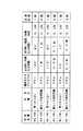
もし、物品の認識、品種、位置(または位置及び姿勢)の正常な検出(物品が把持可能な状態で検出)が行えなかった場合には、ロボット20による取出し動作には移らず、品種(品種情報で判断)と状況に応じて予め教示しておいた複数のプログラム(分散状況、品種別、分散動作プログラム)から、プログラムを1つ選択して実行する。複数のプログラムは、フローチャートでは3種類(S8〜S10)が例示されているが、それ以上のプログラムが用意されることも多い。このプログラムは、具体的には、物品の品種及び状況に応じて、視覚センサによる物品の検出が正常に行えるように物品を検出ヘッド40の視野内にもって来るための動作を物品分散装置1(または50、60)に行なわせる動作を選択するもので、そこで定められる動作の一例を表形式で図5に示した。 If the normal recognition of the article, the kind, and the position (or position and orientation) cannot be detected (detected while the article can be gripped), the picking operation by the
物品の品種としては、上記の例に対応して、Wa (円柱形状)とWb (直方体形状)の組み合わせ、Wb (直方体形状)とWc (円錐形状)の組み合わせ及びWc (円錐形状)とWa (円柱形状)の組み合わせを想定する。また、状況の種別としては、「物品が見つからない」と、「物品同士が重なり合って把持困難」の2種類を想定する。この場合、例えば計6種類のプログラム(分散状況、品種別、分散動作プログラム)が用意される。これらをPR1〜PR6で表中に示した。 Corresponding to the above example, the product types are combinations of Wa (cylindrical shape) and Wb (cuboid shape), Wb (cuboid shape) and Wc (conical shape), and Wc (conical shape) and Wa (conical shape). (Cylinder shape) combination is assumed. In addition, two types of situations are assumed: “the article cannot be found” and “the article is overlapped and difficult to hold”. In this case, for example, a total of six types of programs (distributed status, product type, distributed operation program) are prepared. These are shown in the table as PR1 to PR6.
例えばPR1は、Wa (円柱形状)とWb (直方体形状)の組み合わせのケースで、物品が検出ヘッド40の視野内(仕切り・くぐり抜け部材6の右側領域)に見つからない場合に選択されるプログラムで、「回転テーブルの180度正回転」→「回転テーブルの90度逆回転」→「0.5秒待機」のサイクルを1回実行するものである。
また、PR4は、Wb (直方体形状)とWc (円錐形状)の組み合わせのケースで、物品が検出ヘッド40の視野内(仕切り・くぐり抜け部材6の右側領域)で見つかるが重なり合って把持困難な場合に選択されるプログラムで、「回転テーブルを0.5秒間正回転」→「回転テーブルを0.5秒間逆回転」→「0.2秒待機」のサイクルを5回実行するものである。For example, PR1 is a combination of Wa (cylindrical shape) and Wb (cuboid shape), and is a program that is selected when an article is not found in the field of view of the detection head 40 (the right side area of the partition / passing through member 6). A cycle of “180 degree forward rotation of the rotary table” → “90 degree reverse rotation of the rotary table” → “standby for 0.5 seconds” is executed once.
PR4 is a combination of Wb (cuboid shape) and Wc (conical shape). When an article is found in the field of view of the detection head 40 (the right side area of the partition / passing through member 6), it is difficult to grip it due to overlapping. In the selected program, a cycle of “rotating table is rotated forward for 0.5 seconds” → “rotating table is rotated backward for 0.5 seconds” → “waiting for 0.2 seconds” is executed five times.
なお、ここでは回転テーブル(第1実施形態における回転テーブル4または第2実施形態における回転テーブル52)を使用した物品分散装置の採用を想定したが、直線運動を行なうテーブルを用いた物品分散装置を採用するケースでも、正回転を「前進」、逆回転を「後退」として同様に各種プログラムを用意することができる。 Here, it is assumed that an article dispersing apparatus using a rotating table (the rotating table 4 in the first embodiment or the rotating table 52 in the second embodiment) is used, but an article dispersing apparatus using a table that performs linear motion is used. Even in the case of adopting the program, various programs can be prepared in the same manner with forward rotation as “forward” and reverse rotation as “backward”.
このように、品種、状況別に選択されたプログラムの実行(S11)後は、ステップS1へ戻り、再度検出を試みる。検出プログラムを選択して(S2〜S4)、検出に成功すれば、取出し動作を行なう(S7)。再度正常な検出ができなかった場合は、再度、品種・状況別の分散動作プログラムを選択して実行する(S11)。以下、同様の処理を繰り返す。なお、フローチャートには記載していないが、品種・状況別の分散動作プログラムの繰り返し実行回数に上限を設け、それを超えてもS7(取出し動作)へ進めなかった場合には、アラームを出力してシステムを停止させるようにしても良い。 As described above, after the execution of the program selected for each product type and situation (S11), the process returns to step S1 to try detection again. When a detection program is selected (S2 to S4) and the detection is successful, an extraction operation is performed (S7). If normal detection cannot be performed again, a distributed operation program for each type / situation is again selected and executed (S11). Thereafter, the same processing is repeated. Although not described in the flow chart, an upper limit is set on the number of repeated executions of the distributed operation program for each product type / situation. To stop the system.
1、50、60 物品分散装置
2、51、61 基台
3、64 駆動モータ
4、52 回転テーブル
5、53、63 載置面
6 仕切り・くぐり抜け部材
7 仕切り・くぐり抜け部材の下縁
8 取付け支持部材
9 空隙
10、65 囲み部材
20 ロボット
21 ハンド
30 ロボット制御装置
40 視覚センサの検出ヘッド
54 回転用ロボットジョイント
55 差込みロッド(係合部材)
56 回転ロックブレーキ
62 コンベアテーブル
66 枠部材
Wa 物品(円柱形状)
Wb 物品(直方体形状)
Wc 物品(円錐形状)DESCRIPTION OF
56
Wb article (rectangular shape)
Wc article (conical shape)
Claims (9)
Translated fromJapanese該分散された物品毎に位置、又は位置と姿勢を検出する視覚センサと、
該検出された物品毎の位置又は位置と姿勢とに基いて、該物品を1個ずつ把持して供給先に供給するロボットとを備えた物品供給装置において、
前記物品分散手段は、前記テーブルとの間で相対運動が可能であり、且つ、前記載置面との間に所定距離の間隙を形成するとともに、前記載置面上方の空間を前記複数の物品が搬入される第1の側の領域と、前記相対運動によって前記空隙をくぐり抜けた物品について前記ロボットによる把持が行なわれる第2の側の領域とに区分する仕切り・くぐり抜け部材と、
前記仕切り・くぐり抜け部材に前記相対運動を行なわせるための駆動手段と、
前記相対運動の内容が教示された教示プログラムと、
該教示プログラムに基いて前記駆動手段を制御する制御手段とを備えることを特徴とする、物品供給装置。An article dispersion apparatus including a table having a placement surface on which a plurality of articles are placed, and article dispersion means for dispersing the plurality of articles on the placement surface;
A visual sensor for detecting the position or position and posture of each dispersed article;
An article supply apparatus comprising: a robot that grips the articles one by one and supplies them to a supply destination based on the detected position or position and posture of each article;
The article dispersing means is capable of relative movement with the table, forms a gap of a predetermined distance from the placement surface, and allows the plurality of articles to pass through the space above the placement surface. A partitioning / passing member that divides the first side area into which the robot is carried and the second side area in which the robot grips the article that has passed through the gap by the relative motion;
Drive means for causing the partition / passing member to perform the relative movement;
A teaching program in which the contents of the relative motion are taught;
An article supply apparatus comprising: control means for controlling the drive means based on the teaching program.
該物品格納空間は、前記仕切り・くぐり抜け部材と、前記載置面から所定高さまでの空間の一部を側部囲み部材で取り囲まれた空間であることを特徴とする、請求項1乃至請求項5の内、何れか1項に記載の物品供給装置。There is provided an article storage space whose upper side is open corresponding to the region on the first side,
The article storage space is a space in which a part of the space from the partitioning surface and a predetermined height to the predetermined height is surrounded by a side enclosing member. The article supply apparatus according to any one of 5.
Priority Applications (4)
| Application Number | Priority Date | Filing Date | Title |
|---|---|---|---|
| JP2004270171AJP3876260B2 (en) | 2004-09-16 | 2004-09-16 | Article supply equipment |
| EP05020000AEP1642853A3 (en) | 2004-09-16 | 2005-09-14 | Handling robot system |
| CN200510103404.4ACN1749135A (en) | 2004-09-16 | 2005-09-15 | Handling robot system |
| US11/227,077US7580773B2 (en) | 2004-09-16 | 2005-09-16 | Handling robot system |
Applications Claiming Priority (1)
| Application Number | Priority Date | Filing Date | Title |
|---|---|---|---|
| JP2004270171AJP3876260B2 (en) | 2004-09-16 | 2004-09-16 | Article supply equipment |
Publications (2)
| Publication Number | Publication Date |
|---|---|
| JP2006082186Atrue JP2006082186A (en) | 2006-03-30 |
| JP3876260B2 JP3876260B2 (en) | 2007-01-31 |
Family
ID=35735257
Family Applications (1)
| Application Number | Title | Priority Date | Filing Date |
|---|---|---|---|
| JP2004270171AExpired - LifetimeJP3876260B2 (en) | 2004-09-16 | 2004-09-16 | Article supply equipment |
Country Status (4)
| Country | Link |
|---|---|
| US (1) | US7580773B2 (en) |
| EP (1) | EP1642853A3 (en) |
| JP (1) | JP3876260B2 (en) |
| CN (1) | CN1749135A (en) |
Cited By (12)
| Publication number | Priority date | Publication date | Assignee | Title |
|---|---|---|---|---|
| WO2008087702A1 (en)* | 2007-01-16 | 2008-07-24 | Hirata Corporation | Device and method for automatically assembling parts |
| JP2017014012A (en)* | 2015-07-02 | 2017-01-19 | オークラ輸送機株式会社 | Classification device |
| JP2017100237A (en)* | 2015-12-01 | 2017-06-08 | セイコーエプソン株式会社 | Robot system and robot |
| DE102017108327A1 (en) | 2016-04-26 | 2017-10-26 | Fanuc Corporation | Item allocation device |
| JP2018193201A (en)* | 2017-05-19 | 2018-12-06 | ファナック株式会社 | Supply control apparatus and supply control method |
| JP2019018974A (en)* | 2017-07-19 | 2019-02-07 | ファナック株式会社 | Feeder circulating workpiece, and carrier device comprising feeder |
| CN109928203A (en)* | 2019-03-26 | 2019-06-25 | 盐城工学院 | A kind of handling device of view-based access control model system |
| JP2019521053A (en)* | 2016-06-27 | 2019-07-25 | アマゾン テクノロジーズ インコーポレイテッド | Automatic item singulation including vibration table |
| US10518417B2 (en) | 2017-04-28 | 2019-12-31 | Fanuc Corporation | Article retrieval system |
| JP2020504673A (en)* | 2016-12-23 | 2020-02-13 | デ ビアス ユーケー リミテッド | Classification of gemstones |
| JP2021094682A (en)* | 2019-12-19 | 2021-06-24 | 矢崎総業株式会社 | Work-piece picking device |
| EP4313800A4 (en)* | 2021-07-29 | 2024-10-09 | Alp Havacilik Sanayi Ve Ticaret Anonim Sirketi | AUTOMATIC ORDER CLASSIFICATION AND TRANSFER MACHINE WITH ROBOT UNIT |
Families Citing this family (46)
| Publication number | Priority date | Publication date | Assignee | Title |
|---|---|---|---|---|
| WO2010024795A1 (en)* | 2008-08-29 | 2010-03-04 | Abb Research Ltd. | Robotic picking of parts from a bin using force feedback |
| IT1391349B1 (en)* | 2008-10-06 | 2011-12-13 | Ars S R L | POWER SUPPLY DEVICE FOR ROBOTS, AUTOMATION MEANS AND SIMILAR. |
| JP5549129B2 (en)* | 2009-07-06 | 2014-07-16 | セイコーエプソン株式会社 | Position control method, robot |
| EP2540456A1 (en) | 2009-08-27 | 2013-01-02 | ABB Research Ltd. | Robotic picking of parts from a parts holding bin |
| IT1395632B1 (en)* | 2009-09-14 | 2012-10-16 | Lanfranchi Srl | METHOD AND APPARATUS FOR TAKING AND TRANSFERRING THESE PREFORMATIONS COMING FROM TRANSPORT IN UNSOLIDED CONDITIONS |
| WO2011109041A1 (en)* | 2010-03-04 | 2011-09-09 | Mako Surgical Corp. | System with brake to limit manual movement of member and control system for same |
| DE202010007448U1 (en)* | 2010-06-01 | 2010-09-02 | Zbv-Automation Gmbh | separating device |
| DE102010063208A1 (en) | 2010-12-16 | 2012-06-21 | Robert Bosch Gmbh | Method for operating a safety device for a handling device, safety device for a handling device and handling device |
| JP5447483B2 (en)* | 2011-10-04 | 2014-03-19 | 株式会社安川電機 | Robot system and method of manufacturing workpiece |
| EP2839935A1 (en)* | 2012-04-19 | 2015-02-25 | Kabushiki Kaisha Yaskawa Denki | Robot system |
| JPWO2014013608A1 (en)* | 2012-07-20 | 2016-06-30 | 株式会社安川電機 | Robot system and article transfer method |
| DE102013013114A1 (en)* | 2012-08-17 | 2014-02-20 | Liebherr-Verzahntechnik Gmbh | Device for the automated removal of workpieces arranged in a container |
| EP2888187B1 (en)* | 2012-08-22 | 2016-08-03 | ABB Research Ltd. | A component feeder with flexible retaining walls |
| CN102825605B (en)* | 2012-09-13 | 2015-02-18 | 昆山市工业技术研究院有限责任公司 | Material delivering robot with visual detecting function |
| JP2014176923A (en)* | 2013-03-14 | 2014-09-25 | Yaskawa Electric Corp | Robot system and method for manufacturing workpiece |
| CN103303673A (en)* | 2013-05-21 | 2013-09-18 | 苏州惠瑞自动化集成有限公司 | Automated carrying mechanism |
| CN103496567B (en)* | 2013-10-18 | 2016-03-02 | 深圳市深立精机科技有限公司 | A kind of automatic charging device |
| CN104555352B (en)* | 2013-10-21 | 2017-04-12 | 泰科电子(上海)有限公司 | Automatic feed system |
| US9138895B2 (en)* | 2014-01-10 | 2015-09-22 | Recognition Robotics, Inc. | Method for picking up an article using a robot arm and associated system |
| CN103753531A (en)* | 2014-01-24 | 2014-04-30 | 成都万先自动化科技有限责任公司 | Company delivery service robot |
| CN103832810B (en)* | 2014-03-18 | 2017-04-12 | 苏州卓汇自动化设备有限公司 | Automatic feeding system with image recognition |
| CA2949813A1 (en)* | 2014-05-23 | 2015-11-26 | Intelligrated Headquarters Llc | Gapping systems and methods |
| CN104057459B (en)* | 2014-06-25 | 2017-02-22 | 上海发那科机器人有限公司 | Device and method for intelligently sorting workpieces by robot |
| CN104129624B (en)* | 2014-07-25 | 2016-12-07 | 姚将安 | The adjustable feeding device of medical apparatus and instruments kludge |
| JP6301782B2 (en)* | 2014-08-27 | 2018-03-28 | ファナック株式会社 | Article supply device that supplies articles by type |
| JP6392587B2 (en)* | 2014-08-27 | 2018-09-19 | ファナック株式会社 | Article supply device for supplying articles individually |
| CN104551513A (en)* | 2014-12-18 | 2015-04-29 | 广东大冶摩托车技术有限公司 | Island type automatic welding system |
| JP6456718B2 (en)* | 2015-02-19 | 2019-01-23 | 株式会社Fdkエンジニアリング | Spherical parts feeder |
| FR3043076B1 (en)* | 2015-11-02 | 2019-08-23 | Expertise Vision | INDIVIDUALIZATION DEVICE FOR LITTLE BULK OBJECTS |
| JP6527108B2 (en) | 2016-05-19 | 2019-06-05 | ファナック株式会社 | Article transport device |
| CN105858565A (en)* | 2016-06-01 | 2016-08-17 | 浙江万昇光电科技有限公司 | Intelligent LED (Light Emitting Diode) street lamp maintaining mechanical arm |
| CN105923348B (en)* | 2016-06-06 | 2018-06-08 | 珠海格力电器股份有限公司 | Unilateral moving type compressor identification and transportation system and transportation method thereof |
| JP2018034242A (en)* | 2016-08-31 | 2018-03-08 | セイコーエプソン株式会社 | Robot control device, robot, and robot system |
| CN106552772B (en) | 2016-10-25 | 2019-01-22 | 北京京东尚科信息技术有限公司 | Visual identifying system and the classification sorting system for using the visual identifying system |
| JP6450727B2 (en)* | 2016-10-28 | 2019-01-09 | ファナック株式会社 | Apparatus, method, program, and recording medium for simulating article alignment work performed by robot |
| CN108313784B (en)* | 2017-01-16 | 2019-10-11 | 泰科电子(上海)有限公司 | Diaphragm supply system and method |
| CN118305806A (en)* | 2017-06-06 | 2024-07-09 | 精工爱普生株式会社 | Control device and robot system |
| JP6496361B2 (en)* | 2017-07-20 | 2019-04-03 | ファナック株式会社 | Supply device for supplying workpiece to take-out device and transport device provided with supply device |
| CN107527115A (en)* | 2017-08-14 | 2017-12-29 | 震坤行工业超市(上海)有限公司 | Intelligent storage management method, device, system and unmanned intelligent storage equipment |
| EP3733567B1 (en)* | 2017-12-28 | 2025-02-05 | Itoh Denki Co., Ltd. | Cargo handling method |
| WO2020082176A1 (en)* | 2018-10-23 | 2020-04-30 | Waste Robotics Inc. | Robotic spearing device for performing item capture and sorting, spearing end effector and method for performing same |
| CN109731793A (en)* | 2018-12-17 | 2019-05-10 | 上海航天电子有限公司 | A kind of small lot chip bulk cargo device intelligent sorting equipment |
| ES1260666Y1 (en) | 2020-11-23 | 2021-12-28 | Posimat Sa | MACHINE FOR ORIENTATION AND ALIGNMENT OF BULK FED ARTICLES |
| DE102022102720A1 (en) | 2022-02-04 | 2023-08-10 | Henrik Klag | ROBOT CONTROLLED FEED DEVICE |
| CN115502100A (en)* | 2022-09-22 | 2022-12-23 | 深圳市诺泰芯装备有限公司 | A device and method for visually selecting and picking materials for wafers |
| EP4570713A1 (en)* | 2023-12-13 | 2025-06-18 | Kitopi One SPV Limited | A temporary storage table system |
Family Cites Families (11)
| Publication number | Priority date | Publication date | Assignee | Title |
|---|---|---|---|---|
| CH373246A (en)* | 1961-11-01 | 1963-11-15 | Participations Indufi Sa D | Vending machine |
| JPS56161213A (en)* | 1980-05-15 | 1981-12-11 | Hanai Seisakusho:Kk | Hopper-equipped rotary parts feeder |
| JPS61127514A (en)* | 1984-11-28 | 1986-06-14 | Hitachi Ltd | Recirculation type parts feeder |
| EP0544833B1 (en) | 1990-08-25 | 1996-10-16 | Intelligent Automation Systems, Inc. | Programmable reconfigurable parts feeder |
| US5272805A (en)* | 1991-04-01 | 1993-12-28 | Fanuc Robotics North America, Inc. | System for the flexible assembly of assemblies |
| US7481453B2 (en)* | 1991-07-09 | 2009-01-27 | Automotive Technologies International, Inc. | Inflator system |
| US7832762B2 (en)* | 1995-06-07 | 2010-11-16 | Automotive Technologies International, Inc. | Vehicular bus including crash sensor or occupant protection system control module |
| US7744122B2 (en)* | 1995-12-12 | 2010-06-29 | Automotive Technologies International, Inc. | Driver side aspirated airbags |
| DE19629314C1 (en) | 1996-07-20 | 1998-02-05 | Teves Gmbh Alfred | Device for separating and positioning flexible profile strips |
| JPH11300670A (en)* | 1998-04-21 | 1999-11-02 | Fanuc Ltd | Article picking-up device |
| CA2522097C (en)* | 2003-04-28 | 2012-09-25 | Stephen James Crampton | Cmm arm with exoskeleton |
- 2004
- 2004-09-16JPJP2004270171Apatent/JP3876260B2/ennot_activeExpired - Lifetime
- 2005
- 2005-09-14EPEP05020000Apatent/EP1642853A3/ennot_activeWithdrawn
- 2005-09-15CNCN200510103404.4Apatent/CN1749135A/enactivePending
- 2005-09-16USUS11/227,077patent/US7580773B2/enactiveActive
Cited By (19)
| Publication number | Priority date | Publication date | Assignee | Title |
|---|---|---|---|---|
| WO2008087702A1 (en)* | 2007-01-16 | 2008-07-24 | Hirata Corporation | Device and method for automatically assembling parts |
| JPWO2008087702A1 (en)* | 2007-01-16 | 2010-05-06 | 平田機工株式会社 | Automatic parts assembly apparatus and method |
| JP2017014012A (en)* | 2015-07-02 | 2017-01-19 | オークラ輸送機株式会社 | Classification device |
| JP2017100237A (en)* | 2015-12-01 | 2017-06-08 | セイコーエプソン株式会社 | Robot system and robot |
| DE102017108327B4 (en)* | 2016-04-26 | 2019-11-07 | Fanuc Corporation | Item allocation device |
| JP2017196685A (en)* | 2016-04-26 | 2017-11-02 | ファナック株式会社 | Article supply device |
| US9896273B2 (en) | 2016-04-26 | 2018-02-20 | Fanuc Corporation | Article supply apparatus |
| DE102017108327A1 (en) | 2016-04-26 | 2017-10-26 | Fanuc Corporation | Item allocation device |
| JP2019521053A (en)* | 2016-06-27 | 2019-07-25 | アマゾン テクノロジーズ インコーポレイテッド | Automatic item singulation including vibration table |
| JP2020504673A (en)* | 2016-12-23 | 2020-02-13 | デ ビアス ユーケー リミテッド | Classification of gemstones |
| US10518417B2 (en) | 2017-04-28 | 2019-12-31 | Fanuc Corporation | Article retrieval system |
| US10414600B2 (en) | 2017-05-19 | 2019-09-17 | Fanuc Corporation | Supply control device and supply control method |
| JP2018193201A (en)* | 2017-05-19 | 2018-12-06 | ファナック株式会社 | Supply control apparatus and supply control method |
| JP2019018974A (en)* | 2017-07-19 | 2019-02-07 | ファナック株式会社 | Feeder circulating workpiece, and carrier device comprising feeder |
| US10654169B2 (en) | 2017-07-19 | 2020-05-19 | Fanuc Corporation | Supply device configured to circulate workpieces and transport device equipped with supply device |
| CN109928203A (en)* | 2019-03-26 | 2019-06-25 | 盐城工学院 | A kind of handling device of view-based access control model system |
| JP2021094682A (en)* | 2019-12-19 | 2021-06-24 | 矢崎総業株式会社 | Work-piece picking device |
| JP7431031B2 (en) | 2019-12-19 | 2024-02-14 | 矢崎総業株式会社 | work picking device |
| EP4313800A4 (en)* | 2021-07-29 | 2024-10-09 | Alp Havacilik Sanayi Ve Ticaret Anonim Sirketi | AUTOMATIC ORDER CLASSIFICATION AND TRANSFER MACHINE WITH ROBOT UNIT |
Also Published As
| Publication number | Publication date |
|---|---|
| CN1749135A (en) | 2006-03-22 |
| EP1642853A2 (en) | 2006-04-05 |
| EP1642853A3 (en) | 2008-03-19 |
| US7580773B2 (en) | 2009-08-25 |
| JP3876260B2 (en) | 2007-01-31 |
| US20060057239A1 (en) | 2006-03-16 |
Similar Documents
| Publication | Publication Date | Title |
|---|---|---|
| JP3876260B2 (en) | Article supply equipment | |
| JP6805465B2 (en) | Box positioning, separation, and picking using sensor-guided robots | |
| US9132553B2 (en) | Robot system and method for producing a to-be-processed material | |
| JP6702909B2 (en) | Robot system | |
| CN104627643B (en) | Component feed system | |
| JP7027030B2 (en) | Picking hand and picking transfer device | |
| JP2017100214A (en) | Manipulator system, imaging system, object delivery method, and manipulator control program | |
| US11247304B2 (en) | Workpiece information recognition system | |
| JP2011115930A (en) | Robot device, workpiece taking-out system, and workpiece taking-out method | |
| US11298818B2 (en) | Gripping system | |
| JP2015150657A (en) | Robot system preventing falling accident of transport object | |
| JPWO2019208162A1 (en) | Actuator device, object extraction method by actuator device, and object extraction system | |
| JP2024508869A (en) | Method and apparatus for automatically extending the opening flap of a sealed package | |
| JP6522428B2 (en) | Screw alignment device | |
| JP2008188747A (en) | Attraction device and bagging apparatus provided with attraction device | |
| JP7517788B2 (en) | Item Removal System | |
| JP6661542B2 (en) | Sample operation device | |
| US10702990B2 (en) | Robot and a method of controlling a robot | |
| CN103072130B (en) | Robot system and method of manufacturing workpiece | |
| JP2018103290A (en) | Picking device | |
| JP5163886B2 (en) | Robot control system | |
| JP2021094601A (en) | Case holding device | |
| CN103857497B (en) | processing system | |
| JP2020125125A (en) | Packaging box and unmanned flying body transport system | |
| JP6948125B2 (en) | Transport system and its operation method |
Legal Events
| Date | Code | Title | Description |
|---|---|---|---|
| TRDD | Decision of grant or rejection written | ||
| A01 | Written decision to grant a patent or to grant a registration (utility model) | Free format text:JAPANESE INTERMEDIATE CODE: A01 Effective date:20061024 | |
| A61 | First payment of annual fees (during grant procedure) | Free format text:JAPANESE INTERMEDIATE CODE: A61 Effective date:20061030 | |
| R150 | Certificate of patent or registration of utility model | Ref document number:3876260 Country of ref document:JP Free format text:JAPANESE INTERMEDIATE CODE: R150 Free format text:JAPANESE INTERMEDIATE CODE: R150 | |
| FPAY | Renewal fee payment (event date is renewal date of database) | Free format text:PAYMENT UNTIL: 20101102 Year of fee payment:4 | |
| FPAY | Renewal fee payment (event date is renewal date of database) | Free format text:PAYMENT UNTIL: 20111102 Year of fee payment:5 | |
| FPAY | Renewal fee payment (event date is renewal date of database) | Free format text:PAYMENT UNTIL: 20121102 Year of fee payment:6 | |
| FPAY | Renewal fee payment (event date is renewal date of database) | Free format text:PAYMENT UNTIL: 20131102 Year of fee payment:7 | |
| EXPY | Cancellation because of completion of term |