JP2006081751A - Lancet with needle protector and puncture instrument with the same - Google Patents
Lancet with needle protector and puncture instrument with the sameDownload PDFInfo
- Publication number
- JP2006081751A JP2006081751AJP2004269996AJP2004269996AJP2006081751AJP 2006081751 AJP2006081751 AJP 2006081751AJP 2004269996 AJP2004269996 AJP 2004269996AJP 2004269996 AJP2004269996 AJP 2004269996AJP 2006081751 AJP2006081751 AJP 2006081751A
- Authority
- JP
- Japan
- Prior art keywords
- lancet
- needle
- needle protector
- hub
- tip
- Prior art date
- Legal status (The legal status is an assumption and is not a legal conclusion. Google has not performed a legal analysis and makes no representation as to the accuracy of the status listed.)
- Pending
Links
- 230000001012protectorEffects0.000titleclaimsabstractdescription201
- 230000001105regulatory effectEffects0.000claimsdescription3
- 230000000452restraining effectEffects0.000abstractdescription7
- 239000008280bloodSubstances0.000description10
- 210000004369bloodAnatomy0.000description10
- 238000010304firingMethods0.000description5
- 239000000463materialSubstances0.000description5
- 230000002093peripheral effectEffects0.000description5
- 238000002360preparation methodMethods0.000description5
- 230000006835compressionEffects0.000description4
- 238000007906compressionMethods0.000description4
- 238000004519manufacturing processMethods0.000description4
- 238000000034methodMethods0.000description4
- WQZGKKKJIJFFOK-GASJEMHNSA-NGlucoseNatural productsOC[C@H]1OC(O)[C@H](O)[C@@H](O)[C@@H]1OWQZGKKKJIJFFOK-GASJEMHNSA-N0.000description3
- 210000001124body fluidAnatomy0.000description3
- 239000010839body fluidSubstances0.000description3
- 239000008103glucoseSubstances0.000description3
- -1PolypropylenePolymers0.000description2
- 210000003722extracellular fluidAnatomy0.000description2
- 208000015181infectious diseaseDiseases0.000description2
- NOESYZHRGYRDHS-UHFFFAOYSA-NinsulinChemical compoundN1C(=O)C(NC(=O)C(CCC(N)=O)NC(=O)C(CCC(O)=O)NC(=O)C(C(C)C)NC(=O)C(NC(=O)CN)C(C)CC)CSSCC(C(NC(CO)C(=O)NC(CC(C)C)C(=O)NC(CC=2C=CC(O)=CC=2)C(=O)NC(CCC(N)=O)C(=O)NC(CC(C)C)C(=O)NC(CCC(O)=O)C(=O)NC(CC(N)=O)C(=O)NC(CC=2C=CC(O)=CC=2)C(=O)NC(CSSCC(NC(=O)C(C(C)C)NC(=O)C(CC(C)C)NC(=O)C(CC=2C=CC(O)=CC=2)NC(=O)C(CC(C)C)NC(=O)C(C)NC(=O)C(CCC(O)=O)NC(=O)C(C(C)C)NC(=O)C(CC(C)C)NC(=O)C(CC=2NC=NC=2)NC(=O)C(CO)NC(=O)CNC2=O)C(=O)NCC(=O)NC(CCC(O)=O)C(=O)NC(CCCNC(N)=N)C(=O)NCC(=O)NC(CC=3C=CC=CC=3)C(=O)NC(CC=3C=CC=CC=3)C(=O)NC(CC=3C=CC(O)=CC=3)C(=O)NC(C(C)O)C(=O)N3C(CCC3)C(=O)NC(CCCCN)C(=O)NC(C)C(O)=O)C(=O)NC(CC(N)=O)C(O)=O)=O)NC(=O)C(C(C)CC)NC(=O)C(CO)NC(=O)C(C(C)O)NC(=O)C1CSSCC2NC(=O)C(CC(C)C)NC(=O)C(NC(=O)C(CCC(N)=O)NC(=O)C(CC(N)=O)NC(=O)C(NC(=O)C(N)CC=1C=CC=CC=1)C(C)C)CC1=CN=CN1NOESYZHRGYRDHS-UHFFFAOYSA-N0.000description2
- 241000700721Hepatitis B virusSpecies0.000description1
- 102000004877InsulinHuman genes0.000description1
- 108090001061InsulinProteins0.000description1
- 229930182556PolyacetalNatural products0.000description1
- 239000004698PolyethyleneSubstances0.000description1
- 239000004743PolypropyleneSubstances0.000description1
- 229920000122acrylonitrile butadiene styrenePolymers0.000description1
- 238000001816coolingMethods0.000description1
- 230000000694effectsEffects0.000description1
- 239000012530fluidSubstances0.000description1
- 230000036512infertilityEffects0.000description1
- 238000002347injectionMethods0.000description1
- 239000007924injectionSubstances0.000description1
- 238000003780insertionMethods0.000description1
- 230000037431insertionEffects0.000description1
- 229940125396insulinDrugs0.000description1
- 230000014759maintenance of locationEffects0.000description1
- 239000002184metalSubstances0.000description1
- 238000012986modificationMethods0.000description1
- 230000004048modificationEffects0.000description1
- 239000012778molding materialSubstances0.000description1
- 238000000465mouldingMethods0.000description1
- 230000000149penetrating effectEffects0.000description1
- 229920000515polycarbonatePolymers0.000description1
- 239000004417polycarbonateSubstances0.000description1
- 229920000573polyethylenePolymers0.000description1
- 229920006324polyoxymethylenePolymers0.000description1
- 229920001155polypropylenePolymers0.000description1
- 229910001220stainless steelInorganic materials0.000description1
- 239000010935stainless steelSubstances0.000description1
- 229920003002synthetic resinPolymers0.000description1
- 239000000057synthetic resinSubstances0.000description1
- 229920005992thermoplastic resinPolymers0.000description1
Images


Landscapes
- Measurement Of The Respiration, Hearing Ability, Form, And Blood Characteristics Of Living Organisms (AREA)
Abstract
Description
Translated fromJapanese本発明は、例えば血液や組織間液のような体液の検査に際し、生体表面を穿刺針により穿刺し、必要量の体液を採取するためのランセットに関するものである。 The present invention relates to a lancet for puncturing the surface of a living body with a puncture needle and collecting a necessary amount of body fluid, for example, when examining a body fluid such as blood or interstitial fluid.
一般に様々な医療目的のために、血液や組織間液のような体液の標本が必要になる。重要な例として例えば、多くの糖尿病患者が、インスリン注射がいつ必要か決定するために周期的に血糖値を監視しなければならない。 In general, specimens of body fluids such as blood and interstitial fluid are required for various medical purposes. As an important example, for example, many diabetics must monitor blood glucose levels periodically to determine when an insulin injection is needed.
血糖値を監視するには、代表的には患者自身が皮膚への穿刺により血液標本を得て、得られた血液標本を簡易測定器により血糖値分析にかけることが有効である。多くの場合、所望の血液標本を得るために、針を備えた穿刺具を用いて指先等の生体表面に少量の血液を滲出させ、これを採取する。 In order to monitor the blood glucose level, it is typically effective for the patient himself to obtain a blood sample by puncturing the skin, and subjecting the obtained blood sample to blood glucose level analysis using a simple measuring device. In many cases, in order to obtain a desired blood sample, a small amount of blood is exuded on the surface of a living body such as a fingertip using a puncture device equipped with a needle, and this is collected.
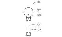
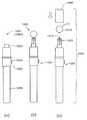
このような穿刺具は従来より種々考案されているが、一般的には図12(a)に示すような穿刺具本体1051(例えば特許文献1−4を参照)の先端に図11のようなランセット1001(例えば特許文献5、6を参照)を取り付け、先端部に開口を有する図12(c)に示すキャップ1060を装着して使用する。尚、以後図面において、穿刺具及びランセット等の上側を「先端」又は「前」と、下側を「後端」又は「後」と、また上下方向を「軸方向」とし、針プロテクター付きランセットの軸側を「内側」と、外部側を「外側」として説明する。 Various types of such puncture devices have been conventionally devised. Generally, the puncture device
図11においてランセット1001は、先端の鋭利な針1014を軸方向に固定した、例えば角柱状のランセントハブ1016に、針先1012を覆って針先保護部材1010を被せて構成される。針先保護部材1010は誤って使用者等を傷つけないよう保護するために針先1012に被嵌される。 In FIG. 11, the
また、図12(a)において、穿刺具本体1051は、円筒状のケーシング1056内にコック1058が軸方向へ往復移動可能に配設され、係止状態となったコック1058の係止を解除するためのトリガーボタン1054を側部に備えて構成されている。ケーシング1056は先端に開口を有するランセットキャリア1052を備え、この開口にランセット1001の後端部を嵌合してランセット1001を着脱自在に保持することができる(図12(b)を参照)。 In FIG. 12A, the puncture device
このような構成の穿刺具本体1051は、コック1058を後端方向へ引っ張っることによって、穿刺具本体1051に内蔵された図示しないコイルバネを圧縮しながらコック1058を後退させることができる。後退したコック1058は、トリガーボタン1054と連動する図示しない係止機構により後退位置に係止される。そして、トリガーボタン1054を押すことによって、コック1058の係止状態が解除され、圧縮されたコイルバネの弾性反発によりコック1058がケーシング1056の先端方向へ付勢されて前進移動する。このコック1058の前進移動によって、ランセットキャリア1052の先端に保持されたランセット1001の針先1012が、図12(c)に示すキャップ1060の先端の開口を介してわずかに突出し生体表面に穿刺される。その後コック1058は伸びたコイルバネが自然長に戻る力を利用して後端方向へ後退する。 The
上記した穿刺具1050は、穿刺を行なう前にランセット1001を穿刺具本体1051のランセットキャリア1052に取り付け(図12(b))、ランセット1001の針先1012を保護する針先保護部材1010を外し、穿刺具1050のキャップ1060を取り付ける(図12(c))。穿刺終了後は、穿刺具1050からキャップ1060を取り外し、ランセット1001を穿刺具本体1051から取り外し、廃棄する。血液の付着したランセット1001を介した感染を回避するため、ランセット1001は穿刺を行なう度に取り替えられ、使用後に廃棄される。 In the
しかし、これら従来の穿刺具1050は、針先保護部材1010を捻り取った際にランセット1001の鋭利な針先1012が図12(c)のように露出する。そのため、その後穿刺具1050のキャップ1060を装着する際に、誤って指先等を傷つけてしまうことがあった。 However, in these
また、使用後に穿刺装置からキャップを取り外す際にも同様の危険性がある。更に、看護士等が病棟で患者の穿刺を行なう場合、使用後の誤穿刺はHIVやB型肝炎ウイルスなどへの感染の危険性を生じ、非常に大きなリスクを伴う。 There is also a similar risk when removing the cap from the puncture device after use. Furthermore, when a nurse or the like punctures a patient in a ward, an erroneous puncture after use creates a risk of infection with HIV, hepatitis B virus, and the like, and involves a very large risk.
このような危険を回避するために、穿刺時以外は針先が露出することのない穿刺具が考案されている。 In order to avoid such a risk, a puncture device has been devised in which the needle tip is not exposed except during puncture.
例えば文献7には、再使用可能なベースユニットと使い捨て先端キャップとから構成されるランセットが開示されている。使い捨て先端キャップは、ランセットの使用前及び使用後にランセットを内部に収容することが出来る。従って、使用済みのランセットをユーザー等の指に接触させる危険性を伴わずに先端キャップごと廃棄することができる。即ち、ランセットを使用前は針先はキャップにより保護されており、ランセットを使用後は先端キャップごと廃棄するので安全である。しかし、ランセットがキャップ内で固定されておらず、使用後にキャップから針先が飛び出す可能性があるため、誤穿刺の危険性が残る。 For example, Document 7 discloses a lancet including a reusable base unit and a disposable tip cap. The disposable tip cap can accommodate the lancet inside the lancet before and after use. Therefore, the tip cap can be discarded without risk of contacting the used lancet with the finger of the user or the like. That is, the needle tip is protected by the cap before using the lancet, and the tip cap is discarded after the lancet is used, which is safe. However, since the lancet is not fixed in the cap and the needle tip may jump out of the cap after use, the risk of erroneous puncture remains.
そこで本願発明者は、上記困難を解決するため種々鋭意検討を行なった結果、針先の露出を防止し、安価で取扱い容易なランセットを考案し、本発明に至ったのである。 Accordingly, the present inventor has conducted various studies to solve the above-mentioned difficulties. As a result, the inventors have devised a lancet that prevents exposure of the needle tip, is inexpensive and easy to handle, and has reached the present invention.
即ち本発明は、穿刺前、穿刺後に穿刺具から針が露出することを防止し、誤穿刺の危険性を従来より大幅に低減させ得る針プロテクター付きランセットを提供することを目的とする。 That is, an object of the present invention is to provide a lancet with a needle protector that prevents the needle from being exposed from the puncture device before and after puncturing, and can greatly reduce the risk of erroneous puncturing.
また、本発明の別の目的は、安価に生産され、取扱いの容易な針プロテクター付きランセットを提供することにある。 Another object of the present invention is to provide a lancet with a needle protector that is inexpensively produced and easy to handle.
本発明の針プロテクター付きランセットは、針先を有する針と、前記針を針先が露出しうるように支持するランセットハブと、先端に前記針先が突出し得る開口を有し、前記針先を包囲して前記ランセットハブの少なくとも一部を収容し、かつ、該ランセットハブに対して回動可能な筒状の針プロテクターと、を備えてなり、前記ランセットハブの外側面及び前記針プロテクターの内側面には、該針プロテクターのランセットハブに対する軸方向の移動を規制する規制手段と、該規制手段が設けられていない位置に設けられ該針プロテクターのランセットハブに対する軸方向の移動を可能とする案内手段とを有してなる。 The lancet with a needle protector of the present invention has a needle having a needle tip, a lancet hub for supporting the needle so that the needle tip can be exposed, an opening through which the needle tip can protrude at a tip, and the needle tip is A cylindrical needle protector that surrounds and accommodates at least a part of the lancet hub and is rotatable with respect to the lancet hub, and includes an outer surface of the lancet hub and an inner surface of the needle protector. On the side surface, a restricting means for restricting the movement of the needle protector relative to the lancet hub and a guide provided at a position where the restricting means is not provided to allow the needle protector to move in the axial direction relative to the lancet hub. Means.
本発明の針プロテクター付きランセットは、前記規制手段は、前記ランセットハブの外側面に設けられた突起と、前記針プロテクターの内側面に形成される、前記突起と先端側から当接する第1規制手段と、同じく前記針プロテクターの内側面に形成される、前記突起と後端側から当接する第2規制手段と、から構成され得る。 In the lancet with a needle protector according to the present invention, the restricting means includes a protrusion provided on an outer surface of the lancet hub, and a first restricting means formed on the inner surface of the needle protector that contacts the protrusion from the tip side. And a second restricting means which is also formed on the inner surface of the needle protector and abuts from the rear end side.
本発明の針プロテクター付きランセットは、前記案内手段は、前記ランセットハブの突起を軸方向に案内し得るように、前記針プロテクターの内側面の規制手段が設けられていない位置に軸方向に設けられる摺動溝であり得る。 In the lancet with a needle protector according to the present invention, the guide means is provided in an axial direction at a position where no restriction means is provided on the inner surface of the needle protector so that the projection of the lancet hub can be guided in the axial direction. It may be a sliding groove.
本発明の針プロテクター付きランセットは、前記針プロテクターの内側面には、前記規制手段が設けられている位置にさらに前記ランセットハブの突起を係止し得る凹部または窓が設けられるのが好ましい。 In the lancet with a needle protector according to the present invention, it is preferable that a recess or a window capable of locking the protrusion of the lancet hub is further provided on the inner surface of the needle protector at a position where the restricting means is provided.
本発明の針プロテクター付きランセットは、前記規制手段は、前記針プロテクターの内側面に設けられた突起と前記ランセットハブの外側面に形成される、前記突起と先端側から当接する第1規制手段と、同じく前記ランセットハブの外側面に形成される、前記突起と後端側から当接する第2規制手段と、から構成されてもよい。 In the lancet with a needle protector according to the present invention, the restricting means includes a protrusion provided on the inner surface of the needle protector and a first restricting means formed on the outer surface of the lancet hub and abutting from the protrusion and the tip side. Alternatively, the projection may be formed on the outer surface of the lancet hub, and a second restricting means that abuts from the rear end side.
本発明の針プロテクター付きランセットは、前記案内手段は、前記針プロテクターの突起を軸方向に案内し得るように、前記ランセットハブの外側面の規制手段が設けられていない位置に軸方向に設けられる摺動溝であってもよい。 In the lancet with a needle protector according to the present invention, the guide means is provided in the axial direction at a position where the restricting means on the outer surface of the lancet hub is not provided so that the projection of the needle protector can be guided in the axial direction. It may be a sliding groove.
本発明の針プロテクター付きランセットは、前記ランセットハブの外側面には、前記規制手段が設けられている位置にさらに前記針プロテクターの突起を係止し得る凹部または窓が設けられてなる。 In the lancet with a needle protector according to the present invention, a concave portion or a window capable of locking the protrusion of the needle protector is further provided on the outer surface of the lancet hub at a position where the restricting means is provided.
本発明の針プロテクター付きランセットは、前記針の針先を保護する針先保護部材を有し得る。 The lancet with a needle protector of the present invention may have a needle tip protecting member that protects the needle tip of the needle.
本発明の針プロテクター付きランセットは、前記針の針先を保護する針先保護部材が前記ランセットハブと一体に成形され得る。または、本発明の針プロテクター付きランセットは、前記針の針先を保護する針先保護部材が前記針プロテクターと一体に成形されてもよい。 In the lancet with a needle protector of the present invention, a needle tip protecting member for protecting the needle tip of the needle can be formed integrally with the lancet hub. Alternatively, in the lancet with a needle protector of the present invention, a needle tip protecting member that protects the needle tip of the needle may be formed integrally with the needle protector.
本発明の針プロテクター付きランセットは、前記ランセットハブはさらに、穿刺具に回動不能に固定されるための回動抑制部材を有する。 In the lancet with a needle protector according to the present invention, the lancet hub further includes a rotation restraining member for being fixed to the puncture device so as not to rotate.
本発明の穿刺具は、前記ランセットハブを回動不能に固定するランセットキャリアを有し、かつ、針プロテクターを回動可能に装着するケーシングを有し、上記針プロテクター付きランセットを自在に着脱することができる。 The puncture device of the present invention has a lancet carrier for fixing the lancet hub so as not to rotate, and has a casing for rotatably mounting a needle protector, and the lancet with the needle protector can be freely attached and detached. Can do.
本発明の針プロテクター付きランセットは、針先保護部材を捻り取った状態であっても針プロテクターが針先を包囲するので、穿刺前、穿刺後ともにランセットから針先が露出せず安全に廃棄が可能である。即ち、ランセットハブを針プロテクター内で回動させて、針プロテクター側面に開口した窓に係止させ、更に規制手段でランセットハブの軸方向の移動を規制するので、針が針プロテクター付きランセットの外部へ露出する事故が起こる確率を極めて低くすることができ、誤穿刺の危険を従来より大幅に低減化することができる。 In the lancet with a needle protector of the present invention, the needle protector surrounds the needle tip even when the needle tip protection member is twisted, so that the needle tip is not exposed from the lancet both before and after puncturing and can be safely discarded. Is possible. That is, the lancet hub is rotated in the needle protector and locked to the window opened on the side of the needle protector, and the movement of the lancet hub in the axial direction is restricted by the restricting means. The probability of occurrence of an accident that is exposed to the eye can be made extremely low, and the risk of accidental puncture can be greatly reduced as compared with the prior art.
また、本発明の針プロテクター付きランセットは、ランセットハブ、針先保護部材及び針を金型を用いて一体成形し、針プロテクターに嵌入して製造することができる。従って十分安価に生産することができ、穿刺具への取り付け及び取り外しも従来の市販されているランセットと同様に簡単である。 Moreover, the lancet with a needle protector of the present invention can be manufactured by integrally forming a lancet hub, a needle tip protecting member and a needle using a mold and fitting the lancet into the needle protector. Therefore, it can be produced at a sufficiently low cost, and attachment to and removal from the puncture device is as simple as a conventional commercially available lancet.
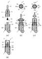
図1は本発明の針プロテクター付きランセットの一実施形態を示す斜視図である。本実施形態の針プロテクター付きランセット1の正面図及び側面図が図2及び図3に示されている。また、図4は図2に示す針プロテクター付きランセット1のA−A断面図であり、図5は図3に示す針プロテクター付きランセット1のB−B断面図である。 FIG. 1 is a perspective view showing an embodiment of a lancet with a needle protector according to the present invention. A front view and a side view of the
本発明の針プロテクター付きランセット1は、図4を参照して、針先12を有する針14と、針14を針先12が露出しうるよう支持するランセットハブ16と、先端に針先12が突出し得る開口4を有し、針先12を包囲してランセットハブ16の少なくとも一部を収容し、かつ、ランセットハブ16に対して回動可能な筒状の針プロテクター2とを備えて構成される。尚、上述のように、図面において、上側を「先端」又は「前」と、下側を「後端」又は「後」と、また上下方向を「軸方向」とし、針プロテクター付きランセットの軸側を「内側」又は「内」と、外部側を「外側」又は「外」とする。 Referring to FIG. 4, the
更に本発明の針プロテクター付きランセット1は、ランセットハブ16の外側面及び針プロテクター2の内側面に、針プロテクター2のランセットハブ16に対する軸方向の移動を規制する規制手段と、当該規制手段が設けられていない位置に設けられ針プロテクター2のランセットハブ16に対する軸方向の移動を可能とする案内手段とを有する。 Furthermore, the
以下、本発明の針プロテクター付きランセットについてその好ましい実施形態を図を用いて説明する。 Hereinafter, preferred embodiments of the lancet with a needle protector of the present invention will be described with reference to the drawings.
図4において、針プロテクター付きランセット1は針先12に針先保護部材10を被嵌して針先12を保護している。針先保護部材10とランセットハブ16は着脱方式であってもよいが、針14を挿入した状態で一体に成形する方が部品点数を減少させ、製造コストを抑えることができ、更に滅菌性の保持という点からも望ましい。この一体成形の場合は、針先保護部材10とランセットハブ16間に破断部5を肉薄に成形し、針先保護部材10を例えば捻ることで破断部5を破断してランセットハブ16と離別させればよい。 In FIG. 4, the
ランセットハブ16は、図4及び図5に示すように、側面に突起8を有し、軸部に固定した針14の針先12が上記破断部5の先端から露出しうるように形成されている。本実施形態において、ランセットハブ16は中空の円筒形状であるが、軸部で針14を支持するため、板状の回動抑制部材20が軸部を通って設けられ、円筒内部の中空部を仕切って二分している。回動抑制部材20はまた、針プロテクター付きランセット1のランセットハブ16を穿刺具のランセットキャリアに回動不能に固定するために用いられるが、針プロテクター付きランセット1を穿刺具に装着する方法については後述する。尚、針14は、長方形の回動抑制部材20の対称軸の位置に埋設されている。 As shown in FIGS. 4 and 5, the
図1に示すように針プロテクター2の先端部中央には開口4が形成されており、穿刺時には、この開口4を介して針先12が突出する。また、側面には窓22が開口されており、以下に説明するようにランセットハブ16の突起8を係止することができる。尚、窓22は、突起8を係止した状態において少なくとも針先12が開口4から突出しない好適な位置で、針プロテクター2の側面に開口される。 As shown in FIG. 1, an
本実施形態において、上記規制手段は、以下に説明する第1規制手段6と第2規制手段7から構成される。本実施形態の針プロテクター2は、内部側面に第1規制手段6と第2規制手段7が一定間隔を保って円周方向に周設されている。図4の状態において、第1規制手段6はランセットハブ16の突起8の先端部と当接する。第2規制手段7は突起8の後端部と当接する。これら第1規制手段6及び第2規制手段7は針プロテクター2内面に形成された段差であり、突起8の軸方向の移動を規制する。尚、上記第1規制手段6および第2規制手段7は突起8の軸方向の移動を規制するものであればよく、このような形状に限定されない。 In the present embodiment, the restriction means includes first restriction means 6 and second restriction means 7 described below. In the
また、本実施形態において、上記案内手段は、ランセットハブ16の突起8を軸方向に案内し得るように、針プロテクター2の内側面の上記規制手段が設けられていない位置に軸方向に設けられる摺動溝3である。図7(b)上方の平面図に示すように、摺動溝3が形成されている部分には、第1規制手段6及び第2規制手段7は形成されていない。尚、摺動溝3a,3bを総称して摺動溝3と、突起8a,8bを総称して突起8と、窓22a,22bを総称して窓22という。 Further, in the present embodiment, the guide means is provided in the axial direction at a position where the restriction means is not provided on the inner side surface of the
針プロテクター2はランセットハブ16に対して回動することができる。あるいは言い換えるとランセットハブ16は針プロテクター2内で回動することができるが、このとき突起8は円周方向に周設された第1規制手段6と第2規制手段7の間を通って移動する。図7(c)上方の平面図のように突起8が摺動溝3の位置に一致すると、第1規制手段6と第2規制手段7による軸方向の移動の規制が解除され、突起8は摺動溝3と嵌合しながら軸方向に摺動することができる。 The
また、突起8と第1規制手段6、第2規制手段7間の摩擦は小さくしてよい。しかし、図7(b)の上方の平面図において、ランセットハブ16の突起8aの外端面から対向する突起8bの外端面までの長さは針プロテクター2の内径よりわずかに長くなっており、針プロテクター2を回動させる際には突起8は針プロテクター2を外方向へわずかに押し広げながら第1規制手段6および第2規制手段7間を回動する。 Further, the friction between the
従って、針プロテクター2のランセットハブ16に対する回動はスムーズとはならず、容易に突起8が回動しないため、予期せぬ外力により突起8が回動して摺動溝3と嵌合し、針プロテクター2がランセットハブ16から脱落することを防止することができる。尚、突起8を針プロテクター2の側面に開口された上記窓22の位置に一致させると、より確実に突起8の不必要な回動を防止することが出来る。 Accordingly, the rotation of the
上記窓22は、上記針プロテクター2の第1規制手段6および第2規制手段7が設けられている位置に、上記突起8を係止し得るものであればよく、図1に示されるように針プロテクター2を貫通する窓22であってもよいが、針プロテクター2の内部に設けられた凹部であってもよい。なお、針プロテクター2を手で回動させて突起8が窓22または凹部に係止される際、突起8が針プロテクター2の内側面による圧迫から開放された感覚が手に伝わることにより、また突起8が窓22を通して目視できることにより、突起8が窓22または凹部に係止されたことを確認することができる。また、針プロテクター2を手で回動させる力により、突起8は容易に窓22または凹部との係合が解除されるものである。 The
また、図1に示すように針プロテクター2の先端部中央には開口4が形成されており、穿刺時には、この開口4を介して針先12が突出する。針プロテクター2の内側面に形成された摺動溝3の端面とこれに対向する摺動溝3の端面間の距離は、上記突起8aの外端面から対向する突起8bの外端面までの長さよりわずかに長くなっており、ランセットハブ16は針プロテクター2内を滑らかに軸方向に移動することができる。 As shown in FIG. 1, an
針プロテクター2の外周面には、針プロテクター2を回動させる際に指を掛けやすくするために、指掛け部18が形成されてもよい。図1に示される針プロテクター2は、指掛け部18を形成するために、針プロテクター2先端部が先端に向かって縮径するテーパー形状となっているが、針プロテクター2先端部を後端部と同径の円筒状とし、針プロテクター2から突出する指掛け部を形成してもよい。また、針プロテクター2は円筒形状に指掛け部18を設けた形状以外にも、外形を角柱状等あるいはその他の形状としたものであってもよい。 A
尚、針プロテクター2の材質は針先を外部露出させないよう容易に変形が起こらない材料で形成するのが望ましく、ポリプロピレン、ポリエチレン、ポリアセタール、ABS、ポリカーボネートなどが考えられるが、この限りではない。ランセットハブ16も上記材料により形成するのが好適であるが、その材料は特に限定されない。また、針14はステンレスなどの金属あるいは合成樹脂で成形されるのが好ましいが、その材料は特に限定されない。 The material of the
以上のように構成された本発明の針プロテクター付きランセット1は、針先保護部材10を捻り取った状態であっても針プロテクター2が針先12より先方まで針14を包囲するので、穿刺前、穿刺後ともに開口4から針14が露出しない。また、ランセットハブ16は、針プロテクター2の側面に開口した窓22に係止されて回動が規制され、更に上記規制手段でランセットハブの軸方向の移動を規制するので、針14が針プロテクター付きランセット1の外部へ露出する事故が起こる確率を極めて低くすることができ、誤穿刺の危険を従来より大幅に低減化することができる。 In the
次に、本発明に係る針プロテクター付きランセットの好ましい製造方法を以下に説明する。 Next, the preferable manufacturing method of the lancet with a needle protector which concerns on this invention is demonstrated below.
上述のように、ランセットハブ16、針先保護部材10及び針14は、予めこれらの外形を型どった、例えば金型を用意し、一体成形することが好ましい。まず金型の中心に針先12が先端方向となるように軸方向に針14を固定する。次に、金型内部に高温で流体状となった、例えば上記熱可塑性樹脂を流し込む。冷却により十分に型内部が固まったら、金型を外して一体成形されたランセットハブ16、針14及び針先保護部材10を取り出す。 As described above, it is preferable that the
同様に、針プロテクター2も、予め準備した金型を用いて成形する。成形材料は上述のとおりである。 Similarly, the
次に一体成形したランセットハブ16、針14及び針先保護部材10の針先保護部材10の先端側を、針プロテクター2の後端側から挿入する。この挿入の際、ランセットハブ16の側面に形成された突起8を、針プロテクター2の内面に形成された摺動溝3に位置合わせしてランセットハブ16を針プロテクター2内に嵌入する。 Next, the tip end side of the needle
最後に、ランセットハブ16を針プロテクター2内で回動させ、突起8を針プロテクター2の側面に開口された窓22に係止させ、本発明に係る針プロテクター付きランセット1が完成する。 Finally, the
以上のように本発明の針プロテクター付きランセット1は、ランセットハブ16、針先保護部材10及び針14を金型を用いて一体成形し、別途成形した針プロテクター2に嵌合して形成することができる。従って本発明の針プロテクター付きランセット1は比較的安価に生産することができる。また、本発明の針プロテクター付きランセット1は、ランセットハブ16を針プロテクター2内で回動させて窓22に係止させ、更に規制手段でランセットハブ16の軸方向の移動を規制するので、針14が針プロテクター付きランセット1の外部へ露出する事故が起こる確率は極めて低く、安全に取り扱うことができる。 As described above, the
次に、本実施形態の針プロテクター付きランセット1を装着する穿刺具について説明する。 Next, a puncture tool to which the
図4に示される本発明のランセットハブ16は後端部が円筒状であり、ランセットキャリア52は円柱状である。ランセットハブ16の円筒の内径はランセットキャリア52の円柱の外径よりもわずかに小さく形成されており、ランセットハブ16の後端部がランセットキャリア52の先端側に嵌合されることで両者は固定される。しかし本発明の針プロテクター付きランセット1は、ランセットハブ16を収容する針プロテクター2をランセットハブ16に対して回動させる必要がある。したがって、ランセットハブ16をランセットキャリア52上に回動不能に固定させるために、ランセットハブ16には回動抑制部材20を設けている。 The
上記のように、本実施形態の針プロテクター付きランセット1は板状の回動抑制部材20が軸部を通って設けられ、円筒内部の中空部を仕切って二分している。このような針プロテクター付きランセット1を装着するために、本発明に係る穿刺具50は先端に図6のようなスリットを設けた円柱状のランセットキャリア52を配設する。 As described above, in the
スリットを設けた円柱状のランセットキャリア52は、断面が半円形状の対向する2つの部材から構成され、当該2つの部材は上記板状の回動抑制部材20の厚さより心持ち広い幅をもって平行に立設される。回動抑制部材20の後端部分をこのランセットキャリア52のスリット内に挟持して、ランセットハブ16を穿刺具50の先端に回動不能に固定する。 The
回動抑制部材20の形状は図示される板状部材に限定されず、ランセットハブ16とランセットキャリア52とを回動不能に固定ものであればよい。例えば、ランセットハブ16に設けられた凸部とランセットキャリア52に設けられた凹部による凹凸嵌合であってもよい。 The shape of the
ランセットハブ16を固定することにより、針プロテクター2の例えば指掛け部18に指を掛けて針プロテクター2をランセットハブ16の回りに回動させることができる。 By fixing the
また、上述したようにランセットハブ16がランセットキャリア52に回動不能に固定される際、針プロテクター2もまた穿刺具50のケーシング56に装着される。しかし、針プロテクター2はランセットハブ16に対して回動する必要があるため、針プロテクター2と穿刺具50のケーシング56とは回動可能に装着される。 Further, as described above, when the
固定方法としては、例えば、図7(c)に示されるように針プロテクター2後端部に設けられた突部21と、ケーシング56の先端部内周面に設けられた環状凹部57とによる回動可能な係合が挙げられる。この固定方法は後述するように、針プロテクター付きランセット1を穿刺具50に装着した後に針プロテクター2を回動させたときにのみ、針プロテクター2の突部21がケーシング56の環状凹部57と係合して、針プロテクター2がケーシング56から脱落することを防止するものである。 As a fixing method, for example, as shown in FIG. 7C, rotation by a
尚、針プロテクター2の形状は、ケーシング56に挿入されうるものであり、ランセットハブ16の周囲で回動しうるものであれば特に限定されない。また、突部21の数も特に限定されないが、図7(b)、(c)、(d)に図示されるように針プロテクター2の後端部の対向する位置に2つ設けられることが好ましい。The shape of the
以下に、本実施形態の針プロテクター付きランセット1を図6に示す穿刺具50に装着して穿刺を行なう際の、針プロテクター付きランセット1の動作を説明する。本発明に係る穿刺具50は、ランセットハブ16を回動不能に固定できるランセットキャリア52と、針プロテクター2を回動可能に装着できるケーシング56とを有する以外は、上記穿刺具1050と同様市販されている公知の穿刺具と同様であってよい。従ってその構成及び機能は以下の説明において簡略に述べるにとどめることとする。 Hereinafter, the operation of the
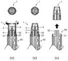
まず穿刺を行なう準備として、図7(a)のようにランセットキャリア52に針プロテクター付きランセット1を装着する。ランセットハブ16は回動抑制部材20がランセットキャリア52のスリット内に挟持されるようにランセットキャリア52に回動不能に装着され、針プロテクター2はケーシング56内に挿入される。このとき、針プロテクター2後端の突部21がケーシング56内周面に当接することにより針プロテクター2の回動が妨害されないように、ケーシング56内周面は突部21をガイドする凹部あるいは突部21が当接しない程度に十分大きい内径を有していることが好ましい。この状態でランセットハブ16の突起8は、ランセットキャリア52の窓22に係止されている。また、突起8は、ランセットキャリア52の内側面に設けられた第1規制手段6と第2規制手段7により軸方向の移動が規制されている。 First, as preparation for puncturing, the
次に、針プロテクター2の例えば指掛け部18に指を掛けて図7(b)のように針プロテクター2を回動させ、針プロテクター2とランセットハブ16との係止を解除する。続いて図7(c)上方の平面図のように突起8を摺動溝3の位置に一致させ、ランセットハブ16の第1規制手段6と第2規制手段7による軸方向の移動の規制を解除する。この時、針プロテクター2後端部の突部21はケーシング56内周面に設けられた環状凹部57に係合することにより、針プロテクター2の軸方向の移動を規制する。 Next, a finger is placed on, for example, the
その後図7(c)に示すようにランセット1より針先保護部材10を捻り取る。針先保護部材10は上記のようにランセットハブ16に一体に成形されているが、破断部5が肉薄に成形されているため、針先保護部材10を捻ることで破断され、ランセットハブ16と引き離される。このとき、図7(c)に示されるように針14の針先12は針プロテクター2で囲まれているため、従来例の準備の手順を示す図12(a)〜(c)と比較してわかるように、針先12が露出されることがなく誤穿刺の危険性がない。 Thereafter, as shown in FIG. 7C, the needle
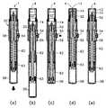
次に、穿刺時の様子を図8(a)〜図8(e)を用いて以下に説明する。 Next, the state at the time of puncturing will be described below with reference to FIGS. 8 (a) to 8 (e).
図8(a)、(b)のように、コック58を引き、穿刺具50内の発射用バネ62を圧縮させるとランセット1を装着したランセットキャリア52が後退し、図8(c)に示す穿刺準備状態(係止状態)となる。 As shown in FIGS. 8A and 8B, when the
次にトリガーボタン54を押すと、図8(d)のように発射用バネ62の圧縮が開放され、ランセット1がランセットキャリア52とともに勢いよく先端方向に前進移動する。
穿刺具50の各部の寸法および発射用バネ62、戻し用バネ63の強度の調整により、例えば戻し用バネ63の圧縮が最大となるところで針プロテクター2の前進移動が停止する。このとき針14の針先12が針プロテクター2の開口4より飛び出し生体表面への穿刺が行なわれる。Next, when the
By adjusting the size of each part of the
その後、ランセットキャリア10は発射用バネ62が自由長に戻る力と戻し用バネ63の復元力で、ランセットハブ3とともに図8(e)のように最初の位置(図8(a))に戻る。 Thereafter, the
ランセット1の取り外しは、まず、図9(a)のように針プロテクター2を回動させ、ランセットハブ16の突起8を針プロテクター2の窓22に係止する(図9(b))。この時針プロテクター2の突部21とケーシング56の環状凹部57との係合も解除され、針プロテクター付きランセット1は穿刺具50より取り外し可能となる。 To remove the
この際も、常に針プロテクター2が針先12を保護しているので、針先12が露出されることなく、安全に廃棄が可能である。また、ランセットハブ16を針プロテクター2内で回動させて窓22に係止させ、更に規制手段でランセットハブ16の軸方向の移動を規制するので、針14が針プロテクター付きランセット1の外部へ露出する事故が起こる確率を極めて低くすることができる。 Also at this time, since the
以上、本発明の好適な実施形態について説明したが、本発明に係る針プロテクター付きランセット1は上記実施形態に限定されるものではない。上記実施形態においては、規制手段は、ランセットハブ16の外側面に設けられた突起8と、針プロテクター2の内側面に形成され突起8と当接する第1規制手段及び第2規制手段とから構成された。しかし本発明の別の実施形態においては、上記規制手段は、上記突起が針プロテクターの内側面に設けられ、ランセットハブの外側面に形成される第1規制手段及び第2規制手段が上記突起に先端側と後端側から当接するように構成してもよい。 As mentioned above, although preferred embodiment of this invention was described, the
このような実施形態の針プロテクター付きランセットでは、上記案内手段としての摺動溝は、上記針プロテクターの突起を軸方向に案内し得るように、上記ランセットハブの外側面の規制手段が設けられていない位置に軸方向に設けられるのが好ましい。また、上記ランセットハブの外側面には、上記規制手段が設けられている位置にさらに上記針プロテクターの突起を係止し得る凹部または窓が設けられるのが好ましい。 In the lancet with a needle protector of such an embodiment, the sliding groove as the guide means is provided with a regulating means on the outer surface of the lancet hub so that the projection of the needle protector can be guided in the axial direction. It is preferably provided in the axial direction at no position. The outer surface of the lancet hub is preferably further provided with a recess or a window capable of locking the protrusion of the needle protector at a position where the restricting means is provided.
本実施形態の針プロテクター付きランセットも、案内手段と規制手段を設けた位置を針プロテクターとランセットハブ間で入替えた以外は、上記実施形態の針プロテクター付きランセット1と構成要素、製造方法、上記ランセットへの装着方法、またその構成の奏する作用、効果とも略同一である。従って図示及び説明は省略するが、本実施形態の針プロテクター付きランセットも、上記針プロテクター付きランセット1と同様、穿刺前、穿刺後ともにランセットから針先が露出せず安全に廃棄が可能であり、誤穿刺の危険を従来より大幅に低減化することができる。 The lancet with the needle protector of the present embodiment is the same as the
あるいは、本発明に係る他の実施形態の針プロテクター付きランセットは、穿刺時のランセットハブの前進移動を停止させる他の機構を備えてもよい。上記図8(d)のように、上記実施形態の針プロテクター付きランセット1は、戻し用バネ63の圧縮が最大となるところで針プロテクター2の前進移動が停止するが、図10の断面図に示すように、ランセットハブ116の先端側の位置で、針プロテクター102の内側面にストッパー126を設けてランセットハブ116の前進移動を停止させる機構としてもよい。 Alternatively, the lancet with a needle protector according to another embodiment of the present invention may include another mechanism that stops the forward movement of the lancet hub during puncturing. As shown in FIG. 8D, in the
あるいは上記実施形態の針プロテクター付きランセット101は、複数の位置でストッパー126を外部から挿入させることが可能な構成とし、ストッパー126を挿入させる
位置を選択することによって針が開口4から突出する長さを調整する構造としてもよい。また、穿刺具側に前進移動の距離を調節し得る機構を設けてもよい。Alternatively, the
図7(a)(b)、または図9(a)(b)において、針プロテクター2の内側面に軸方向に形成した摺動溝3は2つとしたが、摺動溝3の本数は1本でもよく、この場合ランセットハブ16の突起8も1個形成すればよい。あるいは、ランセットハブ16の突起8の位置と位置合わせをして、上記摺動溝3を3本以上形成してもよい。摺動溝3の数は、すべての突起8が摺動溝3と嵌合し得るのであれば特に限定されない。 7A, 7B, or 9A, 9B, the number of the sliding grooves 3 is 1 although the number of the sliding grooves 3 formed in the axial direction on the inner surface of the
その他、本発明に係る針プロテクター付きランセット1および穿刺具50の長さ、各種寸法、バネの強さ等は、必要に応じて好適に設計され得る。 In addition, the length, various dimensions, spring strength, and the like of the
また、上記実施形態において針プロテクター付きランセット1は、ランセットハブ16、針先保護部材10及び針14を一体成形し針プロテクター2に嵌入したが、針先保護部材10を針プロテクター2と一体成形して針プロテクター2を嵌入してもよい。あるいは各部品を別々に成形して組立ててもよい。本発明の針プロテクター付きランセット1は、製造方法は特に限定されない。 In the above embodiment, the
その他、本発明は、その主旨を逸脱しない範囲で当業者の知識に基づき種々の改良、修正、変更を加えた態様で実施できるものである。 In addition, the present invention can be carried out in a mode in which various improvements, modifications, and changes are added based on the knowledge of those skilled in the art without departing from the spirit of the present invention.
1、1001:ランセット
2:針プロテクター
3:摺動溝
4:開口
5:破断部
6:第1規制手段
7:第2規制手段
8:突起
10、1010:針先保護部材
12、1012:針先
14、1014:針
16、1016:ランセントハブ
18:指掛け部
20:回動抑制部材
21:突部
22:窓
126:ストッパー
50、1050:穿刺具
1051:穿刺具本体
52、1052:ランセットキャリア
54、1054:トリガーボタン
56、1056:ケーシング
57:環状凹部
58、1058:コック
1060:キャップ
62:発射用バネ
63:戻し用バネDESCRIPTION OF
Claims (12)
Translated fromJapanese前記針を針先が露出しうるように支持するランセットハブと、
先端に前記針先が突出し得る開口を有し、前記針先を包囲して前記ランセットハブの少なくとも一部を収容し、かつ、該ランセットハブに対して回動可能な筒状の針プロテクターと、を備えてなり、
前記ランセットハブの外側面及び前記針プロテクターの内側面には、該針プロテクターのランセットハブに対する軸方向の移動を規制する規制手段と、該規制手段が設けられていない位置に設けられ該針プロテクターのランセットハブに対する軸方向の移動を可能とする案内手段とを有してなる、
針プロテクター付きランセット。A needle having a needle tip;
A lancet hub that supports the needle so that the needle tip can be exposed;
A cylindrical needle protector having an opening through which the needle tip can protrude, encloses the needle tip, accommodates at least a part of the lancet hub, and is rotatable with respect to the lancet hub; With
The outer surface of the lancet hub and the inner surface of the needle protector are provided with a restricting means for restricting movement of the needle protector in the axial direction relative to the lancet hub, and provided at a position where the restricting means is not provided. Guide means enabling axial movement relative to the lancet hub,
Lancet with needle protector.
前記ランセットハブの外側面に設けられた突起と、
前記針プロテクターの内側面に形成される、前記突起と先端側から当接する第1規制手段と、
同じく前記針プロテクターの内側面に形成される、前記突起と後端側から当接する第2規制手段と、
から構成される、請求項1に記載の針プロテクター付きランセット。The regulating means is
A protrusion provided on the outer surface of the lancet hub;
A first restricting means that is formed on the inner surface of the needle protector and that comes into contact with the protrusion from the tip side;
A second restricting means which is also formed on the inner side surface of the needle protector and abuts from the rear end side with the projection;
The lancet with a needle protector according to claim 1, comprising:
前記ランセットハブの突起を軸方向に案内し得るように、前記針プロテクターの内側面の規制手段が設けられていない位置に軸方向に設けられる摺動溝である、
請求項2に記載の針プロテクター付きランセット。The guiding means includes
A sliding groove provided in the axial direction at a position where no restriction means is provided on the inner side surface of the needle protector so that the protrusion of the lancet hub can be guided in the axial direction.
A lancet with a needle protector according to claim 2.
前記針プロテクターの内側面に設けられた突起と
前記ランセットハブの外側面に形成される、前記突起と先端側から当接する第1規制手段と、
同じく前記ランセットハブの外側面に形成される、前記突起と後端側から当接する第2規制手段と、
から構成される、請求項1に記載の針プロテクター付きランセット。The regulating means is
First protrusions that are formed on the inner surface of the needle protector and formed on the outer surface of the lancet hub and that contact the protrusions from the tip side;
A second restricting means, which is also formed on the outer surface of the lancet hub, abutting from the rear end side with the protrusion;
The lancet with a needle protector according to claim 1, comprising:
前記針プロテクターの突起を軸方向に案内し得るように、前記ランセットハブの外側面の規制手段が設けられていない位置に軸方向に設けられる摺動溝である、
請求項5に記載の針プロテクター付きランセット。The guiding means includes
A sliding groove provided in the axial direction at a position where no restricting means is provided on the outer surface of the lancet hub so that the projection of the needle protector can be guided in the axial direction;
The lancet with a needle protector according to claim 5.
請求項8に記載の針プロテクター付きランセット。The needle tip protection member is formed integrally with the lancet hub;
The lancet with a needle protector according to claim 8.
請求項8に記載の針プロテクター付きランセット。The needle tip protection member is formed integrally with the needle protector;
The lancet with a needle protector according to claim 8.
The lancet with a needle protector according to claim 1, which has a lancet carrier for fixing the lancet hub so as not to rotate, and a casing on which the needle protector is rotatably mounted. Puncture tool.
Priority Applications (1)
| Application Number | Priority Date | Filing Date | Title |
|---|---|---|---|
| JP2004269996AJP2006081751A (en) | 2004-09-16 | 2004-09-16 | Lancet with needle protector and puncture instrument with the same |
Applications Claiming Priority (1)
| Application Number | Priority Date | Filing Date | Title |
|---|---|---|---|
| JP2004269996AJP2006081751A (en) | 2004-09-16 | 2004-09-16 | Lancet with needle protector and puncture instrument with the same |
Publications (1)
| Publication Number | Publication Date |
|---|---|
| JP2006081751Atrue JP2006081751A (en) | 2006-03-30 |
Family
ID=36160705
Family Applications (1)
| Application Number | Title | Priority Date | Filing Date |
|---|---|---|---|
| JP2004269996APendingJP2006081751A (en) | 2004-09-16 | 2004-09-16 | Lancet with needle protector and puncture instrument with the same |
Country Status (1)
| Country | Link |
|---|---|
| JP (1) | JP2006081751A (en) |
Cited By (2)
| Publication number | Priority date | Publication date | Assignee | Title |
|---|---|---|---|---|
| JP2010535604A (en)* | 2007-08-14 | 2010-11-25 | オウエン マンフォード リミティド | Surgical needle device |
| JP2014168534A (en)* | 2013-03-01 | 2014-09-18 | Sysmex Corp | Puncture device |
Citations (3)
| Publication number | Priority date | Publication date | Assignee | Title |
|---|---|---|---|---|
| JPH0588503A (en)* | 1991-09-27 | 1993-04-09 | Canon Inc | Electrifying device |
| JPH11164825A (en)* | 1997-11-21 | 1999-06-22 | Mercury Diagnostics Inc | Sampling device of humor |
| JP2004113580A (en)* | 2002-09-27 | 2004-04-15 | Ra Systems:Kk | Lancet |
- 2004
- 2004-09-16JPJP2004269996Apatent/JP2006081751A/enactivePending
Patent Citations (3)
| Publication number | Priority date | Publication date | Assignee | Title |
|---|---|---|---|---|
| JPH0588503A (en)* | 1991-09-27 | 1993-04-09 | Canon Inc | Electrifying device |
| JPH11164825A (en)* | 1997-11-21 | 1999-06-22 | Mercury Diagnostics Inc | Sampling device of humor |
| JP2004113580A (en)* | 2002-09-27 | 2004-04-15 | Ra Systems:Kk | Lancet |
Cited By (2)
| Publication number | Priority date | Publication date | Assignee | Title |
|---|---|---|---|---|
| JP2010535604A (en)* | 2007-08-14 | 2010-11-25 | オウエン マンフォード リミティド | Surgical needle device |
| JP2014168534A (en)* | 2013-03-01 | 2014-09-18 | Sysmex Corp | Puncture device |
Similar Documents
| Publication | Publication Date | Title |
|---|---|---|
| EP1632179B1 (en) | Lancet with needle protector | |
| US7785338B2 (en) | Lancing aid comprising a lancet system that is protected against re-use | |
| EP1790287B1 (en) | Centesis instrument | |
| EP1865849B1 (en) | Push activation lancet device | |
| US7524308B2 (en) | Safety shielding needle assembly with passive shielding | |
| AU2011201205B2 (en) | Rotary-actuated medical puncturing device | |
| US9649053B2 (en) | Cam-actuated medical puncturing device and method | |
| JPH03502421A (en) | hypodermic syringe | |
| US10602969B2 (en) | Method of reuse protection for lancet system | |
| JP2005312763A (en) | Cartridge for puncture needle, puncture equipment, tip unit and adaptor | |
| JP4820822B2 (en) | Puncture device | |
| JP2006081751A (en) | Lancet with needle protector and puncture instrument with the same | |
| JP4544002B2 (en) | Lancet with needle protector | |
| JP4736042B2 (en) | Indwelling needle |
Legal Events
| Date | Code | Title | Description |
|---|---|---|---|
| A621 | Written request for application examination | Free format text:JAPANESE INTERMEDIATE CODE: A621 Effective date:20070914 | |
| A977 | Report on retrieval | Free format text:JAPANESE INTERMEDIATE CODE: A971007 Effective date:20100623 | |
| A131 | Notification of reasons for refusal | Free format text:JAPANESE INTERMEDIATE CODE: A131 Effective date:20100712 | |
| A02 | Decision of refusal | Free format text:JAPANESE INTERMEDIATE CODE: A02 Effective date:20101104 |