JP2006079852A - Light guide plate and display device - Google Patents
Light guide plate and display deviceDownload PDFInfo
- Publication number
- JP2006079852A JP2006079852AJP2004259965AJP2004259965AJP2006079852AJP 2006079852 AJP2006079852 AJP 2006079852AJP 2004259965 AJP2004259965 AJP 2004259965AJP 2004259965 AJP2004259965 AJP 2004259965AJP 2006079852 AJP2006079852 AJP 2006079852A
- Authority
- JP
- Japan
- Prior art keywords
- light
- light guide
- guide plate
- diffraction grating
- emitted
- Prior art date
- Legal status (The legal status is an assumption and is not a legal conclusion. Google has not performed a legal analysis and makes no representation as to the accuracy of the status listed.)
- Pending
Links
Images


Landscapes
- Light Guides In General And Applications Therefor (AREA)
- Liquid Crystal (AREA)
- Planar Illumination Modules (AREA)
Abstract
Translated fromJapaneseDescription
Translated fromJapanese本発明は、光源からの光を導光する導光板、およびこの導光板から出射される光を照明光として用いるディスプレイ装置に関する。 The present invention relates to a light guide plate that guides light from a light source, and a display device that uses light emitted from the light guide plate as illumination light.
LCDを用いたディスプレイ装置は、軽量かつコンパクトな設計が可能となることから、パソコンやテレビ等に広く利用されている。この種のディスプレイ装置は、マトリクス内に配置された複数のピクセルからなり、マトリクス内の各ピクセルは、制御信号に応答して、光がディスプレイ内を通過できるようにする光バルブを備えている。このディスプレイを照明するために、ディスプレイの背面にバックライトが配置されている。 Display devices using LCDs are widely used in personal computers and televisions because they can be designed to be lightweight and compact. This type of display device consists of a plurality of pixels arranged in a matrix, and each pixel in the matrix includes a light valve that allows light to pass through the display in response to a control signal. In order to illuminate the display, a backlight is disposed on the back of the display.
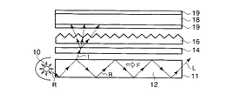
このようなバックライトには、平面状の導光板が用いられているものがある。図6は、このようなバックライトを適用したディスプレイ装置の一般的な構成を示す概念図である。すなわち、光源10から、例えば白色光のようなランダムな光Rが照射されると、この光Rは、導光板12内を導光方向Fに沿って導光される。そして、その導光途中において、導光板12の外部に漏れ出た光Iが拡散フィルム14によって拡散され、その後プリズムシート16を介した後にLCD18に入射する。 Some backlights use a planar light guide plate. FIG. 6 is a conceptual diagram showing a general configuration of a display device to which such a backlight is applied. That is, when random light R such as white light is irradiated from the
すなわち、拡散フィルム14は、この光Iを拡散して、LCD18の表面全体を等しく照明するために用いられている。また、プリズムシート16は、LCD18の輝度を増加させるために用いられている。 That is, the
このような構成によって、LCD18の輝度をある程度増加することはできるが、光源10からの光Rの利用率はさほど高い訳ではない。というのも、光源10からの光Rは、その60〜70%程度のみが光IとしてLCD18の照明に用いられ、30〜40%程度は、導光板12の終端部11まで導光され、そこからそのまま光Lとしてリークしてしまうからである。 With such a configuration, the luminance of the
しかも、LCD18は、光Iに含まれる偏光光のうち、直線的なS偏光光を必要とするので、光Iに含まれるP偏光光を遮光し、光Iに含まれるS偏光光のみを取り出す図示しない偏光子が含まれている。この偏光子によって、プリズムシート16を介して入射する光Iのうちの、P偏光光は使用されず、残りの約半分であるS偏光光しかLCD18の照明に使用されておらず、照明効率が高くない。この対策として、LCD18の表面を偏光板19によって覆うことが一般的になった。 In addition, since the
このような偏光板19を用いることによって、S偏光光を再利用できるようになり、LCD18の輝度を若干増加させることができるようになった。しかしながら、依然として、光源10からの光Rのうちの30〜40%程度は、終端部11からリークしてしまい、LCD18の照明に全く寄与しておらず、光Rの利用効率は低い。 By using such a polarizing
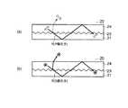
光源10からの光Rの利用効率の向上を図るためになされた発明としては、下記特許文献1に記載された導光板がある。この導光板20は、図7に示すように、複屈折率を有する複屈折材からなる基材21を、コーティング材24でコーティングすることによって形成されている。また、基材21とコーティング材24との境界には、透過型の回折格子23が設けられている。 As an invention made to improve the utilization efficiency of the light R from the
この場合も同様に、光源から例えば白色光のようなランダムな光Rが照射されると、この光Rは、導光板20内をほぼ導光方向Fに沿って導光される。そして、その導光途中において、回折格子23の透過時に回折された光Iが、導光板20の外部に出射される。 In this case as well, when random light R such as white light is irradiated from the light source, the light R is guided along the light guide direction F in the
例えば、図7に示すように、回折された光Iが出射されるような場合、その回折効率は、入力光である光Rの偏光状態に依存し、図8(a)に示すようにP偏光光が出射されるTMモードに対するよりも、図8(b)に示すようにS偏光光が出射されるTEモードに対する方が高い。 For example, when the diffracted light I is emitted as shown in FIG. 7, the diffraction efficiency depends on the polarization state of the light R that is the input light, and P as shown in FIG. It is higher for the TE mode in which S-polarized light is emitted as shown in FIG. 8B than in the TM mode in which polarized light is emitted.
したがって、図7に示すような構成とすることによって、導光板20から出射される光Iに含まれるS偏光光の割合を高めることができる。これによって、光Iの出射後に導光板20に残った光Rには、P偏光光が多く残るようになるものの、複屈折材は、光Rの偏光状態を変化させる作用を有しているので、P偏光光がS偏光光に変化させられ、逆にS偏光光の割合が多くなる。これによって、次の回折出射時には、S偏光光の光の割合が高い光Iが、効率良く導光板20から出射するようになる。 Therefore, with the configuration shown in FIG. 7, the proportion of S-polarized light included in the light I emitted from the
このようなメカニズムが導光板20の導光方向Fに沿って繰り返されることによって、導光板20の終端部11からリークする光Lの量が減少し、光源10からの光Rの利用効率の向上が図られている。
しかしながら、このような従来の導光板は、以下のような問題がある。 However, such a conventional light guide plate has the following problems.
すなわち、上記特許文献1の発明の導光板20は、図7に示すように、基材21とコーティング材24との2層によって構成され、両層の境界線上に回折格子23が設けられている。 That is, as shown in FIG. 7, the
このような構成では、導光板20内を導光される光Rは、基材21の部位でのみ偏光作用がなされ、コーティング材24の部位では偏光されないために、偏光効率は必ずしも高い訳ではなく、光Rの利用効率の更なる向上を図る余地が残されている。 In such a configuration, the light R guided through the
また、構成が複雑であるので、光Rを回折出射させるために必要な基材21とコーティング材24との屈折率差を大きく取ることが困難であること、更に、回折格子23は透過型であることから、回折格子23にて生じる回折の効率が低く、さほど強い光を出射できないという問題がある。 Further, since the configuration is complicated, it is difficult to obtain a large difference in refractive index between the
本発明はこのような事情に鑑みてなされたものであり、光源から入射された光の利用効率を更に高めるとともに、強い光を出射することが可能な導光板および、この導光板をバックライトとして用いたディスプレイ装置を提供することを目的とする。 The present invention has been made in view of such circumstances, and further improves the utilization efficiency of the light incident from the light source and can emit strong light, and the light guide plate as a backlight. An object of the present invention is to provide a display device used.
上記の目的を達成するために、本発明では、以下のような手段を講じる。 In order to achieve the above object, the present invention takes the following measures.
すなわち、本発明の導光体は、光源から内側に入射された光を導光する導光部と、導光部の内部に、光が導光される導光方向に対してほぼ直交する面を含むように導光部の一部を置き換えるように配置された複屈折率部材と、導光部の内側表面に導光方向に沿って配置され、導光部によって導光された光が、導光部の内側から外側へ出射されるように、導光された光を回折反射させる回折格子とを備えている。複屈折率部材は、好ましくは、導光部の導光方向長さに対するほぼ中央に配置する。また、複数備えていても良い。 That is, the light guide of the present invention has a light guide portion that guides light incident inward from the light source, and a surface that is substantially orthogonal to the light guide direction in which light is guided inside the light guide portion. A birefringent member arranged so as to replace a part of the light guide unit so as to include, and the light guided by the light guide unit arranged along the light guide direction on the inner surface of the light guide unit, A diffraction grating for diffracting and reflecting the guided light is provided so as to be emitted from the inside to the outside of the light guide unit. The birefringent member is preferably arranged at the approximate center with respect to the length of the light guide portion in the light guide direction. A plurality of them may be provided.
また、この回折格子は、ボリュームタイプ、あるいはレリーフタイプの何れのタイプのものも適用することができる。また、好ましくは、回折格子の格子間隔を0.1μm以上2μm以下とする。0.1μm未満では製造が困難となり、逆に2μmよりも大きくなると回折格子の数が少なくなってしまい、十分な効果が得られなくなるからである。 In addition, the diffraction grating can be applied to either a volume type or a relief type. Preferably, the grating interval of the diffraction grating is 0.1 μm or more and 2 μm or less. If the thickness is less than 0.1 μm, manufacturing becomes difficult. Conversely, if the thickness is larger than 2 μm, the number of diffraction gratings decreases, and a sufficient effect cannot be obtained.
このような手段を講じることにより、構成を簡素化し、更に、透過型の回折格子よりも強い光を出射することができる。また、導光部の内部には複屈折率部材を、導光方向長さのほぼ中央に配置するか、または複数配置していることから、複屈折率部材に到達する前に既に回折格子によってS偏光光が出射しておりP偏光光が多く含まれている光を、S偏光光に効率良く偏光することができる。これによって、その後の出射において出射光に含まれるS偏光光の割合を高めることができるとともに、導光部から出射されずにそのままリークする光を低減することができるようになり、光源からの光の利用効率を高めることが可能となる。 By taking such means, the configuration can be simplified, and more intense light than that of the transmission type diffraction grating can be emitted. In addition, since the birefringence member is arranged in the middle of the light guide direction length or a plurality of birefringence members are arranged in the inside of the light guide unit, the diffraction grating is already used before reaching the birefringence member. Light that is emitted from S-polarized light and contains a large amount of P-polarized light can be efficiently polarized into S-polarized light. As a result, the ratio of the S-polarized light contained in the emitted light in the subsequent emission can be increased, and the light leaking without being emitted from the light guide unit can be reduced, and the light from the light source can be reduced. It becomes possible to increase the use efficiency of the.
また、回折格子を導光部と同一材料で形成してもよい。これによって、本発明の導光板を一体的に製造することが可能となる。 Further, the diffraction grating may be formed of the same material as the light guide. This makes it possible to manufacture the light guide plate of the present invention integrally.
以上のような導光板と、光源と、導光板から出射された光によって照明されるLCDとを備えたディスプレイ装置を構成することによって、このディスプレイ装置は、より高性能となり、例えば、従来と同じ性能の光源を使っても、従来よりも明るく表示することが可能となる。あるいは、従来よりも暗い能力の低い光源を用いても、従来と同程度の明るさで表示することができることから、必要電力の低減化、光源の小型化、光学素子の減少等により低廉化を図ることが可能となる。 By configuring a display device including the light guide plate, the light source, and the LCD illuminated by the light emitted from the light guide plate, the display device has higher performance. Even if a light source with high performance is used, it is possible to display brighter than before. Alternatively, even if a light source with a darker capacity than before is used, it is possible to display with the same level of brightness as in the past. It becomes possible to plan.
本発明の導光板によれば、構成を簡素化し、透過型の回折格子よりも強い光を出射することができる。また、導光部の導光方向に対する中央に一つ、あるいは導光方向に沿って複数複屈折率部材を配置していることから、複屈折率部材に到達する前に既に回折格子によってS偏光光が出射しておりP偏光光が多く含まれている光を、S偏光光に効率良く偏光することができる。これによって、その後の出射において出射光に含まれるS偏光光の割合を高めることができるとともに、導光部から出射されずにそのままリークする光を低減することができるようになり、光源からの光の利用効率を高めることが可能となる。 According to the light guide plate of the present invention, the configuration can be simplified and light stronger than that of the transmission type diffraction grating can be emitted. In addition, one birefringence member is arranged in the center of the light guide portion with respect to the light guide direction, or a plurality of birefringence members are arranged along the light guide direction. Light that is emitted and contains a large amount of P-polarized light can be efficiently polarized into S-polarized light. As a result, the ratio of the S-polarized light contained in the emitted light in the subsequent emission can be increased, and the light leaking without being emitted from the light guide unit can be reduced, and the light from the light source can be reduced. It becomes possible to increase the use efficiency of the.
また、以上のような導光板と、光源と、導光板から出射された光によって照明されるLCDとを備えたディスプレイ装置を構成することによって、このディスプレイ装置は、より高性能となり、例えば、従来と同じ性能の光源を使っても、従来よりも明るく表示することが可能となる。あるいは、従来よりも暗い能力の低い光源を用いても、従来と同程度の明るさで表示することができることから、必要電力の低減化、光源の小型化、光学素子の減少等により低廉化を図ることが可能となる。 In addition, by configuring a display device including the light guide plate, the light source, and the LCD illuminated by the light emitted from the light guide plate, the display device has higher performance. Even if a light source with the same performance is used, it is possible to display brighter than before. Alternatively, even if a light source with a darker capacity than before is used, it is possible to display with the same level of brightness as in the past. It becomes possible to plan.
以下に、本発明を実施するための最良の形態について図面を参照しながら説明する。 The best mode for carrying out the present invention will be described below with reference to the drawings.
なお、以下の実施の形態の説明に用いる図中の符号は、図6乃至図8と同一部分については同一符号を付して示すことにする。 In addition, the code | symbol in the figure used for description of the following embodiment attaches | subjects and shows the same code | symbol about the same part as FIG. 6 thru | or FIG.
図1は、本発明の実施の形態に係る導光板の構成例を示す断面図である。 FIG. 1 is a cross-sectional view illustrating a configuration example of a light guide plate according to an embodiment of the present invention.
すなわち、同実施の形態に係る導光板2は、光源10から内側に入射された光Rを導光する導光部3と、導光部3の内部に、光Rが導光される導光方向Fに対してほぼ直交する面を含むように導光部3の一部を置き換えるように配置された複屈折率部材6とを備えている。この複屈折率部材6は、導光部3の導光方向F長さに対するほぼ中央に配置する。同実施の形態では、複屈折率部材6よりも導光方向Fに対して上流側の導光部3を前半部3a、下流側を後半部3bと称するものとする。複屈折率部材6としては、PET、PCB、アクリル等の多くのタイプのプラスチック材を使用することが可能である。 That is, the
また、導光部3の内側表面に導光方向Fに沿って配置され、導光部3によって導光された光Rが、導光部3の内側から外側へ出射されるように回折反射させる反射型の回折格子4を備えている。 Further, the light R disposed along the light guide direction F on the inner surface of the
図1に示す回折格子4は、レリーフタイプのものを示しているが、このような導光板2に代えて、図2に示すように、ボリュームタイプの回折格子4’を用いた導光板2’を用いることも可能である。 The
回折格子4の格子間隔としては、好ましくは、0.1μm以上2μm以下とする。0.1μm未満では製造が困難となり、逆に2μmよりも大きくなると回折格子の数が少なくなってしまい、十分な効果が得られなくなるからである。回折格子4と導光部3とは、同一材料で形成してもよい。これによって、導光板2を一体的に製造することが可能となる。また、回折格子4の外側(非導光部3側)に、回折格子4を透過した光を導光部3側に戻すために、反射体5を配置するようにしても良い。 The grating interval of the
次に、以上のように構成した同実施の形態に係る導光板2の作用について説明する。 Next, the operation of the
すなわち、光源10から、例えば白色光のようなランダムな光Rが導光部3の内部に入射すると、この光Rは、導光部3内を導光方向Fに沿って導光される。そして、その導光途中において、導光部3の内側表面に、導光方向Fに沿って配置された反射型の回折格子4によって回折反射された光R’は、導光部3の外部へと出射される。 That is, when random light R such as white light enters the
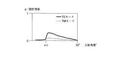
図3は、同実施の形態に係る導光板2の前半部3aにおける回折格子4による1次回折反射光の回折効率を示すグラフである。 FIG. 3 is a graph showing the diffraction efficiency of the first-order diffracted reflected light by the
横軸が、導光部3の内側表面に対する光Rの入射角度であり、縦軸は回折効率を示す。このグラフは、回折格子4として2000ライン/mmのブレーズドレリーフ型回折格子、導光部3の屈折率として1.5、入射光Rの波長として500nmの条件において、光RのうちのS偏光光が回折されるTEモードと、光RのうちのP偏光光が回折されるTMモードとのそれぞれについて計算した結果である。なお、αcは臨界角である。図3に示すように、TEモードの回折効率は、TMモードの数倍であるので、前半部3aでは、S偏光光がP偏光光よりも数倍多く出射される。 The horizontal axis represents the incident angle of the light R with respect to the inner surface of the
一方、このように、一度の光Iの出射によって、S偏光光がP偏光光よりも数倍多く出射されることから、複屈折率部材6に到達する光Rには、P偏光光が多く含まれるようになる。しかしながら、複屈折率部材6では光Rが偏光されることから、後半部3bにおいては、光RにはS偏光光が多く含まれるようになる。 On the other hand, since the S-polarized light is emitted several times more than the P-polarized light by the emission of the light I at this time, the light R reaching the
図3に示すように、S偏光光は、導光部3から効率良く出射されるので、S偏光光が多く含まれる後半部3bでは、回折格子4によって光Rがより効率良く出射される。その結果、導光部3の終端部11からリークする光Lが減り、逆に光源10からの光Rのほとんどが導光部3の外へと出射される。しかも、この出射光Iは、S偏光光の割合が高められている。 As shown in FIG. 3, since the S-polarized light is efficiently emitted from the
なお、回折格子4の表面で回折した光Rの一部は、そのまま回折格子4を透過して導光部3の外部へ漏れ出る恐れがある。しかしながら、回折格子4の外側(非導光部3側)に、反射体5を配置することによって、回折格子4を透過した光を反射し、導光部3内に戻すことによって、導光部3の外部に光が漏れ出ることが阻止される。 A part of the light R diffracted on the surface of the
図4に示すように、導光板2に、更に拡散フィルム14、プリズムシート16、LCD18を付加してディスプレイ装置を構成した場合、前述したようにLCD18ではS偏光光のみが照明光として使用される。したがって、このようなディスプレイ装置は、同実施の形態に係る導光板2から出射されるS偏光光の割合が高い光Iを、照明光として用いることから、LCD18が極めて効率良く照明される。 As shown in FIG. 4, when the display device is configured by further adding the
上述したように、同実施の形態に係る導光板2においては、上記のような作用により、構成を簡素化し、更に、透過型の回折格子よりも強い光を出射することができる。また、導光部3の前半部3aと後半部3bとの間に複屈折率部材6を配置していることから、P偏光光が多く含まれた状態で複屈折率部材6に入射した光Rを、S偏光光が多く含まれる光Rに変換した後に後半部3bに導くことができる。 As described above, in the
これによって、後半部3bからの出射光Iに含まれるS偏光光の割合を高めることができるとともに、導光部3から出射されずにそのまま終端部11からリークする光Lを低減することができるようになり、光源10からの光の利用効率を高めることが可能となる。 As a result, the ratio of the S-polarized light contained in the outgoing light I from the
また、以上のような導光板2と、光源10と、導光板2から出射された光Iによって照明されるLCD18とを備えたディスプレイ装置を構成することによって、このディスプレイ装置は、より高性能となり、例えば、従来と同じ性能の光源を使っても、従来よりも明るく表示することが可能となる。あるいは、従来よりも暗い能力の低い光源を用いても、従来と同程度の明るさで表示することができることから、必要電力の低減化、光源の小型化、光学素子の減少等により低廉化を図ることが可能となる。 In addition, by configuring the display device including the
以上、本発明を実施するための最良の形態について、添付図面を参照しながら説明したが、本発明はかかる構成に限定されない。特許請求の範囲の発明された技術的思想の範疇において、当業者であれば、各種の変更例及び修正例に想到し得るものであり、それら変更例及び修正例についても本発明の技術的範囲に属するものと了解される。 The best mode for carrying out the present invention has been described above with reference to the accompanying drawings, but the present invention is not limited to such a configuration. Within the scope of the invented technical idea of the scope of claims, a person skilled in the art can conceive of various changes and modifications. The technical scope of the present invention is also applicable to these changes and modifications. It is understood that it belongs to.
たとえば、導光板2を、図1に示す構成の代わりに、図5に示す構成としても良い。図5に示す導光板2では、導光部3の内部に、導光方向Fに対してほぼ直交する面を含むように導光部3の一部を置き換えるように、複数の複屈折率部材6(#1〜#5)を、好ましくは等間隔で備えている。 For example, the
このような構成とすることによって、導光部領域3(#1)においてS偏光光が多く出射され、P偏光光の割合が高められた状態で複屈折率部材6(#1)に入射した光Rは、複屈折率部材6(#1)によってS偏光光の割合が高められた後に導光部領域3(#2)に入射する。従って、導光部領域3(#2)では、効率良く光Iが出射される。 With this configuration, a large amount of S-polarized light is emitted from the light guide region 3 (# 1) and is incident on the birefringence member 6 (# 1) in a state where the proportion of P-polarized light is increased. The light R is incident on the light guide region 3 (# 2) after the ratio of S-polarized light is increased by the birefringence member 6 (# 1). Accordingly, the light I is emitted efficiently in the light guide region 3 (# 2).
同様に、導光部領域3(#2)においてS偏光光が多く出射され、P偏光光の割合が高められた状態で複屈折率部材6(#2)に入射した光Rは、複屈折率部材6(#2)によってS偏光光の割合が高められた後に導光部領域3(#3)に入射する。従って、導光部領域3(#3)では、効率良く光Iが出射される。 Similarly, a large amount of S-polarized light is emitted from the light guide region 3 (# 2), and the light R incident on the birefringence member 6 (# 2) in a state where the ratio of P-polarized light is increased is birefringent. After the ratio of the S-polarized light is increased by the index member 6 (# 2), the light enters the light guide region 3 (# 3). Therefore, the light I is efficiently emitted from the light guide region 3 (# 3).
このようなメカニズムが繰り返されることによって、各導光部領域3(#1〜#5)の何れから出射されるIに含まれるS偏光光の割合をも高めることができるとともに、導光部3から出射されずにそのまま終端部11からリークする光Lを低減することができるようになり、光源10からの光の利用効率を高めることが可能となる。 By repeating such a mechanism, the ratio of S-polarized light contained in I emitted from any of the light guide region 3 (# 1 to # 5) can be increased, and the
F…導光方向、2…導光板、3…導光部、4…回折格子、5…反射体、6…複屈折率部材、10…光源、11…終端部、12…導光板、14…拡散フィルム、16…プリズムシート、18…LCD、19…偏光板、20…導光板、21…基材、23…回折格子、24…コーティング材 F ... Light guide direction, 2 ... Light guide plate, 3 ... Light guide part, 4 ... Diffraction grating, 5 ... Reflector, 6 ... Birefringence member, 10 ... Light source, 11 ... Termination part, 12 ... Light guide plate, 14 ... Diffusion film, 16 ... Prism sheet, 18 ... LCD, 19 ... Polarizing plate, 20 ... Light guide plate, 21 ... Base material, 23 ... Diffraction grating, 24 ... Coating material
Claims (8)
Translated fromJapanese前記導光部の内部に、前記光が導光される導光方向に対してほぼ直交する面を含むように前記導光部の一部を置き換えるように配置された複屈折率部材と、
前記導光部の内側表面に前記導光方向に沿って配置され、前記導光部によって導光された光が、前記導光部の内側から外側へ出射されるように、前記導光された光を回折反射させる回折格子と
を備えた導光板。A light guide for guiding light incident inward from the light source;
A birefringence member disposed inside the light guide so as to replace a part of the light guide so as to include a surface substantially orthogonal to the light guide direction in which the light is guided;
The light that is disposed along the light guide direction on the inner surface of the light guide and guided by the light guide is emitted from the inside to the outside of the light guide. A light guide plate comprising a diffraction grating that diffracts and reflects light.
前記複屈折率部材を、前記導光部の前記導光方向長さに対するほぼ中央に配置した導光板。The light guide plate according to claim 1,
A light guide plate in which the birefringence member is disposed substantially at the center of the light guide portion with respect to the length of the light guide direction.
前記複屈折率部材を複数備えた導光板。The light guide plate according to claim 1,
A light guide plate comprising a plurality of the birefringence members.
前記回折格子を、ボリュームタイプの回折格子とした導光板。The light guide plate according to any one of claims 1 to 3,
A light guide plate in which the diffraction grating is a volume type diffraction grating.
前記回折格子を、レリーフタイプの回折格子とした導光板。The light guide plate according to any one of claims 1 to 3,
A light guide plate in which the diffraction grating is a relief type diffraction grating.
前記回折格子の格子間隔を0.1μm以上2μm以下とした導光板。The light guide plate according to any one of claims 1 to 5,
A light guide plate in which a grating interval of the diffraction grating is 0.1 μm or more and 2 μm or less.
前記回折格子を前記導光部と同一材料で形成した導光板。The light guide plate according to any one of claims 1 to 6,
A light guide plate in which the diffraction grating is formed of the same material as the light guide.
前記導光板に備えられた導光部の内側に入射される光を照射する光源と、
前記導光部から出射された光によって照明されるLCDと
を備えたディスプレイ装置。The light guide plate according to any one of claims 1 to 7,
A light source for irradiating light incident on the inside of the light guide provided in the light guide plate;
A display device comprising: an LCD that is illuminated by light emitted from the light guide unit.
Priority Applications (1)
| Application Number | Priority Date | Filing Date | Title |
|---|---|---|---|
| JP2004259965AJP2006079852A (en) | 2004-09-07 | 2004-09-07 | Light guide plate and display device |
Applications Claiming Priority (1)
| Application Number | Priority Date | Filing Date | Title |
|---|---|---|---|
| JP2004259965AJP2006079852A (en) | 2004-09-07 | 2004-09-07 | Light guide plate and display device |
Publications (1)
| Publication Number | Publication Date |
|---|---|
| JP2006079852Atrue JP2006079852A (en) | 2006-03-23 |
Family
ID=36159140
Family Applications (1)
| Application Number | Title | Priority Date | Filing Date |
|---|---|---|---|
| JP2004259965APendingJP2006079852A (en) | 2004-09-07 | 2004-09-07 | Light guide plate and display device |
Country Status (1)
| Country | Link |
|---|---|
| JP (1) | JP2006079852A (en) |
Citations (8)
| Publication number | Priority date | Publication date | Assignee | Title |
|---|---|---|---|---|
| JPH07248496A (en)* | 1994-03-11 | 1995-09-26 | Shimada Precision Kk | Back light transmission plate utilizing differaction grating |
| JPH09218407A (en)* | 1995-12-05 | 1997-08-19 | Canon Inc | Illumination device and liquid crystal device including the illumination device |
| JPH09325218A (en)* | 1996-05-31 | 1997-12-16 | Shimada Precision Kk | Light guide plate and light guide assembly |
| JPH10125121A (en)* | 1996-10-22 | 1998-05-15 | Matsushita Electric Ind Co Ltd | Backlight |
| JPH11287993A (en)* | 1998-04-01 | 1999-10-19 | Shimada Precision Kk | Light guide plate for spot light source |
| JP2002182210A (en)* | 2000-12-19 | 2002-06-26 | Dainippon Printing Co Ltd | Reflective and transmissive liquid crystal display |
| JP2003207646A (en)* | 2000-12-28 | 2003-07-25 | Fuji Electric Co Ltd | Light guide plate and liquid crystal display device provided with this light guide plate |
| JP2004213025A (en)* | 2003-01-07 | 2004-07-29 | Samsung Electronics Co Ltd | Backlight unit |
- 2004
- 2004-09-07JPJP2004259965Apatent/JP2006079852A/enactivePending
Patent Citations (8)
| Publication number | Priority date | Publication date | Assignee | Title |
|---|---|---|---|---|
| JPH07248496A (en)* | 1994-03-11 | 1995-09-26 | Shimada Precision Kk | Back light transmission plate utilizing differaction grating |
| JPH09218407A (en)* | 1995-12-05 | 1997-08-19 | Canon Inc | Illumination device and liquid crystal device including the illumination device |
| JPH09325218A (en)* | 1996-05-31 | 1997-12-16 | Shimada Precision Kk | Light guide plate and light guide assembly |
| JPH10125121A (en)* | 1996-10-22 | 1998-05-15 | Matsushita Electric Ind Co Ltd | Backlight |
| JPH11287993A (en)* | 1998-04-01 | 1999-10-19 | Shimada Precision Kk | Light guide plate for spot light source |
| JP2002182210A (en)* | 2000-12-19 | 2002-06-26 | Dainippon Printing Co Ltd | Reflective and transmissive liquid crystal display |
| JP2003207646A (en)* | 2000-12-28 | 2003-07-25 | Fuji Electric Co Ltd | Light guide plate and liquid crystal display device provided with this light guide plate |
| JP2004213025A (en)* | 2003-01-07 | 2004-07-29 | Samsung Electronics Co Ltd | Backlight unit |
Similar Documents
| Publication | Publication Date | Title |
|---|---|---|
| KR102586389B1 (en) | Mode switchable backlight, privacy display and method using emitter arrays | |
| US7068910B2 (en) | Light generating device having polarized light emitting waveguide plate | |
| US6648485B1 (en) | Highly collimating tapered light guide for uniform illumination of flat panel displays | |
| US7859610B2 (en) | Planar lighting and LCD device with a laser light source emitting a linearly-polarized laser beam, optical member to parallelize the beam and a plate-shaped light guide for emitting part of the beam | |
| KR101402188B1 (en) | Illumination system and display device | |
| TWI285284B (en) | Backlight device and liquid crystal display device | |
| JP4339873B2 (en) | Backlight module | |
| KR20200081510A (en) | Mode-switchable backlight, display and method | |
| KR20080048759A (en) | Light guide unit, backlight unit and display device employing the same | |
| JP2005504413A (en) | Waveguide, edge illumination illumination device and display device having such a waveguide or device | |
| JPH11232919A (en) | Front light lighting system and reflecting type display device | |
| JP2008288195A (en) | Backlight unit with reduced color separation containing polarization conversion film | |
| JPH10161123A (en) | Lighting device and display device | |
| JP4784110B2 (en) | Illumination device and liquid crystal display device | |
| JP4517794B2 (en) | Light guide plate and display device | |
| JP2009003412A (en) | Polarization turning film with reduced color separation | |
| KR101414605B1 (en) | Backlight unit and display device having the same | |
| JP2006079852A (en) | Light guide plate and display device | |
| KR100682875B1 (en) | Light guide plate with multi-cycle pattern and lighting device for display device using same | |
| JP4389604B2 (en) | Illumination device and display device | |
| JP2007200740A (en) | Backlight unit and liquid crystal display device | |
| JP3952859B2 (en) | Light guide sheet and display illumination device using the same | |
| JP4184889B2 (en) | Surface light source element and display device using the same | |
| JP2004265797A (en) | Surface light source having internal diffusion means | |
| JP4645150B2 (en) | Backlight unit |
Legal Events
| Date | Code | Title | Description |
|---|---|---|---|
| A621 | Written request for application examination | Free format text:JAPANESE INTERMEDIATE CODE: A621 Effective date:20070824 | |
| A977 | Report on retrieval | Free format text:JAPANESE INTERMEDIATE CODE: A971007 Effective date:20090520 | |
| A131 | Notification of reasons for refusal | Free format text:JAPANESE INTERMEDIATE CODE: A131 Effective date:20100112 | |
| A521 | Written amendment | Free format text:JAPANESE INTERMEDIATE CODE: A523 Effective date:20100310 | |
| A02 | Decision of refusal | Free format text:JAPANESE INTERMEDIATE CODE: A02 Effective date:20100831 |