JP2006074477A - Terminal device for communication, method for changing function setting of terminal device for communication and its program - Google Patents
Terminal device for communication, method for changing function setting of terminal device for communication and its programDownload PDFInfo
- Publication number
- JP2006074477A JP2006074477AJP2004255822AJP2004255822AJP2006074477AJP 2006074477 AJP2006074477 AJP 2006074477AJP 2004255822 AJP2004255822 AJP 2004255822AJP 2004255822 AJP2004255822 AJP 2004255822AJP 2006074477 AJP2006074477 AJP 2006074477A
- Authority
- JP
- Japan
- Prior art keywords
- change detection
- function
- setting
- terminal device
- situation
- Prior art date
- Legal status (The legal status is an assumption and is not a legal conclusion. Google has not performed a legal analysis and makes no representation as to the accuracy of the status listed.)
- Pending
Links
- 238000004891communicationMethods0.000titleclaimsabstractdescription35
- 238000000034methodMethods0.000titleclaimsabstractdescription28
- 238000001514detection methodMethods0.000claimsabstractdescription162
- 230000005484gravityEffects0.000claimsdescription37
- 238000011084recoveryMethods0.000claimsdescription2
- 230000006870functionEffects0.000abstractdescription108
- 230000001413cellular effectEffects0.000description38
- 238000010586diagramMethods0.000description23
- 230000036760body temperatureEffects0.000description11
- 230000005540biological transmissionEffects0.000description8
- 230000007704transitionEffects0.000description6
- 238000006243chemical reactionMethods0.000description5
- 230000005236sound signalEffects0.000description2
- 238000000926separation methodMethods0.000description1
- 230000001960triggered effectEffects0.000description1
Images


Classifications
- H—ELECTRICITY
- H04—ELECTRIC COMMUNICATION TECHNIQUE
- H04W—WIRELESS COMMUNICATION NETWORKS
- H04W8/00—Network data management
- H04W8/22—Processing or transfer of terminal data, e.g. status or physical capabilities
- H04W8/24—Transfer of terminal data
- H04W8/245—Transfer of terminal data from a network towards a terminal
- H—ELECTRICITY
- H04—ELECTRIC COMMUNICATION TECHNIQUE
- H04W—WIRELESS COMMUNICATION NETWORKS
- H04W8/00—Network data management
- H04W8/22—Processing or transfer of terminal data, e.g. status or physical capabilities
Landscapes
- Engineering & Computer Science (AREA)
- Databases & Information Systems (AREA)
- Computer Networks & Wireless Communication (AREA)
- Signal Processing (AREA)
- Telephone Function (AREA)
- Mobile Radio Communication Systems (AREA)
Abstract
Description
Translated fromJapanese本発明は、通信用端末装置、通信用端末装置の機能設定変更方法及びそのプログラムに関する。 The present invention relates to a communication terminal device, a function setting changing method for a communication terminal device, and a program thereof.
近年、通信用端末の一つである携帯電話が普及し、その機能は電話機能だけでなく、電子メール送受信機能等も備えるようになっている。各種の設定モードとしては、受話音量設定、着信音設定、電子メールアドレス設定等の各種の設定モードがある。また、例えば、使用者が会議室、電車の中など通話に適さない場所に移動したときに、着信音などで周りの人々に迷惑を与えないようにするために、着信音が鳴動せずバイブレーション等により着信を知らせるマナーモード機能などもある。
これらの設定モードは、使用者自身が状況に応じて所定の設定モードを選択するものである。この設定モードの変更は、使用者自身が携帯電話の表示部に表示された画面を見ながら、キー操作を行うことによってなされる。In recent years, mobile phones, which are one of communication terminals, have become widespread, and their functions include not only a telephone function but also an e-mail transmission / reception function. As various setting modes, there are various setting modes such as a reception volume setting, a ringing tone setting, and an e-mail address setting. In addition, for example, when a user moves to a place that is not suitable for a call such as a conference room or train, the ringtone does not ring to vibrate so as not to disturb the people around. There is also a manner mode function that notifies incoming calls.
In these setting modes, the user himself selects a predetermined setting mode according to the situation. The change of the setting mode is performed by the key operation while the user himself / herself looks at the screen displayed on the display unit of the mobile phone.
一方、使用者自身が操作をしなくても携帯電話のある特定の設定モードのみを自動的に変更するシステムとして、例えば、特許文献1に開示された携帯電話を用いた警備システムがある。
この携帯電話を用いた警備システムでは、警備領域を警備する警備状態と警備しない解除状態との2つの警備モードを設け、着信を受けたとき、送信側の携帯電話番号を取得し、取得した電話番号を予め登録した携帯電話の電話番号と比較照合し、送信側の携帯電話番号は予め登録した携帯電話の電話番号と一致する場合、自動的に現警備モードを他の警備モードに切り替える。On the other hand, for example, there is a security system using a mobile phone disclosed in
In this security system using a mobile phone, there are two security modes, a security state that guards the security area and a release state that is not guarded. When an incoming call is received, the mobile phone number on the sending side is acquired, and the acquired phone The number is compared with the phone number of the mobile phone registered in advance, and if the mobile phone number on the transmission side matches the phone number of the mobile phone registered in advance, the current security mode is automatically switched to another security mode.
また、使用者自身が操作をしなくても携帯電話の電話帳データを自動的に登録する携帯電話(例えば、特許文献2参照)がある。この携帯電話を新規に購入したときや、機種変更したときなどに、受信した電子メールの中に、所定の書式や形式の電話帳データが含まれている場合に、その電話帳データを新規登録するか、あるいは、既登録の電話帳データの書き換えを行う。
しかしながら、従来の携帯電話では、機能及び設定モードを変更したいときには、使用者が携帯電話の表示部に表示された画面を見ながら、一連の操作を行わなければならないので面倒である。
また、特許文献1に開示された携帯電話は、警備システムという特殊な用途のみに使用されるものであり、一般的な携帯電話における機能及び設定を自動的に変更することはできないものである。
また、特許文献2に開示された携帯電話は、電話帳データを自動的に登録または書き換えを行うものであり、それ以外の機能及び設定モード変更は自動的に行うことはできないものである。However, in the conventional mobile phone, when it is desired to change the function and the setting mode, it is troublesome because the user has to perform a series of operations while looking at the screen displayed on the display unit of the mobile phone.
Further, the mobile phone disclosed in
Further, the mobile phone disclosed in Patent Document 2 automatically registers or rewrites phone book data, and other functions and setting mode changes cannot be automatically performed.
ところで、1台の携帯電話を仕事用と個人用とで使い分ける場合は、機能の固有値をそれぞれの場合に応じて変更すると、非常に便利である。
このような機能の固有値としては、例えば、タスクがカレンダーに記録されており指定時刻にアラームなどでタスクの所在を通知する機能の固有値、メールなどで文章作成する際に変換候補や入力予測候補を表示する機能の固有値、目的別に分類されたアプリケーション群をグループとして管理する機能の固有値、メールアドレス帳に登録されたメールアドレスを表示する機能の固有値などがある。
しかしながら、従来の携帯電話では、1台の携帯電話で仕事用と個人用の各機能の固有値を簡単に切り替えて使用することは困難である。By the way, when one mobile phone is used separately for work and personal use, it is very convenient to change the eigenvalue of the function according to each case.
As the eigenvalues of such functions, for example, the task is recorded in the calendar, the eigenvalue of the function that notifies the location of the task by an alarm at a specified time, the conversion candidate or the input prediction candidate when creating a sentence by e-mail etc. There are a unique value of a function to be displayed, a unique value of a function for managing an application group classified by purpose as a group, a unique value of a function for displaying a mail address registered in a mail address book, and the like.
However, with a conventional mobile phone, it is difficult to easily switch and use the eigenvalues of each function for work and personal use with one mobile phone.
本発明が解決しようとする課題(目的)は、外界の状況に応じて機能及び設定モードを自動的に変更することができる通信用端末装置、通信用端末装置の機能設定変更方法及びそのプログラムを提供することがその一例として挙げられる。 A problem (object) to be solved by the present invention is to provide a communication terminal device capable of automatically changing the function and setting mode according to the external environment, a function setting changing method for the communication terminal device, and a program thereof. Providing is one example.
請求項1に記載の通信用端末装置は、外界状況の変化を検出し、外界状況変化検出信号を送信する状況変化検出手段と、前記外界状況変化検出信号を受信することにより、記憶手段に記憶されている所定の機能及び/又は設定を読み出して、機能及び/又は設定を変更する制御手段と、を有することを特徴とする。 The communication terminal device according to
請求項13に記載の通信用端末装置の機能設定変更方法は、外界状況の変化を検出し、外界状況変化検出信号を送信するステップと、前記外界状況変化検出信号を受信することにより、記憶手段に記憶されている所定の機能及び/又は設定を読み出して、機能及び/又は設定を変更するステップと、を含むことを特徴とする。 14. The function setting changing method for a communication terminal apparatus according to
請求項14に記載の通信用端末装置の機能設定変更プログラムは、コンピュータに、外界状況の変化を検出し、外界状況変化検出信号を送信する機能と、前記外界状況変化検出信号を受信することにより、記憶手段に記憶されている所定の機能及び/又は設定を読み出して、機能及び/又は設定を変更する機能と、を実現させることを特徴とする。 The function setting change program for a communication terminal device according to
以下、本発明に係る通信用端末装置の実施の形態について、図面を参照して詳細に説明する。本実施の形態では、携帯電話装置を通信用端末装置の一例とする。
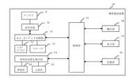
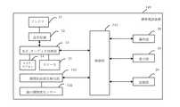
図1は、本発明の実施の形態に係る携帯電話装置の全体構成を示すブロック図である。
図1において、本実施の形態の携帯電話装置10は、アンテナ12と、送受信部13と、RF,オーディオ処理部14と、マイクロフォン15と、スピーカ16と、センサー17と、状況変化検出部18と、操作部19と、表示部20と、記憶部21と、制御部11とで構成されている。Embodiments of a communication terminal device according to the present invention will be described below in detail with reference to the drawings. In this embodiment, a mobile phone device is an example of a communication terminal device.
FIG. 1 is a block diagram showing the overall configuration of a mobile phone device according to an embodiment of the present invention.
In FIG. 1, a
送受信部13は、アンテナ12を介して図示しない基地局と所定の周波数帯域による無線信号の送受信を行う。
RF,オーディオ処理部14は、送受信部13によって送受信される無線信号の変復調や各種データの判定及び分離などの各種処理や、分離された音声データを復調し、スピーカ16に出力したり、マイクロフォン15で取得した音声データを変調し、処理したりするものである。The transmission /
The RF and
マイクロフォン15は、外部音声を集音して電気信号に変換し、変換した音声信号をRF,オーディオ処理部14に送出する。
スピーカ16は、RF,オーディオ処理部14から出力される音声信号の再生を行うもので、通話相手の音声や着信音を出力したりする。
センサー17は、外界状況を電気信号に変換して、状況変化検出部18に出力するものであり、外界状況の変化が発生したとき電気信号も変化して、状況変化検出部18に出力する。The
The
The
状況変化検出部18は、センサー17からの電気信号を受信し、受信した電気信号が変化したとき、外界状況の変化が発生したことを検出し、その外界状況の変化が発生したことを制御部11に通知する。
操作部19は、数字キーや文字キーと各種機能キーなどを有して構成され、電話番号や文字などの入力、電話番号設定、着信音設定、着信音量設定、メールアカウント設定等各種操作に用いられる。The situation
The
表示部20は、操作部19から入力されたデータや動作中の機能の状態等を表示するものである。 The
記憶部21は、制御部11の制御プログラムを含む各種の情報の記憶や、制御部11の処理に用いられる各種のデータを一時的に記憶するためのメモリである。 The
また、操作部19による入力された各種設定も記憶する。本発明の実施の形態では、電話番号とメールアカウントを仕事時間用と個人生活時間用と区別して設定することができるので、ここで、その設定を区別して記憶しておく。すなわち、本発明の実施の形態では、記憶部21は複数の電話番号設定とメールアカウント設定を記憶することができる。 In addition, various settings input by the
制御部11は、携帯電話装置10の各部と接続されており、携帯電話装置10全体の制御を行うものであり、操作部19からの各種指示の入力、送受信部13における送受信の制御、RF,オーディオ処理部14における各種処理の制御、電話及びメール着信通知音データの送出制御などの各種制御を行う。また、状況変化検出部18からの検出信号の出力結果に基づいて、携帯電話装置10の機能及び設定の変更の制御を行う。 The
ここで、制御部11により制御される機能及び設定の変更は、例えば、仕事の時間帯から個人生活の時間帯に変化したとき、電話番号とメールアカウントを仕事時間用から個人生活時間用への設定変更や、使用者がいる場所が変化したとき、着信音量の設定変更及びそれらの設定変更の対応する機能変更などである。 Here, the change of the function and setting controlled by the
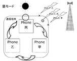
図2〜図4は、本発明の実施の形態における、電話番号の変遷イメージ及び制御部の制御により設定変更の例を示す図であり、図2は通常モードを示す図、図3は昼モードを示す図、図4は夜モードを示す図である。
図2に示す通常モードは電話番号甲を保持し、図3に示す昼モードは電話番号丙を保持し、図4に示す夜モードは電話番号乙を保持する。
さらに、図5は、本発明の実施の形態における、電話番号の変遷イメージ及び制御部の制御により状況に応じて、アカウント名、電話番号、電子メールアドレス、着信音量、着信音、壁紙、カラーパターンなどをそれぞれ変更した例である。2 to 4 are diagrams showing an example of a change of setting by control of the telephone number transition image and the control unit in the embodiment of the present invention, FIG. 2 is a diagram showing a normal mode, and FIG. 3 is a day mode. FIG. 4 is a diagram showing the night mode.
The normal mode shown in FIG. 2 holds the telephone number A, the daytime mode shown in FIG. 3 holds the telephone number 丙, and the night mode shown in FIG. 4 holds the telephone number B.
Further, FIG. 5 shows an account name, a phone number, an e-mail address, a ring volume, a ring tone, a wallpaper, a color pattern depending on the situation according to the transition image of the phone number and the control of the control unit in the embodiment of the present invention. This is an example of changing each of the above.
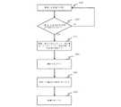
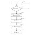
次に、本発明の実施の形態に係る携帯電話装置10について、制御部11を中心とした外界状況変化時の動作を図6に示すフローチャートに基づいて説明する。 Next, with respect to the
はじめに、センサー17は外界状況に関する情報を取得し、電気信号に変換し、状況変化検出部18に送信する(ステップS1)。
状況変化検出部18はセンサー17から送信された電気信号を解析し、外界状況の変化が発生したか否かを検出して(ステップS2)、変化が発生した場合(YES)に、外界状況変化検出信号を制御部11に送信する。First, the
The situation
一方、ステップS2において、外界状況に変化が発生していない場合(NO)は、ステップS301に戻り、外界状況の情報取得を継続する。 On the other hand, if no change has occurred in the external environment in step S2 (NO), the process returns to step S301, and acquisition of information on the external environment is continued.
制御部11は、状況変化検出部18からの外界状況変化検出信号を受信することにより、記憶部21から変化した外界状況に対応する機能及び設定を読み出し、携帯電話装置10の設定変更を行う(ステップS3)。
例えば、携帯電話装置10の設定がα=x、β=y、γ=zであった場合、外界状況の変化が発生したので、携帯電話装置10の設定をα=x、β=y、γ=zからα=x´、β=y´、γ=z´に変更する。The
For example, when the settings of the
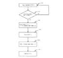
さらに、制御部11は、携帯電話装置10の機能の変更を行う(ステップS4)。
例えば、携帯電話装置10の機能が設定α=x、β=y、γ=zに対応する機能Aと機能Bであった場合、その機能を設定α=x´、β=y´、γ=z´に対応する機能Cと機能Dに変更する。Furthermore, the
For example, if the functions of the
携帯電話装置10は、変更した機能及び設定で動作する(ステップS5)。そして、処理が終了する(ステップS6)。 The
以上説明したように、状況変化検出部18は、外界状況の変化を検出し、外界状況変化検出信号を制御部11に送出する。
制御部11は、状況変化検出部18からの外界状況変化検出信号を受信すると、記憶部21に記憶されている変化した外界状況に対応する機能及び設定を読み出して、携帯電話装置10の機能及び設定を自動的に変更する。
このため、外界状況が変化するとき、その変化に応じて携帯電話装置の機能及び設定は自動的に変更することができる。As described above, the situation
When the
For this reason, when the external environment changes, the function and setting of the mobile phone device can be automatically changed according to the change.
なお、制御部11は、外界状況変化検出信号を受信した際に、機能のみ、あるいは、設定のみを変更するようにしてもよい。 Note that the
上記の外界状況としては、様々な状況が考えられる。その様々な外界状況に関する情報を取得するセンサー17も、取得する情報に応じて様々な種類のセンサーを用いることができる。以下、外界状況の例として実施例1〜実施例9を挙げて詳細に説明する。 Various situations can be considered as the above-mentioned outside world situation. Various types of sensors can also be used for the
実施例1は、仕事の時間帯から個人生活の時間帯への切り替わりを検知して、電話番号、メールアドレス、着信音量、着信音等を自動的に仕事専用から個人専用に変化する例である。
図7は、本実施例に係る携帯電話装置40の構成を示すブロック図である。The first embodiment is an example in which a change from a work time zone to a personal life time zone is detected, and a telephone number, an e-mail address, a ring volume, a ring tone, etc. are automatically changed from work-only to individual-only. .
FIG. 7 is a block diagram illustrating a configuration of the
実施例1の携帯電話装置40は、図1に示す携帯電話装置10の構成において、センサーとして時計42とカレンダー43とを用いたものである。この例では、状況変化検出手段として時間帯変化検出部44を設けた。なお、図1に示した携帯電話装置10と同一の構成要素には、同一の符号を付してその説明を省略する。 The
時間帯変化検出部44は、時計42から現在の時刻を取得し、カレンダー43から現在の日付・曜日を取得し、予め設定された仕事の時間帯及び個人生活の時間帯のどちらの時間帯に該当するかを判断し、時間帯が切り替わったと判定した場合、時間帯変化検出信号を制御部41に送出する。 The time zone change detection unit 44 obtains the current time from the clock 42, obtains the current date / day of the week from the
制御部41は、時間帯変化検出部44からの時間帯変化検出信号を受信すると、記憶部21から仕事の時間帯または個人生活の時間帯用の電話番号、メールアドレス、着信音量、着信音等を読み出して、携帯電話装置40の設定、すなわち、電話番号、メールアドレス、着信音量、着信音等の各設定を切り替わった時間帯用の設定に変更する。
また、携帯電話装置40の機能も変更後の電話番号、メールアドレス、着信音量、着信音等の各設定に対応する機能に変更するよう制御する。ここで、機能の変更例としては、例えば、以下のものがある。When the
In addition, the function of the
(1)スケジュール:タスクがカレンダーに記録されており、指定時刻にアラームなどでタスクの所在を通知する機能。
変化の一例としては、例えば、優先通知するスケジュールが「仕事に行うべきタスク」から「個人生活に行うべきタスク」に変化する。
(2)辞書:メールなどで文章作成する際に、変換候補や入力予測候補を表示する機能。
変化の一例としては、例えば、優先表示する候補一覧が「仕事に頻出の語句、文」から「個人生活に頻出の語句、文」に変化する。
(3)アプリケーションジャンル:目的別に分類されたアプリケーション群をグループとして管理する機能。
変化の一例としては、例えば、優先使用するアプリケーションジャンル一覧が「仕事に必要なアプリケーションジャンル」から「個人生活に必要なアプリケーションジャンル」に変化する。(1) Schedule: A function in which a task is recorded in a calendar, and the location of the task is notified by an alarm at a specified time.
As an example of the change, for example, the priority notification schedule changes from “task to be performed for work” to “task to be performed for personal life”.
(2) Dictionary: A function for displaying conversion candidates and input prediction candidates when creating a sentence by e-mail or the like.
As an example of the change, for example, the candidate list to be preferentially displayed changes from “words and sentences frequently appearing at work” to “words and sentences frequently appearing in personal life”.
(3) Application genre: A function for managing application groups classified by purpose as a group.
As an example of the change, for example, the application genre list to be preferentially used changes from “application genre necessary for work” to “application genre necessary for personal life”.
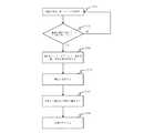
図8は、時間帯が変化するとき、携帯電話装置40の動作を示すフローチャートである。
はじめに、時計42から現在の時刻を取得し、カレンダー43から現在の日付・曜日を取得する(ステップS101)。
そして、予め設定された仕事の時間帯及び個人生活の時間帯のどちらの時間帯に該当するかを判断し(ステップS102)、時間帯が切り替わったと判定した場合(YES)、時間帯変化検出信号を制御部41に送出する。FIG. 8 is a flowchart showing the operation of the
First, the current time is acquired from the clock 42, and the current date / day of the week is acquired from the calendar 43 (step S101).
Then, it is determined which time zone corresponds to a preset time zone for work or personal life (step S102), and when it is determined that the time zone has changed (YES), a time zone change detection signal Is sent to the
ステップS102において、時間帯が切り替わっていないと判定した場合(NO)、ステップS101に戻り、再び時間帯変化の検出を行う。 If it is determined in step S102 that the time zone has not been switched (NO), the process returns to step S101, and the change in the time zone is detected again.
制御部41は、時間帯変化検出信号を受信することにより、携帯電話装置40の設定、すなわち、電話番号、メールアドレス、着信音量、着信音等の各設定を変更する(ステップS103)。 By receiving the time zone change detection signal, the
さらに、制御部41は、携帯電話装置40の機能に対して、各設定に対応する機能に変更する(ステップS104)。
これにより、携帯電話装置40は、変更した機能及び設定で動作する(ステップS105)。そして、処理が終了する(ステップS106)。Furthermore, the
Thereby, the
このように、実施例1では、時計42から取得した現在の時刻と、カレンダー43から取得した仕事の時間帯または個人生活の時間帯の情報により、時間帯が切り替わったか否かを判断し、切り替わった場合に、携帯電話装置40の設定、すなわち、電話番号、メールアドレス、着信音量、着信音等の各設定を変更する。
これにより、時間帯が切り替わるとき、携帯電話装置の機能及び設定は自動的に仕事の時間帯用の機能及び設定から個人生活の時間帯用の機能及び設定へ、あるいは、個人生活の時間帯用の機能及び設定から仕事の時間帯用の機能及び設定に変更することができる。As described above, in the first embodiment, it is determined whether or not the time zone has been switched based on the current time acquired from the clock 42 and the information on the work time zone or the personal life time zone acquired from the
Thus, when the time zone is switched, the function and setting of the mobile phone device automatically changes from the function and setting for the work time zone to the function and setting for the personal life time zone, or for the time zone of the personal life time. It is possible to change from the function and setting to the function and setting for work hours.
実施例2は、携帯電話装置を所持している使用者がジョギングなどの運動をしている時と平常時とにおいて、その機能及び設定が異なるようにした例である。例えば、使用者の身体状況変化を脈拍、体温の変化によって検知し、電話番号、メールアドレス、着信音量、着信音等を自動的に変化させる例である。
図9は、本実施例に係る携帯電話装置60の構成を示すブロック図である。The second embodiment is an example in which the functions and settings are different between when the user carrying the mobile phone device is exercising such as jogging and during normal times. For example, it is an example in which a change in a user's physical condition is detected by a change in pulse and body temperature, and a telephone number, a mail address, a ring volume, a ring tone, etc. are automatically changed.
FIG. 9 is a block diagram illustrating a configuration of the
実施例2の携帯電話装置60は、図1に示す携帯電話装置10の構成において、センサーとして、体温計62と心拍計63とを用いたものである。この例では、状況変化検出手段として、身体状況変化検出部64を設けた。なお、図1に示した携帯電話装置10と同一の構成要素には、同一の符号を付してその説明を省略する。 The
身体状況変化検出部64は、体温計62で体温を取得し、心拍計63で心拍数を取得して、体温または心拍数が平常値より変化があるとき、身体状況変化検出信号を制御部61に送出する。 The physical condition
制御部61は、身体状況変化検出部64からの身体状況変化検出信号を受信すると、携帯電話装置60の設定、すなわち、電話番号、メールアドレス、着信音量、着信音等の各設定を身体の回復度合い(心拍、体温の変化)に応じて変更する。また、携帯電話装置60の機能も変更後の電話番号、メールアドレス、着信音量、着信音等の各設定に対応する機能に変更するよう制御する。 Upon receiving the physical condition change detection signal from the physical condition
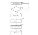
図10は、身体状況が変化するとき、携帯電話装置60の動作を示すフローチャートである。
身体状況変化検出部64は、体温計62で体温を取得し、心拍計63で心拍数を取得する(ステップS201)。
そして、体温と心拍数が平常時の範囲から外れるように変化したか否かを判定し(ステップS202)、正常な範囲から外れるように変化した場合(YES)、身体状況が変化したとして、身体状況変化検出信号を制御部61に送出する。FIG. 10 is a flowchart showing the operation of the
The physical condition
Then, it is determined whether or not the body temperature and the heart rate have changed so as to deviate from the normal range (step S202). If the body temperature and the heart rate have changed so as to deviate from the normal range (YES), A situation change detection signal is sent to the
ステップS202において、体温と心拍数が平常時の範囲内であり、身体状況の変化がないと判定した場合、ステップS201に戻る。 If it is determined in step S202 that the body temperature and the heart rate are within the normal range and there is no change in the physical condition, the process returns to step S201.
制御部61は、身体状況変化検出信号を受信することにより、携帯電話装置60の設定、すなわち、電話番号、メールアドレス、着信音量、着信音等の各設定を変更する(ステップS203)。 The
さらに、制御部61は、携帯電話装置60の機能に対して、各設定に対応する機能に変更する(ステップS204)。
これにより、携帯電話装置60は、変更した機能及び設定で動作する(ステップS205)。そして、処理が終了する(ステップS206)。Furthermore, the
Thereby, the
このように、実施例2では、体温計62及び心拍計63で取得した体温と心拍数により、身体状況に変化があるか否かを判断し、身体状況に変化があると判定したときに、携帯電話装置60の設定、すなわち、電話番号、メールアドレス、着信音量、着信音等の各設定を身体状況(体温、心拍数の変化)に応じて変更する。
これにより、使用者の身体状況が運動時の場合と平常時の場合において、携帯電話装置の機能及び設定を自動的に変更することができる。さらに、例えば、運動後の身体状況の回復に応じて、徐々に着信音量を下げるなどのように、身体状況(体温、心拍数の変化)の細かい変化に応じて携帯電話装置の機能及び設定を細かく変化させることもできる。Thus, in Example 2, it is determined whether there is a change in the physical condition based on the body temperature and heart rate acquired by the thermometer 62 and the
Thereby, the function and setting of the mobile phone device can be automatically changed when the physical condition of the user is during exercise and during normal times. In addition, the functions and settings of the mobile phone device can be set according to small changes in the physical condition (changes in body temperature and heart rate), such as gradually lowering the ring volume according to the recovery of the physical condition after exercise. It can also be changed finely.
実施例3は、ポケットの中など暗い場所に移動したときに、着信音量が自動的にバイブレーションモードに変化する例である。
図11は、本実施例に係る携帯電話装置80の構成を示すブロック図である。The third embodiment is an example in which the ring volume automatically changes to the vibration mode when moving to a dark place such as in a pocket.
FIG. 11 is a block diagram illustrating a configuration of the
実施例3の携帯電話装置80は、図1に示す携帯電話装置10の構成において、センサーとして、外界明度センサー82を用いたものである。この例では、状況変化検出手段として、明度状況変化検出部83を設けた。なお、図1に示した携帯電話装置10と同一の構成要素には、同一の符号を付してその説明を省略する。 The
外界明度センサー82は、外界明度を電気信号に変換するものであり、変換で得た電気信号を明度状況変化検出部83に送出する。
明度状況変化検出部83は、外界明度センサー82からの電気信号により、現在の外界明度値を取得し、現在の外界明度値で示した外界明度が基準となる所定の明度より暗いとき、明度状況変化検出信号を制御部81に送出する。
制御部81は、明度状況変化検出部83からの明度状況変化検出信号を受信すると、携帯電話装置80の設定、すなわち、着信設定をバイブレーションモードに変更する。また、携帯電話装置80の機能も変更後のバイブレーションモードに対応する機能に変更するよう制御する。The
The lightness status
When the
図12は、明度状況が変化するとき、携帯電話装置80の動作を示すフローチャートである。
明度状況変化検出部83は、外界明度センサー82で外界明度を取得する(ステップS301)。
そして、現在の外界明度が基準となる所定の明度より暗いか否かを判定し(ステップS302)、現在の外界明度が基準となる所定の明度より暗いと判定した場合(YES)、明度状況変化検出信号を制御部81に送出する。FIG. 12 is a flowchart showing the operation of the
The lightness status
Then, it is determined whether or not the current external brightness is darker than the reference predetermined brightness (step S302). If it is determined that the current external brightness is darker than the reference predetermined brightness (YES), the brightness status change A detection signal is sent to the
ステップS302において、現在の外界明度が基準となる所定の明度より暗くないと判定した場合、ステップS301に戻り、再び外界明度センサー82から現在の明度を取得する。
制御部81は、明度状況変化検出部83からの明度状況変化検出信号を受信すると、携帯電話装置80の設定、すなわち、着信設定をバイブレーションモードに変更する(ステップS303)。また、携帯電話装置80の機能も変更後のバイブレーションモードに対応する機能に変更する(ステップS304)。
これにより、携帯電話装置80は、変更した機能及び設定で動作する(ステップS305)。そして、処理が終了する(ステップS306)。If it is determined in step S302 that the current external brightness is not darker than the predetermined predetermined brightness, the process returns to step S301, and the current brightness is acquired from the
Upon receiving the lightness status change detection signal from the lightness status
Thereby, the
このように、実施例3では、外界明度センサー82から取得した外界明度により、現在外界明度が基準となる所定の明度より暗いかを判断し、現在の外界明度値で示す外界明度が基準となる所定の明度より暗いと判定したときに、携帯電話装置80の設定、すなわち、着信設定をバイブレーションモードに変更する。
これにより、ポケットの中など暗い場所に移動した場合に、携帯電話装置の着信設定を自動的にバイブレーションモードに変更することができる。As described above, in the third embodiment, it is determined whether the current external lightness is darker than the predetermined lightness based on the external lightness acquired from the
Thereby, when moving to a dark place such as in a pocket, the incoming call setting of the mobile phone device can be automatically changed to the vibration mode.
実施例4は、会議室、電車の中など通話に適さない場所に移動したときに、着信音が自動的に無音に変化する、もしくは携帯電話装置の電源を切る例である。
図13は、本実施例に係る携帯電話装置100の構成を示すブロック図である。The fourth embodiment is an example in which the ringtone automatically changes to silence when the user moves to a place not suitable for a call such as a conference room or a train, or the mobile phone device is turned off.
FIG. 13 is a block diagram illustrating a configuration of the
実施例4の携帯電話装置100は、図1に示す携帯電話装置10の構成において、センサーとしてGPS102用いたものである。この例では、状況変化検出手段として、場所変化検出部103を設けた。なお、図1に示した携帯電話装置10と同一の構成要素には、同一の符号を付してその説明を省略する。 The
GPS(Global Positioning System)102は、GPS衛星からの測位信号を受信して自己の現在位置を検出するものである。
位置状況変化検出部103は、GPS102から現在の位置情報を取得し、現在の位置は会議室、電車の中など通話に適さない場所であるとき、場所変化検出信号を制御部101に送出する。A GPS (Global Positioning System) 102 receives a positioning signal from a GPS satellite and detects its current position.
The position status
制御部101は、場所変化検出部103からの場所変化検出信号を受信すると、携帯電話装置100の設定、すなわち、着信音を無音にする、もしくは、携帯電話装置の電源を切るように変更する。また、携帯電話装置100の機能も変更後の各設定に対応する機能に変更するよう制御する。 Upon receiving the location change detection signal from the location
図14は、場所が変化するとき、携帯電話装置100の動作を示すフローチャートである。
場所変化検出部103は、GPS102から現在の位置を取得する(ステップS401)。
そして、現在の位置が会議室、電車の中など通話に適さない場所であるか否かを判定し(ステップS402)、現在の位置が会議室、電車の中など通話に適さない場所であると判定した場合(YES)、場所変化検出信号を制御部101に送出する。FIG. 14 is a flowchart showing the operation of the
The place
Then, it is determined whether or not the current position is a place that is not suitable for a call such as a conference room or a train (step S402), and the current position is a place that is not suitable for a call such as a conference room or a train. When the determination is made (YES), a place change detection signal is sent to the
ステップS402において、現在の位置が会議室、電車の中など通話に適さない場所ではない(通話に適した場所である)と判定した場合(NO)、ステップS401に戻り、再びGPS102から現在の位置を取得する。 If it is determined in step S402 that the current position is not a place that is not suitable for a call such as a conference room or a train (a place that is suitable for a call) (NO), the process returns to step S401, and the current position is returned from the
制御部101は、場所変化検出部103からの場所変化検出信号を受信すると、携帯電話装置100の設定、すなわち、着信音を無音にする、もしくは、携帯電話装置の電源を切るように変更する(ステップS403)。また、携帯電話装置100の機能も変更後の各設定に対応する機能に変更する(ステップS404)。
これにより、携帯電話装置100は、変更した機能及び設定で動作する(ステップS405)。そして、処理が終了する(ステップS406)。When receiving the location change detection signal from the location
Thereby, the
このように、実施例4では、GPS102から取得した位置情報により、現在位置は会議室、電車の中など通話に適さない場所であるかを判断し、現在位置が会議室、電車の中など通話に適さない場所であると判定したとき、携帯電話装置100の設定、すなわち、自動的に、着信音量を無音にする、もしくは、携帯電話装置100の電源を切るように変更する。
これにより、現在の位置が会議室、電車の中など通話に適さない場所であるとき、自動的に、携帯電話装置の着信音を無音にする、もしくは携帯電話装置の電源を切るように変更することができる。As described above, in the fourth embodiment, it is determined from the position information acquired from the
As a result, when the current position is not suitable for a call such as a conference room or a train, the mobile phone device automatically changes the ringtone to silence or turns off the mobile phone device. be able to.
実施例5は、携帯電話装置のアンテナ部の向き(上向き、下向き、横向きなど)に応じて、電話番号、メールアドレス、着信音量、着信音等が自動的に変化する例である。
図15は、本実施例に係る携帯電話装置120の構成を示すブロック図である。The fifth embodiment is an example in which a telephone number, an e-mail address, an incoming volume, a ring tone, and the like automatically change according to the orientation (upward, downward, sideways, etc.) of the antenna unit of the mobile phone device.
FIG. 15 is a block diagram illustrating a configuration of the
実施例5の携帯電話装置120は、図1に示す携帯電話装置10の構成において、センサーとして、重力センサー122を用いたものである。この例では、状況変化検出手段として、重力状況変化検出部123を設けた。なお、図1に示した携帯電話装置10と同一の構成要素には、同一の符号を付してその説明を省略する。 A
重力センサー122は、重力を電気信号に変換し、変換して得た電気信号を重力状況変化検出部123に送出するものである。
重力状況変化検出部123は、重力センサー122から重力値を取得し、重力値が所定値より変化があるとき、重力状況変化検出信号を制御部121に送出する。
制御部121は、重力状況変化検出部123からの重力状況変化検出信号を受信すると、携帯電話装置120の設定、すなわち、電話番号、メールアドレス、着信音量、着信音等の各設定を携帯電話装置120の向きに応じて変更する。また、携帯電話装置120の機能も変更後の電話番号、メールアドレス、着信音量、着信音等の各設定に対応する機能に変更するよう制御する。The
The gravity state
When the
図16は、重力状況が変化するとき、携帯電話装置120の動作を示すフローチャートである。
重力状況変化検出部123は、重力センサー122から現在の重力値を取得する(ステップS501)。このとき取得する重力値は、アンテナ長手方向および他の方向の重力値をそれぞれ測定して取得する。例えば、アンテナ長手方向等、特定の重力を測定することにより、その方向の鉛直方向に対する角度を求めることができる。また、他の方向の重力も測定することにより、その方向の鉛直方向に対する角度も求めることができる。よって、携帯電話装置120のアンテナ部の向きがわかる(即ち、携帯電話装置120の向きが、上向き、下向き、横向きなどどのような状態になっているかがわかる)。FIG. 16 is a flowchart showing the operation of the
The gravity state
そして、現在の重力値が所定値より変化がないか否かを判定し(ステップS502)、現在の重力値が所定値より変化があると判定した場合(YES)、重力状況変化検出信号を制御部121に送出する。
ステップ502において、現在の重力値が所定値より変化がないと判定した場合(NO)、ステップS501に戻り、再び重力センサー122から現在の重力値を取得する。
制御部121は、重力状況変化検出部123からの重力状況変化検出信号を受信すると、
携帯電話装置120の設定、すなわち、電話番号、メールアドレス、着信音量、着信音等の各設定を携帯電話装置120のアンテナ部の向きに応じて変更する(ステップS503)。また、携帯電話装置120の機能も変更後の各設定に対応する機能に変更する(ステップS504)。
これにより、携帯電話装置120は、変更した機能及び設定で動作する(ステップS505)。そして、処理が終了する(ステップS506)。Then, it is determined whether or not the current gravity value has changed from a predetermined value (step S502). If it is determined that the current gravity value has changed from the predetermined value (YES), the gravity status change detection signal is controlled. To the
If it is determined in
When the
Settings of the
Thereby, the
このように、実施例5では、重力センサー122から取得した重力値により、現在の重力値が所定値より変化があると判定したときに、携帯電話装置120の設定、すなわち、電話番号、メールアドレス、着信音量、着信音等の各設定を携帯電話装置120の向きに応じて変更する。
これにより、携帯電話装置120の向き(上向き、下向き、横向きなど)の状態に応じて、携帯電話装置の電話番号、メールアドレス、着信音量、着信音等を自動的に変更することができる。As described above, in the fifth embodiment, when it is determined that the current gravity value is changed from the predetermined value based on the gravity value acquired from the
Thereby, according to the state of the mobile phone device 120 (upward, downward, sideways, etc.), it is possible to automatically change the phone number, mail address, incoming volume, ringtone, etc. of the mobile phone device.
実施例6は、折りたたみ式の携帯電話装置において、その折りたたみの開閉度に応じて、電話番号、メールアドレス、着信音量、着信音等が自動的に変化する例である。
図17は、本実施例に係る携帯電話装置140の構成を示すブロック図である。The sixth embodiment is an example in which a phone number, an e-mail address, a ring volume, a ring tone, and the like automatically change according to the degree of opening and closing of the folding mobile phone device.
FIG. 17 is a block diagram illustrating a configuration of the
実施例6の携帯電話装置140は、図1に示す携帯電話装置10の構成において、センサーとして、開閉度センサー142を用いたものである。状況変化検出手段として、開閉状況変化検出部143を設けた。なお、図1に示した携帯電話装置10と同一の構成要素には、同一の符号を付してその説明を省略する。 The
開閉度センサー142は、開閉度を電気信号に変換し、変換して得た電気信号を開閉状況変化検出部143に送出するものである。
開閉状況変化検出部143は、開閉度センサー142から現在の開閉度を示す電気信号を取得し、現在の開閉度が所定の値以上の変化があったとき、開閉状況変化検出信号を制御部141に送出する。
制御部141は、開閉状況変化検出部142からの開閉状況変化検出信号を受信すると、携帯電話装置140の設定、すなわち、電話番号、メールアドレス、着信音量、着信音等の各設定を開閉状況に応じて変更する。また、携帯電話装置140の機能も変更後の電話番号、メールアドレス、着信音量、着信音等の各設定に対応する機能に変更するよう制御する。The open /
The open / closed state
When the
図18は、折りたたみの開閉状況が変化するとき、携帯電話装置140の動作を示すフローチャートである。
開閉状況変化検出部143は、開閉度センサー142から現在の開閉度を取得する(ステップS601)。
そして、現在の開閉度が所定の値以上の変化があるか否かを判定し(ステップS602)、開閉度が所定の値以上に変化があると判定した場合(YES)、開閉状況変化検出信号を制御部141に送出する。FIG. 18 is a flowchart showing the operation of the
The opening / closing state
Then, it is determined whether or not the current opening / closing degree has changed more than a predetermined value (step S602), and when it is determined that the opening / closing degree has changed more than a predetermined value (YES), an opening / closing state change detection signal Is sent to the
ステップS602において、開閉度が所定の値以上に変化がないと判定した場合(NO)、、ステップS601に戻り、再び開閉度センサー142から現在の開閉度を取得する。 If it is determined in step S602 that the degree of opening / closing does not change beyond a predetermined value (NO), the process returns to step S601, and the current degree of opening / closing is acquired from the opening /
制御部141は、開閉状況変化検出部142からの開閉状況変化検出信号を受信すると、携帯電話装置140の設定、すなわち、電話番号、メールアドレス、着信音量、着信音等の各設定を開閉状況に応じて変更する(ステップS603)。また、携帯電話装置140の機能も変更後の電話番号、メールアドレス、着信音量、着信音等の各設定に対応する機能に変更する(ステップS604)。
これにより、携帯電話装置140は、変更した機能及び設定で動作する(ステップS605)。そして、処理が終了する(ステップS606)。Upon receiving the opening / closing state change detection signal from the opening / closing state
Thereby, the
このように、実施例6では、開閉度センサー142から取得した現在の開閉度により、現在の開閉度が所定の値以上に変化があるかを判定し、現在の開閉度は所定の値以上に変化があると判定したときに、携帯電話装置140の設定、すなわち、電話番号、メールアドレス、着信音量、着信音等の各設定を開閉状況に応じて変更する。
これにより、折りたたみ式の携帯電話装置において、折りたたみの開閉度が所定の値以上に変化したとき、携帯電話装置の電話番号、メールアドレス、着信音量、着信音等を自動的に開閉状況に応じて変更することができる。As described above, in the sixth embodiment, it is determined whether the current opening / closing degree has changed by a predetermined value or more based on the current opening / closing degree acquired from the opening /
As a result, in the folding mobile phone device, when the folding opening / closing degree changes to a predetermined value or more, the phone number, e-mail address, ring volume, ring tone, etc. of the mobile phone device are automatically set according to the opening / closing status. Can be changed.
実施例7は、着信およびメール受信をトリガーにして、電話番号、メールアドレス、着信音量、着信音等を自動的に変更する例である。
図19は、本実施例に係る携帯電話装置160の構成を示すブロック図である。The seventh embodiment is an example in which a telephone number, a mail address, a ring volume, a ring tone, and the like are automatically changed using an incoming call and a mail reception as a trigger.
FIG. 19 is a block diagram illustrating a configuration of the
実施例7の携帯電話装置160は、図1に示す携帯電話装置10の構成において、状況変化検出手段として、着信及び受信検出部162を設け、アンテナ12の出力を着受信検出部162に接続したものである。なお、図1に示した携帯電話装置10と同一の構成要素には、同一の符号を付してその説明を省略する。 The
着受信検出部162は、電話の着信や電子メールの受信をトリガーにして、着受信検出信号を制御部161に送出する。
制御部161は、着受信検出部162からの着受信検出信号を受信すると、携帯電話装置160の設定、すなわち、電話番号、メールアドレス、着信音量、着信音等の各設定を変更する。また、携帯電話装置160の機能も変更後の電話番号、メールアドレス、着信音量、着信音等の各設定に対応する機能に変更するよう制御する。The incoming
When receiving the incoming reception detection signal from the incoming /
図20は、電話の着信や電子メールの受信による携帯電話装置160の動作を示すフローチャートである。
はじめに、電話の着信や電子メールの受信待ち状態となっており(ステップS701)、
ステップS702で、電話の着信や電子メールの受信があるか否かを判定し、電話の着信や電子メールの受信があると(YES)、着受信検出部162は、着受信検出信号を制御部161に送出する。
電話の着信や電子メールの受信がない場合は(NO)、ステップS701に戻り、再び電話の着信や電子メールの受信を待ちとなる。FIG. 20 is a flowchart showing the operation of the
First, it is in a state of waiting for an incoming call or e-mail (step S701),
In step S702, it is determined whether there is an incoming call or an e-mail, and if there is an incoming call or an e-mail (YES), the incoming /
If there is no incoming call or e-mail (NO), the process returns to step S701 to wait again for an incoming call or e-mail.
制御部161は、着受信検出部162からの着受信検出信号を受信すると、携帯電話装置160の設定、すなわち、電話番号、メールアドレス、着信音量、着信音等の各設定を変更する(ステップS703)。また、携帯電話装置160の機能も変更後の電話番号、メールアドレス、着信音量、着信音等の各設定に対応する機能に変更する(ステップS704)。
これにより、携帯電話装置160は、変更した機能及び設定で動作する(ステップS705)。そして、処理が終了する(ステップS706)。When receiving the incoming / reception detection signal from the incoming /
Thereby, the
このように、実施例7では、電話の着信または電子メールの受信があると、携帯電話装置160の設定、すなわち、電話番号、メールアドレス、着信音量、着信音等の各設定を変更する。
これにより、電話の着信または電子メールの受信をトリガーとして、携帯電話装置の電話番号、メールアドレス、着信音量、着信音等を自動的に変更することができる。As described above, in the seventh embodiment, when a call is received or an e-mail is received, the settings of the
As a result, the telephone number, mail address, incoming call volume, ringtone, etc. of the mobile phone device can be automatically changed with the incoming call or the reception of the e-mail as a trigger.
実施例8は、予め登録しておいた時刻になると、自動的に携帯電話装置の機能を変更する例である。例えば、就寝していると考えられる午前1時〜午前6時の間は音量を小さくする等の機能を有する。
図21は、本実施例に係る携帯電話装置180の構成を示すブロック図である。The eighth embodiment is an example in which the function of the mobile phone device is automatically changed at a pre-registered time. For example, it has a function of reducing the volume between 1 am and 6 am considered to be sleeping.
FIG. 21 is a block diagram illustrating a configuration of the
実施例8の携帯電話装置180は、図1に示す携帯電話装置10の構成において、センサーとして、時計182を用いたものである。状況変化検出手段としては、登録時刻検出部183を設けた。なお、図1に示した携帯電話装置10と同一の構成要素には、同一の符号を付してその説明を省略する。 The
登録時刻検出部183は、時計182から現在の時刻を取得し、現在の時刻が予め登録しておいた時刻となったとき、登録時刻検出信号を制御部181に送出する。
制御部181は、登録時刻検出部183からの登録時刻検出信号を受信すると、携帯電話装置180の設定、すなわち、着信音量を変更する。また、携帯電話装置180の機能も変更後の着信音量に対応する機能に変更するよう制御する。The registration
When
図22は、登録時刻となったとき、携帯電話装置180の動作を示すフローチャートである。
はじめに、登録時刻検出部183は、時計182から現在の時刻を取得する(ステップS801)。
そして、現在の時刻が予め登録しておいた時刻であるかを判定し(ステップS802)
、現在の時刻が予め登録しておいた時刻となったとき(YES)、登録時刻検出信号を制御部181に送出する。
ステップS802において、現在の時刻は登録した時刻ではないと判定した場合(NO)、ステップS801に戻り、再び現在の時刻を取得する。FIG. 22 is a flowchart showing the operation of the
First, the registration
Then, it is determined whether the current time is a time registered in advance (step S802).
When the current time becomes a pre-registered time (YES), a registration time detection signal is sent to the
If it is determined in step S802 that the current time is not the registered time (NO), the process returns to step S801 to acquire the current time again.
制御部181は、登録時刻検出部183からの登録時刻検出信号を受信すると、携帯電話装置180の設定、すなわち、着信音量を変更する(ステップS803)。また、携帯電話装置180の機能も変更後の着信音量に対応する機能に変更するよう制御する(ステップS804)。
これにより、携帯電話装置180は、変更した機能及び設定で動作する(ステップS805)。そして、処理が終了する(ステップS806)。Upon receiving the registration time detection signal from the registration
Thereby, the
このように、実施例8では、時計182から取得した現在の時刻により、現在の時刻は登録した時刻であるかを判断し、現在の時刻が登録した時刻であると判定したとき、携帯電話装置180の設定、すなわち、着信音量を変更する。
これにより、携帯電話装置の着信音量を自動的に変更することができ、例えば、午前1時になったとき、着信音量が小さくなるように設定し、午前6時になったとき、着信音量が元の大きさに戻るように設定するようにできる。As described above, in the eighth embodiment, when the current time acquired from the
Accordingly, the ring volume of the mobile phone device can be automatically changed. For example, the ring volume is set to be small when it is 1:00 am, and the ring volume is set to be original when it is 6:00 am. It can be set to return to size.
実施例9は、1つの携帯電話装置200で複数(2つ)の電話番号を持っている場合において、予め登録した地域にいるときに、その地域に対応した電話番号に自動的に切り替える例である。例えば、東京23区内にいるときは、携帯電話装置200の電話番号をAとして、それ以外の地域にいる場合は電話番号をBに切り替える場合である。
図23は、本実施例に係る携帯電話装置200の構成を示すブロック図である。The ninth embodiment is an example in which when one
FIG. 23 is a block diagram illustrating a configuration of the
実施例9の携帯電話装置200は、図1に示す携帯電話装置10の構成において、センサーとして、GPS202を用いたものである。状況変化検出手段としては、地域変化検出部203を設けた。なお、図1に示した携帯電話装置10と同一の構成要素には、同一の符号を付してその説明を省略する。 The
地域変化検出部203は、GPS202から現在の位置情報を取得し、現在位置が予め登録した地域になったとき、地域変化検出信号を制御部201に送出する。
制御部201は、地域変化検出部203からの地域変化検出信号を受信すると、携帯電話装置200の設定、すなわち、電話番号を変更する。また、携帯電話装置200の機能も変更後の電話番号に対応する機能に変更するよう制御する。The region
When the
図24は、地域が変化するとき、携帯電話装置200の動作を示すフローチャートである。
はじめに、地域変化検出部203は、GPS202から現在の位置情報を取得する(ステップS901)。
そして、取得した現在の位置情報により、携帯電話装置200の現在位置が予め登録した地域に変化したか否かを判定する(ステップS902)。現在位置が予め登録した地域に変化したとき(YES)、地域変化検出信号を制御部201に送出する。FIG. 24 is a flowchart showing the operation of the
First, the region
Then, based on the acquired current position information, it is determined whether or not the current position of the
ステップS902において、地域の変化がないと判定した場合、ステップS901に戻り、再びGPS202から現在の位置情報を取得する。 If it is determined in step S902 that there is no change in the area, the process returns to step S901, and the current position information is acquired from the
制御部201は、地域変化検出部203からの地域変化検出信号を受信すると、携帯電話装置200の設定、すなわち、電話番号を変更する(ステップS903)。また、携帯電話装置200の機能も変更後の電話番号に対応する機能に変更する(ステップS904)。
これにより、携帯電話装置200は、変更した機能及び設定で動作する(ステップS905)。そして、処理が終了する(ステップS906)。Upon receiving the region change detection signal from the region
Thereby, the
このように、実施例9では、GPS202から取得した現在位置により、携帯電話装置200の現在位置が予め登録した地域にあるか否かを判定し、登録した地域にある判定したとき、携帯電話装置200の設定、すなわち、電話番号を地域に対応した番号に変更する。
これにより、携帯電話装置の現在位置の地域が変わったときに、携帯電話装置の電話番号を自動的に変更することができる。Thus, in the ninth embodiment, it is determined whether or not the current position of the
Thereby, when the area of the current position of the mobile phone device changes, the phone number of the mobile phone device can be automatically changed.
以上、詳述したように、本発明の実施の形態に係る通信用端末装置10は、外界状況の変化を検出し、外界状況変化検出信号を送信する状況変化検出部(状況変化検出手段)18と、外界状況変化検出信号を受信することにより、記憶部(記憶手段)21に記憶されている所定の機能及び/又は設定を読み出して、機能及び/又は設定を変更する制御部(制御手段)11と、を有するので、外界状況が変化するとき、その変化に応じて通信用端末装置10の設定を自動的に変更することができる。 As described above in detail, the
10,40,60,80,100,120,140,160,180,200 携帯電話装置
12 アンテナ
13 送受信部
14 RF,オーディオ処理部
15 マイクロフォン
16 スピーカ
17 センサー
18 状況変化検出部
19 操作部
20 表示部
21 記憶部
11,41,61,81,101,121,141,161,181,201 制御部
42,182 時計
43 カレンダー
44,183 時間帯変化検出部
62 体温計
63 心拍計
64 身体状況変化検出部
82 外界明度センサー
83 明度状況変化検出部
102,202 GPS
103,203 位置状況変化検出部
122 重力センサー
123 重力状況変化検出部
142 開閉度センサー
143 開閉状況変化検出部
162 着信及び受信検出部10, 40, 60, 80, 100, 120, 140, 160, 180, 200
103, 203 Positional status
Claims (14)
Translated fromJapanese前記外界状況変化検出信号を受信することにより、記憶手段に記憶されている所定の機能及び/又は設定を読み出して、機能及び/又は設定を変更する制御手段と、
を有することを特徴とする通信用端末装置。A situation change detecting means for detecting a change in the outside world situation and transmitting an outside world situation change detection signal;
Control means for reading out the predetermined function and / or setting stored in the storage means by receiving the external environment change detection signal and changing the function and / or setting;
A communication terminal device comprising:
前記制御手段は、前記時間帯変化検出部からの時間帯変化検出信号を受信すると、記憶手段から第1の状況の時間専用の機能及び/又は設定を読み出し、第2の状況の時間専用の機能及び/又は設定に変更することを特徴とする請求項1に記載の通信用端末装置。The situation change detection means is a time zone change detection unit that detects a change in time zone,
When the control means receives the time zone change detection signal from the time zone change detection unit, the control means reads the time-dedicated function and / or setting of the first situation from the storage means, and the time-dedicated function of the second situation 2. The communication terminal device according to claim 1, wherein the communication terminal device is changed to a setting.
前記制御手段は、前記身体状況変化検出部からの身体状況変化検出信号によって、機能及び/又は設定を変更することを特徴とする請求項1に記載の通信用端末装置。The situation change detection means is a body situation change detection unit that detects a situation change of the body according to the degree of recovery of the body after exercise,
2. The communication terminal device according to claim 1, wherein the control unit changes a function and / or a setting according to a physical condition change detection signal from the physical condition change detection unit.
前記制御手段は、前記明度状況変化検出部からの明度状況変化検出信号によって、機能及び/又は設定を変更することを特徴とする請求項1に記載の通信用端末装置。The situation change detection means is a brightness situation change detection unit for detecting the brightness of the outside world,
2. The communication terminal device according to claim 1, wherein the control unit changes a function and / or a setting according to a lightness status change detection signal from the lightness status change detection unit.
前記制御手段は、前記場所変化検出部からの場所変化検出信号によって、機能及び/又は設定を変更することを特徴とする請求項1に記載の通信用端末装置。The situation change detection means is a place change detection unit that acquires current position information and detects a change in place,
2. The communication terminal device according to claim 1, wherein the control unit changes a function and / or a setting according to a location change detection signal from the location change detection unit.
前記制御手段は、前記重力状況変化検出部からの重力状況変化検出信号によって、機能及び/又は設定を変更することを特徴とする請求項1に記載の通信用端末装置。The situation change detection means is a gravity situation change detection unit for detecting a change in gravity situation acting on the communication terminal device,
2. The communication terminal device according to claim 1, wherein the control unit changes a function and / or a setting based on a gravity state change detection signal from the gravity state change detection unit.
前記制御手段は、前記開閉状況変化検出部からの開閉状況変化検出信号によって、機能及び/又は設定を変更することを特徴とする請求項1に記載の通信用端末装置。The situation change detection means is an opening / closing situation change detection unit that detects whether or not the degree of opening / closing of the folding communication terminal device has changed to a predetermined value or more,
2. The communication terminal device according to claim 1, wherein the control unit changes a function and / or a setting according to an open / close state change detection signal from the open / close state change detection unit.
前記制御手段は、前記着受信検出部からの着受信検出信号によって、機能及び/又は設定を変更することを特徴とする請求項1に記載の通信用端末装置。The status change detection means is a call reception detection unit that detects an incoming call or reception of an e-mail of a communication terminal device,
2. The communication terminal device according to claim 1, wherein the control unit changes a function and / or a setting according to an incoming reception detection signal from the incoming reception detection unit.
前記制御手段は、前記登録時刻検出部からの登録時刻検出信号によって、機能及び/又は設定を変更することを特徴とする請求項1に記載の通信用端末装置。The situation change detection means is a registration time detection unit that acquires the current time and detects whether the current time is a time registered in advance.
The communication terminal device according to claim 1, wherein the control unit changes a function and / or a setting according to a registration time detection signal from the registration time detection unit.
前記制御手段は、前記地域変化検出部からの地域変化検出信号によって、機能及び/又は設定を変更することを特徴とする請求項1に記載の通信用端末装置。The situation change detection means is an area change detection unit that acquires current position information and detects whether or not the current position is a previously registered area.
2. The communication terminal device according to claim 1, wherein the control unit changes a function and / or a setting according to a region change detection signal from the region change detection unit.
前記外界状況変化検出信号を受信することにより、記憶手段に記憶されている所定の機能及び/又は設定を読み出して、機能及び/又は設定を変更するステップと、
を含むことを特徴とする通信用端末装置の機能設定変更方法。Detecting a change in the outside world situation and transmitting an outside world situation change detection signal;
A step of reading out the predetermined function and / or setting stored in the storage means by receiving the external situation change detection signal and changing the function and / or setting;
A function setting changing method for a communication terminal device.
外界状況の変化を検出し、外界状況変化検出信号を送信する機能と、
前記外界状況変化検出信号を受信することにより、記憶手段に記憶されている所定の機能及び/又は設定を読み出して、機能及び/又は設定を変更する機能と、
を実現させることを特徴とする通信用端末装置の機能設定変更プログラム。On the computer,
A function for detecting a change in the external world situation and transmitting an external world situation change detection signal,
A function of reading out a predetermined function and / or setting stored in the storage means by receiving the external situation change detection signal, and a function of changing the function and / or setting;
A function setting change program for a communication terminal device, characterized in that
Priority Applications (4)
| Application Number | Priority Date | Filing Date | Title |
|---|---|---|---|
| JP2004255822AJP2006074477A (en) | 2004-09-02 | 2004-09-02 | Terminal device for communication, method for changing function setting of terminal device for communication and its program |
| US11/217,133US7634299B2 (en) | 2004-09-02 | 2005-09-01 | Communication terminal apparatus, method of changing function and/or setting of communication terminal apparatus, and program |
| CNA2005100985729ACN1744616A (en) | 2004-09-02 | 2005-09-02 | Communication terminal apparatus, method of changing function and/or setting of communication terminal apparatus, and program |
| US12/585,268US20100009699A1 (en) | 2004-09-02 | 2009-09-10 | Communication terminal apparatus, method of changing function and/or setting of communication terminal apparatus, and program |
Applications Claiming Priority (1)
| Application Number | Priority Date | Filing Date | Title |
|---|---|---|---|
| JP2004255822AJP2006074477A (en) | 2004-09-02 | 2004-09-02 | Terminal device for communication, method for changing function setting of terminal device for communication and its program |
Publications (1)
| Publication Number | Publication Date |
|---|---|
| JP2006074477Atrue JP2006074477A (en) | 2006-03-16 |
Family
ID=36034698
Family Applications (1)
| Application Number | Title | Priority Date | Filing Date |
|---|---|---|---|
| JP2004255822APendingJP2006074477A (en) | 2004-09-02 | 2004-09-02 | Terminal device for communication, method for changing function setting of terminal device for communication and its program |
Country Status (3)
| Country | Link |
|---|---|
| US (2) | US7634299B2 (en) |
| JP (1) | JP2006074477A (en) |
| CN (1) | CN1744616A (en) |
Cited By (8)
| Publication number | Priority date | Publication date | Assignee | Title |
|---|---|---|---|---|
| WO2008010598A1 (en)* | 2006-07-18 | 2008-01-24 | Nec Corporation | Information communication processing device, information communication terminal, information communication system, function switching method, and function switching program |
| JP2008042626A (en)* | 2006-08-08 | 2008-02-21 | Sharp Corp | Time zone related information processing apparatus and mobile terminal |
| JP2008061016A (en)* | 2006-08-31 | 2008-03-13 | Aplix Corp | Mobile terminal, program, and mode switching method of mobile terminal |
| JP2010531121A (en)* | 2007-06-20 | 2010-09-16 | クゥアルコム・インコーポレイテッド | System and method for profiling a user from collecting user data through interaction with a wireless communication device |
| JP2010268457A (en)* | 2009-05-12 | 2010-11-25 | Avaya Inc | Running on a virtual machine with multiple use contexts |
| US8892171B2 (en) | 2007-06-20 | 2014-11-18 | Qualcomm Incorporated | System and method for user profiling from gathering user data through interaction with a wireless communication device |
| JP2015531932A (en)* | 2012-08-20 | 2015-11-05 | サムスン エレクトロニクス カンパニー リミテッド | System and method for recognizing images with multi-mode feedback |
| JP2015532792A (en)* | 2012-06-24 | 2015-11-12 | プラウドリオン アイティーProudlion It | Change mobile device operation mode (alteration) |
Families Citing this family (33)
| Publication number | Priority date | Publication date | Assignee | Title |
|---|---|---|---|---|
| US9942377B2 (en) | 2000-08-11 | 2018-04-10 | Drnc Holdings, Inc. | Portable telephone |
| JP4806840B2 (en) | 2000-08-11 | 2011-11-02 | ソニー株式会社 | Mobile phone |
| TWI267286B (en)* | 2003-09-01 | 2006-11-21 | Benq Corp | Mobile communication device |
| JP2007300346A (en)* | 2006-04-28 | 2007-11-15 | Fujitsu Ltd | Incoming operation control device, incoming operation control method, and program therefor |
| KR101295155B1 (en)* | 2006-06-26 | 2013-08-09 | 삼성전자주식회사 | Mobile communication terminal and method for displaying standby screen on the basis behavior analysis result of user |
| US20090262955A1 (en)* | 2006-08-04 | 2009-10-22 | Kazunobu Kimura | Electronic device and volume control method of electronic device |
| US20080082557A1 (en)* | 2006-09-29 | 2008-04-03 | Brother Kogyo Kabushiki Kaisha | Business card information management system |
| US8390566B2 (en)* | 2006-11-03 | 2013-03-05 | Apple Inc. | Wallpaper for electronic devices |
| JP2008147944A (en)* | 2006-12-08 | 2008-06-26 | Toshiba Corp | Mobile device |
| JP4694517B2 (en)* | 2007-02-26 | 2011-06-08 | 京セラ株式会社 | Portable electronic devices |
| US7715835B1 (en)* | 2007-03-27 | 2010-05-11 | Symantec Corporation | Method and apparatus for administering mobile client devices across locations |
| US8868053B2 (en)* | 2007-04-20 | 2014-10-21 | Raphael A. Thompson | Communication delivery filter for mobile device |
| US8213999B2 (en) | 2007-11-27 | 2012-07-03 | Htc Corporation | Controlling method and system for handheld communication device and recording medium using the same |
| US20090186588A1 (en)* | 2008-01-18 | 2009-07-23 | Nokia Corporation | Method and apparatus for determining context information using electromagnetic interference patterns |
| US8886252B2 (en) | 2008-12-22 | 2014-11-11 | Htc Corporation | Method and apparatus for automatically changing operating modes in a mobile device |
| CN101771976B (en)* | 2008-12-29 | 2016-05-18 | 宏达国际电子股份有限公司 | Mobile communication device control method, device and computer-readable medium thereof |
| TWI401940B (en)* | 2008-12-30 | 2013-07-11 | Htc Corp | Controlling method and system for handheld communication device and computer program product using the same |
| KR101531915B1 (en)* | 2009-04-21 | 2015-06-26 | 엘지전자 주식회사 | Mobile terminal and method for controlling data transmission and reception thereof |
| US20110279224A1 (en)* | 2010-05-14 | 2011-11-17 | Koreafirstec Co., Ltd. | Remote control method and apparatus using smartphone |
| US8478306B2 (en)* | 2010-11-10 | 2013-07-02 | Google Inc. | Self-aware profile switching on a mobile computing device |
| CN103765860B (en) | 2011-12-20 | 2017-06-09 | 株式会社尼康 | Electronic equipment |
| CN102685390A (en)* | 2012-04-24 | 2012-09-19 | 苏州佳世达电通有限公司 | Electronic device |
| CN103457655B (en)* | 2012-05-28 | 2017-06-09 | 西门子公司 | The information transmission system and method |
| CN102736857A (en)* | 2012-06-29 | 2012-10-17 | 宇龙计算机通信科技(深圳)有限公司 | Method for triggering operation in mobile terminal, and mobile terminal |
| JP2014082667A (en)* | 2012-10-17 | 2014-05-08 | Sony Corp | Terminal device and program |
| CN103873757A (en)* | 2012-12-17 | 2014-06-18 | 深圳富泰宏精密工业有限公司 | Camera system and method |
| CN103428368B (en)* | 2013-08-09 | 2015-04-29 | 深圳辉烨通讯技术有限公司 | Method and device for realizing silent incoming call of intelligent terminal |
| CN103605504A (en)* | 2013-09-29 | 2014-02-26 | 深圳酷派技术有限公司 | Terminal and operating method thereof |
| WO2015176647A1 (en)* | 2014-05-19 | 2015-11-26 | Mediatek Inc. | Method and mobile communication device for changing setting of mobile communication device |
| CN104301534A (en)* | 2014-10-09 | 2015-01-21 | 广东小天才科技有限公司 | A method and device for intelligently adjusting the scene mode of a mobile terminal |
| CN104580720A (en)* | 2014-12-31 | 2015-04-29 | 深圳市金立通信设备有限公司 | Implementation method of alarm clock |
| KR20170105262A (en)* | 2016-03-09 | 2017-09-19 | 삼성전자주식회사 | electronic device and method for acquiring biometric information thereof |
| JP6805123B2 (en)* | 2017-12-27 | 2020-12-23 | 日機装株式会社 | Fluid sterilizer |
Family Cites Families (23)
| Publication number | Priority date | Publication date | Assignee | Title |
|---|---|---|---|---|
| JPH0258952A (en) | 1988-08-24 | 1990-02-28 | Matsushita Electric Ind Co Ltd | portable radio telephone |
| JP2850781B2 (en) | 1994-12-15 | 1999-01-27 | 日本電気株式会社 | Mobile phone for multiple phone numbers |
| JPH11168769A (en) | 1997-12-03 | 1999-06-22 | Fujitsu Ltd | Incoming call function automatic selection type mobile phone |
| JP2975920B2 (en) | 1998-03-05 | 1999-11-10 | 日本電信電話株式会社 | Mobile station power consumption control method |
| JP2000059482A (en) | 1998-08-07 | 2000-02-25 | Kenwood Corp | Mobile communication terminal |
| JP3012629B1 (en) | 1998-12-22 | 2000-02-28 | 日本電気テレコムシステム株式会社 | Mobile phone terminal and manner mode control method thereof |
| JP2001127838A (en) | 1999-11-01 | 2001-05-11 | Nec Shizuoka Ltd | System and method for setting manner mode |
| US6449363B1 (en) | 1999-11-09 | 2002-09-10 | Denso Corporation | Safety tilt mechanism for portable telephone including a speakerphone |
| JP2001189774A (en) | 1999-12-28 | 2001-07-10 | Nec Corp | Schedule management device, schedule management method and recording medium recording schedule management program |
| JP2001245024A (en) | 2000-02-29 | 2001-09-07 | Toshiba Corp | Portable information device and control method thereof |
| JP3426204B2 (en) | 2000-10-23 | 2003-07-14 | 株式会社つむら工芸 | Mobile phone |
| JP2002232598A (en) | 2000-11-15 | 2002-08-16 | Mieko Tsuyusaki | Mobile terminal, information terminal and viewing system |
| JP2002209262A (en) | 2001-01-09 | 2002-07-26 | Casio Comput Co Ltd | Portable communication device |
| JP2002218011A (en) | 2001-01-12 | 2002-08-02 | Aiwa Co Ltd | Communication terminal equipment |
| US6723044B2 (en)* | 2002-03-14 | 2004-04-20 | Apple Medical Corporation | Abdominal retractor |
| JP3933976B2 (en) | 2002-03-29 | 2007-06-20 | 綜合警備保障株式会社 | Security system using mobile phone |
| JP2003333132A (en) | 2002-05-15 | 2003-11-21 | Denso Corp | Telephone equipment with emergency call function |
| EP1528820B1 (en)* | 2002-07-08 | 2010-02-24 | Huawei Technologies Co., Ltd. | Local roaming for subscribers |
| AU2002345285A1 (en)* | 2002-07-11 | 2004-02-02 | Nokia Corporation | Method and device for automatically changing a digital content on a mobile device according to sensor data |
| US6992580B2 (en)* | 2002-07-25 | 2006-01-31 | Motorola, Inc. | Portable communication device and corresponding method of operation |
| JP2004173049A (en) | 2002-11-21 | 2004-06-17 | Mitsubishi Electric Corp | Foldable mobile phone |
| US7577431B2 (en)* | 2003-02-18 | 2009-08-18 | Roamware, Inc. | Providing multiple MSISDN numbers in a mobile device with a single IMSI |
| US20080261603A1 (en)* | 2004-06-02 | 2008-10-23 | Sever Gil | System for Optimizing Cellular Telephone Call Placement With Minimal User Overhead |
- 2004
- 2004-09-02JPJP2004255822Apatent/JP2006074477A/enactivePending
- 2005
- 2005-09-01USUS11/217,133patent/US7634299B2/ennot_activeExpired - Fee Related
- 2005-09-02CNCNA2005100985729Apatent/CN1744616A/enactivePending
- 2009
- 2009-09-10USUS12/585,268patent/US20100009699A1/ennot_activeAbandoned
Cited By (15)
| Publication number | Priority date | Publication date | Assignee | Title |
|---|---|---|---|---|
| US8718629B2 (en) | 2006-07-18 | 2014-05-06 | Nec Corporation | Information communication processing device, information communication terminal, information communication system, function switching method and function switching program |
| WO2008010598A1 (en)* | 2006-07-18 | 2008-01-24 | Nec Corporation | Information communication processing device, information communication terminal, information communication system, function switching method, and function switching program |
| JP5621191B2 (en)* | 2006-07-18 | 2014-11-05 | 日本電気株式会社 | Information communication processing device, information communication terminal, information communication system, function switching method, and function switching program |
| JP2008042626A (en)* | 2006-08-08 | 2008-02-21 | Sharp Corp | Time zone related information processing apparatus and mobile terminal |
| JP2008061016A (en)* | 2006-08-31 | 2008-03-13 | Aplix Corp | Mobile terminal, program, and mode switching method of mobile terminal |
| JP2010531121A (en)* | 2007-06-20 | 2010-09-16 | クゥアルコム・インコーポレイテッド | System and method for profiling a user from collecting user data through interaction with a wireless communication device |
| US8676256B2 (en) | 2007-06-20 | 2014-03-18 | Qualcomm Incorporated | System and method for user profiling from gathering user data through interaction with a wireless communication device |
| US8792871B2 (en) | 2007-06-20 | 2014-07-29 | Qualcomm Incorporated | System and method for user profiling from gathering user data through interaction with a wireless communication device |
| US8886259B2 (en) | 2007-06-20 | 2014-11-11 | Qualcomm Incorporated | System and method for user profiling from gathering user data through interaction with a wireless communication device |
| US8892171B2 (en) | 2007-06-20 | 2014-11-18 | Qualcomm Incorporated | System and method for user profiling from gathering user data through interaction with a wireless communication device |
| US8958852B2 (en) | 2007-06-20 | 2015-02-17 | Qualcomm Incorporated | System and method for user profiling from gathering user data through interaction with a wireless communication device |
| JP2010268457A (en)* | 2009-05-12 | 2010-11-25 | Avaya Inc | Running on a virtual machine with multiple use contexts |
| US9736675B2 (en) | 2009-05-12 | 2017-08-15 | Avaya Inc. | Virtual machine implementation of multiple use context executing on a communication device |
| JP2015532792A (en)* | 2012-06-24 | 2015-11-12 | プラウドリオン アイティーProudlion It | Change mobile device operation mode (alteration) |
| JP2015531932A (en)* | 2012-08-20 | 2015-11-05 | サムスン エレクトロニクス カンパニー リミテッド | System and method for recognizing images with multi-mode feedback |
Also Published As
| Publication number | Publication date |
|---|---|
| US20060057966A1 (en) | 2006-03-16 |
| US20100009699A1 (en) | 2010-01-14 |
| CN1744616A (en) | 2006-03-08 |
| US7634299B2 (en) | 2009-12-15 |
Similar Documents
| Publication | Publication Date | Title |
|---|---|---|
| JP2006074477A (en) | Terminal device for communication, method for changing function setting of terminal device for communication and its program | |
| US8761840B2 (en) | Methods, devices and computer program products for operating mobile devices responsive to user input through movement thereof | |
| KR100672484B1 (en) | Mobile communication terminal with missed notification function and missed notification method | |
| KR100735421B1 (en) | Mobile communication terminal for outputting schedule information based on location of the user and method thereof | |
| US20150255071A1 (en) | Electronic device, control method, and control program | |
| US20110045803A1 (en) | Method of informing occurrence of a missed event and mobile terminal using the same | |
| EP2642356A2 (en) | Method and Apparatus for Providing an Alarm Service in Mobile Terminal | |
| US7522031B2 (en) | Apparatus and method for controlling alarm by motion recognition in a portable terminal | |
| CN101632287A (en) | Method and device for snoozing a condition-based reminder | |
| EP3217688B1 (en) | Apparatus, method and computer program | |
| JP5757913B2 (en) | Mobile communication device, communication system, control method, and control program | |
| JP5851328B2 (en) | Mobile communication device, communication method, and communication program | |
| JP5249516B2 (en) | Information processing apparatus, contact selection method, and contact selection program | |
| JP2009188903A (en) | Mobile communication terminal and its control program | |
| JP2006005863A (en) | Mobile communication terminal | |
| KR100731020B1 (en) | Determination method of agent appearance of terminal and terminal with agent display function | |
| JP5743951B2 (en) | Position information notification system, portable electronic device, and communication program | |
| JP5753513B2 (en) | Communication terminal, communication system, control method, and emergency notification program | |
| KR100840760B1 (en) | Mobile communication terminal with integrated illumination adaptive voice output function and method | |
| JP2008236337A (en) | Ringtone control method of mobile terminal, ringtone control system of mobile terminal, and mobile terminal | |
| JP2009077035A (en) | Communication terminal equipment and program | |
| JP2009276312A (en) | Information display terminal, information display method, and information display program | |
| JP2017034483A (en) | Information processor, control method, and program | |
| JP2001274871A (en) | Portable communication device | |
| KR100639384B1 (en) | Mobile communication terminal with ruler function and its control method |
Legal Events
| Date | Code | Title | Description |
|---|---|---|---|
| A621 | Written request for application examination | Free format text:JAPANESE INTERMEDIATE CODE: A621 Effective date:20070803 | |
| A977 | Report on retrieval | Free format text:JAPANESE INTERMEDIATE CODE: A971007 Effective date:20081107 | |
| A131 | Notification of reasons for refusal | Free format text:JAPANESE INTERMEDIATE CODE: A131 Effective date:20081119 | |
| A521 | Written amendment | Free format text:JAPANESE INTERMEDIATE CODE: A523 Effective date:20090116 | |
| A02 | Decision of refusal | Free format text:JAPANESE INTERMEDIATE CODE: A02 Effective date:20090210 |