JP2006074155A - Image processing apparatus, image processing method, and image display apparatus - Google Patents
Image processing apparatus, image processing method, and image display apparatusDownload PDFInfo
- Publication number
- JP2006074155A JP2006074155AJP2004252212AJP2004252212AJP2006074155AJP 2006074155 AJP2006074155 AJP 2006074155AJP 2004252212 AJP2004252212 AJP 2004252212AJP 2004252212 AJP2004252212 AJP 2004252212AJP 2006074155 AJP2006074155 AJP 2006074155A
- Authority
- JP
- Japan
- Prior art keywords
- contour
- image
- data
- width
- image data
- Prior art date
- Legal status (The legal status is an assumption and is not a legal conclusion. Google has not performed a legal analysis and makes no representation as to the accuracy of the status listed.)
- Pending
Links
Images


Classifications
- H—ELECTRICITY
- H04—ELECTRIC COMMUNICATION TECHNIQUE
- H04N—PICTORIAL COMMUNICATION, e.g. TELEVISION
- H04N5/00—Details of television systems
- H04N5/14—Picture signal circuitry for video frequency region
- H04N5/20—Circuitry for controlling amplitude response
- H04N5/205—Circuitry for controlling amplitude response for correcting amplitude versus frequency characteristic
- H04N5/208—Circuitry for controlling amplitude response for correcting amplitude versus frequency characteristic for compensating for attenuation of high frequency components, e.g. crispening, aperture distortion correction
- G—PHYSICS
- G06—COMPUTING OR CALCULATING; COUNTING
- G06T—IMAGE DATA PROCESSING OR GENERATION, IN GENERAL
- G06T3/00—Geometric image transformations in the plane of the image
- G06T3/40—Scaling of whole images or parts thereof, e.g. expanding or contracting
- G06T3/403—Edge-driven scaling; Edge-based scaling
- G—PHYSICS
- G06—COMPUTING OR CALCULATING; COUNTING
- G06T—IMAGE DATA PROCESSING OR GENERATION, IN GENERAL
- G06T5/00—Image enhancement or restoration
- G06T5/73—Deblurring; Sharpening
- G—PHYSICS
- G06—COMPUTING OR CALCULATING; COUNTING
- G06T—IMAGE DATA PROCESSING OR GENERATION, IN GENERAL
- G06T7/00—Image analysis
- G06T7/10—Segmentation; Edge detection
- G06T7/13—Edge detection
- G—PHYSICS
- G06—COMPUTING OR CALCULATING; COUNTING
- G06T—IMAGE DATA PROCESSING OR GENERATION, IN GENERAL
- G06T2200/00—Indexing scheme for image data processing or generation, in general
- G06T2200/28—Indexing scheme for image data processing or generation, in general involving image processing hardware
- G—PHYSICS
- G06—COMPUTING OR CALCULATING; COUNTING
- G06T—IMAGE DATA PROCESSING OR GENERATION, IN GENERAL
- G06T2207/00—Indexing scheme for image analysis or image enhancement
- G06T2207/20—Special algorithmic details
- G06T2207/20172—Image enhancement details
- G06T2207/20192—Edge enhancement; Edge preservation
Landscapes
- Engineering & Computer Science (AREA)
- General Physics & Mathematics (AREA)
- Theoretical Computer Science (AREA)
- Physics & Mathematics (AREA)
- Computer Vision & Pattern Recognition (AREA)
- Signal Processing (AREA)
- Multimedia (AREA)
- Picture Signal Circuits (AREA)
- Image Processing (AREA)
- Controls And Circuits For Display Device (AREA)
- Processing Of Color Television Signals (AREA)
- Editing Of Facsimile Originals (AREA)
- Facsimile Image Signal Circuits (AREA)
Abstract
Translated fromJapaneseDescription
Translated fromJapanese本発明は、デジタル画像の輪郭を所望の鮮鋭度に補正する画像処理装置、およびデジタル画像の輪郭を所望の鮮鋭度に補正するとともに任意の倍率で画素数変換する画像処理装置、ならびにこれらの画像処理装置を用いた画像表示装置に関する。 The present invention relates to an image processing device that corrects the contour of a digital image to a desired sharpness, an image processing device that corrects the contour of a digital image to a desired sharpness, and converts the number of pixels at an arbitrary magnification, and these images. The present invention relates to an image display device using a processing device.
画像の輪郭部を補正して鮮鋭度を高める画像処理方法として、下記の引用文献に開示されたものがある。引用文献1に開示された画像処理方法は、入力画像信号の微分値の絶対値、およびこの絶対値の平均値を算出し、算出された絶対値から平均値を差引いた差分値を求め、この差分値に応じて画像の拡大・縮小率を制御するものである。このように、画像信号の変化に応じて画像の拡大・縮小率を制御することにより、画像の拡大縮小回路を利用して輪郭の立ち上がり、立下りを急峻にし、画像の鮮鋭度を高めることができる。 As an image processing method for correcting the contour portion of an image to increase the sharpness, there is one disclosed in the following cited document. The image processing method disclosed in the cited
引用文献2に開示された画像処理方法は、入力画像の画素数を変換する際、画像信号の高域成分に基づく制御量を生成し、この制御量を用いて画素数変換用の補間フィルタにおける補間位相を制御するものである。このように、画像の高域成分に基づいて補間位相を制御することにより、画像の輪郭部における変化を急峻にし、画像の鮮鋭度を高めることができる。
上記引用文献に開示された従来の画像処理方法においては、画像信号の高域成分の量に基づく補正量を用いて輪郭部の補正処理を行うため、画像信号のレベル変化が小さい輪郭部においては鮮鋭度が改善されにくいという問題があった。このため、画像全体に過不足なく鮮鋭度を向上することが困難であった。
また、従来の画像処理方法を用いて垂直方向の輪郭を補正しようとすると、輪郭の補正に必要な画素データを得るための遅延回路や補正された画像データの出力タイミングを調整するための遅延回路が必要となり、低コスト化が困難になるという課題があった。In the conventional image processing method disclosed in the above cited document, since the contour portion is corrected using a correction amount based on the amount of the high frequency component of the image signal, in the contour portion where the level change of the image signal is small. There was a problem that sharpness was difficult to improve. For this reason, it has been difficult to improve the sharpness of the entire image without excess or deficiency.
In addition, when trying to correct the contour in the vertical direction using a conventional image processing method, a delay circuit for obtaining pixel data necessary for the contour correction and a delay circuit for adjusting the output timing of the corrected image data There is a problem that it is difficult to reduce the cost.
本発明は、上記課題を解決するためになされたものであり、画像の輪郭の鮮鋭度を適切に改善することにより、高画質化を図ることが可能な画像処理装置、および画像処理方法を提供することを目的とする。 The present invention has been made to solve the above problems, and provides an image processing apparatus and an image processing method capable of improving the image quality by appropriately improving the sharpness of the contour of an image. The purpose is to do.
本発明に係る第1の画像処理装置は、画像データの輪郭部を検出し、検出された輪郭部の輪郭幅に基づいて倍率制御量を生成する倍率制御手段と、
上記倍率制御量に基づいて上記画像データに対し補間演算処理を行うことにより、上記輪郭幅を補正する輪郭幅補正手段と、
上記輪郭幅を補正した画像データの高域成分を検出し、検出された高域成分に基づいて上記画像データの輪郭部を強調するための強調量を算出する強調量算出手段と、
上記輪郭幅を補正した画像データに上記強調量を付加することにより、上記画像データの輪郭部を強調する輪郭強調手段とを備えるものである。A first image processing device according to the present invention detects a contour portion of image data, and generates a magnification control amount based on the detected contour width of the contour portion;
Contour width correcting means for correcting the contour width by performing an interpolation calculation process on the image data based on the magnification control amount;
An enhancement amount calculating means for detecting a high frequency component of the image data with the contour width corrected, and calculating an enhancement amount for enhancing the contour portion of the image data based on the detected high frequency component;
Contour emphasis means for emphasizing the contour portion of the image data by adding the enhancement amount to the image data with the contour width corrected.
本発明に係る第2の画像処理装置は、画像データを受信し、当該画像データを輝度データおよび色差データに変換する変換手段と、
上記輝度データおよび色差データをフレームメモリに書き込み、当該フレームメモリに書き込まれた上記輝度データおよび色差データを所定のタイミングで読み出すフレームメモリ制御手段と、
上記フレームメモリから読み出される上記輝度データから、垂直方向に配列する複数の画素データを抽出する手段と、
上記垂直方向に配列する複数の画素データから輪郭部を検出し、検出された輪郭部の輪郭幅に基づいて垂直方向の倍率制御量を生成する倍率制御手段と、
上記垂直方向の倍率制御量に基づいて上記輝度データに対し補間演算処理を行うことにより、垂直方向の輪郭幅を補正する輪郭幅補正手段とを備え、
上記フレームメモリ制御手段は、上記色差データを上記輝度データに対し、少なくとも上記垂直方向の輪郭幅の補正に要する期間遅延して読み出すものである。A second image processing apparatus according to the present invention receives image data and converts the image data into luminance data and color difference data;
Frame memory control means for writing the luminance data and color difference data to a frame memory, and reading the luminance data and color difference data written to the frame memory at a predetermined timing;
Means for extracting a plurality of pixel data arranged in a vertical direction from the luminance data read from the frame memory;
Magnification control means for detecting a contour portion from a plurality of pixel data arranged in the vertical direction and generating a vertical magnification control amount based on the contour width of the detected contour portion;
Contour width correcting means for correcting the contour width in the vertical direction by performing interpolation calculation processing on the luminance data based on the vertical magnification control amount,
The frame memory control means reads out the color difference data with respect to the luminance data delayed at least by a period required for correcting the contour width in the vertical direction.
本発明に係る画像処理方法は、画像データの輪郭部を検出し、検出された輪郭部の輪郭幅に基づいて倍率制御量を生成する工程と、
上記倍率制御量に基づいて上記画像データに対し補間演算処理を行うことにより、上記輪郭幅を補正する工程と、
上記輪郭幅を補正した画像データの高域成分を検出し、検出された高域成分に基づいて上記画像データの輪郭部を強調するための強調量を算出する工程と、
上記輪郭幅を補正した画像データに上記強調量を付加することにより、上記画像データの輪郭部を強調する工程とを備えるものである。An image processing method according to the present invention detects a contour portion of image data, and generates a magnification control amount based on the detected contour width of the contour portion;
Correcting the contour width by performing an interpolation calculation process on the image data based on the magnification control amount;
Detecting a high frequency component of the image data with the contour width corrected, and calculating an enhancement amount for emphasizing a contour portion of the image data based on the detected high frequency component;
And emphasizing the contour portion of the image data by adding the enhancement amount to the image data with the contour width corrected.
本発明に係る画像処理装置は、画像データの輪郭幅に基づいて生成される倍率制御量に基づいて補間演算処理を行うことにより輪郭幅を補正し、輪郭幅を補正した画像データの高域成分に基づいて上記画像データの輪郭部を強調するための強調量を算出し、算出された強調量を輪郭幅を補正した画像データに付加するので、輝度変化の緩やかな輪郭についても輪郭幅を縮小して輝度変化を急峻にし、輝度変化の異なる様々な輪郭に対し適切な補正処理を行うことにより画像の鮮鋭度を過不足なく向上することができる。
また、輪郭幅を補正する際、輪郭の振幅ではなく幅の大きさに基づいて補正量を決定するので、輝度変化の緩やかな輪郭についても鮮鋭度を向上させ、適切な輪郭強調処理を行うことができる。An image processing apparatus according to the present invention corrects a contour width by performing interpolation calculation processing based on a magnification control amount generated based on a contour width of image data, and corrects the high-frequency component of the image data in which the contour width is corrected. Based on the above, the enhancement amount for enhancing the contour portion of the image data is calculated, and the calculated enhancement amount is added to the image data whose contour width is corrected. Thus, the sharpness of the image is sharpened and the sharpness of the image can be improved without excess or deficiency by performing appropriate correction processing on various contours having different luminance changes.
Also, when correcting the contour width, the amount of correction is determined based on the width of the contour, not the amplitude of the contour, so sharpness is improved even for contours with gradual changes in brightness, and appropriate contour enhancement processing is performed. Can do.
実施の形態1.
図1は、本発明に係る画像処理装置を備えた画像表示装置の一実施形態を示すブロック図である。図1に示す画像表示装置は、受信部1、画像処理部2、出力同期信号生成部7、送信部8、および表示部9を備えている。画像処理部2は、変換部3、記憶部4、輪郭補正部5、変換部6により構成される。
FIG. 1 is a block diagram showing an embodiment of an image display apparatus provided with an image processing apparatus according to the present invention. The image display apparatus shown in FIG. 1 includes a
受信部1は、外部から入力される画像信号Diおよび同期信号Siを受信し、デジタル形式の画像データDaに変換し、同期信号Saとともに出力する。受信部1は、画像信号Diがアナログ信号の場合、A/D変換器によって構成される。また、画像信号Diがシリアルのデジタル信号やパラレルのデジタル信号の場合は、入力画像信号の形式に対応したレシーバにより構成され、チューナなどの受信機を適宜含んで構成される。 The
画像データDaは、R,G,B3原色の色データで構成される場合と、輝度成分および色成分のデータにより構成される場合が考えられるが、ここではR,G,B3原色の色データによって構成されるものとして説明を行う。 The image data Da may be composed of R, G, and B3 primary color data, and may be composed of luminance component and color component data. Here, the R, G, and B3 primary color data is used. The description will be made assuming that it is configured.
受信部1から出力された画像データDaおよび同期信号Saは、画像処理部2の変換部3に入力される。また、同期信号Saは出力同期信号生成部7にも入力される。
変換部3は、R,G,B3原色の色データからなる画像データDaを輝度データDYおよび色差データDCr,DCbに変換するとともに、同期信号Saを当該画像データDaの変換に必要な時間だけ遅延し、遅延された同期信号DSを出力する。変換部3により出力された輝度データDY、色差データDCr,DCb、および同期信号DSは記憶部4に送られる。The image data Da and the synchronization signal Sa output from the
The
記憶部4は、変換部3により出力される輝度データDYおよび色差データDCr,DCbを一時的に記憶する。記憶部4は、PC(パーソナルコンピュータ)や、テレビといったフレーム周波数の異なる機器から出力される画像信号を一定のフレーム周波数(例えば60Hz)に変換するフレーム周波数変換用のメモリ、あるいは一画面分の画像データを保持するためのフレームバッファとして用いられるフレームメモリを備えるものであり、当該フレームメモリに輝度データDYおよび色差データDCr,DCbを記憶する。 The storage unit 4 temporarily stores the luminance data DY and the color difference data DCr and DCb output from the
出力同期信号生成部7は、記憶部4に記憶された輝度データDYおよび色差データDCr,DCbを読み出すタイミングを示す同期信号QSを生成して記憶部4に出力する。ここで出力同期信号生成部7は、記憶部4のフレームメモリにおいてフレーム周波数の変換を行う場合、すなわち記憶部4から画像データDaと異なるフレーム周波数の画像データを出力する場合、同期信号Saと異なる周期の同期信号QSを生成する。記憶部4において、フレーム周波数の変換が行われない場合は、同期信号QSと同期信号Saは等しくなる。 The output synchronization
記憶部4は、輝度データDY,色差データDCr,DCbを出力同期信号生成部7からの同期信号QSに基づいて読み出し、タイミング調整された輝度データQY、色差データQCr,QCbを輪郭補正部5に出力する。このとき記憶部4は、色差データQCr,QCbを輝度データQYに対し輪郭補正処理を行うのに必要な時間だけ遅延して読み出す。 The storage unit 4 reads the luminance data DY and the color difference data DCr and DCb based on the synchronization signal QS from the output synchronization
輪郭補正部5は、記憶部4から読み出された輝度データQYに対して輪郭補正処理を施し、輪郭補正された輝度データZYbと記憶部4から所定の時間だけ遅れて読み出された色差データDCr,DCbを変換部6に出力する。 The
変換部6は、輝度データZYb、色差データQCr,QCbを表示部9が表示可能な形式の画像データQbに変換して送信部8に出力する。具体的には、輝度データと色差データからなる画像データを赤、緑、青の3原色の色データからなる画像データに変換する。表示部9が受信可能なデータ形式が上記3原色の色データからなる画像データ以外の場合はこの限りではなく、変換部6は適切な形式のデータに変換を行う。 The
表示部9は、送信部8が出力する画像データQcを同期信号Scが示すタイミングで表示する。表示部9は、液晶パネル、プラズマパネル、CRT、有機ELといった任意の表示デバイスにより構成される。 The
図2は、図1に示す画像処理部2の詳細な内部構成を示すブロック図である。図2に示すように、記憶部4は、フレームメモリ10、フレームメモリ制御部11により構成される。フレームメモリ11は先述したように、フレーム周波数変換用のメモリ、または一画面分の画像データを保持するためのフレームバッファとして用いられるものであり、一般的な画像表示装置について設けられるフレームメモリを用いることができる。輪郭補正部5は、垂直輪郭補正部12を備えている。 FIG. 2 is a block diagram showing a detailed internal configuration of the
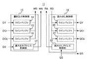
図3は、図2に示すフレームメモリ制御部11の内部構成を示すブロック図である。図3に示すように、フレームメモリ制御部11は、書き込み制御部13、および読み出し制御部18を備えている。書き込み制御部13は、ラインバッファ14,15,16、書き込みアドレス制御部17により構成され、読み出し制御部18は、ラインバッファ19,20,21、読み出しアドレス制御部22により構成される。 FIG. 3 is a block diagram showing an internal configuration of the frame
以下、画像処理部2の動作を図2および図3に基づいて詳細に説明する。
変換部3は、画像データDaを輝度データDYと色差データDcr,Dcbに変換し、記憶部4のフレームメモリ制御部11に出力する。同時に変換部3は、同期信号Saを、画像データDaの変換処理に必要な時間だけ遅延し、遅延された同期信号DSをフレームメモリ制御部11に出力する。Hereinafter, the operation of the
The
フレームメモリ制御部11に入力された輝度データDYおよび色差データDCr,DCbは、書き込み制御部13のラインバッファ14,15,16にそれぞれ入力される。書き込みアドレス制御部17は、同期信号DSに基づいて、ラインバッファ14,15,16に入力された輝度データDYおよび色差データDCr,DCbをフレームメモリ10に書き込むための書き込みアドレスWAを発生する。書き込み制御部13は、ラインバッファに記憶された輝度データDY、および色差データDCr,DCbを順次読み出し、これらのデータを書き込みアドレスWAに対応する画像データWDとしてフレームメモリ10に書き込む。 The luminance data DY and the color difference data DCr and DCb input to the frame
一方、読み出しアドレス制御部22は、出力同期信号生成部7により出力される同期信号QSに基づいて、フレームメモリ10に書き込まれた輝度データDYおよび色差信号DCr,DCbを読み出すための読み出しアドレスRAを生成して出力する。読み出しアドレスRAは、色差データDCr,DCbが輝度データDYに対し、輪郭補正部5において輪郭補正処理を行うのに必要な期間遅延して読み出されるよう生成される。フレームメモリ10は、読み出しアドレスRAに基づいて読み出されるデータRDをラインバッファ19,20,21に出力する。ラインバッファ19,20,21は、以上のようにしてタイミング調整された輝度データQYおよび色差データQCr,QCbを輪郭補正部5に出力する。 On the other hand, the read
フレームメモリ10にDRAM等を用いる場合、フレームメモリ10とフレームメモリ制御部11との間では書き込みと読み出しのいずれか一方しかできない。このため、1ライン分の輝度データ、および色差データの連続的な書き込み、あるいは読み出し動作ができないので、ラインバッファ14,15,16は、時間的に連続した輝度データDY、および色差データDCr,DCbを間欠的にフレームメモリに書き込み、ラインバッファ19,20,21は、フレームメモリ10から間欠的に読み出された輝度データQYおよび色差データQCr,QCbを時間的に連続したデータとして出力されるようタイミング調整を行う。 When a DRAM or the like is used for the
輪郭補正部5に入力された輝度データQYは垂直輪郭補正部12に入力される。垂直輪郭補正部12は、輝度データQYに対し、垂直方向の輪郭補正を行い、輪郭補正後の輝度成分のデータZYbを変換部6に出力する(垂直輪郭補正部12の輪郭補正動作については後述する)。ここで、垂直方向の輪郭補正処理を行う場合、補正後の輝度データZYbと、補正前の輝度データQYとの間には所定のライン数分の遅延が発生する。この遅延ライン数をkラインとすると、変換部6に入力される色差データQCr,QCbについてもkラインだけ遅延させなければならない。読み出しアドレス制御部22は、補正後の輝度データZYbと色差データQCr,QCbとが同期して変換部6に入力されるよう読み出しアドレスRAを生成する。すなわち、色差データQCr,QCbが輝度データZYbに対し、kライン分遅れて読み出されるよう読み出しアドレスRAを生成する。 The luminance data QY input to the
図4は、フレームメモリの書き込みおよび読み出しのタイミングを示す図である。図4(a)は、フレームメモリ10に書き込まれる輝度データDYおよび色差データDCr,DCbを示している。図4(b)は、フレームメモリ10から読み出される輝度データQYおよび色差データDCr,DCb、ならびに輪郭補正後の輝度データZYbを示している。図4において、同期信号DSおよびQSは1ライン期間を示している。 FIG. 4 is a diagram showing the timing of writing and reading of the frame memory. FIG. 4A shows luminance data DY and color difference data DCr and DCb written to the
図4(b)に示すように、フレームメモリ制御部11は、輝度データQYのkライン前の色差データQCr,QCbをフレームメモリ10から読み出す(すなわち色差データQCr,QCbを輝度データQYからkラインだけ遅れて読み出す)。これにより、変換部6は、輝度データZYbに同期した色差データQCa,QCbを出力する。このように、画像データを輝度データDYおよび色差データDCr,DCbに変換してフレームメモリに書き込み、必要なライン数の輝度データを読み出して輪郭補正処理を行い、色差データQCr,QCbについては上記処理に必要なライン数分だけ遅延して読み出すことで、色差データのタイミング調整に必要なラインメモリを削減することができる。 As shown in FIG. 4B, the frame
次に垂直輪郭補正部12の動作について説明する。図5は、垂直輪郭補正部12の内部構成を示すブロック図である。垂直輪郭補正部12は、ライン遅延A23、輪郭幅補正部24、ライン遅延B29、輪郭強調部30を備えている。輪郭幅補正部24は、輪郭幅検出部25、倍率制御量生成部26、倍率生成部27、補間演算部28により構成され、輪郭強調部30は、輪郭検出部31、強調量生成部32、強調量加算部33により構成される。 Next, the operation of the vertical
フレームメモリ制御部11により出力された輝度データQYは、ライン遅延A23に入力される。ライン遅延A23は、輪郭幅補正部24における垂直方向の輪郭幅補正処理に必要な画素数の輝度データQYaを出力する。輪郭幅補正処理が、垂直方向に配列する11個の画素を用いて行われる場合、輝度データQYaは11個の画素データで構成される。
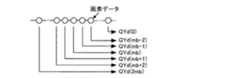
図6は、ライン遅延A23から出力される輝度データQYaのタイミングチャートであり、輝度データQYaの画素数を2ka+1とした場合について示している。ライン遅延A23から出力された輝度データQYaは輪郭幅検出部25および補間演算部28に入力される。The luminance data QY output by the frame
FIG. 6 is a timing chart of the luminance data QYa output from the line delay A23, and shows a case where the number of pixels of the luminance data QYa is 2ka + 1. The luminance data QYa output from the line delay A23 is input to the contour
図7は、輪郭幅補正部24における輪郭幅補正処理について説明するための図である。輪郭幅検出部25は、輝度データQYaの大きさが垂直方向に所定期間連続的に変化している部分を輪郭として検知し、当該輪郭の幅(輪郭幅)Wa、および輪郭幅における所定の位置を基準位置PMとして検出する。図7(a)は輪郭幅検出部25により検出される輪郭幅Waおよび基準位置PMを示している。検出された輪郭幅Waおよび基準位置PMは倍率制御量生成部26に入力される。 FIG. 7 is a diagram for explaining the contour width correction processing in the contour
倍率制御量生成部26は、検出された輪郭幅Waと輪郭基準位置Waに基づいて、輪郭幅補正に用いる倍率制御量ZCを出力する。図7(b)は、倍率制御量を示す図である。図7(b)に示すように、倍率制御量ZCは輪郭前部bおよび輪郭後部cで正、輪郭中央部cで負、他の部分ではゼロとなり、輪郭部における総和が0となるよう生成される。倍率制御量ZCは倍率生成部27に送られる。 The magnification
倍率生成部27は、予め設定される画像全体の変換倍率である基準変換倍率Z0に倍率制御量ZCを重畳して変換倍率Zを発生する。図7(c)は、変換倍率Zを示す図である。変換倍率Zは、輪郭前部bおよび輪郭後部dでは基準変換倍率Z0よりも大きく、輪郭中央部cでは基準変換倍率Z0よりも小さくなり、変換倍率Zの平均は基準変換倍率Z0と等しくなる。この基準倍率をZ0>1とした場合、輪郭幅補正処理とともに画素数を増やす拡大処理が行われ、Z0<1とした場合は画素数を減らす縮小処理が行われる。また、基準変換倍率をZ0=1とした場合、輪郭補正処理のみが行われる。 The
補間演算部28は、変換倍率Zに基づいて輝度データQYaに対し補間演算処理を行う。補間演算処理の際、変換倍率Zが基準変換倍率Z0よりも大きい輪郭前部bおよび輪郭後部dでは補間密度が高くなり、変換倍率Zが基準倍率Z0よりも小さい輪郭中央部cでは補間密度が低くなる。つまり、輪郭前部bおよび輪郭後部dでは画素数を相対的に増やす拡大処理が行われ、輪郭中央部cでは画素数を相対的に減らす縮小処理が行われる。図7(d)は、図7(c)に示す変換倍率Zに基づいて画素数変換、および輪郭幅補正を行った輝度データZYaを示す図である。輪郭中央部cでは画像を縮小し、輪郭前部bおよび輪郭後部dでは画像を拡大することにより、図7(d)に示すように輪郭幅を縮小し、輪郭部における輝度を急峻に変化させ、画像の鮮鋭度を向上することができる。 The
ここで、輪郭幅Waに基づいて生成される倍率制御量ZCは、期間b,c,dにおける総和がゼロとなるように生成される。つまり、図7(b)において斜線で示した部分の面積をそれぞれSb,Sc,Sdとすると、Sb+Sd=Scとなるように生成される。このため、変換倍率Zは局部的に変動するが、画像全体での変換倍率Zは、基準変換倍率Z0と等しくなる。このように、変換倍率Zの総和が基準変換0と等しくなるよう倍率制御量ZCを生成することにより、輪郭部における画像のずれを生じることなく輪郭幅を補正することができる。 Here, the magnification control amount ZC generated based on the contour width Wa is generated such that the sum in the periods b, c, and d becomes zero. That is, if the areas of the hatched portions in FIG. 7B are Sb, Sc, and Sd, respectively, they are generated so that Sb + Sd = Sc. For this reason, although the conversion magnification Z varies locally, the conversion magnification Z in the entire image is equal to the reference conversion magnification Z0. In this way, by generating the magnification control amount ZC so that the total sum of the conversion magnifications Z becomes equal to the
なお、輪郭幅Waの補正量、すなわち変換後の輪郭幅Wbは、図7(c)に示す変換倍率Zの大きさ、具体的には図7(b)に示す変換倍率制御量ZCの期間cにおける面積Scの大きさによって任意に設定することができる。よって、当該面積Scの大きさを調整することにより、変換後の画像を所望の鮮鋭度にすることができる。 The correction amount of the contour width Wa, that is, the converted contour width Wb, is the size of the conversion magnification Z shown in FIG. 7C, specifically, the period of the conversion magnification control amount ZC shown in FIG. It can be arbitrarily set depending on the size of the area Sc in c. Therefore, by adjusting the size of the area Sc, the converted image can have a desired sharpness.
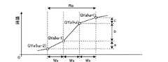
図8は、輝度データQYaと輪郭幅Waとの関係について説明するための図である。QYa(ka−2),QYa(ka−1),QYa(ka),QYa(ka+1)は、輝度データQYaの一部の画素データを示している。図8においてWsは、各画素データの間隔(垂直方向のサンプリング周期)を示している。図8に示すように、画素データQYa(ka−2)とQYa(ka−1)との差分量をa、画素データQYa(ka−1)とQYa(ka)との差分量をb、画素データQYa(ka)とQYa(ka+1)との差分量をcとする。すなわち、a=QYa(ka−1)−QYa(ka−2)、b=QYa(ka)−QYa(ka−1)、c=QYa(ka+1)−QYa(ka)とする。ここで、a,b,cは、それぞれ輪郭前部、輪郭中央部、輪郭後部の画素データの変化量を示している。 FIG. 8 is a diagram for explaining the relationship between the luminance data QYa and the contour width Wa. QYa (ka-2), QYa (ka-1), QYa (ka), and QYa (ka + 1) indicate partial pixel data of the luminance data QYa. In FIG. 8, Ws indicates the interval (vertical sampling period) of each pixel data. As shown in FIG. 8, the difference amount between the pixel data QYa (ka-2) and QYa (ka-1) is a, the difference amount between the pixel data QYa (ka-1) and QYa (ka) is b, and the pixel Let c be the difference between the data QYa (ka) and QYa (ka + 1). That is, a = QYa (ka-1) -QYa (ka-2), b = QYa (ka) -QYa (ka-1), and c = QYa (ka + 1) -QYa (ka). Here, a, b, and c indicate the amount of change in pixel data at the front part of the contour, the center part of the contour, and the rear part of the contour, respectively.
輪郭幅検出部25は、輝度データが単調増加あるいは単調減少しており、かつ輪郭前部および後部が輪郭中央部に比べて平坦であるような部分を、輪郭として検出するものとする。このときの条件は、a,b,cそれぞれの正負の符号が同じかまたはゼロであり、かつaの絶対値とcの絶対値の両方がbの絶対値より小さいことである。つまり、以下に示す式(1a)および式(1b)を同時に満たす場合、図8に示す画素データQYa(ka−2),QYa(Ka),QYa(Ka+1)の3画素を輪郭とみなし、この期間を輪郭幅Waとして出力する。
a≧0,b≧0,c≧0、またはa≦0,b≦0,c≦0 …(1a)
|b|>|a|,|b|>|c| …(1b)
このとき、輪郭幅Wa=3×Wsである。The contour
a ≧ 0, b ≧ 0, c ≧ 0, or a ≦ 0, b ≦ 0, c ≦ 0 (1a)
| B |> | a |, | b |> | c | (1b)
At this time, the contour width Wa = 3 × Ws.
図6に示すように、輪郭幅検出部25には2ka+1個の画素データが入力されるので、2ka+1画素までの輪郭、2ka×Wsまでの輪郭幅を検出できる。よって、倍率制御量生成部26において、検出された輪郭幅に応じて異なる変換倍率制御量を与えることにより、画像の鮮鋭度を輪郭幅に応じて調整することができる。また、輪郭の振幅ではなく輪郭幅に応じて変換倍率制御量を決定するので、輝度変化が緩やかな輪郭についても鮮鋭度を向上させることができる。
なお、輪郭幅の検出は、1画素おき(2Ws間隔)に抽出される画素データを用いて行ってもよい。As shown in FIG. 6, since 2 ka + 1 pixel data is input to the contour
The contour width may be detected using pixel data extracted every other pixel (2 Ws interval).
補間演算部28により出力される輪郭幅補正後の輝度データZYaは、ライン遅延B29に送られる。ライン遅延B29は、輪郭強調部30における輪郭強調処理に必要な画素数の輝度データQYbを出力する。輪郭強調処理が5個の画素を用いて行われる場合、輝度データQYbは5画素分の輝度データで構成される。図9はライン遅延B29から出力される輝度データQYbのタイミングチャートであり、輝度データQYbの画素数を2kb+1とした場合について示している。ライン遅延B29から出力された輝度データQYbは、輪郭検出部31、および強調量加算部33に入力される。 The contour-corrected luminance data ZYa output by the
輪郭検出部31は、輝度データYQbに対し2次微分等の微分演算を行うことにより、補正後の輪郭幅Wbにおける輝度の変化量を検出し、検出結果を輪郭検出データRとして強調量生成部32に出力する。強調量生成部32は、輪郭検出データRに基づいて輝度データQYbの輪郭を強調するための強調量SHを生成し、強調量加算部33に出力する。強調量加算部33は、輝度データQYbに強調量SHを加算することにより画像データQYbの輪郭を強調する。 The
図10は、輪郭強調部30における輪郭強調処理について説明するための図である。図10(a)は輪郭幅補正前の輝度データQYaを示し、図10(b)は輪郭幅補正後の輝度データZYaを示す。図10(c)は、(b)に示す輝度データZYaに基づいて生成される強調量SHを示し、図10(d)は、(c)に示す強調量SHを(b)に示す輝度データZYaに加算して得られる輪郭強調後の輝度データZYbを示している。 FIG. 10 is a diagram for explaining the contour emphasis processing in the
図10(d)に示すように、輪郭強調部30は輪郭幅補正部24により幅が縮小された輪郭部の前後に(c)に示す強調量SH、すなわちアンダーシュートおよびオーバーシュートを付加して輪郭強調処理を行う。ここで、輪郭幅の補正を行わずに輪郭強調処理を行おうとすると、輝度変化が緩やかな輪郭についてはアンダーシュートおよびオーバーシュートの生成に用いる微分回路の通過帯域を低く設定しなければならない。通過帯域の低い微分回路を用いて生成されるアンダーシュートおよびオーバーシュートは幅が広い形状となるため、輪郭の鮮鋭度を十分に高めることができない。 As shown in FIG. 10D, the
本発明に係る画像処理装置においては、図10(a)および図10(b)に示すように、輝度データQYaの輪郭幅Waを縮小して輪郭部における輝度変化を急峻にする輪郭幅補正処理を行い、輪郭補正された輝度データZYaに基づいて図10(c)に示すアンダーシュートおよびオーバーシュート(強調量SH)を生成し、この強調量SHを輪郭幅補正された輝度データZYaに付加するので、幅の広いぼやけた輪郭部を適切に補正し、鮮鋭度の高い画像を得ることができる。 In the image processing apparatus according to the present invention, as shown in FIGS. 10 (a) and 10 (b), a contour width correction process for reducing the contour width Wa of the luminance data QYa to sharpen the luminance change in the contour portion. 10 is generated based on the brightness data ZYa whose contour is corrected, and the undershoot and overshoot (enhancement amount SH) shown in FIG. 10C are generated, and this enhancement amount SH is added to the brightness data ZYa whose contour width is corrected. Therefore, it is possible to appropriately correct a wide blurred outline and obtain an image with high sharpness.
なお、輪郭強調部30は、ノイズ成分に対しては強調処理を行わないよう構成してもよく、さらに、ノイズ成分を低減するノイズリダクション機能を設けてもよい。このような処理は、強調量生成部32において輪郭検出部31の輪郭検出データRに対して非線形処理を行うことで実現することができる。
また、輪郭検出部31において求められる輪郭検出データRは、微分演算以外にパターンマッチングや他の演算によって検出してもよい。Note that the
Further, the contour detection data R obtained by the
図11は、画像処理部2の他の構成を示すブロック図である。図11に示す画像処理部2は、垂直輪郭補正部12の後段に水平輪郭補正部34を備えている。水平輪郭補正部34は、垂直輪郭補正部12により出力される輝度データZYbを入力し、水平方向の輪郭補正処理を行う。 FIG. 11 is a block diagram illustrating another configuration of the
図12は、水平輪郭補正部34の内部構成を示すブロック図である。輪郭幅補正部24および輪郭強調部30の構成および動作は、図5に示す垂直輪郭補正部12と同様である。
画素遅延A35は、垂直輪郭補正部12から順次出力される輝度データZYbを入力し、輪郭幅補正部24における水平方向の輪郭幅補正処理に必要な画素数の輝度データQYcを出力する。図13は、画素遅延A35から出力される輝度データQYcを示す模式図であり、輝度データQYcの画素数を2ma+1とした場合について示している。図13に示すように、画素遅延A35は水平方向に配列する複数の画素データからなる輝度データQYcを出力する。輪郭幅補正が、水平方向に配列する11個の画素を用いて行われる場合、輝度データQYcは11個の画素データで構成される。FIG. 12 is a block diagram showing the internal configuration of the horizontal
The pixel delay A35 receives the luminance data ZYb sequentially output from the vertical
画素遅延A35から出力された2ma+1画素分の輝度データQYcは、輪郭幅補正部24に送られる。輪郭幅補正部24は、水平方向の輝度データQYcに対し、先述した垂直方向における輪郭幅補正処理と同様の処理を行うことにより、水平方向の輪郭幅が補正された輝度データZYcを出力する。 The luminance data QYc for 2ma + 1 pixel output from the pixel delay A35 is sent to the contour
輪郭幅補正部24により出力される輪郭幅補正後の輝度データZYcは、画素遅延B36に入力される。画素遅延B36は、輪郭強調部30における輪郭強調処理に必要な画素数の輝度データQYdを出力する。図14は、画素遅延B36から出力されるQYdのデータを示す模式図であり、輝度データZYcの画素数を2mb+1とした場合について示している。図14に示すように、画素遅延B36は水平方向に配列する複数の画素データからなる輝度データQYdを出力する。輪郭強調が、水平方向に配列する5個の画素を用いて行われる場合、輝度データQYdは5個の画素データで構成される。 The brightness data ZYc after the contour width correction output by the contour
画素遅延B36から出力された2mb+1画素分の輝度データQYdは、輪郭強調部30に送られる。輪郭強調部30は、水平方向の輝度データQYdに対し、先述した垂直方向における輪郭強調処理と同様の処理を行うことにより、水平方向に輪郭強調された輝度データZYdを出力する。 The luminance data QYd for 2 mb + 1 pixel output from the pixel delay B36 is sent to the
水平輪郭補正部34により出力される輪郭補正後の輝度データZYeは、変換部6に入力される。フレームメモリ制御部11は、色差データQCr,QCbと輪郭補正後の輝度データZYeが同期して変換部6に入力されるよう、輝度データQCr,Qcbを輪郭補正に要する期間、すなわち輝度データQYが垂直輪郭補正部12に入力されてから垂直方向の輪郭補正後の輝度データZYbが出力されるまでに要する所定ライン数分の期間、および水平輪郭補正部34に垂直輪郭補正後の輝度データZYbが入力されてから水平輪郭補正後の輝度データZYdが出力されるまでに要する所定クロック数分の期間だけ遅延して出力する。具体的には、色差データQCr,QCbが輝度データZYdに対して上記期間だけ遅延してフレームメモリ6から出力されるよう読み出しアドレスRAを生成する。これにより、輝度データQCr,QCbを遅延するためのラインメモリを削減することができる。
なお、水平方向の輪郭補正を行った後に垂直方向の輪郭補正を行ってもよく、また、垂直方向と水平方向の輪郭補正を同時に実施してもよい。Brightness data ZYe after contour correction output by the horizontal
Note that the contour correction in the vertical direction may be performed after performing the contour correction in the horizontal direction, or the contour correction in the vertical direction and the horizontal direction may be performed simultaneously.
以上において説明した本発明に係る画像処理装置は、画像の垂直方向あるいは水平方向の輪郭補正を行う際、まず輪郭幅を補正し、幅が補正された輪郭にアンダーシュート、オーバーシュートを付加するので、輝度変化の緩やかな輪郭についても輪郭幅を縮小して輝度変化を急峻にし、適切な幅のアンダーシュート、オーバーシュートを付加することが可能であり、輝度変化の異なる様々な輪郭に対し適切な補正処理を行うことにより画像の鮮鋭度を過不足なく向上することができる。
また、輪郭幅を補正する際、輪郭の振幅ではなく幅の大きさに基づいて補正量を決定するので、輝度変化の緩やかな輪郭についても鮮鋭度を向上させ、適切な輪郭強調処理を行うことができる。The image processing apparatus according to the present invention described above corrects the contour width first when performing contour correction in the vertical or horizontal direction of the image, and adds undershoot and overshoot to the contour whose width is corrected. It is also possible to reduce the contour width for sharp contours with a gradual change in brightness to make the brightness change steep and to add undershoot and overshoot with appropriate widths. By performing the correction process, the sharpness of the image can be improved without excess or deficiency.
Also, when correcting the contour width, the amount of correction is determined based on the width of the contour, not the amplitude of the contour, so sharpness is improved even for contours with gradual changes in brightness, and appropriate contour enhancement processing is performed. Can do.
また、輪郭補正を行う際、輝度データQYと色差データQCr,QCbをフレームメモリに書き込み、当該フレームメモリから輝度データを読み出して輪郭補正処理を行い、色差データQCr,QCbについては輝度データQYに対して上記の輪郭補正処理を行うのに要する期間遅らせて読み出すので、色差データQCr,QCbのタイミング調整に必要な遅延素子を設けることなく輝度データに対し輪郭補正処理を実施することができる。 Further, when performing contour correction, luminance data QY and color difference data QCr, QCb are written to the frame memory, luminance data is read from the frame memory, and contour correction processing is performed. For the color difference data QCr, QCb, the luminance data QY Therefore, the contour correction processing can be performed on the luminance data without providing a delay element necessary for timing adjustment of the color difference data QCr and QCb.
実施の形態2.
図15は、本発明に係る画像処理装置の他の実施形態を示すブロック図である。図15に示す画像表示装置は、変換部3と記憶部4との間に画素数変換部38を備えている。他の構成については、実施の形態1において説明した画像処理装置(図1参照)と同様である。
FIG. 15 is a block diagram showing another embodiment of the image processing apparatus according to the present invention. The image display apparatus illustrated in FIG. 15 includes a pixel
画素数変換部38は、変換部3により出力される輝度データDYおよび色差データDCr,DCbからなる画像データに対し、画素数の変換処理、すなわち画像の拡大あるいは縮小処理を行う。図16は、画素数変換部38における画像の拡大および縮小処理の例を示す図であり、(a)は拡大処理、(b)は縮小処理、(c)は部分拡大処理をそれぞれ示している。
図16(a)および(c)に示すように画像の拡大処理を行った場合、以下に述べるように輪郭部が不鮮明になるという問題が生じる。図17は画像の拡大処理を行った場合の輪郭部分の輝度変化を示す図であり、図17(a)は入力画像、(b)は拡大画像における輪郭部分の輝度変化をそれぞれ示している。図17(b)に示すように、拡大処理を行った場合、輪郭幅が広がることにより輪郭部分がぼやけた画像となる。The pixel
When the image enlargement process is performed as shown in FIGS. 16A and 16C, there arises a problem that the contour portion becomes unclear as described below. FIGS. 17A and 17B are diagrams showing the luminance change of the contour portion when the image enlargement processing is performed. FIG. 17A shows the input image, and FIG. 17B shows the luminance change of the contour portion in the enlarged image. As shown in FIG. 17B, when the enlargement process is performed, the contour portion becomes an image with a blurred contour portion due to the expansion of the contour width.
拡大処理あるいは縮小処理を行った画像データは記憶部4に一時的に記憶され、所定のタイミングで読み出され、輪郭補正部5に送られる。輪郭補正部5は、記憶部4から出力される輝度データDYに対し、実施の形態1において述べた輪郭補正処理を行うことにより、拡大処理によりぼやけた輪郭を補正する。 The image data subjected to the enlargement process or the reduction process is temporarily stored in the storage unit 4, read at a predetermined timing, and sent to the
本実施の形態に示す画像処理装置によれば、画像の拡大処理により幅が広がった輪郭部を実施の形態1において説明した方法により補正するので、鮮鋭度を低下させることなく任意の倍率で画像を拡大することができる。また、実施の形態1と同様に、拡大処理により幅が広がった輪郭に対し適切な幅のアンダーシュート、オーバーシュートを付加することが可能であり、拡大画像の鮮鋭度を過不足なく向上することができる。
なお、画像の拡大あるいは縮小処理を行った後に、当該画像を構成するデータ輝度データと色差データからなる画像データに変換するよう構成してもよい。According to the image processing apparatus shown in the present embodiment, since the contour portion widened by the image enlargement process is corrected by the method described in the first embodiment, the image can be obtained at any magnification without reducing the sharpness. Can be enlarged. In addition, as in the first embodiment, it is possible to add undershoot and overshoot with appropriate widths to the contour widened by the enlargement process, and improve the sharpness of the enlarged image without excess or deficiency. Can do.
In addition, after performing an enlargement or reduction process of an image, the image data may be converted to image data including data luminance data and color difference data.
実施の形態3.
図18は本発明に係る画像処理装置の他の実施形態を示すブロック図である。図18に示す画像処理装置は、画像信号発生部39、および合成部41をさらに備えている。画像信号発生部39は、受信部1から出力される同期信号Saに基づく所定のタイミングで画像データDaに合成される画像データDbを発生し、合成部41に出力する。合成部4は画像データDaに画像データDbを合成する。ここでは、画像データDbは文字情報を表すものとする。
FIG. 18 is a block diagram showing another embodiment of the image processing apparatus according to the present invention. The image processing apparatus shown in FIG. 18 further includes an image
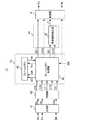
図19は、画像処理部40のより詳細な構成を示すブロック図である。合成部41は、画像データDaと画像データDbのいずれかを画素毎に選択するか、あるいは、画像データDaと画像データDbとを用いた演算により2つの画像を合成し、合成画像データDcを生成する。同時に合成部41は、合成画像データDcの同期信号Sc、および合成画像データDcのうち輪郭補正処理を行わない領域を指定する画像処理制御信号Dbsを出力する。変換部42は、実施の形態1と同様に合成画像データDcを輝度データDYおよび色差データDCr,DCbに変換し、画像処理制御信号DYSおよび同期信号DSとともにフレームメモリ制御部46に出力する。 FIG. 19 is a block diagram showing a more detailed configuration of the
フレームメモリ制御部46は、画像処理制御信号DYSを輝度データDYおよび色差データDCr,DCbとともにフレームメモリ45に一時的に記憶する。フレームメモリ制御部46は、フレームメモリ45に格納された輝度データDYと、色差データDCr,DCbとを図4に示すタイミングで読み出し、タイミング調整された輝度データQY,色差データQCr,QCbを出力する。また、フレームメモリ制御部46は、フレームメモリ45に一時的に記憶された画像処理制御信号DYSを垂直輪郭補正部47における輪郭幅補正処理に要する期間だけ遅延して読み出すことにより、タイミング調整された画像処理制御信号QYSを出力する。フレームメモリ制御部46により出力される輝度データQY、および画像処理制御信号QYSは垂直輪郭補正部47に入力される。 The frame
図20は、垂直輪郭補正部47の内部構成を示すブロック図である。図20に示す垂直輪郭補正部47は、選択部49,52、およびライン遅延Cをさらに備えている。なお、他の構成は実施の形態1と同様である。
補間演算部28は、ライン遅延A23から出力される垂直方向の輝度データQYaに対し垂直方向の輪郭幅補正処理を行い、補正後の輝度データZYaを出力する。輪郭幅補正後の輝度データZYaは、補正前の輝度データQYa、および画像処理制御信号QYSとともに選択部49に送られる。選択部49は、画像処理制御信号QYSに基づいて輪郭幅補正された輝度データZYaと補正前の輝度データQYaのいずれかを画素毎に選択し、ライン遅延B29に出力する。FIG. 20 is a block diagram showing the internal configuration of the vertical
The
ライン遅延B29は、輪郭強調部51における輪郭強調処理に必要な画素数の輝度データQYbを輪郭検出部31、および強調量加算部33に出力する。また、ライン遅延C50は、画像処理制御信号QYSを輪郭強調部51における処理に必要なライン数分の期間遅延し、遅延された画像処理制御信号QYSbを選択部52に出力する。
強調量加算部33は、ライン遅延B29から出力される垂直方向の輝度データQYbに輪郭強調処理を行った輝度データZYbを出力する。輪郭強調後の輝度データZYbは、輪郭強調前の輝度データQYb、およびライン遅延Cにより遅延された画像処理制御信号QYSbとともに選択部52に送られる。選択部52は、画像処理制御信号QYSbに基づいて輪郭補正処理された輝度データZYbと補正前の輝度データQYbのいずれかを画素毎に選択し、選択した輝度データZYを出力する。The line delay B29 outputs luminance data QYb of the number of pixels necessary for the contour emphasizing process in the
The enhancement
図21は、本実施の形態に係る画像処理装置の動作について説明するための図であり、図21(a)は画像データDa、(b)は画像データDb、(c)は合成画像データDc、(d)(e)は画像処理制御信号Dbsの一例をそれぞれ示している。図21(a)に示す画像データDaは風景画像を表し、図21(b)に示す画像データDbは文字情報を表しており、これらの画像データを合成することにより図21(c)に示す風景画像に文字情報が重畳された合成画像データDcが生成される。図4(d)に示す画像処理制御信号QYSによれば、白で示された矩形領域において輪郭補正処理は行われず、当該領域以外の部分のみ輪郭補正処理が行われる。また、図4(e)に示す画像処理制御信号によれば、文字情報部分において輪郭補正処理は行われず、文字情報以外の領域、すなわち風景画像部分において輪郭補正処理が行われる。 FIG. 21 is a diagram for explaining the operation of the image processing apparatus according to the present embodiment. FIG. 21A shows image data Da, FIG. 21B shows image data Db, and FIG. 21C shows composite image data Dc. , (D) and (e) respectively show examples of the image processing control signal Dbs. The image data Da shown in FIG. 21A represents a landscape image, and the image data Db shown in FIG. 21B represents character information. By combining these image data, the image data shown in FIG. Composite image data Dc in which character information is superimposed on a landscape image is generated. According to the image processing control signal QYS shown in FIG. 4D, the contour correction process is not performed on the rectangular area shown in white, and the contour correction process is performed only on the part other than the area. Further, according to the image processing control signal shown in FIG. 4E, the contour correction processing is not performed on the character information portion, but the contour correction processing is performed on the region other than the character information, that is, the landscape image portion.
輪郭幅補正部48および輪郭強調部51の選択部49,52において、図21(d),(e)に示すような画像処理制御信号QYSに基づいて輪郭補正前の輝度データと補正後の輝度データとを選択することにより、不要な補正により文字情報やその周辺の輪郭が不自然になるのを防ぐことができる。 In the
以上において説明したように、本実施の形態による画像処理装置においては、画像データに文字情報や図形情報といった任意の画像を合成し、合成画像に輪郭補正処理を行うとともに合成画像における特定の領域を指定する画像処理制御信号を発生し、補正後の合成画像と補正前の合成画像を画像処理制御信号に基づいて画素毎に選択して出力するので、必要な部分のみについて輪郭補正処理を行うことが可能である。 As described above, in the image processing apparatus according to the present embodiment, an arbitrary image such as character information or graphic information is synthesized with image data, a contour correction process is performed on the synthesized image, and a specific area in the synthesized image is displayed. Generate the specified image processing control signal, and select and output the corrected composite image and the uncorrected composite image for each pixel based on the image processing control signal. Is possible.
1 受信部、 2 画像処理部、 3 変換部、 4 記憶部、 5 輪郭補正部、 6 変換部、 7 出力同期信号生成部、 8 送信部、 9 表示部、 10 フレームメモリ、 11 フレームメモリ制御部、 12 垂直輪郭補正部
DESCRIPTION OF
Claims (11)
Translated fromJapanese上記倍率制御量に基づいて上記画像データに対し補間演算処理を行うことにより、上記輪郭幅を補正する輪郭幅補正手段と、
上記輪郭幅を補正した画像データの高域成分を検出し、検出された高域成分に基づいて上記画像データの輪郭部を強調するための強調量を算出する強調量算出手段と、
上記輪郭幅を補正した画像データに上記強調量を付加することにより、上記画像データの輪郭部を強調する輪郭強調手段とを備えることを特徴とする画像処理装置。A magnification control means for detecting a contour portion of the image data and generating a magnification control amount based on the contour width of the detected contour portion;
Contour width correcting means for correcting the contour width by performing an interpolation calculation process on the image data based on the magnification control amount;
An enhancement amount calculating means for detecting a high frequency component of the image data with the contour width corrected, and calculating an enhancement amount for enhancing the contour portion of the image data based on the detected high frequency component;
An image processing apparatus comprising: an edge emphasizing unit that enhances an edge portion of the image data by adding the enhancement amount to the image data in which the edge width is corrected.
上記輪郭幅補正手段は、上記変換倍率に基づいて補間演算処理を行うことを特徴とする請求項1に記載の画像処理装置。The magnification control means generates the magnification control amount so that the contour front is positive, the contour center is negative, the contour rear is positive, and the total sum is 0. Generate a conversion magnification by superimposing on the standard conversion magnification indicating the reduction ratio,
The image processing apparatus according to claim 1, wherein the contour width correcting unit performs an interpolation calculation process based on the conversion magnification.
上記画像生成手段により生成された画像を上記画像データに合成した合成画像データを出力する画像合成手段と、
上記合成画像データの所定の領域を指定する画像処理制御信号を生成する手段とをさらに備え、
上記輪郭幅補正手段、および上記輪郭強調手段は、上記画像処理制御信号により指定された領域についてのみ輪郭幅の補正、および輪郭部の強調をそれぞれ行うことを特徴とする請求項1または2に記載の画像処理装置。Image generating means for generating an image to be combined with the image data;
Image combining means for outputting combined image data obtained by combining the image generated by the image generating means with the image data;
Means for generating an image processing control signal for designating a predetermined region of the composite image data,
3. The contour width correcting means and the contour emphasizing means respectively perform contour width correction and contour portion enhancement only for a region designated by the image processing control signal. Image processing apparatus.
上記倍率制御量に基づいて上記画像データに対し補間演算処理を行うことにより、上記輪郭幅を補正する工程と、
上記輪郭幅を補正した画像データの高域成分を検出し、検出された高域成分に基づいて上記画像データの輪郭部を強調するための強調量を算出する工程と、
上記輪郭幅を補正した画像データに上記強調量を付加することにより、上記画像データの輪郭部を強調する工程とを備えることを特徴とする画像処理方法。Detecting a contour portion of the image data, and generating a magnification control amount based on the contour width of the detected contour portion;
Correcting the contour width by performing an interpolation calculation process on the image data based on the magnification control amount;
Detecting a high frequency component of the image data with the contour width corrected, and calculating an enhancement amount for emphasizing a contour portion of the image data based on the detected high frequency component;
And a step of emphasizing a contour portion of the image data by adding the enhancement amount to the image data with the contour width corrected.
上記変換倍率に基づいて補間演算処理を行うことを特徴とする請求項4に記載の画像処理方法。The magnification control amount is generated so that the contour front is positive, the contour center is negative, the contour rear is positive, and the total sum is 0. The magnification control amount is a reference indicating the enlargement or reduction ratio of the image data. The method further includes a step of generating a conversion magnification by superimposing on the conversion magnification,
5. The image processing method according to claim 4, wherein an interpolation calculation process is performed based on the conversion magnification.
上記画像を上記画像データに合成した合成画像データを出力する工程と、
上記合成画像データの所定の領域を指定する画像処理制御信号を生成する工程とをさらに備え、
上記画像処理制御信号により指定された領域についてのみ輪郭幅の補正、および輪郭部の強調をそれぞれ行うことを特徴とする請求項4または5に記載の画像処理方法。Generating an image to be combined with the image data;
Outputting combined image data obtained by combining the image with the image data;
Generating an image processing control signal that designates a predetermined region of the composite image data,
6. The image processing method according to claim 4, wherein the contour width is corrected and the contour portion is enhanced only for the region designated by the image processing control signal.
上記輝度データおよび色差データをフレームメモリに書き込み、当該フレームメモリに書き込まれた上記輝度データおよび色差データを所定のタイミングで読み出すフレームメモリ制御手段と、
上記フレームメモリから読み出される上記輝度データから、垂直方向に配列する複数の画素データを抽出する手段と、
上記垂直方向に配列する複数の画素データから輪郭部を検出し、検出された輪郭部の輪郭幅に基づいて垂直方向の倍率制御量を生成する倍率制御手段と、
上記垂直方向の倍率制御量に基づいて上記輝度データに対し補間演算処理を行うことにより、垂直方向の輪郭幅を補正する輪郭幅補正手段とを備え、
上記フレームメモリ制御手段は、上記色差データを上記輝度データに対し、少なくとも上記垂直方向の輪郭幅の補正に要する期間遅延して読み出すことを特徴とする画像処理装置。Conversion means for receiving image data and converting the image data into luminance data and color difference data;
Frame memory control means for writing the luminance data and color difference data to a frame memory, and reading the luminance data and color difference data written to the frame memory at a predetermined timing;
Means for extracting a plurality of pixel data arranged in a vertical direction from the luminance data read from the frame memory;
Magnification control means for detecting a contour portion from a plurality of pixel data arranged in the vertical direction and generating a vertical magnification control amount based on the contour width of the detected contour portion;
Contour width correcting means for correcting the contour width in the vertical direction by performing interpolation calculation processing on the luminance data based on the vertical magnification control amount,
The image processing apparatus according to claim 1, wherein the frame memory control means reads the color difference data with a delay of at least a period required for correcting the contour width in the vertical direction with respect to the luminance data.
上記垂直方向の輪郭幅を補正した輝度データに上記強調量を付加することにより、上記輝度データの垂直方向の輪郭部を強調する輪郭強調手段とをさらに備え、
上記フレームメモリ制御手段は、上記色差データを上記輝度データに対し、上記垂直方向の輪郭幅の補正および輪郭部の強調に要する期間遅延して読み出すことを特徴とする請求項7に記載の画像処理装置。Emphasis amount calculation for detecting a high frequency component of luminance data with the contour width in the vertical direction corrected, and calculating an enhancement amount for emphasizing the vertical contour portion of the luminance data based on the detected high frequency component Means,
Contour emphasizing means for emphasizing a vertical contour portion of the luminance data by adding the enhancement amount to the luminance data in which the vertical contour width is corrected;
8. The image processing according to claim 7, wherein the frame memory control means reads the color difference data with respect to the luminance data with a delay required for correcting the contour width in the vertical direction and emphasizing the contour portion. apparatus.
上記水平方向に配列する複数の画素データから輪郭部を検出し、検出された輪郭部の輪郭幅に基づいて水平方向の倍率制御量を生成する倍率制御手段と、
上記水平方向に配列する複数の画素データから輪郭部を検出し、検出された輪郭部の輪郭幅に基づいて水平方向の倍率制御量を生成する倍率制御手段と、
上記水平方向の倍率制御量に基づいて上記輝度データに対し補間演算処理を行うことにより、水平方向の輪郭幅を補正する輪郭幅補正手段とを備えることを特徴とする請求項7または8に記載の画像処理装置。Means for extracting a plurality of pixel data arranged in a horizontal direction from the luminance data read from the frame memory;
Magnification control means for detecting a contour portion from a plurality of pixel data arranged in the horizontal direction and generating a horizontal magnification control amount based on the contour width of the detected contour portion;
Magnification control means for detecting a contour portion from a plurality of pixel data arranged in the horizontal direction and generating a horizontal magnification control amount based on the contour width of the detected contour portion;
9. A contour width correcting unit that corrects a horizontal contour width by performing an interpolation calculation process on the luminance data based on the horizontal magnification control amount. Image processing apparatus.
上記水平方向の輪郭幅を補正した輝度データに上記強調量を付加することにより、上記輝度データの水平方向の輪郭部を強調する輪郭強調手段とをさらに備えることを特徴とする請求項9に記載の画像処理装置。Emphasis amount calculation for detecting a high frequency component of luminance data in which the horizontal contour width is corrected and calculating an enhancement amount for emphasizing the horizontal contour portion of the luminance data based on the detected high frequency component Means,
The contour emphasizing means for emphasizing a horizontal contour portion of the luminance data by adding the enhancement amount to the luminance data in which the horizontal contour width is corrected. Image processing apparatus.
The image display apparatus provided with the image processing apparatus of any one of Claims 1-3 and 7-10.
Priority Applications (4)
| Application Number | Priority Date | Filing Date | Title |
|---|---|---|---|
| JP2004252212AJP2006074155A (en) | 2004-08-31 | 2004-08-31 | Image processing apparatus, image processing method, and image display apparatus |
| US11/597,408US20080043145A1 (en) | 2004-08-31 | 2004-10-19 | Image Processing Apparatus, Image Processing Method, and Image Display Apparatus |
| PCT/JP2004/015397WO2006025121A1 (en) | 2004-08-31 | 2004-10-19 | Image processing apparatus, image processing method and image displaying apparatus |
| TW093132676ATWI249358B (en) | 2004-08-31 | 2004-10-28 | Image processing device, image processing method and image display device |
Applications Claiming Priority (1)
| Application Number | Priority Date | Filing Date | Title |
|---|---|---|---|
| JP2004252212AJP2006074155A (en) | 2004-08-31 | 2004-08-31 | Image processing apparatus, image processing method, and image display apparatus |
Publications (2)
| Publication Number | Publication Date |
|---|---|
| JP2006074155Atrue JP2006074155A (en) | 2006-03-16 |
| JP2006074155A5 JP2006074155A5 (en) | 2006-09-14 |
Family
ID=35999784
Family Applications (1)
| Application Number | Title | Priority Date | Filing Date |
|---|---|---|---|
| JP2004252212APendingJP2006074155A (en) | 2004-08-31 | 2004-08-31 | Image processing apparatus, image processing method, and image display apparatus |
Country Status (4)
| Country | Link |
|---|---|
| US (1) | US20080043145A1 (en) |
| JP (1) | JP2006074155A (en) |
| TW (1) | TWI249358B (en) |
| WO (1) | WO2006025121A1 (en) |
Cited By (6)
| Publication number | Priority date | Publication date | Assignee | Title |
|---|---|---|---|---|
| JP2008078931A (en)* | 2006-09-20 | 2008-04-03 | Sony Corp | Video processing equipment and video processing method |
| KR100836010B1 (en) | 2007-05-03 | 2008-06-09 | 한국과학기술원 | Contour Reinforcement Device and Method for Increasing Frame Rate of Hold Type Display |
| JP2008259097A (en)* | 2007-04-09 | 2008-10-23 | Mitsubishi Electric Corp | Video signal processing circuit and video display device |
| WO2009022675A1 (en)* | 2007-08-14 | 2009-02-19 | Ricoh Company, Ltd. | Image processing apparatus, image forming apparatus, and image processing method |
| JP2009049536A (en)* | 2007-08-14 | 2009-03-05 | Ricoh Co Ltd | Image processing apparatus, image forming apparatus, and image processing method |
| JP2009065541A (en)* | 2007-09-07 | 2009-03-26 | Ricoh Co Ltd | Image processing apparatus, image forming apparatus, and image processing method |
Families Citing this family (9)
| Publication number | Priority date | Publication date | Assignee | Title |
|---|---|---|---|---|
| US7616838B2 (en)* | 2002-12-20 | 2009-11-10 | Mitsubishi Denki Kabushiki Kaisha | Edge-directed images sharpening method |
| JP3781050B1 (en)* | 2005-02-22 | 2006-05-31 | 三菱電機株式会社 | Image processing apparatus, image processing method, and image display apparatus |
| EP2107519A1 (en)* | 2008-03-31 | 2009-10-07 | Sony Corporation | Apparatus and method for reducing motion blur in a video signal |
| JP4681033B2 (en)* | 2008-07-31 | 2011-05-11 | 株式会社イクス | Image correction data generation system, image data generation method, and image correction circuit |
| JP2010081024A (en)* | 2008-09-24 | 2010-04-08 | Oki Semiconductor Co Ltd | Device for interpolating image |
| JP2013218281A (en)* | 2012-03-16 | 2013-10-24 | Seiko Epson Corp | Display system, display program, and display method |
| KR102254684B1 (en)* | 2014-07-15 | 2021-05-21 | 삼성전자주식회사 | Image Device and method for operating the same |
| JP5977909B1 (en)* | 2014-10-15 | 2016-08-24 | オリンパス株式会社 | Signal processing apparatus and endoscope system |
| US10489897B2 (en)* | 2017-05-01 | 2019-11-26 | Gopro, Inc. | Apparatus and methods for artifact detection and removal using frame interpolation techniques |
Family Cites Families (13)
| Publication number | Priority date | Publication date | Assignee | Title |
|---|---|---|---|---|
| JPS61295792A (en)* | 1985-06-25 | 1986-12-26 | Nec Home Electronics Ltd | Improving device for television picture quality |
| JPH02138970U (en)* | 1989-04-24 | 1990-11-20 | ||
| US6345104B1 (en)* | 1994-03-17 | 2002-02-05 | Digimarc Corporation | Digital watermarks and methods for security documents |
| US6738527B2 (en)* | 1997-06-09 | 2004-05-18 | Seiko Epson Corporation | Image processing apparatus, an image processing method, a medium on which an image processing control program is recorded, an image evaluation device, and image evaluation method and a medium on which an image evaluation program is recorded |
| JP3584362B2 (en)* | 1998-01-05 | 2004-11-04 | 株式会社日立製作所 | Video signal processing device |
| JP2000069329A (en)* | 1998-08-20 | 2000-03-03 | Sharp Corp | Contour correction device |
| US6724398B2 (en)* | 2000-06-20 | 2004-04-20 | Mitsubishi Denki Kabushiki Kaisha | Image processing method and apparatus, and image display method and apparatus, with variable interpolation spacing |
| JP3692942B2 (en)* | 2001-01-23 | 2005-09-07 | 三菱電機株式会社 | Image processing apparatus, image display apparatus, and image processing method |
| JP2002016820A (en)* | 2000-06-29 | 2002-01-18 | Victor Co Of Japan Ltd | Image quality improving circuit |
| JP4910254B2 (en)* | 2001-07-06 | 2012-04-04 | ソニー株式会社 | Image processing apparatus and method |
| US6987587B2 (en)* | 2001-09-19 | 2006-01-17 | Kabushiki Kaisha Toshiba | Multiple recognition image processing apparatus |
| US7302116B2 (en)* | 2004-02-12 | 2007-11-27 | Xerox Corporation | Method and apparatus for reduced size image |
| US8422783B2 (en)* | 2008-06-25 | 2013-04-16 | Sharp Laboratories Of America, Inc. | Methods and systems for region-based up-scaling |
- 2004
- 2004-08-31JPJP2004252212Apatent/JP2006074155A/enactivePending
- 2004-10-19WOPCT/JP2004/015397patent/WO2006025121A1/enactiveApplication Filing
- 2004-10-19USUS11/597,408patent/US20080043145A1/ennot_activeAbandoned
- 2004-10-28TWTW093132676Apatent/TWI249358B/ennot_activeIP Right Cessation
Cited By (7)
| Publication number | Priority date | Publication date | Assignee | Title |
|---|---|---|---|---|
| JP2008078931A (en)* | 2006-09-20 | 2008-04-03 | Sony Corp | Video processing equipment and video processing method |
| JP2008259097A (en)* | 2007-04-09 | 2008-10-23 | Mitsubishi Electric Corp | Video signal processing circuit and video display device |
| KR100836010B1 (en) | 2007-05-03 | 2008-06-09 | 한국과학기술원 | Contour Reinforcement Device and Method for Increasing Frame Rate of Hold Type Display |
| WO2009022675A1 (en)* | 2007-08-14 | 2009-02-19 | Ricoh Company, Ltd. | Image processing apparatus, image forming apparatus, and image processing method |
| JP2009049536A (en)* | 2007-08-14 | 2009-03-05 | Ricoh Co Ltd | Image processing apparatus, image forming apparatus, and image processing method |
| US8730524B2 (en) | 2007-08-14 | 2014-05-20 | Ricoh Company, Ltd. | Image processing apparatus to correct an image during double-sided printing |
| JP2009065541A (en)* | 2007-09-07 | 2009-03-26 | Ricoh Co Ltd | Image processing apparatus, image forming apparatus, and image processing method |
Also Published As
| Publication number | Publication date |
|---|---|
| US20080043145A1 (en) | 2008-02-21 |
| TW200608811A (en) | 2006-03-01 |
| WO2006025121A1 (en) | 2006-03-09 |
| TWI249358B (en) | 2006-02-11 |
Similar Documents
| Publication | Publication Date | Title |
|---|---|---|
| US7006704B2 (en) | Method of and apparatus for improving picture quality | |
| KR100979837B1 (en) | Image processing apparatus and control method thereof | |
| JP2006074155A (en) | Image processing apparatus, image processing method, and image display apparatus | |
| EP1067507A1 (en) | Image display | |
| WO1998020670A2 (en) | System for converting computer graphics to television format with scaling requiring no frame buffers | |
| JP4146528B2 (en) | Image processing device | |
| JP5127121B2 (en) | Display device and display method | |
| JP4445122B2 (en) | System and method for 2-tap / 3-tap flicker filtering | |
| JPH07288768A (en) | Video signal processing method and video signal processing device | |
| US8447131B2 (en) | Image processing apparatus and image processing method | |
| JP2003069859A (en) | Video processing adapted to motion | |
| JP4556982B2 (en) | Video signal processing apparatus and video signal processing method | |
| JP2009147670A (en) | Video processing apparatus and video display apparatus using the same | |
| US6219104B1 (en) | Picture processing apparatus and processing method | |
| US8774547B2 (en) | Contour correcting device, contour correcting method and video display device | |
| JP4171211B2 (en) | Video signal display processing device | |
| JP2009217658A (en) | Display device and image processing circuit | |
| JP2006276870A (en) | Image processing device | |
| JP4251766B2 (en) | Image signal processing device | |
| JP2976877B2 (en) | Keystone distortion correction device | |
| JP5199535B2 (en) | Flat panel display | |
| JP2003241731A (en) | Video signal correction circuit and video signal correction method | |
| WO2000057631A1 (en) | Image processing device and processing method | |
| JP3719385B2 (en) | Image processing apparatus, image processing method, and image display apparatus | |
| JP2008098724A (en) | Image scaling circuit |
Legal Events
| Date | Code | Title | Description |
|---|---|---|---|
| A521 | Request for written amendment filed | Free format text:JAPANESE INTERMEDIATE CODE: A523 Effective date:20060801 | |
| A621 | Written request for application examination | Free format text:JAPANESE INTERMEDIATE CODE: A621 Effective date:20060801 | |
| A131 | Notification of reasons for refusal | Free format text:JAPANESE INTERMEDIATE CODE: A131 Effective date:20070417 | |
| A521 | Request for written amendment filed | Free format text:JAPANESE INTERMEDIATE CODE: A523 Effective date:20070604 | |
| A02 | Decision of refusal | Free format text:JAPANESE INTERMEDIATE CODE: A02 Effective date:20070710 |