JP2006062642A - Deployment lamp for inflatable curtain - Google Patents
Deployment lamp for inflatable curtainDownload PDFInfo
- Publication number
- JP2006062642A JP2006062642AJP2005241983AJP2005241983AJP2006062642AJP 2006062642 AJP2006062642 AJP 2006062642AJP 2005241983 AJP2005241983 AJP 2005241983AJP 2005241983 AJP2005241983 AJP 2005241983AJP 2006062642 AJP2006062642 AJP 2006062642A
- Authority
- JP
- Japan
- Prior art keywords
- deployment
- vehicle
- inflatable curtain
- lamp
- piece
- Prior art date
- Legal status (The legal status is an assumption and is not a legal conclusion. Google has not performed a legal analysis and makes no representation as to the accuracy of the status listed.)
- Granted
Links
- 239000000463materialSubstances0.000claimsdescription43
- 239000004744fabricSubstances0.000claimsdescription11
- 239000012530fluidSubstances0.000claimsdescription11
- 239000004033plasticSubstances0.000claimsdescription10
- 229920003023plasticPolymers0.000claimsdescription10
- 239000002184metalSubstances0.000claimsdescription7
- 229910052751metalInorganic materials0.000claimsdescription7
- 229920002725thermoplastic elastomerPolymers0.000claimsdescription6
- 230000008878couplingEffects0.000claims1
- 238000010168coupling processMethods0.000claims1
- 238000005859coupling reactionMethods0.000claims1
- 238000005452bendingMethods0.000description6
- 239000004677NylonSubstances0.000description5
- 229920001778nylonPolymers0.000description5
- 238000003466weldingMethods0.000description5
- 239000000853adhesiveSubstances0.000description4
- 230000001070adhesive effectEffects0.000description4
- 230000003014reinforcing effectEffects0.000description4
- 230000009471actionEffects0.000description3
- 239000002131composite materialSubstances0.000description3
- 230000004888barrier functionEffects0.000description2
- 230000007246mechanismEffects0.000description2
- 238000012986modificationMethods0.000description2
- 230000004048modificationEffects0.000description2
- 230000002093peripheral effectEffects0.000description2
- 239000007779soft materialSubstances0.000description2
- JOYRKODLDBILNP-UHFFFAOYSA-NEthyl urethaneChemical compoundCCOC(N)=OJOYRKODLDBILNP-UHFFFAOYSA-N0.000description1
- 230000001154acute effectEffects0.000description1
- 230000008859changeEffects0.000description1
- 238000000576coating methodMethods0.000description1
- 238000002485combustion reactionMethods0.000description1
- 238000004891communicationMethods0.000description1
- 238000004049embossingMethods0.000description1
- 238000010438heat treatmentMethods0.000description1
- 238000003754machiningMethods0.000description1
- 230000014759maintenance of locationEffects0.000description1
- 150000002739metalsChemical class0.000description1
- 238000005555metalworkingMethods0.000description1
- 238000000034methodMethods0.000description1
- 239000002985plastic filmSubstances0.000description1
- 229920006255plastic filmPolymers0.000description1
- 229920000728polyesterPolymers0.000description1
- 229920001296polysiloxanePolymers0.000description1
- 230000004044responseEffects0.000description1
- 238000003860storageMethods0.000description1
Images


Classifications
- B—PERFORMING OPERATIONS; TRANSPORTING
- B60—VEHICLES IN GENERAL
- B60R—VEHICLES, VEHICLE FITTINGS, OR VEHICLE PARTS, NOT OTHERWISE PROVIDED FOR
- B60R21/00—Arrangements or fittings on vehicles for protecting or preventing injuries to occupants or pedestrians in case of accidents or other traffic risks
- B60R21/02—Occupant safety arrangements or fittings, e.g. crash pads
- B60R21/16—Inflatable occupant restraints or confinements designed to inflate upon impact or impending impact, e.g. air bags
- B60R21/20—Arrangements for storing inflatable members in their non-use or deflated condition; Arrangement or mounting of air bag modules or components
- B60R21/213—Arrangements for storing inflatable members in their non-use or deflated condition; Arrangement or mounting of air bag modules or components in vehicle roof frames or pillars
- B—PERFORMING OPERATIONS; TRANSPORTING
- B60—VEHICLES IN GENERAL
- B60R—VEHICLES, VEHICLE FITTINGS, OR VEHICLE PARTS, NOT OTHERWISE PROVIDED FOR
- B60R21/00—Arrangements or fittings on vehicles for protecting or preventing injuries to occupants or pedestrians in case of accidents or other traffic risks
- B60R21/02—Occupant safety arrangements or fittings, e.g. crash pads
- B60R21/16—Inflatable occupant restraints or confinements designed to inflate upon impact or impending impact, e.g. air bags
- B60R2021/161—Inflatable occupant restraints or confinements designed to inflate upon impact or impending impact, e.g. air bags characterised by additional means for controlling deployment trajectory
- B—PERFORMING OPERATIONS; TRANSPORTING
- B60—VEHICLES IN GENERAL
- B60R—VEHICLES, VEHICLE FITTINGS, OR VEHICLE PARTS, NOT OTHERWISE PROVIDED FOR
- B60R21/00—Arrangements or fittings on vehicles for protecting or preventing injuries to occupants or pedestrians in case of accidents or other traffic risks
- B60R21/02—Occupant safety arrangements or fittings, e.g. crash pads
- B60R21/16—Inflatable occupant restraints or confinements designed to inflate upon impact or impending impact, e.g. air bags
- B60R21/23—Inflatable members
- B60R21/231—Inflatable members characterised by their shape, construction or spatial configuration
- B60R21/232—Curtain-type airbags deploying mainly in a vertical direction from their top edge
Landscapes
- Engineering & Computer Science (AREA)
- Mechanical Engineering (AREA)
- Air Bags (AREA)
Abstract
Translated fromJapaneseDescription
Translated fromJapanese本発明は、車輛に対する側方衝撃及び/又は車輛の転覆が起こった場合に車輛乗員の保護を補助するための膨張可能な装置に関する。 The present invention relates to an inflatable device for assisting the protection of a vehicle occupant in the event of a side impact on the vehicle and / or a vehicle rollover.
車輛乗員の保護を補助するため、膨張可能な車輛乗員保護装置を膨張させることは周知である。一つの特定の種類の膨張可能な車輛乗員保護装置は膨張可能なカーテンである。膨張可能なカーテンは、車輛に対する側方衝撃及び/又は車輛の転覆に応じて車輛のルーフから遠ざかるように車輛乗員と車輛の側方構造との間に膨張できる。周知の膨張可能なカーテンは、萎ませた状態から、膨張器から差し向けられた膨張流体により膨張可能なカーテンに膨張される。 It is well known to inflate an inflatable vehicle occupant protection device to assist in protecting the vehicle occupant. One particular type of inflatable vehicle occupant protection device is an inflatable curtain. The inflatable curtain can be inflated between the vehicle occupant and the side structure of the vehicle to move away from the vehicle roof in response to a side impact on the vehicle and / or a rollover of the vehicle. Known inflatable curtains are inflated from a deflated state into an inflatable curtain by an inflation fluid directed from an inflator.
本発明の目的は、ルーフ、側方構造、及びこの構造と重なったトリムピースを持つ車輛の乗員の保護を補助する装置を提供することである。 It is an object of the present invention to provide an apparatus for assisting the protection of a vehicle occupant having a roof, a side structure, and a trim piece overlapping the structure.
この装置は、車輛ルーフから遠ざかるように車輛の側方構造と隣接した位置まで膨張できる膨張可能なカーテンを含む。この膨張可能なカーテンをトリムピースの内側に展開するように差し向けるため、展開ランプが、収納位置から展開位置まで移動できる。展開ランプは、膨張可能なカーテンをトリムピースの内側に展開するように差し向けるのに十分弾性であり且つ剛性の構造を有する。装置は、更に、展開ランプを車輛に連結するコネクタピースを有する。このコネクタピースは、展開ランプに固定された第1部分及び車輛に連結できる第2部分を含む。コネクタピースは、展開ランプを展開位置まで実質的に全く制限されずに移動できるように十分非弾性であり且つ可撓性の構造を有する。 The device includes an inflatable curtain that can be inflated to a position adjacent to the side structure of the vehicle away from the vehicle roof. Since the inflatable curtain is directed to be deployed inside the trim piece, the deployment lamp can be moved from the storage position to the deployment position. The deployment ramp has a structure that is sufficiently elastic and rigid to direct the inflatable curtain to deploy inside the trim piece. The apparatus further includes a connector piece that connects the deployment lamp to the vehicle. The connector piece includes a first portion fixed to the deployment lamp and a second portion connectable to the vehicle. The connector piece is sufficiently inelastic and flexible so that the deployment ramp can be moved to the deployment position with virtually no restrictions.
本発明は、更に、膨張可能なカーテンを車輛の側方構造と重なったトリムピースの内側に展開するように差し向けるための装置に関する。この装置は、膨張可能なカーテンをトリムピースの内側に展開するように差し向けるためのプラスチック展開ランプを含む。この装置は、更に、展開ランプを車輛に連結するための布製コネクタピースを含む。コネクタピースは、展開ランプに固定された第1部分及び車輛に連結できる第2部分を含む。 The invention further relates to an apparatus for directing an inflatable curtain to deploy inside a trim piece that overlaps a side structure of a vehicle. The apparatus includes a plastic deployment lamp for directing the inflatable curtain to deploy inside the trim piece. The device further includes a fabric connector piece for connecting the deployment lamp to the vehicle. The connector piece includes a first portion fixed to the deployment lamp and a second portion connectable to the vehicle.
本発明の以上の及び他の特徴は、本発明の以下の説明を添付図面を参照して考えることによって、本発明が属する分野の当業者に明らかになるであろう。 These and other features of the present invention will become apparent to those skilled in the art to which the present invention pertains upon consideration of the following description of the invention with reference to the accompanying drawings.
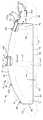
本発明を例示するものとして、装置10は車輛12の乗員を保護するのを補助する。図1及び図2に示すように、装置10は、膨張可能なカーテン14の形態の膨張可能な車輛乗員保護装置を含む。この装置は、車輛12の側方構造16及び車輛のルーフ18と隣接して取り付けられる。車輛12の側方構造16は、Aピラー30、Bピラー32、Cピラー34、及び前後の側方窓40及び42を含む。車輛12は、前側方窓40と隣接して位置決めされた車輛前座席44及び後側方窓42と隣接して位置決めされた車輛後座席46を更に含む。 As an illustration of the present invention, the
膨張器24が膨張可能なカーテン14に流体連通状態で連結されている。例示の実施例では、膨張可能なカーテン14は、膨張器24にクランプ等の手段28によって固定されたネック部分22を含む。別の態様では、ネック部分22は、マニホールド(図示せず)を介して膨張器24に連結されていてもよい。別の変形例では、装置10は、膨張流体を膨張可能なカーテン14に分配するために膨張可能なカーテン14に一部が配置された充填チューブ等の手段(図示せず)を含んでいてもよい。膨張器24には、膨張可能なカーテン14を膨張させるための所定量の加圧膨張流体(図示せず)がガスの形態で収容されている。膨張器24は、別の態様では、加圧膨張流体及びこの膨張流体を加熱するための点火可能な材料を含んでいてもよいし、ガス発生材料の燃焼を使用して膨張流体を発生する火工膨張器を含んでいてもよい。別の変形例として、膨張器24は、膨張可能なカーテン14を膨張させるための媒体を供給するための任意の適当な種類又は構造を備えていてもよい。 An
装置10は、膨張可能なカーテン14を収納された萎ませた状態に保持するのを補助する布シース又はプラスチックハウジング等のカバー26(図1参照)を含んでもよい。萎ませた状態の膨張可能なカーテン14及びカバー26は細長い形体を有し、車輛のルーフ18に沿って、及び車輛12の側方構造16に沿って、側方窓40及び42の上方を延びている。膨張可能なカーテン14及びカバー26は、以下に更に詳細に説明する支持手段120によって車輛12に連結できる。 The
膨張可能なカーテン(図3参照)は、互いに重ねられて配置された材料でできたパネル50及び52を含む。これらのパネル50及び52の重なった部分を膨張可能なカーテン14の周囲54の少なくとも一部に沿って相互連結し、カーテンの周囲連結部56を形成する。この周囲連結部56は、膨張可能なカーテン14の膨張可能な容積を画成するのを補助する。膨張可能なカーテン14は、更に、重なったパネル50及び52を周囲54内で相互連結し、カーテンの膨張不能なチャンバを画成するのを補助する膨張不能な部分を形成する内部連結部(図示せず)を含んでもよい。 The inflatable curtain (see FIG. 3) includes
膨張可能なカーテン14は、重なったパネル50及び52を合わせて単一の材料ピースにし、これらのパネルを縫い合わせること、又は超音波溶接、熱結合、又は接着剤でこれらのパネルを相互連結すること等の様々な方法で形成できる。1ピース織製構造では、重なったパネル50及び52をナイロン糸等の材料から同時に織製し、ウレタン等のガス不透過性材料でコーティングし、又はガス不透過性フィルムを積層する。かくして、膨張可能なカーテン14は実質的に気密構造を備えている。膨張可能なカーテン14を形成するため、ポリエステル糸等の別の材料及びシリコーン等の別のコーティングを使用してもよいということは当業者には理解されよう。 The
膨張可能なカーテン14の周囲54(図2参照)は、少なくとも部分的に、カーテンの上縁部70、反対側の下縁部、及びこれらの上下の縁部に沿って水平方向に間隔が隔てられた、膨張可能なカーテンの前後部分74及び76によって画成される。膨張可能なカーテン14の前後部分74及び76は、上下の縁部70及び72に沿って水平方向に間隔が隔てられており且つこれらの上下の縁部間を延びる前後の縁部80及び82を夫々含む。 The perimeter 54 (see FIG. 2) of the
図3、図4、及び図5に示すように、車輛の側方構造16と車輛ルーフ18との間の交差部に車輛ルーフレール100が配置されている。側方構造16、ルーフ18、及びルーフレール100は、型押し又は他の方法で所定形状にされ、溶接等によって連結されて所望構造を形成するシート金属のピースから形成される。図4及び図5に最もよく示すように、シート金属102及び104の夫々の外ピースを使用し、側方構造16、ルーフ18、及びルーフレール100を形成する。シート金属106でできた第3ピースは、車輛12のBピラー32を形成するのを補助する。側方構造16、ルーフ18、ルーフレール100、及びBピラー32は、別の形体及び/又は構造を備えていてもよいということは当業者には理解されよう。 As shown in FIGS. 3, 4, and 5, a
例示の実施例では、膨張可能なカーテン14、カバー26、及び支持手段120を組み立て、車輛12にユニットとして設置できるモジュール150にする。このモジュール150は、ボルトやねじ等のファスニング手段152によって車輛12に連結される。モジュール150は、更に、図4及び図5に示すように、ランプアッセンブリ160、及びルーフレール100と隣接して位置決めされたブラケット200、及びBピラー32を含む。ブラケット200は、Bピラー32と隣接して支持手段120を含む。 In the illustrated embodiment, the
ランプアッセンブリ160を図6に示す。ランプアッセンブリ160は、コネクタピース162及び展開ランプ180を含む。コネクタピース162は、曲げ、捩じり、又は他の形状の変更に対して抵抗をほとんど示さない全体に可撓性で非弾性の柔軟な材料で形成されている。展開ランプ180は、特にコネクタピース162の形成に使用された材料と比較して剛性であり且つ全体に弾性の材料で形成されている。展開ランプ180及びコネクタピース162は、単一のピースとして形成されていてもよいし、互いに連結された別体のピースとして形成されていてもよい。更に、展開ランプ180及びコネクタピース162は、種類が異なる材料で形成されていてもよいし同じ種類の材料で形成されていてもよい。 A
一例として、コネクタピース162は布材料で形成されていてもよく、展開ランプ180はプラスチック材料で形成されていてもよい。更に詳細には、コネクタピース162は織製ナイロン布材料で形成されていてもよく、展開ランプ180は型成形した熱可塑性エラストマー(TPE)材料で形成されていてもよい。展開ランプ180の形成に使用された材料は或る程度の可撓性を示す。しかしながら、いずれにせよ、展開ランプ180はコネクタピース162よりもかなり剛性である。 As an example, the
一例として、コネクタピース162及び展開ランプ180は、型成形したTPE材料等の同じ種類のプラスチック材料で形成されていてもよい。この例では、コネクタピース162及び展開ランプ180は、単一の材料ピースとして形成でき、又は互いに連結された別体のピースとして形成できる。展開ランプ180及びコネクタピース162の夫々の形体は、所望の特性を提供するように選択される。展開ランプ180は、ランプに所望程度の剛性を提供するため、比較的厚い形体又はリブを備えた形体等の形体を備えていてもよい。コネクタピース162は、コネクタピースに所望程度の可撓性を提供するため、比較的薄い形体等の形体を備えていてもよい。 As an example,
コネクタピース162は、車輛12及び/又はモジュール150の特定の構造に適合するように設計された様々な形状及び形体を備えていてもよい。図6に示す実施例では、コネクタピース162は全体に細長い矩形形体を有し、切り欠き部分164がコネクタピースの上縁部166に沿って中央に配置されている。切り欠き部分164は、ファスナを受け入れるための穴170を含むタブ部分168を画成するのを補助する。コネクタピース162は、更に、ブラケット200やカバー26等のモジュール150の部分を通過すことができるスリット172を備えていてもよい。 The
展開ランプ180は、車輛12及び/又はモジュール150の特定の構造に適合するように設計された様々な形状及び形体を備えていてもよい。図6に示す実施例では、展開ランプ180は全体に細長い矩形形体を有し、展開ランプの下縁部184に沿って間隔が隔てられた切り欠き隅部分182が設けられている。 The
コネクタピース162及び展開ランプ180は、コネクタピースの下縁部174が展開ランプ180の上縁部186と重なるように位置決めされる。これらの重なった部分174及び186を相互連結し、コネクタピース162を展開ランプ180に固定する。図6に示す実施例では、重なった部分174及び186は、縫い目188(例えばナイロン糸)によって相互連結される。重なった部分174及び186を相互連結するため、接着剤、超音波溶接、機械式ファスナ、又はこれらの組み合わせ等の別の手段を使用してもよい。 The
ブラケット200(図4及び図5参照)は、車輛12及び/又はモジュール150の特定の構造に適合するように設計された様々な形状及び形体を備えていてもよい。ブラケット200は、車輛12に設置したときに図4及び図5に示すようにルーフレール100と隣接して位置決めされる主部分202を含む。タブ部分204が主部分の上縁部206から主部分202まで横方向に延びる。ブラケット200は、更に、タブ部分204と少なくとも部分的に重なった強化部分210を含んでもよい。 The bracket 200 (see FIGS. 4 and 5) may have a variety of shapes and configurations designed to fit the particular structure of the
ブラケット200は、更に、主部分の下縁部222から主部分202まで横方向に延びるランプ支持部分220を含む。フランジ部分224が、主部分202の反対側のランプ支持部分の縁部からランプ支持部分220まで横方向に延びていてもよい。 The
ブラケット200は、金属等の高強度材料で形成されており、これは、型押し、ハイドロフォーミング、曲げ、及び機械加工等の様々な金属加工作業によって形成できる。ブラケット200を形成するためにプラスチックや複合材料等の別の材料及び別の構造を使用してもよい。例えば、ブラケット200の強化部分210及びブラケットの残りの部分を単一の材料ピースとして形成してもよいし、別体の材料ピースとして形成してもよい。 The
図4及び図5に示す、モジュール150を組み立てた状態では、膨張可能なカーテン14の上縁部70及びコネクタピース162のタブ部分168がタブ部分204と強化部分210との間に位置決めされる。ファスナ152が、強化部分210、膨張可能なカーテン14、コネクタピース162、及びタブ部分204を通って延び、ルーフレール100にねじ込まれ、モジュール150を車輛12に固定する。ファスナ152は、更に、カバーを車輛12に連結するため、カバー26(図4及び図5には示さず)を通って延びていてもよい。車輛12に設置されたとき、モジュール150は、側方構造16とルーフ18との交差部の近くでルーフレール100と隣接して位置決めされる。ブラケット200は、フック又はクリップ等の突出部240を含んでいてもよく、これは、先ず最初に、ファスナ152を設置するときにモジュール150を車輛12に支持するのを補助するのに使用される。 In the assembled state of the
モジュール150が車輛12に設置されたとき、ブラケット200の主部分202はルーフレール100に沿って、図4及び図5で見て車輛ルーフ18から全体に下方及び外方に延びる。ランプ支持部分220は、主部分202に対して横方向に、図4及び図5で見て車輛側方構造16から全体に遠ざかるように、車輛側方構造の斜め方向下方及び内方に延びる。主部分202及びランプ支持部分220は、膨張可能なカーテン14、カバー26、及びランプアッセンブリ160をきちんと収納された状態(図4参照)で受け入れるためのチャンネル242を形成する。膨張可能なカーテン14は、きちんと収納された状態にあるとき、丸められていたり、折り畳まれていたり、又はこれらの組み合わせがなされている。 When the
きちんと収納された状態では、ランプアッセンブリ160の展開ランプ180は、ランプ支持部分220から強化部分210のフランジ部分244に向かって延びるように位置決めされる。フランジ部分244は、膨張可能なカーテン14をきちんと収納された状態に保持するのを助ける。モジュール150は、展開ランプ180を図4に示すきちんと収納された位置に保持するため、切れ目を備えたストラップや繋ぎ紐等の手段(図示せず)を備えていてもよい。展開ランプ180は、きちんと収納された位置にある場合、膨張可能なカーテン14をチャンネル242内にきちんと収納された位置に維持し支持するのを補助する。 In the properly stowed state, the
モジュール150は、更に、図7及び図8に示すように、ルーフレール100及びCピラー34と隣接して位置決めされたランプアッセンブリ250を含む。Cピラー34と隣接して、支持手段120は支持クリップ280を含む。
ランプアッセンブリ250を図9に示す。ランプアッセンブリ250はコネクタピース252及び展開ランプ270を含む。コネクタピース252は、曲げ、捩じり、又は他の形状の変更に対して抵抗をほとんど示さない全体に可撓性で非弾性の柔軟な材料で形成されている。展開ランプ270は、特にコネクタピース252の形成に使用された材料と比較して剛性であり且つ全体に弾性の材料で形成されている。例えば、コネクタピース252は布材料で形成されていてもよく、展開ランプ270はプラスチック材料で形成されていてもよい。更に詳細には、コネクタピース252は織製ナイロン布材料で形成されていてもよく、展開ランプ270は型成形した熱可塑性エラストマー(TPE)材料で形成されていてもよい。展開ランプ270の形成に使用された材料は或る程度の可撓性を示す。しかしながら、いずれにせよ、展開ランプ270はコネクタピース252よりもかなり剛性である。 A
コネクタピース252は、車輛12及び/又はモジュール150の特定の構造に適合するように設計された様々な形状及び形体を備えていてもよい。図9に示す実施例では、コネクタピース252は全体に細長い矩形形体を有し、切り欠き部分254がコネクタピースの上縁部256に沿って中央に配置されている。この切り欠き部分254は、ファスナを受け入れるための穴260を含むタブ部分258を画成する。タブ部分258は、更に、以下に説明するように、保持部材を受け入れるための穴262を備えていてもよい。 The
展開ランプ270は、車輛12及び/又はモジュール150の特定の構造に適合するように設計された様々な形状及び形体を備えていてもよい。図9に示す実施例では、展開ランプ270は全体に細長い矩形形体を有し、展開ランプの下縁部274に沿って間隔が隔てられた切り欠き隅部分272が設けられている。 The
コネクタピース252及び展開ランプ270は、コネクタピースの下縁部264が展開ランプ270の上縁部276と重なるように位置決めされる。これらの重なった部分264及び276を相互連結し、コネクタピース252を展開ランプ270に固定する。図9に示す実施例では、重なった部分264及び276は、縫い目278(例えばナイロン糸)によって相互連結される。重なった部分264及び276を相互連結するため、接着剤、超音波溶接、機械式ファスナ、又はこれらの組み合わせ等の別の手段を使用してもよい。
図7及び図8に示す実施例では、支持クリップ280は全体にU形状断面を有し、重なった第1及び第2のクリッププレート282及び284を夫々含む。これは図7のAに最もよく示してある。第1及び第2のクリッププレート282及び284は、車輛12及び/又はモジュール150の特定の構造に適合するように設計された様々な形状及び形体を備えていてもよい。第1及び第2のクリッププレート282及び284は、互いに整合したファスナ受け入れ穴285を夫々有する。 In the embodiment shown in FIGS. 7 and 8, the
支持クリップ280は、金属等の高強度材料でできたピースで形成されている。支持クリップ280を形成するためにプラスチックや複合材料等の別の材料及び別の構造を使用してもよい。例えば、支持クリップ280の第1及び第2のクリッププレート282及び284を、図7及び図8に示す単一の材料ピースでなく、別体の材料ピースとして形成してもよい。 The
図7及び図8に示す、モジュール150を組み立てた状態では、膨張可能なカーテン14の上縁部70及びコネクタピース252のタブ部分258は、支持クリップ280の第1及び第2のクリッププレート282及び284間に位置決めされる。カバー26(図7、図8、及び図9には図示されていない)は、第1及び第2のクリッププレート282及び284間に位置決めされた部分を備えていてもよい。第1及び第2のクリッププレート282及び284は、互いに向かって延び且つ連結部分252の穴262及び膨張可能なカーテン14の上縁部70の近くの穴288を通って互いに係合できる保持部材286を夫々備えていてもよい。 In the assembled state of the
ファスナ152は、第1クリッププレート282、膨張可能なカーテン14、タブ部分258、及び第2クリッププレート284を通って延び、ルーフレール100にねじ込まれ、モジュール150を車輛12に固定する。車輛12に設置されたとき、モジュール150は、側方構造16とルーフ18との交差部近くでルーフレール100と隣接して位置決めされる。 The
図7及び図8に示す実施例では、フック等の部材290がランプアッセンブリ250のコネクタピース252に、縫合、超音波溶接、又は接着剤等の手段(図示せず)によって固定されている。部材290は、コネクタピース252から突出しており、これは、先ず最初に、ファスナ152を設置するときにモジュール150を車輛12に支持するのを補助するのに使用される。 7 and 8, a
モジュール150を車輛12に設置し、膨張可能なカーテン14がきちんと収納された状態にある場合、ランプアッセンブリ250の展開ランプ270が膨張可能なカーテン14をきちんと収納された位置に維持し且つ支持するのを補助する。モジュール150は、展開ランプ270を図7に示すきちんと収納された位置に保持するため、切れ目を備えたストラップや繋ぎ紐等の手段(図示せず)を備えていてもよい。 When the
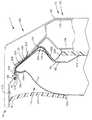
モジュール150は、図1、図4、及び図7の設置状態にある場合、ルーフレール100に沿って、及び側方構造16とルーフ18との交差部に沿って延びる。車輛12は、車輛のルーフ18の内面302に沿って延びるヘッドライナー300を含む。ヘッドライナー300は、モジュール150と隣接してルーフ18に対して鋭角をなして延びる部分304を有する。ヘッドライナー300の部分304は、モジュール150と重なり、モジュールを車輛12内に隠す。ヘッドライナー300の末端306は、Bピラー32と重なるトリムピース310(図4参照)及びCピラー34と重なるトリムピース312(図7参照)と衝合係合している。 The
車輛構造の形体、及びかくして車輛構造(即ち側方構造16、ルーフ18、及びルーフレール100)と、ヘッドライナー300、トリムピース310、及びモジュール150との間の空間的及び相互連結関係は、車輛12の特定の設計に応じて変化するということは当業者には理解されよう。従って、図4、図5、図7、及び図8に示す車輛構造、及びこの車輛構造と、ヘッドライナー300、トリムピース310及び312、及びモジュール150との間の空間的及び相互連結関係は、例示の目的のためであって、本発明の精神から逸脱することなく変化させることができるということは理解されるべきである。 The spatial and interconnection relationship between the vehicle structure configuration, and thus the vehicle structure (i.e., the
車輛12は、膨張可能なカーテン14を膨張させるのが望ましい、車輛12への側方衝突及び/又は車輛の転覆等の状況が生じたことを検出するためのセンサ機構350を含む(図1及び図2に概略に示す)。このような状況が生じたことが検出されたとき、センサ機構350は、リード線352を通して膨張器24に電気信号を提供する。この電気信号により、膨張器24を周知の方法で賦勢する。膨張器24は、賦勢されたとき、加圧流体を膨張可能なカーテン14内に放出する。 The
膨張可能なカーテン14は、膨張器24からの膨張流体の圧力の作用で膨張する。これにより、カバー26を開放し、カーテンをルーフ18から遠ざかるように下方に添付図面に示すように、及び車輛12の前方への移動方向に関して下方に図2、図5、及び図8に示す状態にまで膨張させる。 The
膨張可能なカーテン14は、膨張させたとき、車輛12の側方構造16に沿って延び、側方構造と車輛の乗員との間に位置決めされる。膨張可能なカーテン14は、車輛12のAピラー30とCピラー34との間を延びる車輛の側方構造の位置を覆い、車輛のAピラー、Cピラー、Bピラー32の部分と重なる。膨張可能なカーテン14は、膨張させたとき、車輛側方構造16と車輛の前後の座席44及び46との間に位置決めされる。 When inflated, the
車輛12における膨張可能なカーテン14の長さ及び範囲は変化させることができるといことは当業者には理解されよう。例えば、膨張可能なカーテン14の長さ及び範囲は、車輛12の構造、車輛での膨張可能なカーテン14の位置、及び膨張可能なカーテンの所望の長さ及び範囲等の様々な要因に応じて変化する。 Those skilled in the art will appreciate that the length and range of the
膨張可能なカーテン14は、膨張させたとき、車輛の転覆時又は側方衝突時に車輛乗員を保護するのを補助する。膨張可能なカーテン14は、Aピラー30からCピラー34まで延びる側方構造16の領域を、ルーフ18から側方窓40及び42と隣接した、又はその下方の位置まで覆う。膨張可能なカーテン14は、膨張させたとき、衝撃のエネルギをカーテンで吸収するのを補助し、衝撃エネルギをカーテンの大きな面積に亘って分配するのを補助する。 The
図4及び図5を参照すると、展開ランプ180は、膨張可能なカーテン14をトリムピース310の内側で、トリムピースと車輛12の乗員との間で膨張するように逸らし即ち他の態様で差し向けるのを補助する。膨張可能なカーテン14の膨張中、可撓性コネクタピース162により展開ランプ180を図4の位置から図5の位置に向かって移動させることができる。コネクタピース162の布構造は、展開ランプ180が実質的に制限なく移動できるように、十分に非弾性であり且つ可撓性である。これにより、展開ランプ180は迅速に且つほとんど抵抗を受けることなく展開位置に達することができ、そのため膨張可能なカーテン14は展開ランプからほとんど又は全く抵抗を受けることなく展開できる。展開ランプ180は、展開したとき、トリムピース310、側方構造16、及びフランジ部分224の領域と重なる。 With reference to FIGS. 4 and 5, the
展開ランプ180は、膨張可能なカーテン14とトリムピース310との間に障壁を形成し、及びかくしてカーテンがトリムピースに捕捉されたりトリムピースと側方構造16との間で膨張したりしないようにするのを補助する。展開ランプ180は、膨張可能なカーテン14をトリムピース310の周囲で内方(即ち図3、図4、及び図5で見て左方)に展開するように差し向ける。図5に示すように、展開ランプ180は膨張可能なカーテン14の力の作用で曲がったり撓んだりできる。しかしながら、このような曲げや撓みが起こった場合でも、展開ランプ180は、膨張可能なカーテン14をトリムピース310の内方に差し向ける上で十分に剛性であり且つ弾性のままである。ブラケット200のランプ支持部分220は、膨張可能なカーテン14の展開中に展開ランプ180を支持するのを補助する。 The
図7及び図8を参照すると、展開ランプ270は、膨張可能なカーテン14をトリムピース312の内側で、トリムピースと車輛12の乗員との間で膨張するように逸らし即ち他の態様で差し向けるのを補助する。膨張可能なカーテン14の膨張中、可撓性連結部分252により展開ランプ270を図7の位置から図8の位置に向かって移動させることができる。連結部分252の布構造は、展開ランプ270が実質的に制限なく移動できるように、十分に非弾性であり且つ可撓性である。これにより、展開ランプ270は迅速に且つほとんど抵抗を受けることなく展開位置に達することができ、そのため膨張可能なカーテン14は展開ランプからほとんど又は全く抵抗を受けることなく展開できる。展開ランプ270は、展開したとき、トリムピース312の内方に延び、トリムピース312が側方構造16と隣接して終端する領域と重なる。 With reference to FIGS. 7 and 8, the
展開ランプ270は、膨張可能なカーテン14とトリムピース312との間に障壁を形成し、及びかくしてカーテンがトリムピースに捕捉されたりトリムピースと側方構造16との間で膨張したりしないようにするのを補助する。展開ランプ270は、膨張可能なカーテン14をトリムピース312の周囲で内方(即ち図7及び図8で見て左方)に展開するように差し向ける。図8に示すように、展開ランプ270は膨張可能なカーテン14の力の作用で曲がったり撓んだりできる。しかしながら、このような曲げや撓みが起こった場合でも、展開ランプ270は、膨張可能なカーテン14をトリムピース312の内方に差し向けように十分に剛性であり且つ弾性のままである。 The
当業者は、本発明の以上の説明から、改良、変更、及び変形を思いつくであろう。例えば、コネクタピースの形成にプラスチックフィルム等の別の可撓性材料を使用してもよい。展開ランプの形成に金属や複合材料等の変形例の剛性材料を使用してもよい。当該技術分野の技術範囲内のこのような改良、変更、及び変形は、特許請求の範囲に含まれる。 From the above description of the invention, those skilled in the art will perceive improvements, changes, and modifications. For example, another flexible material such as a plastic film may be used to form the connector piece. Variations of rigid materials such as metals and composite materials may be used to form the unfolding lamp. Such improvements, changes and modifications within the skill of the art are intended to be covered by the appended claims.
10 装置
12 車輛
14 膨張可能なカーテン
16 側方構造
18 車輛ルーフ
22 ネック部分
24 膨張器
26 カバー
28 クランプ
30 Aピラー
32 Bピラー
34 Cピラー
40、42 側方窓
44 車輛前座席
46 車輛後座席
120 支持手段
50、52 パネル
54 周囲
56 周囲連結部DESCRIPTION OF
Claims (17)
Translated fromJapanese前記車輛ルーフから遠ざかる方向に前記車輛の前記側方構造と隣接した位置まで膨張できる膨張可能なカーテンと、
前記膨張可能なカーテンを前記トリムピースの内側に展開するように差し向けるため、収納位置から展開位置まで移動でき、前記膨張可能なカーテンを前記トリムピースの内側に展開するように差し向けるのに十分に弾性であり且つ剛性の構造を持つ、展開ランプと、
前記展開ランプに固定された第1部分及び前記車輛に連結できる第2部分を持ち、前記展開ランプが前記展開位置まで実質的に制限なしに移動できるように十分に非弾性であり且つ可撓性の構造を持つ、前記展開ランプを前記車輛に連結するためのコネクタピースと
を含む、装置。In a device for assisting the protection of a vehicle occupant comprising a roof, a side structure and a trim piece overlapping the side structure,
An inflatable curtain capable of expanding to a position adjacent to the side structure of the vehicle in a direction away from the vehicle roof;
Because the inflatable curtain is directed to deploy inside the trim piece, it can be moved from a stowed position to a deployed position and is sufficient to direct the inflatable curtain to deploy inside the trim piece A deployment lamp that is elastic and has a rigid structure;
A first portion fixed to the deployment ramp and a second portion connectable to the vehicle; sufficiently inelastic and flexible so that the deployment ramp can move to the deployment position substantially without restriction And a connector piece for connecting the deployment lamp to the vehicle.
前記膨張可能なカーテンを前記トリムピースの内側に展開するように差し向けるためのプラスチック製展開ランプと、
前記展開ランプを前記車輛に連結するための、前記展開ランプに連結された第1部分及び前記車輛に連結できる第2部分を持つ布製コネクタピースと
を含む、装置。In an apparatus for directing an inflatable curtain to deploy inside a trim piece that overlaps a side structure of a vehicle,
A plastic deployment lamp for directing the inflatable curtain to deploy inside the trim piece;
An apparatus comprising: a fabric connector piece having a first portion coupled to the deployment lamp and a second portion connectable to the vehicle for coupling the deployment lamp to the vehicle.
Applications Claiming Priority (1)
| Application Number | Priority Date | Filing Date | Title |
|---|---|---|---|
| US10/819,752US7182366B2 (en) | 2004-08-27 | 2004-08-27 | Inflatable curtain deployment ramp |
Publications (2)
| Publication Number | Publication Date |
|---|---|
| JP2006062642Atrue JP2006062642A (en) | 2006-03-09 |
| JP4102396B2 JP4102396B2 (en) | 2008-06-18 |
Family
ID=35942016
Family Applications (1)
| Application Number | Title | Priority Date | Filing Date |
|---|---|---|---|
| JP2005241983AExpired - LifetimeJP4102396B2 (en) | 2004-08-27 | 2005-08-24 | Deployment lamp for inflatable curtain |
Country Status (2)
| Country | Link |
|---|---|
| US (1) | US7182366B2 (en) |
| JP (1) | JP4102396B2 (en) |
Cited By (2)
| Publication number | Priority date | Publication date | Assignee | Title |
|---|---|---|---|---|
| JP2010285069A (en)* | 2009-06-11 | 2010-12-24 | Honda Motor Co Ltd | Airbag device for vehicle |
| JP2014113941A (en)* | 2012-12-11 | 2014-06-26 | Toyota Auto Body Co Ltd | Air bag guide case |
Families Citing this family (30)
| Publication number | Priority date | Publication date | Assignee | Title |
|---|---|---|---|---|
| JP4453543B2 (en)* | 2004-12-21 | 2010-04-21 | 豊田合成株式会社 | Head protection airbag device |
| KR100598685B1 (en)* | 2004-12-23 | 2006-07-07 | 현대자동차주식회사 | Curtain air bag mounting structure |
| US20060197317A1 (en)* | 2005-03-07 | 2006-09-07 | Takata Corporation | Airbag attachment structure |
| KR100757153B1 (en)* | 2005-12-12 | 2007-09-07 | 현대자동차주식회사 | Filler lamp construction to prevent curtain air bag interference |
| US7520527B2 (en)* | 2006-03-29 | 2009-04-21 | Mazda Motor Corporation | Vehicle rear structure provided with curtain air bag device |
| JP4987540B2 (en)* | 2006-04-04 | 2012-07-25 | オートリブ ディベロップメント エイビイ | Side airbag guide plate |
| EP1857333A3 (en)* | 2006-05-19 | 2008-06-25 | Illinois Tool Works Inc. | Fastener for air-bag curtain |
| US7597342B2 (en)* | 2006-05-26 | 2009-10-06 | Autoliv Asp, Inc. | Energy absorbing feature for inflatable curtain airbag |
| JP4864660B2 (en)* | 2006-06-23 | 2012-02-01 | 本田技研工業株式会社 | Curtain airbag device and airbag module |
| JP4211825B2 (en)* | 2006-09-06 | 2009-01-21 | トヨタ自動車株式会社 | Pillar garnish mounting structure in a vehicle equipped with a head protection airbag device |
| JP5133042B2 (en)* | 2007-12-19 | 2013-01-30 | 芦森工業株式会社 | Deployment restriction member for curtain airbag and arrangement structure of curtain airbag |
| US9004525B2 (en)* | 2009-06-26 | 2015-04-14 | Trw Vehicle Safety Systems Inc. | Co-extruded inflatable curtain deployment ramp |
| US7980585B2 (en)* | 2009-06-30 | 2011-07-19 | Autoliv Asp, Inc. | Airbag mounting assemblies with double-locking wrappers |
| US8006998B2 (en)* | 2009-07-22 | 2011-08-30 | Autoliv Asp, Inc. | Inflatable airbag assemblies with modular components and related methods of manufacture |
| US8056924B2 (en) | 2009-08-20 | 2011-11-15 | Autoliv Asp, Inc. | Inflatable airbag assemblies with alignment apertures |
| US8240701B2 (en)* | 2009-09-08 | 2012-08-14 | Autoliv Asp, Inc. | Mounting assemblies with wrappers for inflatable curtain airbags |
| US8091918B2 (en)* | 2010-01-19 | 2012-01-10 | Autoliv Asp, Inc. | Double-sewn airbag mounting assemblies |
| US8702124B2 (en)* | 2011-09-21 | 2014-04-22 | Chrysler Group Llc | Side airbag deployment arrangement |
| US8500162B2 (en)* | 2011-12-22 | 2013-08-06 | Autoliv Asp, Inc. | Inflatable curtain airbag with an integrated pillar guide |
| JP5804528B2 (en)* | 2013-03-12 | 2015-11-04 | 株式会社豊田自動織機 | Curtain airbag device |
| WO2015175587A1 (en)* | 2014-05-13 | 2015-11-19 | Key Safety Systems Inc. | Improved side curtain airbag |
| US9045108B1 (en)* | 2014-06-04 | 2015-06-02 | Toyota Motor Engineering & Manufacturing North America, Inc. | Airbag reinforcement material at an airbag gas inlet |
| US9637081B2 (en)* | 2014-07-14 | 2017-05-02 | Ford Global Technologies, Llc | Curtain airbag with protective sheet |
| CN108367726B (en)* | 2015-10-07 | 2020-11-13 | 关键安全体系股份有限公司 | Side curtain airbag module |
| GB2558999B (en) | 2016-01-19 | 2019-06-12 | Ford Global Tech Llc | A component of a motor vehicle |
| US11235730B2 (en)* | 2018-11-26 | 2022-02-01 | Vintech Industries, Inc. | Extruded airbag ramp |
| US11312328B2 (en) | 2019-06-26 | 2022-04-26 | Autoliv Asp, Inc. | Vehicle trim opening device for airbag deployment |
| KR20220099706A (en)* | 2021-01-07 | 2022-07-14 | 현대모비스 주식회사 | Airbag for vehicle |
| US11608021B2 (en)* | 2021-07-21 | 2023-03-21 | ZF Passive Safety Systems US Inc. | Curtain airbag module with deployment ramp and bag wrap retention features |
| US11628796B2 (en)* | 2021-08-23 | 2023-04-18 | ZF Passive Safety Systems US Inc. | Curtain airbag deployment ramp with mounting tabs |
Family Cites Families (20)
| Publication number | Priority date | Publication date | Assignee | Title |
|---|---|---|---|---|
| JP3218966B2 (en) | 1996-03-13 | 2001-10-15 | 豊田合成株式会社 | Garnish member with built-in airbag device |
| JP3129408B2 (en) | 1996-11-07 | 2001-01-29 | トヨタ自動車株式会社 | Installation structure of vehicle occupant protection system |
| JP3125729B2 (en) | 1997-09-26 | 2001-01-22 | トヨタ自動車株式会社 | Arrangement structure of head protection airbag bag |
| US6254123B1 (en) | 1998-08-03 | 2001-07-03 | Toyota Jidosha Kabushiki Kaisha | Mounting structure for use with a head-protecting airbag body |
| US6257616B1 (en) | 1998-12-23 | 2001-07-10 | Prince Technology Corporation | Headliner assembly |
| US6142509A (en) | 1999-02-05 | 2000-11-07 | Trw Vehicle Safety Systems Inc. | Fastener structure for a vehicle occupant protection apparatus including an inflatable curtain |
| US6022044A (en) | 1999-03-29 | 2000-02-08 | Trw Vehicle Safety Systems Inc. | Support device for a vehicle occupant safety apparatus |
| US6149185A (en) | 1999-06-07 | 2000-11-21 | Trw Vehicle Safety Systems Inc. | Support device for a vehicle occupant safety apparatus |
| JP3460636B2 (en) | 1999-08-23 | 2003-10-27 | トヨタ自動車株式会社 | Head protection airbag device |
| US6217061B1 (en) | 2000-02-18 | 2001-04-17 | Daimlerchrysler Corporation | Airbag system within impact countermeasures |
| DE20015135U1 (en) | 2000-09-01 | 2001-01-11 | TRW Occupant Restraint Systems GmbH & Co. KG, 73553 Alfdorf | Airbag restraint system |
| US6439598B1 (en) | 2000-10-24 | 2002-08-27 | Trw Vehicle Safety Systems Inc. | Housing for inflatable vehicle occupant protection device |
| US6364349B1 (en)* | 2001-04-20 | 2002-04-02 | Trw Vehicle Safety Systems Inc. | Inflatable curtain housing with deployment flap |
| JP3778498B2 (en) | 2002-02-04 | 2006-05-24 | 本田技研工業株式会社 | Vehicle occupant protection device |
| JP3928451B2 (en) | 2002-03-20 | 2007-06-13 | 豊田合成株式会社 | Head protection airbag device |
| US6793241B2 (en) | 2002-05-01 | 2004-09-21 | Trw Vehicle Safety Systems Inc. | Modular headliner and inflatable curtain assembly |
| US6886858B2 (en)* | 2002-07-26 | 2005-05-03 | Key Safety Systems, Inc. | Air bag assembly with tethers in a woven cushion and method of construction |
| US20040108693A1 (en)* | 2002-12-06 | 2004-06-10 | Foster Jason S. | Device for unrestricted side airbag or curtain deployment |
| US20050046154A1 (en)* | 2003-09-03 | 2005-03-03 | Rhea Scott L. | Inflatable curtain mounting bracket |
| US7175196B2 (en)* | 2004-02-09 | 2007-02-13 | Trw Vehicle Safety Systems Inc. | Support bracket for an inflatable curtain |
- 2004
- 2004-08-27USUS10/819,752patent/US7182366B2/ennot_activeExpired - Lifetime
- 2005
- 2005-08-24JPJP2005241983Apatent/JP4102396B2/ennot_activeExpired - Lifetime
Cited By (2)
| Publication number | Priority date | Publication date | Assignee | Title |
|---|---|---|---|---|
| JP2010285069A (en)* | 2009-06-11 | 2010-12-24 | Honda Motor Co Ltd | Airbag device for vehicle |
| JP2014113941A (en)* | 2012-12-11 | 2014-06-26 | Toyota Auto Body Co Ltd | Air bag guide case |
Also Published As
| Publication number | Publication date |
|---|---|
| JP4102396B2 (en) | 2008-06-18 |
| US20060043703A1 (en) | 2006-03-02 |
| US7182366B2 (en) | 2007-02-27 |
Similar Documents
| Publication | Publication Date | Title |
|---|---|---|
| JP4102396B2 (en) | Deployment lamp for inflatable curtain | |
| US7175196B2 (en) | Support bracket for an inflatable curtain | |
| JP3859343B2 (en) | Seamless lateral expansion restraint deployment system | |
| US8833852B2 (en) | Vehicle seat assembly | |
| JP4893043B2 (en) | Pedestrian airbag device | |
| US6412810B1 (en) | Inflatable side air bag curtain module | |
| US7290791B2 (en) | Vehicle seat assembly with air bag guide retainer | |
| JP5808983B2 (en) | Airbag device | |
| US20060113758A1 (en) | Vehicle seat assembly | |
| US20030107209A1 (en) | Pop-up vehicle occupant protection device | |
| US20070228709A1 (en) | Airbag with gas diffuser | |
| JP2002362280A (en) | Head protective air bag device | |
| US9004525B2 (en) | Co-extruded inflatable curtain deployment ramp | |
| US7377542B2 (en) | Vehicle seat side air bag system | |
| JP4345637B2 (en) | Airbag device | |
| US20060267315A1 (en) | Bracket assembly for an inflatable curtain | |
| WO2023003744A1 (en) | Curtain airbag module with deployment ramp and bag wrap retention features | |
| JP3757326B2 (en) | Head protection airbag device airbag | |
| US11628796B2 (en) | Curtain airbag deployment ramp with mounting tabs | |
| JP3520507B2 (en) | Head protection airbag | |
| US20060138748A1 (en) | Head protecting airbag | |
| JP3626701B2 (en) | Crew restraint system | |
| JP2003002150A (en) | Head protective air bag device | |
| JP2014054955A (en) | Air bag device | |
| JP3991752B2 (en) | Car |
Legal Events
| Date | Code | Title | Description |
|---|---|---|---|
| A131 | Notification of reasons for refusal | Free format text:JAPANESE INTERMEDIATE CODE: A131 Effective date:20070802 | |
| A601 | Written request for extension of time | Free format text:JAPANESE INTERMEDIATE CODE: A601 Effective date:20071101 | |
| A602 | Written permission of extension of time | Free format text:JAPANESE INTERMEDIATE CODE: A602 Effective date:20071106 | |
| A521 | Request for written amendment filed | Free format text:JAPANESE INTERMEDIATE CODE: A523 Effective date:20080131 | |
| TRDD | Decision of grant or rejection written | ||
| A01 | Written decision to grant a patent or to grant a registration (utility model) | Free format text:JAPANESE INTERMEDIATE CODE: A01 Effective date:20080222 | |
| A61 | First payment of annual fees (during grant procedure) | Free format text:JAPANESE INTERMEDIATE CODE: A61 Effective date:20080321 | |
| FPAY | Renewal fee payment (event date is renewal date of database) | Free format text:PAYMENT UNTIL: 20110328 Year of fee payment:3 | |
| R150 | Certificate of patent or registration of utility model | Ref document number:4102396 Country of ref document:JP Free format text:JAPANESE INTERMEDIATE CODE: R150 Free format text:JAPANESE INTERMEDIATE CODE: R150 | |
| R250 | Receipt of annual fees | Free format text:JAPANESE INTERMEDIATE CODE: R250 | |
| FPAY | Renewal fee payment (event date is renewal date of database) | Free format text:PAYMENT UNTIL: 20120328 Year of fee payment:4 | |
| FPAY | Renewal fee payment (event date is renewal date of database) | Free format text:PAYMENT UNTIL: 20130328 Year of fee payment:5 | |
| R250 | Receipt of annual fees | Free format text:JAPANESE INTERMEDIATE CODE: R250 | |
| FPAY | Renewal fee payment (event date is renewal date of database) | Free format text:PAYMENT UNTIL: 20130328 Year of fee payment:5 | |
| FPAY | Renewal fee payment (event date is renewal date of database) | Free format text:PAYMENT UNTIL: 20140328 Year of fee payment:6 | |
| R250 | Receipt of annual fees | Free format text:JAPANESE INTERMEDIATE CODE: R250 | |
| R250 | Receipt of annual fees | Free format text:JAPANESE INTERMEDIATE CODE: R250 | |
| R250 | Receipt of annual fees | Free format text:JAPANESE INTERMEDIATE CODE: R250 | |
| R250 | Receipt of annual fees | Free format text:JAPANESE INTERMEDIATE CODE: R250 | |
| R250 | Receipt of annual fees | Free format text:JAPANESE INTERMEDIATE CODE: R250 | |
| R250 | Receipt of annual fees | Free format text:JAPANESE INTERMEDIATE CODE: R250 | |
| R250 | Receipt of annual fees | Free format text:JAPANESE INTERMEDIATE CODE: R250 | |
| R250 | Receipt of annual fees | Free format text:JAPANESE INTERMEDIATE CODE: R250 | |
| R250 | Receipt of annual fees | Free format text:JAPANESE INTERMEDIATE CODE: R250 | |
| R250 | Receipt of annual fees | Free format text:JAPANESE INTERMEDIATE CODE: R250 | |
| R250 | Receipt of annual fees | Free format text:JAPANESE INTERMEDIATE CODE: R250 | |
| R250 | Receipt of annual fees | Free format text:JAPANESE INTERMEDIATE CODE: R250 | |
| R250 | Receipt of annual fees | Free format text:JAPANESE INTERMEDIATE CODE: R250 |