JP2006060914A - Motor cooling structure and manufacturing method thereof - Google Patents
Motor cooling structure and manufacturing method thereofDownload PDFInfo
- Publication number
- JP2006060914A JP2006060914AJP2004239832AJP2004239832AJP2006060914AJP 2006060914 AJP2006060914 AJP 2006060914AJP 2004239832 AJP2004239832 AJP 2004239832AJP 2004239832 AJP2004239832 AJP 2004239832AJP 2006060914 AJP2006060914 AJP 2006060914A
- Authority
- JP
- Japan
- Prior art keywords
- housing
- core
- motor
- edge
- cooling water
- Prior art date
- Legal status (The legal status is an assumption and is not a legal conclusion. Google has not performed a legal analysis and makes no representation as to the accuracy of the status listed.)
- Pending
Links
Images


Landscapes
- Motor Or Generator Frames (AREA)
- Motor Or Generator Cooling System (AREA)
- Manufacture Of Motors, Generators (AREA)
Abstract
Translated fromJapaneseDescription
Translated fromJapanese本発明は、内側にモータ部を収容するハウジングに形成される冷却液通路部を備えるモータの冷却構造、およびその製造方法に関する。 The present invention relates to a cooling structure for a motor including a coolant passage formed in a housing that accommodates the motor inside, and a method for manufacturing the same.
モータは、ロータとステータとからなるモータ部と、モータ部を内側に収容する筒状のハウジングとを備えている。モータ部は、駆動することによって過熱する。このため、モータ部の過熱を防ぐ冷却構造の一例として、ハウジングの側壁に冷却水通路部が形成されている。 The motor includes a motor unit including a rotor and a stator, and a cylindrical housing that houses the motor unit inside. The motor part is overheated by driving. For this reason, the cooling water passage part is formed in the side wall of a housing as an example of the cooling structure which prevents overheating of a motor part.
しかし、冷却水通路部は、加工上の制約があるので、1つの部材で形成することが難しい。このため、ハウジングを径方向に2分割し、内側のハウジングと外側のハウジングのそれぞれ対向面に溝を形成することによって冷却水通路部を形成することが提案されている(例えば、特許文献1参照。)。 However, it is difficult to form the cooling water passage portion with a single member due to processing restrictions. For this reason, it has been proposed to form the cooling water passage portion by dividing the housing into two in the radial direction and forming grooves on the opposing surfaces of the inner housing and the outer housing (see, for example, Patent Document 1). .)
内側ハウジングと外側ハウジングとの間には、冷却水が漏れることを防止するシール部材が設けられている。外側ハウジングの一端部は、内側ハウジングの挿入端部と略面一になっており、カバー部材によって固定されて相対位置がずれないようになっている。
しかし、特許文献1の冷却水通路では、シール部材が切れたりするなどシール部材に不具合が生じると、冷却水通路から漏れた冷却水は、内側ハウジングと外側ハウジングとの間を通り、かつ内側ハウジングとカバー部材との間を通って内側ハウジングの内側に浸入することが考えられる。 However, in the cooling water passage of Patent Document 1, when a failure occurs in the sealing member such as the sealing member being cut, the cooling water leaking from the cooling water passage passes between the inner housing and the outer housing, and the inner housing. It is conceivable to penetrate between the cover member and the inside of the inner housing.
内側ハウジングの内側にはモータ部が収容されているので、冷却液が内側ハウジングの内側に浸入することは好ましくない。 Since the motor part is accommodated inside the inner housing, it is not preferable that the coolant enters the inside of the inner housing.
したがって、本発明の目的は、冷却液がハウジングの内側に侵入することを防止できるモータの冷却構造を提供することにある。 Therefore, an object of the present invention is to provide a motor cooling structure capable of preventing the coolant from entering the inside of the housing.
本発明のモータの冷却構造は、ハウジングと、冷却液通路部とを備える。ハウジングは、内側にモータ部を収容する。冷却液通路部は、ハウジングの側壁に形成される。冷却液通路部は、冷却液通路と、蓋部材とを備える。冷却液通路は、外側に張り出す中子支持部を有するとともに冷却液通路部の空間に応じた中子を用いてハウジングを成型することによって、ハウジングの側壁の厚み内部にハウジングの周方向に沿って連続して形成される。蓋部材は、ハウジングの側壁の外面に開口した中子支持部の跡を塞ぐ。 The motor cooling structure of the present invention includes a housing and a coolant passage section. A housing accommodates a motor part inside. The coolant passage portion is formed on the side wall of the housing. The coolant passage section includes a coolant passage and a lid member. The cooling fluid passage has a core support portion that protrudes outward and is molded along the circumferential direction of the housing within the thickness of the side wall of the housing by molding the housing using a core corresponding to the space of the cooling fluid passage portion. Are formed continuously. The lid member closes the trace of the core support portion opened on the outer surface of the side wall of the housing.
ハウジングの充分な強度を確保するとともに、効果的にモータ部を冷却するために、中子は、第1の連通部と第2の連通部とを備える。第1の連通部は、ハウジングの成型時にハウジングの軸心線方向を横切る中子の両縁のうち、一方の第1の縁から他方の第2の縁に向かって第2の縁に達さない範囲で一部を切り欠くことによって形成され、中子の内側と中子の外側とを一部連通する。第2の連通部は、第2の縁から第1の縁に向かって第1の縁に達さない範囲で一部を切り欠くことによって形成され、中子の内側と中子の外側とを一部連通する。第1の連通部と第2の連通部とは、中子の周方向に交互に形成される。第1の連通部の先端は、第2の連通部の先端を越えて第2の縁側まで延びる。第2の連通部の先端は、第1の連通部の先端を越えて第1の縁側まで延びる。 In order to ensure sufficient strength of the housing and effectively cool the motor portion, the core includes a first communication portion and a second communication portion. The first communication portion reaches the second edge from one first edge toward the other second edge of both edges of the core that crosses the axial center line direction of the housing when the housing is molded. It is formed by cutting out a part of the core, and the inner side of the core and the outer side of the core are partially communicated. The second communication portion is formed by cutting out a part from the second edge toward the first edge in a range that does not reach the first edge, and connects the inner side of the core and the outer side of the core. Some communicate. The first communication portion and the second communication portion are alternately formed in the circumferential direction of the core. The tip of the first communication portion extends to the second edge side beyond the tip of the second communication portion. The tip of the second communication portion extends to the first edge side beyond the tip of the first communication portion.
このように形成される中子を用いることによって、冷却液通路内において第1の連通部と第2の連通部に対応する位置は、ハウジングの側壁の厚み部分となり、補強部として機能する。さらに、第1の連通部と第2の連通部とが交互に形成される。そして、第1の連通部の先端が第2の連通部の先端を越えて延び、第2の連通部の先端が第1の連通部の先端を越えて延びている。このため、冷却液通路は、ジグザグに形成されるので、冷却液は、よどみなく流れる。 By using the core formed in this way, the position corresponding to the first communication portion and the second communication portion in the coolant passage becomes the thickness portion of the side wall of the housing and functions as a reinforcing portion. Furthermore, the 1st communication part and the 2nd communication part are formed alternately. The tip of the first communication portion extends beyond the tip of the second communication portion, and the tip of the second communication portion extends beyond the tip of the first communication portion. For this reason, since the coolant passage is formed in a zigzag, the coolant flows without stagnation.
本発明のモータの冷却構造の製造方法では、モータは、筒状のハウジングと、冷却液通路部とを備える。モータは、内側にモータ部を収容する。冷却液通路部は、ハウジングの側壁に形成される。まず、ハウジングを成型する成型空間の内部に、冷却液通路部の空間に応じた中子を配置するとともに外側に張り出す中子支持部によって中子を支持する。その後、成型空間内でハウジングを鋳造し、鋳造によって成型されたハウジングから中子および中子支持部を除去する。その後、ハウジングの側壁の外面に開口した中子支持部の跡を蓋部材によって塞ぐ。 In the method for manufacturing a cooling structure for a motor of the present invention, the motor includes a cylindrical housing and a coolant passage portion. The motor houses the motor part inside. The coolant passage portion is formed on the side wall of the housing. First, a core corresponding to the space of the coolant passage portion is disposed inside a molding space for molding the housing, and the core is supported by a core support portion projecting outward. Thereafter, the housing is cast in the molding space, and the core and the core support portion are removed from the housing molded by casting. Then, the trace of the core support part opened on the outer surface of the side wall of the housing is closed with a lid member.
本発明のモータの冷却構造では、外側に張り出す中子支持部を有する中子を用いてハウジングを成型することによって、冷却液通路をハウジングの側壁の厚み内部に形成するとともに、中子支持部の跡をハウジングの側壁の外面に形成することができる。そして、該穴を、蓋部材によって塞いでいる。 In the motor cooling structure of the present invention, the housing is molded by using the core having the core support portion that protrudes outward, so that the coolant passage is formed within the thickness of the side wall of the housing, and the core support portion. Can be formed on the outer surface of the side wall of the housing. The hole is closed with a lid member.
それゆえ、複数の部材からなる冷却液通路部において、液漏れが懸念される部位、つまり本発明では中子支持部の跡、をハウジングの外面に配置することができる。このため、穴と蓋部材との間から、万一、冷却液が漏れても、漏れた冷却液は、ハウジングの外側に出るので、ハウジングの内側に侵入しない。 Therefore, in the coolant passage portion composed of a plurality of members, a portion where liquid leakage is a concern, that is, in the present invention, the trace of the core support portion can be disposed on the outer surface of the housing. For this reason, even if the coolant leaks from between the hole and the lid member, the leaked coolant goes out of the housing and does not enter the inside of the housing.
このように、本発明のモータの冷却構造は、ハウジングの内側に冷却液が浸入することを防止できる。 Thus, the motor cooling structure of the present invention can prevent the coolant from entering the inside of the housing.
本発明に係るモータの冷却構造の一実施形態を図1から図7を参照して説明する。
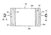
モータ10は、ハウジング20と、第1のカバー部材21と、第2のカバー部材22と、モータ部30となどを備えている。An embodiment of a motor cooling structure according to the present invention will be described with reference to FIGS.
The
ハウジング20は、例えば円筒状である。第1のカバー部材21は、ハウジング20の第1の開口部20aを覆っている。第2のカバー部材22は、ハウジング20の第2の開口部20bを覆っている。なお、本実施形態では、図中左側のハウジング20の開口部を第1の開口部20aとし、図中右側のハウジングの開口部を第2の開口部20bとしている。 The
第1のカバー部材21とハウジング20の端面との間には、シール部材40が設けられている。第2のカバー部材22とハウジング20の端面との間には、シール部材40が設けられている。 A
モータ部30は、ステータ31と、ロータ32とを備えている。ステータ31は、鉄心31aを備えている。鉄心31aは、ハウジング20の内周面に円環状に複数固定されている。鉄心31aには、巻線31bが施されている。 The
ロータ32は、ステータ31の内側に挿入されている。ロータ32は、駆動軸32aを備えている。第1のカバー部材21側の駆動軸32aの端部は、第1のカバー部材21を貫通して外部へ出ている。また、第1のカバー部材21と第2のカバー部材22とには、それぞれ軸受部23が設けられており、駆動軸32aを回転可能に支持している。 The
モータ10は、モータ部30の過熱を抑える冷却構造として、冷却水通路部50を備えている。冷却水通路部50は、本発明で言う冷却液通路の一例である。なお、本実施形態では、冷却液の一例として冷却水51が用いられているが、これに限定されるものではない。 The
図2に示すように、冷却水通路部50は、冷却水通路52と、蓋部材60とを備えている。図2に点線で示すように、冷却水通路52は、ハウジング20の側壁24の厚み内部に形成されている。冷却水通路52は、ハウジング20の周方向に沿って略全周に亘って連続している。蓋部材60は、後述するように、ハウジング20の外周面24aに開口する中子支持部79の跡である穴25を塞ぐ。 As shown in FIG. 2, the
冷却水通路52は、入口53と出口54とを有している。入口53と出口54とは、ハウジング20の外周面24aに開口する。図3は、冷却水通路部50の入口53と出口54との近傍を展開した状態を示している。図3に示すように、冷却水通路52は、隔壁部55によって一部が仕切られている。 The cooling
入口53は、隔壁部55を挟んで一方側に形成されている。出口54は、隔壁部55を挟んで他方側に形成されている。このようにすることによって、入口から入った冷却水51は、ハウジング20の略全周を流動した後に出口から出るようになる。モータ10は、入口53と出口54とが上方を向くように姿勢を調整されて設置される。このようにモータ10を設置することによって、冷却水通路部50内に溜まった空気などの気体が出口54から出るようになる。 The
図2に示すように、冷却水通路52の第1の内面56と第2の内面57とは、複数の第1の連結壁58と、複数の第2の連結壁59とによって連結されている。第1の内面56は、冷却水通路52の内面のうち、ハウジング20の径方向に内側の内面である。第2の内面57は、冷却水通路部50の内面のうち、ハウジング20の径方向に外側の内面である。 As shown in FIG. 2, the first
第1の連結壁58は、冷却水通路52において、ハウジング20の第1の開口部20a側の端部から第2の開口部20b側に向かって延びており、冷却水通路52の第1の内面56と第2の内面57との一部を連結している。なお、第1の連結壁58の先端58aは、冷却水通路52において、ハウジング20の第2の開口部20b側の端部には、当接しない。つまり、第1の連結壁58の先端58aと第2の開口部20b側の冷却水通路52の端部との間には、冷却水51が流動可能な隙間が形成される。 The
第2の連結壁59は、冷却水通路52において、ハウジング20の第2の開口部20b側の端部から第1の開口部20a側に向かって延びており、冷却水通路52の第1の内面56と第2の内面57との一部を連結している。なお、第2の連結壁59の先端59aは、冷却水通路52において、ハウジング20の第1の開口部20a側の端部には、当接しない。つまり。第2の連結壁59の先端59aと第1の開口部20a側の冷却水通路52の端部との間には、冷却水51が流動可能な隙間が形成される。 The
第1の連結壁58の先端58aは、第2の連結壁59の先端59aを越えて第2の開口部20b側に延びている。第2の連結壁59の先端59aは、第1の連結壁58の先端58aを越えて第1の開口部20a側に延びている。 The
第1の連結壁58と第2の連結壁59とは、略等間隔に交互に形成されている。また、第1の連結壁58と第2の連結壁59とは、ハウジング20において冷却水通路部50が形成される部位を補強する補強部として機能している。このように形成される冷却水通路部50内では、入口53から入った冷却水51は、第1の連結壁58と第2の連結壁59とを避けながら出口54に向かってジグザグに流動する。このため、冷却水通路部50内では、淀みが生じることが防止される。 The
つぎに、モータ10の冷却構造の製造方法を説明する。図4に示すように、ハウジング20は、中子70と、上型90と、下型93とによって製造される。 Next, a method for manufacturing the cooling structure of the
図5に示すように、中子70は、略C字状であって、一部が連続していない。中子70において周方向の端部71,72の間には、該端部71,72によって隙間73が規定されている。 As shown in FIG. 5, the
中子70の側壁74には、複数の第1の連通部75と、複数の第2の連通部76とが形成されている。第1の連通部75は、中子70の側壁74の内側74aと外側74bとを連通しており、第1の縁77から第2の縁78に向かって形成されている。なお、第1の連通部75の先端75aは、第2の縁78には達していない。 A plurality of
第1の縁77は、ハウジング20の成型時にハウジング20の第1の開口部20a側に位置する縁である。第2の縁78は、ハウジング20の成型時にハウジング20の第2の開口部20b側に位置する縁である。 The
第2の連通部76は、中子70の側壁74の内側74aと外側74bとを連通しており、中子70の第2の縁78から第1の縁77に向かって形成されている。なお、第2の連通部76の先端76aは、第1の縁77には達していない。 The
第1の連通部75と第2の連通部76とは、中子70の周方向に等間隔に交互に形成されている。また、第1の連通部75の先端75aは、第2の連通部76の先端76aを越えて第2の縁78側に延びている。第2の連通部76の先端76aは、第1の連通部75の先端75aを越えて第1の縁77側に延びている。 The
中子70の側壁74の外周面74cには、外側に向かって張り出す複数の中子支持部79が設けられている。 On the outer
図4と図6とに示すように、上型90には、中子70の第1の縁77側を収容する上側溝91と、各中子支持部79の第1の縁77側を支持する上側支持部92とが形成されている。下型93には、中子70の第2の縁78側を収容する下側溝94と、各中子支持部79の第2の縁78側を収容する下側支持部95とが形成されている。 As shown in FIGS. 4 and 6, the
まず、図6に示すように、中子70を上型90と下型93との内側に配置する。中子70は、上型90および下型93内に収容されると、中子支持部79が上側支持部92および下側支持部95に支持されることによって、上側溝91および下側溝94内に位置決めされる。このとき、中子70と上側溝91および下側溝94との間には、所定の隙間が形成される。この隙間があることによって、冷却水通路52は、ハウジング20の側壁24の厚み内部に形成されるようになる。ハウジングの側壁24となる。なお、上側溝91と下側溝94とは、本発明で言う、ハウジング20を成型する成型空間である。 First, as shown in FIG. 6, the
ついで、上型90および下型93の内部に、図示しない流入口から例えばアルミのなどの溶融金属96を流入する。溶融金属96が固まるとハウジング20が成型される。ハウジング20の側壁24の厚み内部には、中子70に応じた空間が形成される。この空間が冷却水通路52となる。 Next,
また、中子70の隙間73内に流入した溶融金属96は、固まった後、隔壁部55を形成する。第1の連通部75内に浸入した溶融金属96は、固まった後、第1の連結壁58を形成する。第2の連通部76内に浸入した溶融金属96は、固まった後、第2の連結壁59を形成する。 In addition, the
ついで、ハウジング20を上型90および下型93から取り出し、ハウジング20内から中子70および中子支持部79を除去する。図7に示すように、ハウジング20の外周面24aには、中子支持部79の跡である穴25が開口している。 Next, the
ついで、ハウジング20の外周面24aにおいて、隔壁部55の両側に機械加工によって入口53と出口54とを形成する。ついで、各穴25を蓋部材60によって塞ぐ。蓋部材60は、周囲にシール部材61が設けられている。これにより、穴25は、密封される。 Next, an
前記のモータ10の冷却構造では、冷却水通路部50が冷却水通路52と蓋部材60と備える場合であっても、外側に張り出す中子支持部79を有する中子70を用いることによって、中子支持部79の跡である穴25がハウジング20の外周面24aに形成される。これにより、万一、穴25と蓋部材60との間から冷却水51が漏れたとしても、漏れた冷却水51は、ハウジング20の外側へ漏れることになるので、ハウジング20の内側に侵入することが防止される。 In the cooling structure of the
つまり、冷却水通路部50が複数の部材から構成されていても、冷却水51の漏れが懸念される部位がハウジング20の外周面24aに形成されるので、漏れた冷却水51がハウジング20の内側に浸入することが防止される。 That is, even if the cooling
また、中子70に第1の連通部75と第2の連通部76とを形成することによって、冷却水通路部50内に、第1の連結壁58と第2の連結壁59とが形成される。第1の連結壁58と第2の連結壁59とは、ハウジング20において冷却水通路部50が形成される部位を補強するので、ハウジング20の強度が充分確保される。 Further, by forming the
さらに、第1の連結壁58と第2の連結壁59とは、冷却水通路部50の周方向に交互に形成される。そして、第1の連結壁58の先端58aは、第2の連結壁59の先端59aを越えて第2の開口部20b側に延びている。第2の連結壁59の先端59aは、第1の連結壁58の先端58aを越えて第1の開口部20a側に延びている。 Furthermore, the
このため、冷却水51は、第1の連結壁58と第2の連結壁59とを避けながらジグザグに流動する。つまり、冷却水51は、冷却水通路部50内を満遍なく流動するようになるので、淀むことがない。このため、冷却水通路部50内に第1の連結壁58および第2の連結壁59のように補強部を設けても、補強部に起因して冷却水51の流れに淀みが生じることが抑制されるので、モータ10が効率よく冷却される。 For this reason, the cooling
なお、それぞれ第1の連結壁58の形状は、同じであることに限定されない。同様に、それぞれ第2の連結壁59の形状は、同じであることに限定されない。 The shapes of the first connecting
10…モータ、20…ハウジング、24…側壁、24a…外周面(外面)、25…穴(中子支持部の跡)、30…モータ部、50…冷却水通路部(冷却液通路部)、52…冷却水通路(冷却液通路)、70…中子、75…第1の連通部、76…第2の連通部、77…第1の縁、78…第2の縁、79…中子支持部、91…上側溝(成型空間)、94…下側溝(成型空間)。 DESCRIPTION OF
Claims (3)
Translated fromJapanese前記ハウジングの側壁に形成される冷却液通路部と、を具備するモータの冷却構造であって、
前記冷却液通路部は、
外側に張り出す中子支持部を有するとともに前記冷却液通路部の空間に応じた中子を用いて前記ハウジングを成型することによって、前記ハウジングの側壁の厚み内部に前記ハウジングの周方向に沿って連続して形成される冷却液通路と、
前記ハウジングの側壁の外面に開口した前記中子支持部の跡を塞ぐ蓋部材と、
を具備することを特徴とするモータの冷却構造。A cylindrical housing that houses the motor part inside,
A cooling liquid passage portion formed on a side wall of the housing, and a cooling structure for a motor,
The coolant passage part is
By forming the housing using a core corresponding to the space of the coolant passage portion and having a core support portion that projects outward, the thickness of the side wall of the housing is increased along the circumferential direction of the housing. A coolant passage formed continuously;
A lid member that closes the trace of the core support portion that is opened on the outer surface of the side wall of the housing;
The motor cooling structure characterized by comprising.
前記ハウジングの成型時に前記ハウジングの軸心線方向を横切る両縁のうち、一方の第1の縁から他方の第2の縁に向かって前記第2の縁に達さない範囲で一部を切り欠くことによって形成され、前記中子の内側と前記中子の外側とを一部連通する第1の連通部と、
前記第2の縁から前記第1の縁に向かって前記第1の縁に達さない範囲で一部を切り欠くことによって形成され、前記中子の内側と前記中子の外側とを一部連通する第2の連通部と、
を具備し、
前記第1の連通部と前記第2の連通部とは、前記中子の周方向に交互に形成されるとともに、前記第1の連通部の先端は、前記第2の連通部の先端を越えて前記第2の縁側まで延び、前記第2の連通部の先端は、前記第1の連通部の先端を越えて前記第1の縁側まで延びることを特徴とする請求項1に記載のモータの冷却構造。The core is
A part of both edges crossing the axial direction of the housing at the time of molding of the housing is cut in a range not reaching the second edge from one first edge to the other second edge. A first communication portion that is formed by notching and that partially communicates the inside of the core and the outside of the core;
It is formed by cutting out a part from the second edge toward the first edge in a range not reaching the first edge, and a part of the inner side of the core and the outer side of the core are partly formed. A second communicating portion that communicates;
Comprising
The first communication portion and the second communication portion are alternately formed in the circumferential direction of the core, and the tip of the first communication portion exceeds the tip of the second communication portion. 2. The motor according to claim 1, wherein the motor extends to the second edge side, and the tip of the second communication portion extends to the first edge side beyond the tip of the first communication portion. Cooling structure.
前記ハウジングの側壁に形成される冷却液通路部と、
を具備するモータの冷却構造の製造方法であって、
前記ハウジングを成型する成型空間の内部に、前記冷却液通路部の空間に応じた中子を配置するとともに外側に張り出す中子支持部によって前記中子を支持した後、前記成型空間内で前記ハウジングを鋳造し、前記鋳造によって成型されたハウジングから前記中子および前記中子支持部を除去した後、前記ハウジングの側壁の外面に開口した前記中子支持部の跡を蓋部材によって塞ぐことを特徴とするモータの冷却構造の製造方法。A cylindrical housing that houses the motor part inside,
A coolant passage formed in a side wall of the housing;
A method for manufacturing a motor cooling structure comprising:
In the molding space for molding the housing, a core corresponding to the space of the coolant passage portion is disposed, and the core is supported by a core support portion projecting outward. After casting the housing and removing the core and the core support portion from the housing molded by the casting, the trace of the core support portion opened on the outer surface of the side wall of the housing is closed with a lid member A method for manufacturing a cooling structure for a motor.
Priority Applications (1)
| Application Number | Priority Date | Filing Date | Title |
|---|---|---|---|
| JP2004239832AJP2006060914A (en) | 2004-08-19 | 2004-08-19 | Motor cooling structure and manufacturing method thereof |
Applications Claiming Priority (1)
| Application Number | Priority Date | Filing Date | Title |
|---|---|---|---|
| JP2004239832AJP2006060914A (en) | 2004-08-19 | 2004-08-19 | Motor cooling structure and manufacturing method thereof |
Publications (1)
| Publication Number | Publication Date |
|---|---|
| JP2006060914Atrue JP2006060914A (en) | 2006-03-02 |
Family
ID=36107939
Family Applications (1)
| Application Number | Title | Priority Date | Filing Date |
|---|---|---|---|
| JP2004239832APendingJP2006060914A (en) | 2004-08-19 | 2004-08-19 | Motor cooling structure and manufacturing method thereof |
Country Status (1)
| Country | Link |
|---|---|
| JP (1) | JP2006060914A (en) |
Cited By (40)
| Publication number | Priority date | Publication date | Assignee | Title |
|---|---|---|---|---|
| JP2012065394A (en)* | 2010-09-14 | 2012-03-29 | Ihi Corp | Manufacturing method of casing for motor and casing for motor |
| WO2011159575A3 (en)* | 2010-06-14 | 2012-04-05 | Remy Technologies, Llc | Electric machine cooling system and method |
| CN102624153A (en)* | 2011-01-27 | 2012-08-01 | 株式会社安川电机 | rotating electrical machine |
| US8269383B2 (en) | 2010-06-08 | 2012-09-18 | Remy Technologies, Llc | Electric machine cooling system and method |
| CN102857012A (en)* | 2012-08-30 | 2013-01-02 | 永济新时速电机电器有限责任公司 | Anti-leakage structure for end cover water cooling motor |
| US8395287B2 (en) | 2010-10-04 | 2013-03-12 | Remy Technologies, Llc | Coolant channels for electric machine stator |
| US8446056B2 (en) | 2010-09-29 | 2013-05-21 | Remy Technologies, Llc | Electric machine cooling system and method |
| US8456046B2 (en) | 2010-06-08 | 2013-06-04 | Remy Technologies, Llc | Gravity fed oil cooling for an electric machine |
| US8482169B2 (en) | 2010-06-14 | 2013-07-09 | Remy Technologies, Llc | Electric machine cooling system and method |
| US8492952B2 (en) | 2010-10-04 | 2013-07-23 | Remy Technologies, Llc | Coolant channels for electric machine stator |
| US8497608B2 (en) | 2011-01-28 | 2013-07-30 | Remy Technologies, Llc | Electric machine cooling system and method |
| US8508085B2 (en) | 2010-10-04 | 2013-08-13 | Remy Technologies, Llc | Internal cooling of stator assembly in an electric machine |
| US8513840B2 (en) | 2010-05-04 | 2013-08-20 | Remy Technologies, Llc | Electric machine cooling system and method |
| US8519581B2 (en) | 2010-06-08 | 2013-08-27 | Remy Technologies, Llc | Electric machine cooling system and method |
| US8546982B2 (en) | 2011-07-12 | 2013-10-01 | Remy Technologies, Llc | Electric machine module cooling system and method |
| US8552600B2 (en) | 2010-06-14 | 2013-10-08 | Remy Technologies, Llc | Potted end turns of an electric machine |
| US8593021B2 (en) | 2010-10-04 | 2013-11-26 | Remy Technologies, Llc | Coolant drainage system and method for electric machines |
| CN103475159A (en)* | 2012-06-08 | 2013-12-25 | 上海捷能汽车技术有限公司 | Driving motor liquid cooling device and manufacturing method thereof, and the driving motor |
| US8624452B2 (en) | 2011-04-18 | 2014-01-07 | Remy Technologies, Llc | Electric machine module cooling system and method |
| US8648506B2 (en) | 2010-11-09 | 2014-02-11 | Remy Technologies, Llc | Rotor lamination cooling system and method |
| US8659190B2 (en) | 2010-06-08 | 2014-02-25 | Remy Technologies, Llc | Electric machine cooling system and method |
| US8692425B2 (en) | 2011-05-10 | 2014-04-08 | Remy Technologies, Llc | Cooling combinations for electric machines |
| US8803381B2 (en) | 2011-07-11 | 2014-08-12 | Remy Technologies, Llc | Electric machine with cooling pipe coiled around stator assembly |
| US8803380B2 (en) | 2011-06-03 | 2014-08-12 | Remy Technologies, Llc | Electric machine module cooling system and method |
| US8975792B2 (en) | 2011-09-13 | 2015-03-10 | Remy Technologies, Llc | Electric machine module cooling system and method |
| JPWO2013069319A1 (en)* | 2011-11-11 | 2015-04-02 | 株式会社安川電機 | Rotating electric machine and vehicle |
| US9041260B2 (en) | 2011-07-08 | 2015-05-26 | Remy Technologies, Llc | Cooling system and method for an electronic machine |
| US9048710B2 (en) | 2011-08-29 | 2015-06-02 | Remy Technologies, Llc | Electric machine module cooling system and method |
| US9054565B2 (en) | 2010-06-04 | 2015-06-09 | Remy Technologies, Llc | Electric machine cooling system and method |
| US9099900B2 (en) | 2011-12-06 | 2015-08-04 | Remy Technologies, Llc | Electric machine module cooling system and method |
| US9331543B2 (en) | 2012-04-05 | 2016-05-03 | Remy Technologies, Llc | Electric machine module cooling system and method |
| CN106451877A (en)* | 2016-08-31 | 2017-02-22 | 无锡太昌精密机械有限公司 | Motor front-cover assembly structure of totally-enclosed type motor |
| JP2017135844A (en)* | 2016-01-27 | 2017-08-03 | Ntn株式会社 | Motor housing, manufacturing method of the same, and core member |
| US10069375B2 (en) | 2012-05-02 | 2018-09-04 | Borgwarner Inc. | Electric machine module cooling system and method |
| KR101905564B1 (en)* | 2016-10-07 | 2018-10-08 | 현대자동차 주식회사 | Cooling structure of drive motor |
| CN109441814A (en)* | 2018-12-29 | 2019-03-08 | 无锡五洋赛德压缩机有限公司 | Novel screw compressor |
| CN109458332A (en)* | 2018-12-29 | 2019-03-12 | 无锡五洋赛德压缩机有限公司 | Noise reduction helical-lobe compressor |
| CN109560656A (en)* | 2018-11-21 | 2019-04-02 | 中国科学院电工研究所 | A kind of connection type in reliable motor cycle water route |
| JP2019103245A (en)* | 2017-12-01 | 2019-06-24 | 日産自動車株式会社 | Rotary electric machine and method of fitting lid member of rotary electric machine |
| CN112796991A (en)* | 2021-03-17 | 2021-05-14 | 艺达思科技(苏州)有限公司 | gear pump |
- 2004
- 2004-08-19JPJP2004239832Apatent/JP2006060914A/enactivePending
Cited By (47)
| Publication number | Priority date | Publication date | Assignee | Title |
|---|---|---|---|---|
| US8513840B2 (en) | 2010-05-04 | 2013-08-20 | Remy Technologies, Llc | Electric machine cooling system and method |
| US9054565B2 (en) | 2010-06-04 | 2015-06-09 | Remy Technologies, Llc | Electric machine cooling system and method |
| US8659190B2 (en) | 2010-06-08 | 2014-02-25 | Remy Technologies, Llc | Electric machine cooling system and method |
| US8269383B2 (en) | 2010-06-08 | 2012-09-18 | Remy Technologies, Llc | Electric machine cooling system and method |
| US8519581B2 (en) | 2010-06-08 | 2013-08-27 | Remy Technologies, Llc | Electric machine cooling system and method |
| US8456046B2 (en) | 2010-06-08 | 2013-06-04 | Remy Technologies, Llc | Gravity fed oil cooling for an electric machine |
| WO2011159575A3 (en)* | 2010-06-14 | 2012-04-05 | Remy Technologies, Llc | Electric machine cooling system and method |
| US8614538B2 (en) | 2010-06-14 | 2013-12-24 | Remy Technologies, Llc | Electric machine cooling system and method |
| US8552600B2 (en) | 2010-06-14 | 2013-10-08 | Remy Technologies, Llc | Potted end turns of an electric machine |
| US8482169B2 (en) | 2010-06-14 | 2013-07-09 | Remy Technologies, Llc | Electric machine cooling system and method |
| JP2012065394A (en)* | 2010-09-14 | 2012-03-29 | Ihi Corp | Manufacturing method of casing for motor and casing for motor |
| US8446056B2 (en) | 2010-09-29 | 2013-05-21 | Remy Technologies, Llc | Electric machine cooling system and method |
| US8492952B2 (en) | 2010-10-04 | 2013-07-23 | Remy Technologies, Llc | Coolant channels for electric machine stator |
| US8395287B2 (en) | 2010-10-04 | 2013-03-12 | Remy Technologies, Llc | Coolant channels for electric machine stator |
| US8508085B2 (en) | 2010-10-04 | 2013-08-13 | Remy Technologies, Llc | Internal cooling of stator assembly in an electric machine |
| US8593021B2 (en) | 2010-10-04 | 2013-11-26 | Remy Technologies, Llc | Coolant drainage system and method for electric machines |
| US8648506B2 (en) | 2010-11-09 | 2014-02-11 | Remy Technologies, Llc | Rotor lamination cooling system and method |
| US20120194013A1 (en)* | 2011-01-27 | 2012-08-02 | Kabushiki Kaisha Yaskawa Denki | Rotating electrical machine |
| CN102624153B (en)* | 2011-01-27 | 2015-09-02 | 株式会社安川电机 | Electric rotating machine |
| JP2012157195A (en)* | 2011-01-27 | 2012-08-16 | Yaskawa Electric Corp | Rotary electric machine |
| CN102624153A (en)* | 2011-01-27 | 2012-08-01 | 株式会社安川电机 | rotating electrical machine |
| US8912694B2 (en)* | 2011-01-27 | 2014-12-16 | Kabushiki Kaisha Yaskawa Denki | Rotating electrical machine |
| US8497608B2 (en) | 2011-01-28 | 2013-07-30 | Remy Technologies, Llc | Electric machine cooling system and method |
| US8624452B2 (en) | 2011-04-18 | 2014-01-07 | Remy Technologies, Llc | Electric machine module cooling system and method |
| US8692425B2 (en) | 2011-05-10 | 2014-04-08 | Remy Technologies, Llc | Cooling combinations for electric machines |
| US8803380B2 (en) | 2011-06-03 | 2014-08-12 | Remy Technologies, Llc | Electric machine module cooling system and method |
| US9041260B2 (en) | 2011-07-08 | 2015-05-26 | Remy Technologies, Llc | Cooling system and method for an electronic machine |
| US8803381B2 (en) | 2011-07-11 | 2014-08-12 | Remy Technologies, Llc | Electric machine with cooling pipe coiled around stator assembly |
| US8546982B2 (en) | 2011-07-12 | 2013-10-01 | Remy Technologies, Llc | Electric machine module cooling system and method |
| US9048710B2 (en) | 2011-08-29 | 2015-06-02 | Remy Technologies, Llc | Electric machine module cooling system and method |
| US8975792B2 (en) | 2011-09-13 | 2015-03-10 | Remy Technologies, Llc | Electric machine module cooling system and method |
| JPWO2013069319A1 (en)* | 2011-11-11 | 2015-04-02 | 株式会社安川電機 | Rotating electric machine and vehicle |
| JPWO2013069321A1 (en)* | 2011-11-11 | 2015-04-02 | 株式会社安川電機 | Rotating electric machine and vehicle |
| US9099900B2 (en) | 2011-12-06 | 2015-08-04 | Remy Technologies, Llc | Electric machine module cooling system and method |
| US9331543B2 (en) | 2012-04-05 | 2016-05-03 | Remy Technologies, Llc | Electric machine module cooling system and method |
| US10069375B2 (en) | 2012-05-02 | 2018-09-04 | Borgwarner Inc. | Electric machine module cooling system and method |
| CN103475159A (en)* | 2012-06-08 | 2013-12-25 | 上海捷能汽车技术有限公司 | Driving motor liquid cooling device and manufacturing method thereof, and the driving motor |
| CN102857012A (en)* | 2012-08-30 | 2013-01-02 | 永济新时速电机电器有限责任公司 | Anti-leakage structure for end cover water cooling motor |
| JP2017135844A (en)* | 2016-01-27 | 2017-08-03 | Ntn株式会社 | Motor housing, manufacturing method of the same, and core member |
| CN106451877A (en)* | 2016-08-31 | 2017-02-22 | 无锡太昌精密机械有限公司 | Motor front-cover assembly structure of totally-enclosed type motor |
| KR101905564B1 (en)* | 2016-10-07 | 2018-10-08 | 현대자동차 주식회사 | Cooling structure of drive motor |
| US10291105B2 (en) | 2016-10-07 | 2019-05-14 | Hyundai Motor Company | Cooling structure of drive motor |
| JP2019103245A (en)* | 2017-12-01 | 2019-06-24 | 日産自動車株式会社 | Rotary electric machine and method of fitting lid member of rotary electric machine |
| CN109560656A (en)* | 2018-11-21 | 2019-04-02 | 中国科学院电工研究所 | A kind of connection type in reliable motor cycle water route |
| CN109441814A (en)* | 2018-12-29 | 2019-03-08 | 无锡五洋赛德压缩机有限公司 | Novel screw compressor |
| CN109458332A (en)* | 2018-12-29 | 2019-03-12 | 无锡五洋赛德压缩机有限公司 | Noise reduction helical-lobe compressor |
| CN112796991A (en)* | 2021-03-17 | 2021-05-14 | 艺达思科技(苏州)有限公司 | gear pump |
Similar Documents
| Publication | Publication Date | Title |
|---|---|---|
| JP2006060914A (en) | Motor cooling structure and manufacturing method thereof | |
| JP5274613B2 (en) | Outer-cooled rotary electric machine and casing used therefor | |
| CN110868002A (en) | Novel integrated water cooling system of high-speed permanent magnet motor | |
| CN108292878B (en) | Cooling housing for electric motor and method of making the same | |
| JP4586408B2 (en) | Motor generator cooling structure | |
| JP5547783B2 (en) | Electric motor and its cooling water circuit | |
| JPH04364343A (en) | Cooling structure for stator winding of motor and fabrication thereof | |
| JP6705510B2 (en) | Electric compressor | |
| JP2005261083A (en) | Cooling structure of rotating electric machine | |
| JP4687180B2 (en) | Motor generator cooling structure | |
| JP3979418B2 (en) | Motor generator cooling structure | |
| US20200161937A1 (en) | Motor | |
| JP2008517572A (en) | Electromechanical housing | |
| JP2009219186A (en) | Rotor cooling structure | |
| JP6116287B2 (en) | Electric motor | |
| KR102532652B1 (en) | A motor housing | |
| CN112467922A (en) | Axial magnetic field motor and cooling runner structure thereof | |
| JP7459952B2 (en) | Rotating Machinery | |
| JP4770416B2 (en) | Water cooling motor water channel formation method | |
| JP5402001B2 (en) | Cooling structure for rotating electrical machine and method for manufacturing the same | |
| JPH10285876A (en) | Liquid-cooled type rotating motor with impeller | |
| JP2004040924A (en) | Cooling structure of rotating electric machine | |
| JP4032687B2 (en) | Rotating electric machine | |
| JP2016019393A (en) | Rotary electric machine | |
| JP2014039379A (en) | Manufacturing method of rotary electric machine housing |
Legal Events
| Date | Code | Title | Description |
|---|---|---|---|
| A621 | Written request for application examination | Free format text:JAPANESE INTERMEDIATE CODE: A621 Effective date:20060922 | |
| A977 | Report on retrieval | Free format text:JAPANESE INTERMEDIATE CODE: A971007 Effective date:20090528 | |
| A131 | Notification of reasons for refusal | Free format text:JAPANESE INTERMEDIATE CODE: A131 Effective date:20090609 | |
| A02 | Decision of refusal | Free format text:JAPANESE INTERMEDIATE CODE: A02 Effective date:20091020 |