JP2006058093A - Blood analyzer - Google Patents
Blood analyzerDownload PDFInfo
- Publication number
- JP2006058093A JP2006058093AJP2004238910AJP2004238910AJP2006058093AJP 2006058093 AJP2006058093 AJP 2006058093AJP 2004238910 AJP2004238910 AJP 2004238910AJP 2004238910 AJP2004238910 AJP 2004238910AJP 2006058093 AJP2006058093 AJP 2006058093A
- Authority
- JP
- Japan
- Prior art keywords
- blood
- plasma
- channel
- substrate
- flow path
- Prior art date
- Legal status (The legal status is an assumption and is not a legal conclusion. Google has not performed a legal analysis and makes no representation as to the accuracy of the status listed.)
- Pending
Links
Images


Classifications
- G—PHYSICS
- G01—MEASURING; TESTING
- G01N—INVESTIGATING OR ANALYSING MATERIALS BY DETERMINING THEIR CHEMICAL OR PHYSICAL PROPERTIES
- G01N33/00—Investigating or analysing materials by specific methods not covered by groups G01N1/00 - G01N31/00
- G01N33/48—Biological material, e.g. blood, urine; Haemocytometers
- G01N33/483—Physical analysis of biological material
- G01N33/487—Physical analysis of biological material of liquid biological material
- G01N33/49—Blood
- G01N33/491—Blood by separating the blood components
Landscapes
- Health & Medical Sciences (AREA)
- Life Sciences & Earth Sciences (AREA)
- Engineering & Computer Science (AREA)
- Biomedical Technology (AREA)
- Chemical & Material Sciences (AREA)
- Hematology (AREA)
- Physics & Mathematics (AREA)
- Analytical Chemistry (AREA)
- Biochemistry (AREA)
- Urology & Nephrology (AREA)
- Ecology (AREA)
- Food Science & Technology (AREA)
- Medicinal Chemistry (AREA)
- Biophysics (AREA)
- Molecular Biology (AREA)
- General Health & Medical Sciences (AREA)
- General Physics & Mathematics (AREA)
- Immunology (AREA)
- Pathology (AREA)
- Investigating Or Analysing Biological Materials (AREA)
- Automatic Analysis And Handling Materials Therefor (AREA)
Abstract
Translated fromJapaneseDescription
Translated fromJapanese本発明は、被検物質を含む試料が導入された石英板や高分子樹脂板などの絶縁材基板に作製した超小型の溝流路によって構成された血液分析装置に関する。 The present invention relates to a blood analyzer constituted by an ultra-small groove channel made on an insulating material substrate such as a quartz plate or a polymer resin plate into which a sample containing a test substance is introduced.
従来の健康診断や疾病状態の診断は、患者から数ccの多量の血液を採取し、その分析に大規模な自動血液分析装置で得た測定値より行われてきた。通常、このような自動分析装置は、病院などの医療機関に設置されており、規模が大きく、また、その操作は専門の資格を有するものに限られるものであった。 Conventional health examinations and diagnosis of disease states have been carried out by taking a large amount of blood of several cc from a patient and analyzing it from measurements obtained with a large-scale automatic blood analyzer. Usually, such an automatic analyzer is installed in a medical institution such as a hospital, has a large scale, and its operation is limited to those having specialized qualifications.
しかし、近年、極度に進歩した半導体装置作製に用いられる微細加工技術を応用し、たかだか数mmから数cm四方の基板上に種々のセンサなどの分析装置を配置して、そこに被験者の血液などの体液を導き、被験者の健康状態を瞬時に把握することができる新しいデバイスの開発とその実用化の気運が高まってきている。このような安価なデバイスの出現により、来たるべき高齢化社会において高齢者の日々の健康管理を在宅で可能にすることなどで増加の一途を辿る健康保険給付金の圧縮を図れる。また救急医療の現場においては被験者の感染症(肝炎、後天性免疫不全症など)の有無などを、本デバイスを用いて迅速に判断できれば適切な対応ができるなど、種々の社会的な効果が期待されるために非常に注目されつつある技術分野である。このように従来の自動分析装置に代わって、血液分析を各家庭で自らの手で実施することを目指した小型簡便な血液分析方法ならびに血液分析装置が開発されている (例えば、特許文献1参照) 。 However, in recent years, by applying the microfabrication technology used for the production of semiconductor devices that have advanced extremely recently, analyzers such as various sensors are arranged on a substrate of several millimeters to several centimeters square, and the blood of the subject is placed there. There is a growing interest in the development and practical application of new devices that can guide body fluids and instantly grasp the health status of subjects. With the advent of such inexpensive devices, health insurance benefits, which continue to increase, can be reduced by enabling daily health management of elderly people at home in the coming aging society. Also, in the field of emergency medicine, various social effects are expected, such as being able to take appropriate measures if the device can be used to quickly determine the presence or absence of infectious diseases (such as hepatitis and acquired immune deficiency). This is a technical field that is attracting a great deal of attention. Thus, instead of the conventional automatic analyzer, a small and simple blood analysis method and a blood analyzer aiming to carry out blood analysis by one's own hands in each home have been developed (for example, see Patent Document 1). )
特許文献1に記載されたマイクロモジュール化された血液分析装置では、高分子基板上に微細な溝流路が設けられ、その一端には針が取り付けられており、他端からポンプにより針から血液を溝に導入し、U字状流路に導入後、遠心分離で血球と血漿の分離後、当該
血漿を電気化学センサに当該ポンプによって導き、血漿中に被検物質の濃度を測定する。その結果、血液中のpH値、酸素、二酸化炭素、ナトリウム、カリウム、カルシウム、グルコース、乳酸などの各濃度が測定される。In the micro-module blood analyzer described in Patent Document 1, a fine groove channel is provided on a polymer substrate, a needle is attached to one end, and blood is removed from the needle by a pump from the other end. Is introduced into the groove, introduced into the U-shaped channel, and after blood cells and plasma are separated by centrifugation, the plasma is guided to an electrochemical sensor by the pump, and the concentration of the test substance in the plasma is measured. As a result, the pH value, oxygen, carbon dioxide, sodium, potassium, calcium, glucose, lactic acid, and other concentrations in the blood are measured.
しかし、電気化学センサーでは肝機能測定用の被検物質であるγ-GTP、GOT、GPTの各酵素の活性度や総コレステロールや中性脂肪などの濃度の測定は容易ではなく、γ-GTP、GOT、GPTの各酵素の活性度は、特許文献2では比色法を用いて測定を可能にしている。従って、大規模な自動血液検査装置では、ナトリウムやカリウムなどのイオンは電気化学的に測定するが、他の項目は比色法が主流である。
自動血液検査装置では、大量の血液を採取し、大量の血漿と多量の基質緩衝液との混合を試験管内で行い、その反応を吸光度によって測定されるが、本方法を微量の血液を導入した微細な流路からなる数cm2の高分子などからなる基板を用いて実現するには、特許文
献2と特許文献3で述べられているように、まず血漿と多量の基質緩衝液の均一な混合に特殊な流路が必要になる。
一方、小型化された血液分析装置として、ドライケミストリー法を用いたレフトロン(独国、ベーリンガー・マンハイム)、ビトロス(米国、ジョンソン&ジョンソン)、富士ド
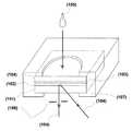
ライケム(富士写真フイルム)、スポットケム(京都第一科学)からシステムが市販されている。構造は富士ドライケムの例を取ると、図1に示すような構造の試薬スライド透明支持体(プラスチックフィルム)(101)上に分析反応に必要な試薬を含有した試薬層(102)がコーティングされている。この試薬層には反応に必要な試薬が調製済みにし、ゲル中に乾燥した状態で保持されている。更にこの上に反射測光を可能にする反射層(103)と検体を均一
に展開させる展開層(104)が積層された4層構造になっている。このフイルムの上面に10μL前後の血漿や血清の検体(105)が展開層に滴下されると、検体は展開層の毛管現象により横方向へ放射状に均一展開し、その後に反射層に浸透する。反射層及びゲルと混合された試薬層は血液成分を吸収し、単位面積あたりに一定量の検体を吸収して保持される。試薬層に吸収された検体と含有された試薬が反応し、検体成分に対応した発色を呈する。この呈色強度を支持体側から、発色に対応した特定の入射光(104)を照射し、反射光(105)の強度を測定することで、検体中の成分濃度を算出している。ここで、(106)はスリット、(107)はプラスチック製マウントである。On the other hand, as a miniaturized blood analyzer, Reftron using the dry chemistry method (Boehringer Mannheim, Germany), Vitros (Johnson & Johnson, USA), Fuji Drychem (Fuji Photo Film), Spotchem (Kyoto Daiichi) The system is commercially available from Science. Taking the example of Fuji Dry Chem as a structure, a reagent layer (102) containing a reagent necessary for an analytical reaction is coated on a transparent support (plastic film) (101) of a reagent slide having a structure as shown in FIG. Yes. In this reagent layer, a reagent necessary for the reaction is prepared and held in the gel in a dry state. Further, a four-layer structure in which a reflection layer (103) that enables reflection photometry and a development layer (104) that uniformly spreads the specimen are laminated thereon. When about 10 μL of plasma or serum specimen (105) is dropped onto the spreading layer on the upper surface of the film, the specimen is uniformly spread radially in the lateral direction by capillary action of the spreading layer, and then permeates the reflection layer. The reagent layer mixed with the reflective layer and the gel absorbs blood components and absorbs and holds a certain amount of specimen per unit area. The specimen absorbed in the reagent layer reacts with the contained reagent, and develops a color corresponding to the specimen component. The color intensity is irradiated from the support side with specific incident light (104) corresponding to color development, and the intensity of the reflected light (105) is measured to calculate the component concentration in the specimen. Here, (106) is a slit, and (107) is a plastic mount.
ドライケミストリー法では、乾燥状態または外観上乾燥した状態で保存された試薬が測定時に液状の試料に出会うとはじめて試薬に含まれるマトリックスにおいて化学反応が進行する検査法であり、予め試薬を調製しておくと、前述した比色法法の血漿または血清と基質緩衝液との厳密な秤量と混合が必要で無くなる大きな利点がある。 The dry chemistry method is an inspection method in which a chemical reaction proceeds in a matrix contained in a reagent only when a reagent stored in a dry state or in a dry state meets a liquid sample at the time of measurement. In other words, there is a great advantage that it is not necessary to strictly measure and mix the plasma or serum with the substrate buffer in the colorimetric method described above.
そこで、本発明は、このような事情に鑑みなされたものであり、石英板や高分子樹脂板などの絶縁材基板に作製した超小型の溝流路に微量(数μL以下)の血液を導入して遠心分離を行い、当該血漿から被険を電気化学センサ用の流路とドライケミストリー用試薬を収納した流路に導入され、ドライケミストリー反応用流路にあっては血漿との反応によって生じる特定の発色の波長と同じ光を導入し、受光することからなる基板構造を提供することを目的とする。 Therefore, the present invention has been made in view of such circumstances, and a very small amount (several μL or less) of blood is introduced into an ultra-small groove channel formed on an insulating substrate such as a quartz plate or a polymer resin plate. Centrifugation is performed, and the plasma is introduced into the flow path for the electrochemical sensor and the flow path for storing the reagent for dry chemistry, and the dry chemistry reaction flow path is generated by reaction with plasma. An object of the present invention is to provide a substrate structure that receives and receives light having the same wavelength as a specific color.
本願第1発明は、上記の課題を解決するために、基板に種々の機能を有するマイクロ
流路を形成し、遠心力を用いて、血液導入口から全血試料を血球・血漿分離用流路に導入し基板内で血漿分画を得て、血漿を案内流路により搬送し、ドライケミストリー用試薬を収納した流路に導入して血漿中の被検成分とドライケミストリー用試薬とを反応させ、特定の測定光を導入し、透過度の変化を受光器により測定することにより血漿中の被検成分する血液分析装置を提供する。In order to solve the above problems, the first invention of the present application forms a micro flow channel having various functions on a substrate, and uses a centrifugal force to remove a whole blood sample from a blood inlet and a blood cell / plasma separation flow channel. The plasma fraction is obtained in the substrate, the plasma is transported by the guide channel, and introduced into the channel containing the dry chemistry reagent to react the test component in the plasma with the dry chemistry reagent. Provided is a blood analyzer that introduces a specific measurement light and measures a change in transmittance with a light receiver to measure a test component in plasma.
本願第2発明は、本願第1発明において、採血針と全血溜め用の管が連結された採血アセンブリを本血液分析装置の基板に設けられた全血導入口に挿入し、採血アセンブリの軸方向の基板の外側に設けた第1の回転軸を中心として回転することにより、全血を血液導入
口から血液案内流路を経て血球・血漿分離用流路に搬送し、更に遠心力を用いて血球分画と血漿分画に分離する装置を提供する。これによって、ポンプによる吸引や外部からの圧力、及びその案内口と管などを必要としないため装置の設計が容易になり、装置の小型化が図れる。The second invention of the present application is the first invention of the present application, wherein the blood collection assembly in which the blood collection needle and the tube for collecting the whole blood are connected is inserted into the whole blood inlet provided in the substrate of the present blood analyzer, and the shaft of the blood collection assembly The whole blood is conveyed from the blood inlet to the blood cell / plasma separation channel through the blood guide channel by rotating around the first rotation axis provided on the outside of the substrate in the direction, and further using centrifugal force An apparatus for separating blood cell fraction and plasma fraction is provided. This eliminates the need for suction by the pump, pressure from the outside, and its guide port and pipe, so that the design of the device is facilitated and the device can be miniaturized.
本願第3発明は、本願第1発明と本願第2発明において、複数の溝からなる流路による血球・血漿用分離流路の構造を提供する。まず、全血導入口は全血搬送案内流路と連結し、全血搬送案内流路は、血液導入口を中心に略円弧に、且つ血液導入口の方向に設けられた複数の溝流路が形成された溝群の血液導入口を見て下方側が連結された一本の溝と連結し、第1の回転軸を中心として回転することにより全血を全血搬送案内流路を経て溝流路に導入し、そのまま回転すると溝流路の下方側に血球分画が収容され、上方側に血漿分画が収容される装置を提供する。
当該溝流路は、特開2001−258868号公報に述べられ、ここでは上方側に上清された血漿中に電気化学バイオセンサーを設けておくことにより直接に被検成分を測定できる特徴がある。本発明を本願に適用すると、概ね秤量された血漿を後続の測定用流路に分配することができる。A third invention of the present application provides a structure of a blood cell / plasma separation flow path by a flow path comprising a plurality of grooves in the first and second inventions of the present application. First, the whole blood introduction port is connected to the whole blood conveyance guide channel, and the whole blood conveyance guide channel is a plurality of groove channels provided in a substantially arc shape around the blood introduction port and in the direction of the blood introduction port. When the blood inlet of the groove group in which the groove is formed is connected, the lower side is connected to a single groove, and the whole blood is passed through the whole blood conveyance guide flow path by rotating about the first rotation axis. When introduced into the flow path and rotated as it is, an apparatus is provided in which a blood cell fraction is accommodated on the lower side of the groove flow path and a plasma fraction is accommodated on the upper side.
The groove channel is described in Japanese Patent Application Laid-Open No. 2001-258868, and here, there is a feature that a test component can be directly measured by providing an electrochemical biosensor in the plasma supernatant on the upper side. . When the present invention is applied to the present application, roughly weighed plasma can be distributed to the subsequent measurement channel.
本願第4発明は、本願第1発明と本願第2発明において、血球・血漿分離流路は、概ねU字状流路、即ちU字が外側にわずかに開いて形成されている流路によって血漿を得る装置を提供している。U字状流路の一端は全血導入口と連結した血液搬送案内流路と連結し、U字状流路下端から前記血液導入口を見て基板の上方に設けられた第1の回転軸を中心とし
て回転することにより全血をU字状流路に導入され、そのまま遠心を続けると、U字状流路下端の湾曲部に血球分画が収容され、その上部には血漿分画が収容される装置を提供している。本願も
本願第5発明は、本願第1発明と本願第3発明を基に、ドライケミストリー法による被検成分の測定する装置を提供している。即ち、本願第3発明に記載の複数の溝流路の他端の各々は血漿案内流路と血漿秤量用血漿溜めとキャピラリバルブと各ドライケミストリー用試薬導入流路がその順番で直列に接続されている。本願第3発明に記載の第2の回転軸
を中心に回転し、遠心力により血漿分画収容部から血漿が、各血漿案内流路を経て、一旦各血漿秤量用血漿溜めに導入される。更に遠心力を増すと秤量された血漿が各キャピラリバルブを経て各ドライケミストリー用試薬導入流路に導入させ、更に秤量されたドライケミストリー用試薬が導入された流路の片側から血漿が遠心力で導入される。ドライケミストリー用試薬は、血漿内に一定の濃度の被検成と、試薬導入流路の長手方向に反応が進む。一連の血漿の搬送はポンプや空気圧を用いずに行われ、装置の動作の簡便さと小型化が達成される。The fifth invention of the present application provides an apparatus for measuring a test component by a dry chemistry method based on the first and third inventions of the present application. That is, each of the other ends of the plurality of groove channels described in the third invention is connected in series with a plasma guide channel, a plasma reservoir for plasma weighing, a capillary valve, and each dry chemistry reagent introduction channel in that order. ing. The plasma is rotated around the second rotation axis described in the third invention of the present application, and the plasma is once introduced into each plasma weighing plasma reservoir through each plasma guide channel by centrifugal force through each plasma guide channel. When the centrifugal force is further increased, the weighed plasma is introduced into each dry chemistry reagent introduction flow path through each capillary valve, and the plasma is further centrifuged by centrifugal force from one side of the flow path where the weighed dry chemistry reagent is introduced. be introduced. In the dry chemistry reagent, the reaction proceeds in the longitudinal direction of the reagent introduction flow path and a constant concentration in the plasma. A series of plasma conveyance is performed without using a pump or air pressure, and the simplicity and miniaturization of the operation of the apparatus are achieved.
本願第6発明は、本願第1発明と本願第4発明を基に、U字状流路の他端の流路に複数
の分岐した血液搬送案内流路が設けられ、当該各流路は血液溜めと秤量用血漿溜めとキャピラリバルブと血漿導入用流路がその順番で直列に同一基板上で接続され、更に、血漿導入用流路の直下に血漿展開層が設けられ、その直下に垂直方向に一致して接合された複数の孔を設けた領域を有する基板と当該孔基板の直下に設けられたドライケミストリー試薬注入比色測定用流路がこの順番で接合されたことによって積層基板が形成された装置を提供している。血漿展開層と複数の孔を設けた領域とドライケミストリー試薬注入比色測定用流路の各面積は等しい。そして、U字状流路と略直交方向で、当該流路から見て基板の
外側に位置する第2の回転軸を中心に回転させると、遠心力によりU字状流路内の血漿をドライケミストリー試薬注入比色測定用流路に導入される。The sixth invention of the present application is based on the first invention of the present application and the fourth invention of the present application, and a plurality of branched blood conveyance guide channels are provided in the flow channel at the other end of the U-shaped flow channel. The reservoir, the plasma reservoir for weighing, the capillary valve, and the plasma introduction flow path are connected in series in that order on the same substrate, and further, a plasma spreading layer is provided directly below the plasma introduction flow path, and a vertical direction is provided directly below the plasma development layer. A substrate having a region provided with a plurality of holes bonded in accordance with the substrate and a dry chemistry reagent injection colorimetric measurement channel provided immediately below the hole substrate are bonded in this order to form a laminated substrate Provided equipment. Each area of the plasma spreading layer, the region provided with the plurality of holes, and the dry chemistry reagent injection colorimetric measurement channel are equal. Then, when rotating around the second rotation axis located outside the substrate when viewed from the flow path in a direction substantially orthogonal to the U-shaped flow path, the plasma in the U-shaped flow path is dried by centrifugal force. It is introduced into the chemistry reagent injection colorimetric channel.
血漿展開流路からの血漿はその下部にある孔を通してドライケミストリー用試薬用流路に導入されるが、その導入に用いる遠心力は孔と直角方向にある。しかし、血漿溜め用流路の遠心力が印加される方向の端が壁となり、また血漿溜め用流路に血漿が満たされているため、遠心力によって圧力を受けた血漿が下部の孔へ導入されることになる。このように遠心力を用いるだけで血漿をドライケミストリー用試薬用流路に導入できる。
本願第7発明は、本願第5発明と本願第6発明の秤量用血漿溜めの上流側の壁に過剰血漿収容溜めを設けた装置を提供する。決った量の血漿を血漿溜めに遠心力で導入する際、過剰な血漿が導入されると、側壁に設けた廃棄血漿搬送案内流路を経て外部の廃棄血漿溜めに廃棄され、秤量用血漿溜めへの正確な血漿量を提供する。Plasma from the plasma development flow path is introduced into the dry chemistry reagent flow path through a hole in the lower part, and the centrifugal force used for the introduction is in a direction perpendicular to the hole. However, the end of the plasma reservoir channel in the direction where the centrifugal force is applied is a wall, and the plasma reservoir channel is filled with plasma, so that the plasma that receives pressure due to the centrifugal force is introduced into the lower hole. Will be. In this way, plasma can be introduced into the dry chemical reagent flow path simply by using centrifugal force.
The seventh invention of the present application provides an apparatus provided with an excess plasma storage reservoir on the upstream wall of the weighing plasma reservoir of the fifth and sixth inventions. When introducing a fixed amount of plasma into the plasma reservoir by centrifugal force, if excessive plasma is introduced, it is discarded to the external waste plasma reservoir via the waste plasma transfer guide channel provided on the side wall, and the plasma reservoir for weighing is used. Provide accurate plasma volume to.
本願第8発明は、本願第5発明と本願第6発明に記載のドライケミストリー用試薬の決った量を流路に収めるために流路へ試薬を注入し、過剰な試薬は排出するため、ドライケミストリー用試薬流路に注入口と排出口を設けたこと装置を提供する。
ドライケミストリー試薬はゲル状で調製され、本願によって一定量のゲルをマイクロ流路に導入することが容易になる。The eighth invention of the present application is such that a reagent is injected into the flow path so that a fixed amount of the dry chemistry reagent according to the fifth and sixth inventions of the present application is contained in the flow path, and excess reagent is discharged. An apparatus is provided in which an inlet and an outlet are provided in a chemistry reagent flow path.
The dry chemistry reagent is prepared in a gel form, and the present application facilitates the introduction of a certain amount of gel into the microchannel.
本願第9発明は、本願第6発明に記載のドライケミストリー試薬比色測定用流路にあっては、長手方向の流路の両端は45度の壁が設けられ、その内部には金属などが塗布され、45度の壁で光が反射するよう基板の下部または上部から垂直に光導入用と射出用ファイバーが導入されたことを特徴とする装置を提供する。 The ninth invention of the present application is the dry chemistry reagent colorimetric measurement channel described in the sixth invention of the present application, in which both ends of the longitudinal channel are provided with 45 degree walls, and a metal or the like is provided in the inside. An apparatus is provided in which light introduction and emission fibers are introduced vertically from the bottom or top of the substrate so that light is reflected by a 45 degree wall.
ドライケミストリー用試薬は、導入血漿中の被検成分やアンモニアと反応して発色や着色するが、その度合いを調べる比色測定用流路において、特定の波長を基板の下部または上部から導入し、流路内を内壁による光吸収などによる減衰が無く伝播させ、発色や着色などの化学反応のみによる導入光の減衰度を検出器により測定し、且つ外部からの迷光の侵入することを防止するため、流路内部には金属などの光漏洩や侵入を防止する材料が塗布され、更に長手方向の流路の両端は45度の壁が設けられ、その付近に光導入用と射出用ファイバーが導入されるため、45度の壁で光が反射して光導入と受光が高効率で行える。 The reagent for dry chemistry reacts with the test components and ammonia in the introduced plasma and develops color or coloration.In the colorimetric measurement channel to check the degree, a specific wavelength is introduced from the lower part or the upper part of the substrate, Propagation without attenuation due to light absorption by the inner wall in the flow path, to measure the attenuation of introduced light due only to chemical reactions such as coloring and coloring with a detector, and to prevent the entry of stray light from the outside The inside of the channel is coated with a material that prevents light leakage and intrusion, such as metal, and both ends of the channel in the longitudinal direction are provided with 45 degree walls, and light introduction and emission fibers are introduced in the vicinity of the walls. Therefore, light is reflected from the 45-degree wall and light can be introduced and received with high efficiency.
本願第10発明は、本願第6発明に記載のドライケミストリー試薬比色測定用流路にあっては、本願第9発明と当該測定用流路の内部を金属など光遮蔽材で覆う点は同じであるが、長手方向の流路の両端は流路軸と一致した両方向に光導入用と射出用ファイバーが導入された装置を提供する。 The tenth invention of the present application is the same as the ninth invention of the present application in that the inside of the measurement flowpath is covered with a light shielding material such as metal in the dry chemistry reagent colorimetric measurement flowpath described in the sixth aspect of the present invention. However, the both ends of the longitudinal flow path provide a device in which light introduction and emission fibers are introduced in both directions that coincide with the flow path axis.
本願第11発明は、本願第6発明に記載のドライケミストリー試薬比色測定用流路にあっては、秤量された一定の血漿がドライケミストリー試薬を含有したゲルが反応して膨潤する際、その膨潤量を予め測定し置き、当該流路をその膨潤した容積で設計・製作された装置を提供する。 The eleventh invention of the present application is the dry chemistry reagent colorimetric measurement flow path described in the sixth invention of the present application. When the weighed constant plasma swells when the gel containing the dry chemistry reagent reacts, An apparatus is provided in which the amount of swelling is measured in advance and the flow path is designed and manufactured with the swollen volume.
本願第12発明は、本願第6発明に記載のドライケミストリー試薬比色測定用流路にあっては、秤量された一定の血漿がドライケミストリー試薬を含有したゲルが反応して膨潤しても、一定の流路容積で設計・製作された装置を提供する。 In the dry chemistry reagent colorimetric measurement flow path according to the sixth invention of the present application, even if the weighed constant plasma reacts with the gel containing the dry chemistry reagent and swells, An apparatus designed and manufactured with a constant flow volume is provided.
ゲルは通常2倍から5倍程度に膨潤するが、本願第11発明では、膨潤した全量に特定光を導入してその減衰度を測定でき、S/N比の大きい測定値が得られるが、逆に減衰度が大
き過ぎて測定が困難になる場合もあり、流路が基板に占める面積が大きくなり基板面積が拡大する。一方、本願第12発明では、大きく膨潤した試薬に対しては、導入試薬が本願第8発明により排出されるため、測定光の減衰度が小さく、S/N比の低い測定になるが、
使用者の被検成分の濃度を予め知っておくことや測定可能なドライケミストリー試薬を調
製しておくことにより、一定容積の流路でも多項目の被検成分濃度の測定が可能になる。現実の基板では両発明を併用する。The gel normally swells about 2 to 5 times. In the eleventh invention of the present application, specific light can be introduced into the entire swollen amount to measure the attenuation, and a measured value with a large S / N ratio can be obtained. Conversely, the attenuation may be too large to make measurement difficult, and the area occupied by the flow path in the substrate increases, increasing the substrate area. On the other hand, in the twelfth invention of the present application, since the introduced reagent is discharged according to the eighth invention of the present invention for the largely swollen reagent, the attenuation of the measurement light is small and the measurement has a low S / N ratio.
By knowing the concentration of the test component of the user in advance and preparing a measurable dry chemistry reagent, it is possible to measure the test component concentration of multiple items even in a fixed volume flow path. In the actual substrate, both inventions are used together.
本願第13発明は、本願第6発明に記載のドライケミストリー試薬比色測定用流路にあって、アンモニアガス発生用ドライケミストリー試薬流路の基板と多数の孔を設けた基板とアンモニアガス検出用発生用発色材導入比色測定用流路は、この順番で垂直方向に一致して積層され、更に他の項目の検出用流路とアンモニア発生用流路が同一基板内に設けた装置を提供する。尿酸やクレアチニンや尿素窒素の測定では、直接測定することは難しく、各酵素と反応した後にアンモニアガスが発生するが、アンモニアガス発生用流路から発生したアンモニアガスは均一にアンモニアガスと反応して発色する試薬が導入された流路に導入されねばならないが、本発明はそれを可能にする。 A thirteenth invention of the present application is the dry chemistry reagent colorimetric measurement flow channel according to the sixth invention of the present application, wherein the substrate of the dry chemistry reagent flow channel for ammonia gas generation, the substrate provided with a large number of holes, and the ammonia gas detection Coloring channels for colorimetric introduction for generation are stacked in the same order in the vertical direction, and a device for detecting other items and for ammonia generation is provided on the same substrate. To do. In the measurement of uric acid, creatinine and urea nitrogen, it is difficult to measure directly, and ammonia gas is generated after reacting with each enzyme, but the ammonia gas generated from the ammonia gas generation flow path uniformly reacts with ammonia gas. Although the color developing reagent must be introduced into the introduced channel, the present invention makes it possible.
本願第14発明は、本願第1発明に記載のドライケミストリー試薬を用いた血漿からの被検成分の測定法に加え、従来の電気化学センサーによる被検成分の測定法が同一積層基板に構成された血液分析装置を提供する。 In the 14th invention of the present application, in addition to the method for measuring a test component from plasma using the dry chemistry reagent described in the 1st invention of the present application, a method for measuring a test component using a conventional electrochemical sensor is configured on the same laminated substrate. A blood analyzer is provided.
一般の診断では、Na+、K+、Ca++、pHなどの測定は必須であるが、これらをドライケミ
ストリー試薬で測定することは困難であり、多項目を同時に採取した血液から同時に被検成分を測定することにより診断の正確さが増す。In general diagnosis, measurement of Na+ , K+ , Ca++ , pH, etc. is indispensable, but it is difficult to measure these with dry chemistry reagents. Measuring the component increases the accuracy of the diagnosis.
以上のように、本発明の血液分析装置は、全血の基板への導入、血球・血漿分離、血漿の秤量、及びドライケミストリー試薬への展開の一連の動作をポンプを一切使わずに遠心力で行い、ドライケミストリー試薬が導入された流路の長手方向の光の減衰を測定することから、極微量血液の血漿中から多項目の被検成分を測定可能とすることが可能な安価・簡便な多項目の血液分析装置を実現できる。 As described above, the blood analyzer of the present invention is a centrifugal force that uses a series of operations of introducing whole blood into a substrate, separating blood cells / plasma, weighing plasma, and deploying to a dry chemistry reagent without using any pump. Measures the attenuation of light in the longitudinal direction of the flow channel into which the dry chemistry reagent is introduced, so that it is possible to measure a large number of test components from a very small amount of blood plasma. A multi-item blood analyzer can be realized.
アンモニアガスの測定には、アンモニアガス発生層と展開層とアンモニアガスと反応して発色層が積層分離構造になっているため、アンモニアガスの高感度測定を可能にした血液分析を実現できる。その結果、アンモニアガス測定を含むドライケミストリー比色法センサーに加え電気化学センサーを併用できるので通常の血液検査項目のほとんどを測定可能になり、ベッドサイドのみならず無痛針の使用により在宅での診断が実現される。 In the measurement of ammonia gas, the color generation layer has a laminated separation structure by reacting with the ammonia gas generation layer, the development layer, and the ammonia gas, so that blood analysis that enables highly sensitive measurement of ammonia gas can be realized. As a result, an electrochemical sensor can be used in combination with a dry chemistry colorimetric sensor that includes ammonia gas measurement, making it possible to measure most of the normal blood test items, and diagnosis at home by using painless needles as well as at the bedside. Is realized.
第1実施態様
図2〜図6は血液検査装置を構成する各積層基板示し、図2は最上層基板(201)、図3
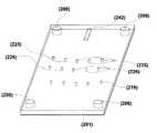
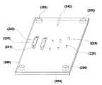
は第2層基板(202)、図4は第3層基板(203)、図5は第4層基板(204)、図6は最下層基板(205)である。各基板は厚さが0.5mmのポリカーボネート製であり、流路や孔は射出成型で形成する。勿論、リソグラフィによって作製したSU-8などのパターンをPET(ポリエチレンテレフタレート)板などの高分子基板にモールドすることによっても作製され、製法に特徴があるものではない。図2〜図6の各積層基板に設けられた孔(206)は、(207)の円柱が孔(206)へ挿入されることによって、最下層基板(205)の上に第4層基板(204)、第4層基板(204)の上に第3層基板(203)、第3層基板(203)の上に第2層基板(202)、そして第2層基板(202)の上に最上層基板(201)が接続され、各基板は接着剤などにより接着される。その結果、各基板に設けられた流路の位置が決められ、各基板間の溶液の流れが可能になる。次に第2層基板(202)について説明する。(208)は外径100μm、内径50μmのステインレス管であり、先端は10度で三面研磨が行われた無痛針を示す。内壁を超平滑化に研磨してあるため、静脈に刺すと、血圧により自動的に採血できる。また(209)は外径250μmのステインレス管であり、(208)と接着されている。(210)は外径1.8mm、内径1mmのガラス管であり、(209)と接着され、無痛針(208)から採取された血液は、ガラス管(210)に溜められる。(211)は基板(202)に加工された血液搬送案内流路であり、第2層基板(202)の第1の回転軸(212)を中心として遠心力を印加すると、複数の血液溜め溝(213)に導入される。更に遠心を続けると、第1の回転軸(212)を見て外側に血球が、内側に血漿が分離される。次に、第2の回転軸(214)を中心に遠心力を印加すると、上清の血漿が血液搬送案内溝(215)を経て秤量用血漿溜め(216)に導入される。その際、導入を可能とするため空気導入孔(217)とその案内溝(218)を設けてある。空気導入孔(217)は、最上層基板(201)の空気導入孔(219)と直結している。秤量用血漿溜め(216)を満たした後の過剰な血漿は過剰血漿案内流路(220)を経て過剰血漿廃棄溜め(221)に捨てられる。更に、第2の回転軸(214)を中心として1000G以上の遠心力を印加すると(216)に秤量用溜めてあった血漿はキャピラリバルブ(222)を介して、基板(202)に設けられた複数の流路に導入される。First Embodiment FIGS. 2 to 6 show laminated substrates constituting a blood test apparatus, FIG. 2 shows an uppermost substrate (201), FIG.
Is a second layer substrate (202), FIG. 4 is a third layer substrate (203), FIG. 5 is a fourth layer substrate (204), and FIG. 6 is a lowermost layer substrate (205). Each substrate is made of polycarbonate with a thickness of 0.5 mm, and the flow paths and holes are formed by injection molding. Of course, it is also produced by molding a pattern such as SU-8 produced by lithography on a polymer substrate such as a PET (polyethylene terephthalate) plate, and the production method is not characteristic. The hole (206) provided in each of the laminated substrates of FIGS. 2 to 6 is formed by inserting the column (207) into the hole (206), so that the fourth layer substrate (205) is formed on the lowermost layer substrate (205). 204), the third layer substrate (203) on the fourth layer substrate (204), the second layer substrate (202) on the third layer substrate (203), and the second layer substrate (202). The uppermost substrate (201) is connected, and each substrate is bonded by an adhesive or the like. As a result, the position of the flow path provided in each substrate is determined, and the solution can flow between the substrates. Next, the second layer substrate (202) will be described. (208) is a stainless tube having an outer diameter of 100 μm and an inner diameter of 50 μm, and shows a painless needle whose tip is subjected to three-side polishing at 10 degrees. Since the inner wall is polished to be ultra-smooth, blood can be collected automatically by blood pressure when inserted into a vein. Further, (209) is a stainless tube having an outer diameter of 250 μm and is bonded to (208). (210) is a glass tube having an outer diameter of 1.8 mm and an inner diameter of 1 mm, which is adhered to (209), and blood collected from the painless needle (208) is stored in the glass tube (210). Reference numeral (211) denotes a blood conveyance guide channel processed into the substrate (202). When a centrifugal force is applied around the first rotation axis (212) of the second layer substrate (202), a plurality of blood reservoir grooves are provided. (213). When the centrifugation is further continued, blood cells are separated on the outside and plasma is separated on the inside as seen from the first rotation axis (212). Next, when a centrifugal force is applied around the second rotating shaft (214), the supernatant plasma is introduced into the weighing plasma reservoir (216) through the blood conveyance guide groove (215). At that time, an air introduction hole (217) and a guide groove (218) are provided to enable introduction. The air introduction hole (217) is directly connected to the air introduction hole (219) of the uppermost substrate (201). Excess plasma after filling the weighing plasma reservoir (216) passes through the excess plasma guide channel (220) and is discarded to the excess plasma waste reservoir (221). Further, when a centrifugal force of 1000 G or more is applied around the second rotation axis (214), the plasma accumulated in the weighing in (216) is provided on the substrate (202) via the capillary valve (222). It is introduced into a plurality of flow paths.
前述のキャピラリバルブに関しては、Nam-Trung Nguyen とSteven T. Wereleyの著作による「Fundamentals and Applications of Microfludics」(発行所:Artech House (Boston・London) 2002)の315ページに述べられている。簡単に説明すると、細管(キャピラリ)に溶液が存在する時、細管の軸方向の一端の延長上に回転軸があり、細管の他端に溶液が表面張力で溜まっているとすると、その回転軸を中心に回転すると、小さい遠心力ではこの溶液は細管の他端からは吐出しないが、遠心力を増していくと遂に表面張力を勝り、溶液が吐出する。従って、遠心力の大小がバルブの働きをするのでキャピラリバルブと呼ぶ。溶液が細管から吐出する最小の回転数fmは、溶液が回転軸から、回転軸側の細管半径R1と吐出側の半径R2の間に存在し、溶液が細管から吐出する時の溶液の細管に対する接触角をθ、表面張力をγ、細管の半径をR、溶液の密度をρとすると、以下の関係にある。The aforementioned capillary valve is described on page 315 of "Fundamentals and Applications of Microfludics" (Publisher: Artech House (Boston, London) 2002), written by Nam-Trung Nguyen and Steven T. Wereley. Briefly, when a solution is present in a capillary (capillary), if there is a rotation axis on the extension of one end in the axial direction of the capillary and the solution is accumulated at the other end of the capillary by surface tension, the rotation axis , The solution does not discharge from the other end of the thin tube with a small centrifugal force, but when the centrifugal force is increased, the surface tension is finally overcome and the solution is discharged. Therefore, since the magnitude of the centrifugal force acts as a valve, it is called a capillary valve. Minimum number of revolutions fm of the solution is discharged from the capillary tube, the solution is rotary shaft, exists between the radius R2 of the capillary radius R1 and the discharge side of the rotary shaft side, the solution is a solution at the time of discharge from the capillary When the contact angle with respect to the capillary is θ, the surface tension is γ, the radius of the capillary is R, and the density of the solution is ρ, the following relationship is established.
fm2>γcosθ/R・ρ・π2・(R2-R1)(R2+R1)
25℃の水のγは72×10-3[N/m]であり、PETを基板として用いた場合、水との接触角θは80度となり、水のρは1×103[kg/m3]なので、これらの値を用いると、この式から、R2を5cm、キャピラリバルブの長さ、つまり(R2-R1)を0.5cm、その直径(2R)を100μm程度に形成すれば、fmが約1000回転/秒以上の時に血漿が秤量用血漿溜めからドライケミストリー試薬流路に流れ込む。この時の重力加速度は60G以上となる。fm2> γcosθ / R ・ ρ ・ π2・ (R2 -R1 ) (R2 + R1 )
The γ of 25 ° C. Water was72 × 10- 3 [N / m ], the case of using the PET as a substrate, the contact angle θ with water becomes 80 degrees, the ρ water 1 × 10³ [kg / m3 ], so using these values, from this equation, R2 is 5 cm, the length of the capillary valve, that is, (R2 -R1 ) is 0.5 cm, and its diameter (2R) is about 100 μm. For example, when fm is about 1000 rpm or more, plasma flows from the weighing plasma reservoir into the dry chemistry reagent flow path. The gravitational acceleration at this time is 60G or more.
ドライケミストリーでは少なくとも2種類の反応系がある。その一つはクレアチニンや
尿素窒素の測定と、他一つはグルコース、γ-GTP、GOT、GPTや総コレステロールなどの測定である。前者の測定は、まずクレアチニンの場合は、クレアチニンデイアミラーゼ、尿素窒素の場合はウレアーゼの各酵素との反応でアンモニア(NH3)ガスが発生し、そのNH3ガスは各々ブロムクレゾールグリーンやブロムフェノールブルーと反応して発色させる2段
階の反応を用いる。一方、上記の他の被検物質は、それぞれの反応に応じての酵素と発色試薬を含有したゲルと一段階の反応で検出する。そこで、(223)はNH3の検出用流路を示し、(224)はNH3以外の検査項目用流路を示し、それぞれ上述のゲルが満たされている。There are at least two types of reaction systems in dry chemistry. One is measurement of creatinine and urea nitrogen, and the other is measurement of glucose, γ-GTP, GOT, GPT and total cholesterol. In the former measurement, ammonia (NH3 ) gas is generated by reaction with each enzyme of creatinine deamylase in the case of creatinine and urease in the case of urea nitrogen, and the NH3 gas is respectively bromocresol green or bromophenol. Use a two-step reaction that reacts with blue to develop color. On the other hand, the other test substances described above are detected by a one-step reaction with a gel containing an enzyme and a coloring reagent according to each reaction. Therefore, (223) shows a flow path for detection of NH3 , and (224) shows a flow path for inspection items other than NH3 , each filled with the above-mentioned gel.
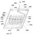
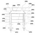
図7は、NH3以外の検査項目用流路を設けた積層基板の構造を示す。最上層基板(201)の
孔(225)と孔(226)は各々、当該ゲルの導入口と排出口であり、導入口の径は排出口の径より大きく、試薬を含有したゲルの導入はマイクロディスペンサーで行われる。導入口と排出口は、(223)と(224)の2つの異なる反応系の流路に注入し、内部を満たした後の余分な
ゲルを排出するためと、血漿がゲル中に遠心力で導入されると、ゲルの種類にもよるが、2〜5倍に膨潤するため、膨潤したゲルを外部に排出するための孔である。また、流路(224)の長手方向の両端には45度の傾斜壁(227)が形成されている。その内壁はアルミ膜がスパッタ蒸着され、第3層基板(203)、第4層基板(204)、最下層基板(205)に貫通孔(228)を設け、その中にファイバー(229)が挿入され、その端面が流路の45度の傾斜壁の下方に留める。アルミ膜(230)を流路(224)の内壁にスパッタ蒸着する方法は、まず最上層基板(201)と第2層基板(202)を接触させ、第2層基板(202)の裏面からアルミをスパッタ蒸着し、流路以外の部分のアルミ膜はCMP(化学的機械研磨)によって除去する。次に、第2層基板(202)から最上層基板(201)を除去して、第2層基板(202)と第3層基板(203)を接触させ、最上層基板(201)の上方からアルミをスパッタ蒸着し、流路以外の部分のアルミ膜はCMPによって除去する。なお、アルミの他、光が流路から外部に逃げず、流路内で効率よく反射する材料であるならば金属の他いかなる材料でも良い。ファイバー(229)には、(231)のハロゲンランプやタングステンランプから(232)のバンドパスフィルターを介して発色した波長の光を導入し、 (233)の受光器によってその減衰度を測定する。FIG. 7 shows the structure of a multilayer substrate provided with a flow path for inspection items other than NH3 . The hole (225) and the hole (226) of the uppermost substrate (201) are the gel inlet and outlet, respectively, and the diameter of the inlet is larger than the diameter of the outlet, and the introduction of the gel containing the reagent is Made with a micro dispenser. The inlet and outlet are injected into the flow paths of two different reaction systems (223) and (224) to discharge excess gel after filling the interior, and the plasma is centrifugally moved into the gel. When introduced, it is a hole for discharging the swollen gel to the outside because it swells 2 to 5 times depending on the type of gel. In addition, inclined walls (227) of 45 degrees are formed at both ends in the longitudinal direction of the channel (224). The inner wall is sputter-deposited with an aluminum film, and through holes (228) are provided in the third layer substrate (203), fourth layer substrate (204), and lowermost layer substrate (205), and a fiber (229) is inserted therein. And its end face stays below the 45 degree inclined wall of the channel. The sputter deposition of the aluminum film (230) on the inner wall of the flow path (224) is performed by first contacting the top layer substrate (201) and the second layer substrate (202) and then starting aluminum from the back surface of the second layer substrate (202). Is sputter-deposited, and the aluminum film other than the flow path is removed by CMP (chemical mechanical polishing). Next, the top layer substrate (201) is removed from the second layer substrate (202), the second layer substrate (202) and the third layer substrate (203) are brought into contact with each other, and the top layer substrate (201) is viewed from above. Aluminum is sputter-deposited, and the aluminum film outside the channel is removed by CMP. In addition to aluminum, any material other than metal may be used as long as light does not escape from the flow path to the outside and is efficiently reflected in the flow path. Into the fiber (229), light having a wavelength developed from a halogen lamp (231) or a tungsten lamp through a bandpass filter (232) is introduced, and the attenuation is measured by a light receiver (233).
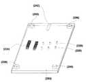
図8は、アンモニアガス検出用の流路(223)を含む多層の流路構造を示す。第3層基板(203)には、アンモニアガスを通す役割の直径5μm〜50μm程度の多数の孔(234)が設けられている。この多数の孔を設けた領域の面積は第2層基板(202)に設けたアンモニアガス発生用試薬を収容された流路(223)と同じ面積を有する。この孔領域(234)はドライケミストリーの展開層の役目も果たす。図4にはその鳥瞰図を示す。当該孔の作成法は、大きい径の場合は、ステインレスや高分子製のメッシュや射出成型で形成可能だが、小さい径の場合はシリコン基板にディープエッチングで形成される。多数の孔(234)を通過したNH3ガスは、第4層基板(204)と最下層基板(205)に形成した図8で述べた流路に導入される。流路内壁へのアルミ膜のコーティング形成法は前述と同様である。流路(235)はアンモニアガスと反応して発色する試薬を含有したゲルが導入される。ここで、(236)は45度の傾斜壁、(237)アルミ膜、(238)ファイバー用貫通孔、(239)はファイバー、(240)と(241)はそれぞれアンモニアガス反応発色試薬含有ゲルの注入孔と排出孔である。ランプ、バンドパスフィルター、受光器などの光学部品の図示は省いた。FIG. 8 shows a multilayer channel structure including a channel (223) for ammonia gas detection. The third layer substrate (203) is provided with a large number of holes (234) having a diameter of about 5 μm to 50 μm for passing ammonia gas. The area of the multiple holes is the same as that of the flow path (223) containing the ammonia gas generating reagent provided on the second layer substrate (202). This pore region (234) also serves as a spreading layer for dry chemistry. FIG. 4 shows a bird's eye view. In the case of a large diameter, the hole can be formed by a stainless or polymer mesh or injection molding, but in the case of a small diameter, the hole is formed by deep etching on a silicon substrate. NH3 gas which has passed through a number of holes (234) is introduced into the flow path described in Figure 8 which is formed on the bottom layer substrate and the fourth layer substrate (204) (205). The method for forming the aluminum film coating on the inner wall of the flow path is the same as described above. The flow path (235) is introduced with a gel containing a reagent that develops color by reacting with ammonia gas. Here, (236) is a 45 degree inclined wall, (237) aluminum film, (238) fiber through hole, (239) is fiber, and (240) and (241) are ammonia gas reaction coloring reagent-containing gels, respectively. An injection hole and a discharge hole. The illustration of optical components such as lamps, bandpass filters and light receivers is omitted.
第2実施態様
図9〜図12は、複数の比色センサーと複数の電気化学センサーを一つの基板に集積化した血液検査装置を構成する各積層基板示す。一般に、診断にとっては基本的に必要なpHやNa+、K+、Cl―、Ca++などイオンの濃度測定も必要であり、pHはアンペロメトリ、Na+とK+とCl―とCa++の各濃度はポテンシオメトリによる電気化学的方法によって測定される。従って、比色センサーと電気化学センサーの両方を一つの基板に集積化し、一度の採血で測定することが望ましい。この比色センサー群にはNH3検出用の比色センサーを構成が煩
雑になるので搭載しなかったが、NH3を検出する場合は、図2〜図6と同様にNH3ガスの発
生層が追加される。Second Embodiment FIGS. 9 to 12 show each laminated substrate constituting a blood test apparatus in which a plurality of colorimetric sensors and a plurality of electrochemical sensors are integrated on one substrate. In general, it is also necessary to measure the concentration of ions such as pH and Na+ , K+ , Cl-, Ca++ which are basically necessary for diagnosis, and the pH is determined by amperometry, Na+ , K+ , Cl- and Ca++ Each concentration of is measured by an electrochemical method using potentiometry. Therefore, it is desirable to integrate both the colorimetric sensor and the electrochemical sensor on a single substrate and perform measurement with a single blood collection. Although this colorimetric sensor group constituting a colorimetric sensor for NH3 detection was not mounted since complicated, when detecting the NH3 is generating layer likewise NH3 gas and Figures 2-6 Is added.
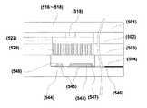
図9は最上層(501)、図10は第2層(502)、図11は第3層(503)、図12は最下層(504)であり4枚の基板からなる。図2〜図6と同様に図9〜図12の各積層基板に設けられた孔(505)は、(506)の円柱が孔(505)へ挿入されることによって、最下層(504)の上に第3層(503)、第3層(503)の上に第2層(502)、そして第2層(502)の上に最上層(501)が接続され、各基板は接着剤などにより接着される。まず、第2層基板(502)では、図3と同様に、無痛針(507)からステインレス管(508)を経て (509)のガラス管に接続され、ガラス管(509)に血液が採取される。採血は、開いた概ねU字管(510)に第1の回転軸(511)を中心に遠心力によって導入され、更に遠心を続けると、第1の回転軸(511)を見て外側に血球分画が、内側に血漿分画が分離され、血球分画は血球溜め(512)に溜められる。(513)は血球がU字管に戻ることを防ぐ柱である。次に、第2の回転軸(514)を中心に遠心力を印加すると、上清の血漿が一旦血漿溜め(515)に導入される。更に、回転を続けると、血漿搬送案内流路(516)を経て、更に60G以上の重力加速度の遠心力によってキャピラリバルブ(517)を通過して血漿秤量用血漿溜め(518)と血漿導入用流路(519)に導入される。その際、血漿秤量 用血漿溜め(518)の側壁に秤量後の余分な血漿を廃棄血漿搬送案内流路(520)を経て 廃棄血漿溜め(521)に廃棄される。血漿導入用流路(519)の直下には血漿展開層(522)が設けられ、一旦血漿を平板上に拡大した。ここで、(523)はドライケミストリー比色法のセンサー領域を示し、(524)は電気化学センサー法センサー領域を示す。電 気化学センサーは測定前に較正しなければならず、(525)は較正液の導入口、(526) は較正液導入案内流路、(527)は較正後廃液案内流路、(528)は較正後廃液の廃液口を示す。 9 is the uppermost layer (501), FIG. 10 is the second layer (502), FIG. 11 is the third layer (503), and FIG. 12 is the lowermost layer (504). 2 to 6, the hole (505) provided in each of the laminated substrates of FIGS. 9 to 12 is inserted into the hole (505) by inserting the column (506) into the hole (505). The third layer (503) is connected to the upper layer, the second layer (502) is connected to the third layer (503), and the uppermost layer (501) is connected to the second layer (502). Is adhered by. First, in the second layer substrate (502), as in FIG. 3, the painless needle (507) is connected to the glass tube (509) via the stainless tube (508), and blood is collected in the glass tube (509). Is done. The blood sample is introduced into the open generally U-shaped tube (510) by centrifugal force about the first rotation axis (511), and further centrifugally continues, the blood cells appear outside as viewed from the first rotation axis (511). The fraction is separated into the plasma fraction on the inside, and the blood cell fraction is stored in a blood cell reservoir (512). (513) is a pillar that prevents blood cells from returning to the U-tube. Next, when a centrifugal force is applied around the second rotation shaft (514), the supernatant plasma is once introduced into the plasma reservoir (515). Further, if the rotation continues, it passes through the plasma conveyance guide channel (516), and further passes through the capillary valve (517) by the centrifugal force of gravitational acceleration of 60 G or more to pass the plasma weighing plasma reservoir (518) and the plasma introduction flow. Introduced to Road (519). At that time, excess plasma after weighing on the side wall of the plasma weighing plasma reservoir (518) is discarded to the discarded plasma reservoir (521) via the discarded plasma transfer guide channel (520). A plasma spreading layer (522) was provided immediately below the plasma introduction channel (519), and the plasma was once expanded on a flat plate. Here, (523) shows the sensor region of the dry chemistry colorimetric method, and (524) shows the sensor region of the electrochemical sensor method. The electrochemical sensor must be calibrated before measurement, (525) is the calibration solution inlet, (526) is the calibration solution introduction guide channel, (527) is the waste solution guide channel after calibration, (528) Indicates the waste liquid outlet of the waste liquid after calibration.
図11に示すように、血漿展開層(522)の直下に、第3層(503)に図4と同様に直径5μm
〜50μm程度の多数の孔を設けた領域(529)を形成し、この領域の面積と位置は血漿展開層(522)と一致させる。ここで、(530)はドライケミストリー比色法のセンサー領域を示し、(531)は電気化学センサー法センサー領域を示す。As shown in FIG. 11, just below the plasma spreading layer (522), the third layer (503) has a diameter of 5 μm as in FIG.
A region (529) having a large number of holes of about ˜50 μm is formed, and the area and position of this region are matched with the plasma spreading layer (522). Here, (530) indicates the sensor region of the dry chemistry colorimetric method, and (531) indicates the sensor region of the electrochemical sensor method.
図12に示すように、最下層(504)には、血漿展開層(522)の直下の同位置に、同面積のドライケミストリー試薬注入比色測定用流路(532)、(533)、(534)、(535)が接合される。これらの流路の内壁は、図7で述べた方法に準じてアルミなどの光を反射させる金属がコ
ートされている。(536)と(537)はそれぞれドライケミストリー試薬の注入口と排出口である。ドライケミストリー試薬注入比色測定用流路(531)の長手方向の側壁の一端には測定
光の入射口(538)と他端には流路を伝播した後の射出口(539)が設けられ、各口にはファイバー(540)と(541)が接続され、測定光の入射と受光光への射出の役割を果たす。両ファイバーはドライケミストリー試薬注入比色測定用流路(532)〜(535)の長手方向の中心軸と一致して基板(504)に設けられる。試薬の発色による導入光の減衰度を光ダイオードなどに
よるフォトディテクターにより検出する。As shown in FIG. 12, the lowest layer (504) has a dry chemistry reagent injection colorimetric measurement channel (532), (533), (533) of the same area at the same position directly under the plasma spreading layer (522). 534) and (535) are joined. The inner walls of these channels are coated with a metal that reflects light, such as aluminum, according to the method described in FIG. (536) and (537) are an inlet and an outlet for the dry chemistry reagent, respectively. One end of the side wall in the longitudinal direction of the dry chemistry reagent injection colorimetric measurement flow path (531) is provided with a measurement light incident port (538) and the other end is provided with an exit port (539) after propagating through the flow path. Fibers (540) and (541) are connected to each port, and play roles of incident measurement light and emission to received light. Both fibers are provided on the substrate (504) so as to coincide with the central axis in the longitudinal direction of the dry chemistry reagent injection colorimetric measurement channels (532) to (535). The attenuation of the introduced light due to the color of the reagent is detected by a photodetector such as a photodiode.
血漿展開流路(522)からの血漿はその直下にある多数の孔が形成された領域(529)を通してドライケミストリー用試薬用流路(532)〜(535)と電気化学センサー領域(542)に導入
されるが、その導入に用いる遠心力は孔と直角方向にあり、垂直方向には遠心力が働かない。しかし、血漿溜め用流路の遠心力が印加される方向の端が壁となり、また血漿溜め用流路に血漿が満たされているため、遠心力によって圧力を受けた血漿が下部の孔へ導入されることになる。このように遠心力を用いるだけで血漿をドライケミストリー用試薬用流路(532)〜(535)と電気化学センサー領域(542)に導入できる。Plasma from the plasma development channel (522) passes through the region (529) in which a large number of pores are formed immediately below it to the channel (532) to (535) for the dry chemistry reagent and the electrochemical sensor region (542). Although introduced, the centrifugal force used for the introduction is in a direction perpendicular to the hole, and no centrifugal force acts in the vertical direction. However, the end of the plasma reservoir channel in the direction where the centrifugal force is applied is a wall, and the plasma reservoir channel is filled with plasma, so that the plasma that receives pressure due to the centrifugal force is introduced into the lower hole. Will be. In this way, plasma can be introduced into the dry chemistry reagent flow paths (532) to (535) and the electrochemical sensor region (542) only by using centrifugal force.
(532)〜(535)の流路の長手方向の長さが異なって示されている理由を以下に述べる。試薬をゲルに分散させる際、試薬とゲルとを馴染ませるためには各試薬に適したゲルが必要であるが、各種のゲルが血漿と反応するとゲルの膨潤度が異なり、通常、ゲルは通常2倍
から約5倍程度に膨潤する。そこで、ドライケミストリー用試薬用流路(532)〜(535)は、
秤量され供給された血漿と最大限にゲルと反応させるため最適な長さで設計されなければならない。試薬を含有したゲルの注入口と排出口の(536)と(537)は、流路の容積を越えて膨潤したゲルを外部に排出する役目も果たしている。しかし、膨潤した全量に特定光を導入してその減衰度を測定でき、S/N比の大きい測定値が得られるが、逆に減衰度が大き過
ぎて測定が困難になる場合もあり、流路が基板に占める面積が大きくなり基板面積が拡大する。The reason why the lengths in the longitudinal direction of the flow paths (532) to (535) are shown differently will be described below. When dispersing the reagent in the gel, a gel suitable for each reagent is required to mix the reagent and the gel. However, when various gels react with plasma, the degree of swelling of the gel differs. Swells about 2 to 5 times. Therefore, the reagent flow paths for dry chemistry (532) to (535) are
It must be designed with an optimal length to allow maximum reaction with the weighed and supplied plasma with the gel. The inlets and outlets (536) and (537) of the gel containing the reagent also serve to discharge the gel swollen beyond the volume of the channel. However, the attenuation can be measured by introducing specific light into the entire swollen volume, and a measurement value with a large S / N ratio can be obtained, but conversely, the attenuation may be too large to make measurement difficult. The area that the path occupies on the substrate increases and the substrate area increases.
一方、図3におけるNH3の検出用流路(223)とNH3以外の検査項目用流路(224)は同じ面積と体積で示した。大きく膨潤した試薬に対しては、導入試薬が排出孔から排出されるため、測定光の減衰度が小さく、S/N比の低い測定になるが、使用者の被検成分の濃度を予め知っておくことや測定可能なドライケミストリー試薬を調製しておくことにより、一定容積の流路でも多項目の被検成分濃度の測定が可能になる。現実の基板では両発明を併用する。On the other hand, a detection flow channel (223) and NH3 than the inspection items for passage of NH3 in FIG. 3 (224) showed the same area and volume. For highly swollen reagents, the introduced reagent is discharged from the discharge hole, so the measurement light attenuation is small and the S / N ratio is low, but the user knows the concentration of the analyte in advance. In addition, by preparing a dry chemistry reagent that can be measured, it is possible to measure the concentration of a plurality of test components even in a constant volume flow path. In the actual substrate, both inventions are used together.
(542)は電気化学センサー領域である。(543)はAg/AgCl電極であり、その上にNa+やK+
イオン用のイオノフォアを含むセンサー膜が塗布されている。(544)はKCl飽和Ag/AgCl参照電極であり、これらの電極は銀カーボン配線(545)に設けられ、(546)は信号取り出し用の外部電極である。(542) is the electrochemical sensor region. (543) is an Ag / AgCl electrode on which Na+ and K+
A sensor membrane containing an ionophore for ions is applied. (544) is a KCl saturated Ag / AgCl reference electrode, these electrodes are provided on the silver carbon wiring (545), and (546) is an external electrode for signal extraction.
図13は電気化学センサー領域(542)の図12に一点斜線で示した構造の断面を示す。
電気化学センサーは血漿導入前にまず較正される。その後、第2層(502)に設けられた血
漿搬送案内流路(516)を経て、更に60G以上の重力加速度の遠心力によってキャピラリバルブ(517)を通過して血漿秤量用血漿溜め(518)と血漿導入用流路(519)と血漿展開層(522)に導入され、多数の孔が形成された領域(529)を通して電気化学センサー領域(542)に導入される。ここで、(547)はイオノフォア膜、(548)はKCl飽和Ag/AgCl参照電極のKClが電解液に溶失するのを防止する膜である。FIG. 13 shows a cross section of the electrochemical sensor region (542) shown in FIG.
The electrochemical sensor is first calibrated before plasma introduction. Thereafter, it passes through the plasma conveyance guide channel (516) provided in the second layer (502), and further passes through the capillary valve (517) by the centrifugal force of gravitational acceleration of 60 G or more, and the plasma reservoir for plasma weighing (518) And introduced into the plasma introduction channel (519) and the plasma spreading layer (522), and introduced into the electrochemical sensor region (542) through the region (529) in which a large number of holes are formed. Here, (547) is an ionophore film, and (548) is a film for preventing KCl of the KCl saturated Ag / AgCl reference electrode from being dissolved into the electrolyte.
第1実施例
<グルコース測定>
図2〜図6を基にした血液分析装置を用いて、グルコース測定を行った例を示す。測定
原理は、試料に発色試薬を作用させると、試料中のグルコースは発色試薬中に含まれるムタロターゼの作用によりα型からβ型へすみやかに変換する。β-D-グルコースは、グル
コースオキシダーゼ(GOD)の作用を受けて酸化され、同時に過酸化水素を生じる。生成し
た過酸化水素は、共存するペルオキシダーゼ(POD)の作用により、発色試薬中のフェノー
ルと4-アミノアンチピリンとを定量的に酸化縮合させ、赤色(505nm)の色素を生成させる
。この赤色の吸光度を測定することにより試料中のグルコース濃度を求める。The first embodiment <glucose measurement>
The example which performed the glucose measurement using the blood analyzer based on FIGS. 2-6 is shown. The measurement principle is that when a coloring reagent is allowed to act on a sample, glucose in the sample is quickly converted from α-type to β-type by the action of mutarotase contained in the coloring reagent. β-D-glucose is oxidized by the action of glucose oxidase (GOD) and simultaneously produces hydrogen peroxide. The produced hydrogen peroxide quantitatively oxidizes and condenses phenol and 4-aminoantipyrine in the coloring reagent by the action of coexisting peroxidase (POD) to produce a red (505 nm) dye. The glucose concentration in the sample is obtained by measuring the red absorbance.
ドライケミストリー試薬として、(1)黒かびAspergilius niger由来のグルコースオキシダーゼを1.8U、(2)1,7-ジヒドロオキシナフタレンを0.03mg(0.188μmol)、(3)4-アミノアンチピリンを0.1mg(0.492μmol)、(4)ペルオキシダーゼを0.13U、(5)ムタロターゼ(ブタ腎臓由来)を0.065Uの粉末を混合し、燐酸緩衝液に溶解させる。次に、その溶解液をゼラチンに全てを含有させ、ゼラチンゲルを形成する。これをドライケミストリー試薬注入比色測定用流路に注入する。当該比色測定用流路は0.4mm×0.4mmの断面積で長さは1mmであ
った。その中に前述のゲルを注入し、更に0.2μLのブドウ糖標準液をグルコース濃度を0mg/dlから600mg/dlに変化させた。この流路に505nmの光を入射させて得られた吸光度を図14に示す。この結果より良好に検出されたことが分かる。As dry chemistry reagents, (1) 1.8 U of glucose oxidase from Aspergilius niger, (2) 0.03 mg (0.188 μmol) of 1,7-dihydrooxynaphthalene, (3) 0.1 mg (0.492 of 4-aminoantipyrine) μmol), (4) 0.13 U of peroxidase, and (5) 0.065 U of mutarotase (derived from porcine kidney) are mixed and dissolved in a phosphate buffer. Next, all of the solution is contained in gelatin to form a gelatin gel. This is injected into the dry chemistry reagent injection colorimetric channel. The colorimetric measurement channel had a cross-sectional area of 0.4 mm × 0.4 mm and a length of 1 mm. The aforementioned gel was injected into the solution, and the glucose concentration of 0.2 μL glucose standard solution was changed from 0 mg / dl to 600 mg / dl. FIG. 14 shows the absorbance obtained by allowing light of 505 nm to enter this channel. It turns out that it detected more favorably than this result.
第2実施例
<尿素窒素測定>
図7〜図12を基にした血液分析装置を用いて、尿素窒素測定を行った例を示す。Second Example <Urea Nitrogen Measurement>
The example which performed urea nitrogen measurement using the blood analyzer based on FIGS. 7-12 is shown.
尿素窒素(H2NCONH2)は水の存在下でウレアーゼの作用でNH3とCO2に分解され、このNH3
はブロムクレゾールグリーンと反応して青色(620nm)色素を生じる。尿素測定は以下のよ
うに測定された。デンプンーアクリルニトリルからなる吸水性ポリマー10mgに2mLのウレ
アーゼ溶液を含ませたゲル状のものを0.4mm×0.4mmの断面積で長さは1mmのNH3発生用流路に注入した。発色剤は、エタノール2mLにブロムクレゾールグリーン(BCG)3%(重量比)を溶いたものに、イソプロビルアルコール20mLとその5%重量比のPVB(ポリビニールブチラール)1.28mgを合わせて溶かし込んだものを調製し、発色用流路に注入した。多数の孔が形成された基板の厚さは1.2mmであった。図15は、10mgから50mgの尿素標準液を作製し、620nmの光を入射したときの吸光度を示す。この結果より良好に検出されたことが分かる。Urea nitrogen (H2 NCONH2 ) is decomposed into NH3 and CO2 by the action of urease in the presence of water, and this NH3
Reacts with bromcresol green to give a blue (620 nm) dye. The urea measurement was measured as follows. A gel-like material in which 2 mL of urease solution was added to 10 mg of a water-absorbing polymer consisting of starch-acrylonitrile was injected into a NH3 generating flow path having a cross-sectional area of 0.4 mm × 0.4 mm and a length of 1 mm. The color former was dissolved in 2 mL of ethanol with 3% (weight ratio) of bromocresol green (BCG) dissolved in 20 mL of isopropyl alcohol and 1.28 mg of PVB (polyvinyl butyral) at 5% weight ratio. A sample was prepared and injected into the color developing channel. The thickness of the substrate on which many holes were formed was 1.2 mm. FIG. 15 shows the absorbance when a 10 to 50 mg urea standard solution is prepared and 620 nm light is incident. It turns out that it detected more favorably than this result.
101試薬スライド透明支持体(プラスチックフィルム)
102分析反応に必要な試薬を含有した試薬層
103反射層
104展開層
105血漿や血清の検体
106スリット
107プラスチック製マウント
201最上層基板
202第2層基板
203第3層基板
204第4層基板
205最下層基板
206基板接続用孔
207基板接続用孔を貫通する円柱
208ステインレス管製針
209ステインレス管
210ガラス管
211血液搬送案内流路
212第1の回転軸
213複数の血液溜め溝
214第2の回転軸
215血液搬送案内溝
216秤量用血漿溜め
217空気導入孔
218案内溝
219空気導入孔
220過剰血漿案内流路
221過剰血漿廃棄溜め
222キャピラリバルブ
223アンモニアガスの検出用流路
224アンモニアガス以外の検査項目用流路
225ゲルの導入口
226ゲルの排出口
22745度の傾斜壁
228貫通孔
229ファイバー
230アルミ膜
231ハロゲンランプやタングステンランプ
232バンドパスフィルター
233受光器
234多数の孔
235アンモニアガス反応発色剤含有流路
23645度の傾斜壁
237アルミ膜
238ファイバー用貫通孔
239ファイバー
240注入孔
241排出孔
242ガラス管挿入孔
501最上層
502第2層
503第3層
504最下層
505基板接続用貫通孔
506貫通孔に挿入される円柱
507無痛針
508ステインレス管
509ガラス管
510概ねU字管
511第1の回転軸
512血球溜め
513血球逆流防止用柱
514第2の回転軸
515血漿溜め
516血漿搬送案内流路
517キャピラリバルブ
518血漿秤量用血漿溜め
519血漿導入用流路
520廃棄血漿搬送案内流路
521廃棄血漿溜め
522血漿展開層
523ドライケミストリー比色法のセンサー領域
524電気化学センサー法センサー領域
525較正液の導入口
526較正液導入案内流路
527較正後廃液案内流路
528廃液口
529多数の孔を設けた領域
530ドライケミストリー比色法のセンサー領域
531電気化学センサー法センサー領域
532ドライケミストリー試薬注入比色測定用流路
533ドライケミストリー試薬注入比色測定用流路
534ドライケミストリー試薬注入比色測定用流路
535ドライケミストリー試薬注入比色測定用流路
536注入口
537排出口
538測定光の入射口
539射出口
540ファイバー
541ファイバー
542電気化学センサー領域
543Ag/AgCl電極
544KCl飽和Ag/AgCl参照電極
545銀カーボン配線
546信号取り出し用の外部電極
547イオノフォア膜
548KCl溶失防止膜
549 ガラス管挿入孔
101 reagent slide transparent support (plastic film)
102 Reagent layer containing reagents necessary for analytical reaction
103 reflective layer
104 deployment layers
105 Plasma and serum samples
106 slits
107 plastic mount
201 Top layer substrate
202 2nd layer substrate
203 3rd layer substrate
204 4th layer substrate
205 bottom layer substrate
206 Hole for board connection
Cylinder penetrating through hole for connecting 207 board
208 Stainless tube needle
209 stainless tube
210 glass tube
211 Blood transfer guide channel
212 1st axis of rotation
213 Multiple blood reservoirs
214 2nd axis of rotation
215 Blood transport guide groove
216 Weighing plasma reservoir
217 Air introduction hole
218 guide groove
219 Air introduction hole
220 excess plasma guide channel
221 excess plasma waste reservoir
222 capillary valve
223 Ammonia gas detection channel
224 Flow path for inspection items other than ammonia gas
225 gel inlet
226 gel outlet
22745 degree inclined wall
228 through hole
229 fibers
230 aluminum membrane
231 halogen lamp or tungsten lamp
232 band pass filter
233 receiver
234 multiple holes
235 Ammonia gas reactive colorant containing flow path
23645 degree inclined wall
237 aluminum film
238 Fiber through hole
239 fibers
240 injection holes
241 discharge hole
242 glass tube insertion hole
501 top layer
502 2nd layer
503 3rd layer
504 lowest layer
505 substrate through hole
Cylinder inserted into 506 through hole
507 painless needle
508 stainless tube
509 glass tube
510 U-tube
511 first rotation axis
512 blood cell reservoir
513 Blood cell backflow prevention column
514 Second rotation axis
515 plasma reservoir
516 Plasma transfer guide channel
517 capillary valve
518 Plasma reservoir for plasma weighing
519 Plasma flow channel
520 Waste plasma transfer guide channel
521 Waste plasma reservoir
522 Plasma spreading layer
523 sensor area for dry chemistry colorimetry
524 Electrochemical Sensor Method Sensor Area
525 Calibration solution inlet
526 Calibration solution introduction guide channel
527 Waste liquid guide channel after calibration
528 liquid outlet
529 Area with many holes
530 dry chemistry colorimetric sensor area
531 Electrochemical Sensor Method Sensor Area
532 Dry Chemistry Reagent Injection Colorimetric Channel
533 Dry Chemistry Reagent Injection Colorimetric Channel
534 Dry Chemistry Reagent Injection Colorimetric Channel
535 Dry Chemistry Reagent Injection Colorimetric Channel
536 inlet
537 outlet
538 Measuring light entrance
539 outlet
540 fibers
541 fiber
542 electrochemical sensor area
543Ag / AgCl electrode
544KCl saturated Ag / AgCl reference electrode
545 silver carbon wiring
546 External electrode for signal extraction
547 Ionophore membrane
548KCl anti-fouling film
549 Glass tube insertion hole
Claims (14)
Translated fromJapanese口から血液案内流路を経て血球・血漿分離用流路に搬送し、血球分画と血漿分画に分離することを特徴とする請求項1の血液分析装置。A blood collection needle connected to the blood introduction port and a collected blood reservoir are connected to the blood introduction port, and the blood introduction port is connected to a blood cell / plasma separation channel via a whole blood conveyance guide channel to separate blood cells / plasma. The whole blood is transported from the blood inlet to the blood cell / plasma separation channel through the blood guide channel by rotating upward about the first rotation axis as seen from the blood channel through the blood channel. The blood analyzer according to claim 1, wherein the blood analyzer is separated into a plasma fraction and a plasma fraction.
転軸を中心として回転することにより全血を、当該溝流路の下方側に血球分画を収容し、上方側に血漿分画を収容することを特徴とする請求項1または2の血液分析装置。The whole blood conveyance guide channel and the blood cell / plasma separation channel are provided below the blood introduction port, and the blood cell / plasma separation channel is substantially arc-shaped around the blood introduction port and the blood introduction port. A plurality of groove channels are provided, and the lower side is connected by a single channel when viewed from the blood inlet of the groove channel, and the whole blood is recovered by rotating around the first rotation axis. The blood analyzer according to claim 1 or 2, wherein a blood cell fraction is accommodated in a lower side of the groove channel and a plasma fraction is accommodated in an upper side.
搬送案内流路と連結し、U字状流路下端から前記血液導入口を見て基板の上方に設けられ
た第1の回転軸を中心として回転することにより全血を、U字状流路に導入し、U字状流路
下端の湾曲部には前記血球分画収容部が設けられ、その上部が血漿分画収容部とされていることを特徴とする請求項1または2の血液分析装置。The blood cell / plasma separation flow path is generally formed by a U-shaped flow path, one end is connected to a blood conveyance guide flow path connected to the whole blood introduction port, and the blood introduction port is viewed from the lower end of the U-shaped flow channel. Whole blood is introduced into the U-shaped channel by rotating around a first rotation axis provided above the substrate, and the blood cell fraction storage unit is provided at the curved portion at the lower end of the U-shaped channel. The blood analysis apparatus according to claim 1 or 2, wherein the blood analysis apparatus is provided and has an upper part serving as a plasma fraction storage unit.
、遠心力により血漿分画収容部から血漿が、各血漿案内流路と各血漿案内流路と各血漿秤量用血漿溜めと各キャピラリバルブを経て各ドライケミストリー用試薬導入流路に導入することを特徴とする血液分析装置。4. The blood analyzer according to claim 3, wherein each of the other ends of the plurality of groove channels includes a plasma guide channel, a plasma reservoir for plasma weighing, a capillary valve, and a reagent introduction channel for each dry chemistry in that order. Connected in series and rotated around a second rotating shaft provided outside the plurality of groove channels on the lower side, the plasma flows from the plasma fraction storage unit by centrifugal force, and each plasma guide channel and each plasma guide A blood analyzer, which is introduced into each dry chemistry reagent introduction channel via a channel, each plasma weighing plasma reservoir, and each capillary valve.
案内流路が設けられ、当該各流路は血液溜めと秤量用血漿溜めとキャピラリバルブと当該血漿秤量用血漿溜めと血漿導入用流路がその順番で直列に接続され、血漿導入用流路の直下に血漿展開層が設けられ、当該血漿展開層の直下に垂直方向に一致して接合された血漿展開層と同面積の複数の孔を設けた領域を有する基板と当該孔基板の直下に設けられた血漿展開層と同面積のドライケミストリー試薬注入比色測定用流路がこの順番で接合されたことにより形成された積層基板を、U字状流路と略直交方向で、当該流路から見て基板の
外側に位置する第2の回転軸を中心に回転させ、遠心力によりU字状流路内の血漿をドライケミストリー試薬注入比色測定用流路に導入することを特徴とする血液分析装置。5. The blood analyzer according to claim 4, wherein a plurality of branched blood conveyance guide channels are provided in the flow channel at the other end of the U-shaped flow channel, and each of the flow channels includes a blood reservoir, a plasma reservoir for weighing, and a capillary. A valve, a plasma reservoir for plasma weighing, and a plasma introduction flow path are connected in series in that order, and a plasma spreading layer is provided immediately below the plasma introduction flow path. A substrate having a region having a plurality of holes having the same area as the plasma spreading layer joined together, and a dry chemistry reagent injection colorimetric measurement channel having the same area as the plasma spreading layer provided immediately below the hole substrate. The laminated substrate formed by joining in order is rotated around the second rotation axis located outside the substrate when viewed from the flow channel in a direction substantially orthogonal to the U-shaped flow channel, and centrifugal force To dry the plasma in the U-shaped flow path for dry chemistry reagent injection colorimetric measurement A blood analyzer characterized by being introduced into a road.
2. The blood analyzer according to claim 1, wherein a colorimetric sensor and an electrochemical sensor using a dry chemistry reagent are provided in a blood analyzer composed of a laminated substrate.
Priority Applications (4)
| Application Number | Priority Date | Filing Date | Title |
|---|---|---|---|
| JP2004238910AJP2006058093A (en) | 2004-08-18 | 2004-08-18 | Blood analyzer |
| PCT/JP2005/015376WO2006019182A1 (en) | 2004-08-18 | 2005-08-18 | Hemanalysis device |
| DE112005001985TDE112005001985T5 (en) | 2004-08-18 | 2005-08-18 | Device for blood analysis |
| US11/660,162US20080138890A1 (en) | 2004-08-18 | 2005-08-18 | Blood Analysis Apparatus |
Applications Claiming Priority (1)
| Application Number | Priority Date | Filing Date | Title |
|---|---|---|---|
| JP2004238910AJP2006058093A (en) | 2004-08-18 | 2004-08-18 | Blood analyzer |
Publications (1)
| Publication Number | Publication Date |
|---|---|
| JP2006058093Atrue JP2006058093A (en) | 2006-03-02 |
Family
ID=35907564
Family Applications (1)
| Application Number | Title | Priority Date | Filing Date |
|---|---|---|---|
| JP2004238910APendingJP2006058093A (en) | 2004-08-18 | 2004-08-18 | Blood analyzer |
Country Status (4)
| Country | Link |
|---|---|
| US (1) | US20080138890A1 (en) |
| JP (1) | JP2006058093A (en) |
| DE (1) | DE112005001985T5 (en) |
| WO (1) | WO2006019182A1 (en) |
Cited By (12)
| Publication number | Priority date | Publication date | Assignee | Title |
|---|---|---|---|---|
| JP2007259762A (en)* | 2006-03-28 | 2007-10-11 | Univ Of Tsukuba | Microanalyzer and method for analyzing microsample |
| WO2007116909A1 (en)* | 2006-04-04 | 2007-10-18 | Panasonic Corporation | Panel for analyzing sample liquid |
| WO2007136057A1 (en)* | 2006-05-24 | 2007-11-29 | Kyoto University | Microchannel for separating blood plasma |
| JP2009063462A (en)* | 2007-09-07 | 2009-03-26 | Sony Corp | Optical measuring instrument and particulate analyzer |
| JP2010181253A (en)* | 2009-02-05 | 2010-08-19 | Kowa Co | Microchemical chip device |
| JP2011237224A (en)* | 2010-05-07 | 2011-11-24 | Sumitomo Bakelite Co Ltd | Microchannel device |
| JP2012013552A (en)* | 2010-06-30 | 2012-01-19 | Brother Ind Ltd | Inspection object acceptor |
| KR101339118B1 (en) | 2008-02-19 | 2014-01-02 | 한국과학기술원 | Apparatus for examining fluids |
| JP2019120556A (en)* | 2017-12-28 | 2019-07-22 | 国立研究開発法人産業技術総合研究所 | Assay device |
| JP2019120557A (en)* | 2017-12-28 | 2019-07-22 | 国立研究開発法人産業技術総合研究所 | Assay device |
| WO2020090581A1 (en)* | 2018-10-30 | 2020-05-07 | アルプスアルパイン株式会社 | Flow path plate, analysis device, and analysis method |
| WO2024214253A1 (en)* | 2023-04-13 | 2024-10-17 | セルスペクト株式会社 | Blood test aid |
Families Citing this family (17)
| Publication number | Priority date | Publication date | Assignee | Title |
|---|---|---|---|---|
| US9243043B2 (en)* | 2004-04-02 | 2016-01-26 | Dsm Ip Assets B.V. | Filamentous fungal mutants with improved homologous recombination efficiency |
| US20070027383A1 (en)* | 2004-07-01 | 2007-02-01 | Peyser Thomas A | Patches, systems, and methods for non-invasive glucose measurement |
| DE102007038773A1 (en) | 2007-08-16 | 2009-03-12 | Zf Friedrichshafen Ag | Method for carrying out a traction-interrupted circuit in a parallel hybrid vehicle |
| JP5728217B2 (en)* | 2010-12-14 | 2015-06-03 | ローム株式会社 | Microchip and inspection or analysis method using the same |
| US20130211289A1 (en) | 2012-01-25 | 2013-08-15 | Tasso, Inc. | Handheld Device for Drawing, Collecting, and Analyzing Bodily Fluid |
| EP3022548B1 (en) | 2013-07-16 | 2025-04-23 | Freespira, Inc. | Methods and systems for quantitative colorimetric capnometry |
| CN106999120B (en)* | 2014-08-01 | 2021-05-14 | 塔索公司 | Devices, systems, and methods for gravity-enhanced microfluidic collection, handling, and delivery of liquids |
| US10779757B2 (en)* | 2014-08-01 | 2020-09-22 | Tasso, Inc. | Devices, systems and methods for gravity-enhanced microfluidic collection, handling and transferring of fluids |
| CN106501499B (en) | 2015-09-07 | 2019-12-17 | 埃克西亚斯医药有限公司 | Movable measuring unit |
| US11331665B2 (en) | 2016-01-18 | 2022-05-17 | The Board Of Trustees Of The Leland Stanford Junior University | Paperfuge: An integrated paper-based centrifugation and microfluidics platform for low-cost diagnostics |
| DE102016121764A1 (en)* | 2016-11-14 | 2018-05-17 | Testo SE & Co. KGaA | Microfluidic processing chamber and associated method |
| CN110124758B (en)* | 2019-05-12 | 2024-03-19 | 南京岚煜生物科技有限公司 | Sample injection cavity of micro-fluidic chip and single-index micro-fluidic chip |
| USD975312S1 (en) | 2020-02-14 | 2023-01-10 | Beckman Coulter, Inc. | Reagent cartridge |
| WO2021206752A1 (en)* | 2020-04-08 | 2021-10-14 | Indiana Biosciences Research Institute, Inc. | System and method for sensing, capture and release of biomolecules or cells |
| US12030045B1 (en) | 2023-01-05 | 2024-07-09 | Sequitur Health Corp. | Devices, methods, and systems for deriving ammonia gas from whole blood |
| US12140534B2 (en) | 2023-01-05 | 2024-11-12 | Sequitur Health Corp. | Devices, methods, and systems for deriving a permeate from a feed solution |
| CN117960258A (en)* | 2023-11-07 | 2024-05-03 | 四川大学 | Integrated micro-fluidic chip device and method for detecting urea nitrogen |
Citations (3)
| Publication number | Priority date | Publication date | Assignee | Title |
|---|---|---|---|---|
| JPH0572210A (en)* | 1991-02-05 | 1993-03-23 | Hitachi Ltd | Apparatus and method for automatic analysis |
| JP2001512826A (en)* | 1997-08-07 | 2001-08-28 | ケアサイド・インコーポレーテッド | Analysis cartridge |
| JP2003083958A (en)* | 2001-09-11 | 2003-03-19 | Jun Kikuchi | Blood analyzer and blood analyzing method |
Family Cites Families (9)
| Publication number | Priority date | Publication date | Assignee | Title |
|---|---|---|---|---|
| US5589399A (en)* | 1994-10-21 | 1996-12-31 | First Medical, Inc. | System and method for plasma separation and measurement |
| US6540962B1 (en)* | 1997-03-03 | 2003-04-01 | Kyoto Daiichi Kagaku Co., Ltd. | Testing instrument for analyzing liquid sample |
| JP3460142B2 (en)* | 1997-10-23 | 2003-10-27 | アークレイ株式会社 | A test device for analyzing liquid samples using a capillary tube with an excess reservoir |
| WO1999044507A1 (en)* | 1998-03-06 | 1999-09-10 | Spectrx, Inc. | Integrated tissue poration, fluid harvesting and analysis device, and method therefor |
| JP4474010B2 (en)* | 2000-03-15 | 2010-06-02 | アークレイ株式会社 | Specimen with solid component separation ability |
| JP3847053B2 (en)* | 2000-03-15 | 2006-11-15 | 純 菊地 | Blood analyzer |
| US6844149B2 (en)* | 2001-06-29 | 2005-01-18 | International Business Machines Corporation | Method, system, and apparatus for measurement and recording of blood chemistry and other physiological measurements |
| JP4058476B2 (en)* | 2003-04-23 | 2008-03-12 | アークレイ株式会社 | Circular specimen analysis tool |
| JP4391790B2 (en)* | 2003-10-03 | 2009-12-24 | 独立行政法人物質・材料研究機構 | Chip usage and inspection chip |
- 2004
- 2004-08-18JPJP2004238910Apatent/JP2006058093A/enactivePending
- 2005
- 2005-08-18DEDE112005001985Tpatent/DE112005001985T5/ennot_activeWithdrawn
- 2005-08-18WOPCT/JP2005/015376patent/WO2006019182A1/ennot_activeApplication Discontinuation
- 2005-08-18USUS11/660,162patent/US20080138890A1/ennot_activeAbandoned
Patent Citations (3)
| Publication number | Priority date | Publication date | Assignee | Title |
|---|---|---|---|---|
| JPH0572210A (en)* | 1991-02-05 | 1993-03-23 | Hitachi Ltd | Apparatus and method for automatic analysis |
| JP2001512826A (en)* | 1997-08-07 | 2001-08-28 | ケアサイド・インコーポレーテッド | Analysis cartridge |
| JP2003083958A (en)* | 2001-09-11 | 2003-03-19 | Jun Kikuchi | Blood analyzer and blood analyzing method |
Cited By (16)
| Publication number | Priority date | Publication date | Assignee | Title |
|---|---|---|---|---|
| JP2007259762A (en)* | 2006-03-28 | 2007-10-11 | Univ Of Tsukuba | Microanalyzer and method for analyzing microsample |
| WO2007116909A1 (en)* | 2006-04-04 | 2007-10-18 | Panasonic Corporation | Panel for analyzing sample liquid |
| WO2007136057A1 (en)* | 2006-05-24 | 2007-11-29 | Kyoto University | Microchannel for separating blood plasma |
| US8003062B2 (en) | 2006-05-24 | 2011-08-23 | Kyoto University | Microchannel for separating blood plasma |
| JP2009063462A (en)* | 2007-09-07 | 2009-03-26 | Sony Corp | Optical measuring instrument and particulate analyzer |
| KR101339118B1 (en) | 2008-02-19 | 2014-01-02 | 한국과학기술원 | Apparatus for examining fluids |
| JP2010181253A (en)* | 2009-02-05 | 2010-08-19 | Kowa Co | Microchemical chip device |
| JP2011237224A (en)* | 2010-05-07 | 2011-11-24 | Sumitomo Bakelite Co Ltd | Microchannel device |
| JP2012013552A (en)* | 2010-06-30 | 2012-01-19 | Brother Ind Ltd | Inspection object acceptor |
| JP2019120556A (en)* | 2017-12-28 | 2019-07-22 | 国立研究開発法人産業技術総合研究所 | Assay device |
| JP2019120557A (en)* | 2017-12-28 | 2019-07-22 | 国立研究開発法人産業技術総合研究所 | Assay device |
| WO2020090581A1 (en)* | 2018-10-30 | 2020-05-07 | アルプスアルパイン株式会社 | Flow path plate, analysis device, and analysis method |
| JPWO2020090581A1 (en)* | 2018-10-30 | 2021-09-24 | アルプスアルパイン株式会社 | Channel plate, analyzer and analysis method |
| JP7123160B2 (en) | 2018-10-30 | 2022-08-22 | アルプスアルパイン株式会社 | Channel plate, analysis device and analysis method |
| US11933716B2 (en) | 2018-10-30 | 2024-03-19 | Alps Alpine Co., Ltd. | Flow path plate, analysis apparatus, and analysis method |
| WO2024214253A1 (en)* | 2023-04-13 | 2024-10-17 | セルスペクト株式会社 | Blood test aid |
Also Published As
| Publication number | Publication date |
|---|---|
| US20080138890A1 (en) | 2008-06-12 |
| WO2006019182A1 (en) | 2006-02-23 |
| DE112005001985T5 (en) | 2007-07-12 |
Similar Documents
| Publication | Publication Date | Title |
|---|---|---|
| JP2006058093A (en) | Blood analyzer | |
| FI81677B (en) | MEMBRANKYVETT. | |
| JP4480170B2 (en) | Blood analyzer and blood analysis method | |
| CN102448612B (en) | Microfluidic clinical analyzer | |
| US5112490A (en) | Sample filtration, separation and dispensing device | |
| FI102216B (en) | The cuvette | |
| JP2944216B2 (en) | Analysis cartridge and analyte detection system | |
| US10514354B2 (en) | Biosensor structures for improved point of care testing and methods of manufacture thereof | |
| CN110586209A (en) | Micro-fluidic chip and in-vitro detection device comprising same | |
| JPH08114539A (en) | Body fluid component analysis instrument and analysis method | |
| JP2001512826A (en) | Analysis cartridge | |
| JP2007528005A (en) | Combined system of body fluid sample measuring instrument and cartridge | |
| JP2017530336A (en) | Point-of-care analysis processing system | |
| JP2002540427A (en) | Method and device for detecting an analyte in a fluid | |
| EP3574318B1 (en) | Vertical flow assay device for detecting glucose concentration in a fluid sample | |
| CN210787394U (en) | Micro-fluidic chip and in-vitro detection device comprising same | |
| BR112019000742B1 (en) | METHOD AND KIT TO ANALYZE A SAMPLE | |
| JP3476828B2 (en) | Multilayer test device and method for assaying fructosamine | |
| JP2014232023A (en) | Analysis chip | |
| CN210787395U (en) | Micro-fluidic chip and in-vitro detection device containing same | |
| EP3493908B1 (en) | Device and method for liquid analysis to detect biomarkers | |
| US5000922A (en) | Sample filtration, separation and dispensing device | |
| JP2007333716A (en) | Separating/weighing chip, and method for using the same | |
| CN113874705A (en) | Blood separation and analysis device and method | |
| JP3895307B2 (en) | Quantitative method and quantitative chip for target substance |
Legal Events
| Date | Code | Title | Description |
|---|---|---|---|
| A621 | Written request for application examination | Free format text:JAPANESE INTERMEDIATE CODE: A621 Effective date:20070709 | |
| A977 | Report on retrieval | Free format text:JAPANESE INTERMEDIATE CODE: A971007 Effective date:20091224 | |
| A131 | Notification of reasons for refusal | Free format text:JAPANESE INTERMEDIATE CODE: A131 Effective date:20100105 | |
| A02 | Decision of refusal | Free format text:JAPANESE INTERMEDIATE CODE: A02 Effective date:20100427 |