JP2006052632A - Work machine joystick control system - Google Patents
Work machine joystick control systemDownload PDFInfo
- Publication number
- JP2006052632A JP2006052632AJP2005181919AJP2005181919AJP2006052632AJP 2006052632 AJP2006052632 AJP 2006052632AJP 2005181919 AJP2005181919 AJP 2005181919AJP 2005181919 AJP2005181919 AJP 2005181919AJP 2006052632 AJP2006052632 AJP 2006052632A
- Authority
- JP
- Japan
- Prior art keywords
- lever
- work machine
- axis
- operator
- speed
- Prior art date
- Legal status (The legal status is an assumption and is not a legal conclusion. Google has not performed a legal analysis and makes no representation as to the accuracy of the status listed.)
- Pending
Links
- 230000005540biological transmissionEffects0.000claimsdescription29
- 230000033001locomotionEffects0.000claimsdescription20
- 230000007246mechanismEffects0.000claimsdescription11
- 230000007935neutral effectEffects0.000claimsdescription10
- 238000000034methodMethods0.000claimsdescription5
- 238000013459approachMethods0.000description8
- 239000003381stabilizerSubstances0.000description6
- 230000002940repellentEffects0.000description5
- 239000005871repellentSubstances0.000description5
- 239000002689soilSubstances0.000description5
- 238000004519manufacturing processMethods0.000description3
- 238000003825pressingMethods0.000description3
- 230000008859changeEffects0.000description2
- 238000010586diagramMethods0.000description2
- 210000003811fingerAnatomy0.000description2
- 210000001145finger jointAnatomy0.000description2
- VNWKTOKETHGBQD-UHFFFAOYSA-NmethaneChemical compoundCVNWKTOKETHGBQD-UHFFFAOYSA-N0.000description2
- 210000003813thumbAnatomy0.000description2
- 230000000881depressing effectEffects0.000description1
- 239000000446fuelSubstances0.000description1
- 230000006872improvementEffects0.000description1
- 238000005304joiningMethods0.000description1
- 238000003754machiningMethods0.000description1
- 238000005259measurementMethods0.000description1
- 230000009347mechanical transmissionEffects0.000description1
- 239000003345natural gasSubstances0.000description1
- 238000012545processingMethods0.000description1
- 230000035484reaction timeEffects0.000description1
- 230000004044responseEffects0.000description1
- 238000003860storageMethods0.000description1
- 238000012546transferMethods0.000description1
- 230000000007visual effectEffects0.000description1
Images


Classifications
- G—PHYSICS
- G05—CONTROLLING; REGULATING
- G05G—CONTROL DEVICES OR SYSTEMS INSOFAR AS CHARACTERISED BY MECHANICAL FEATURES ONLY
- G05G1/00—Controlling members, e.g. knobs or handles; Assemblies or arrangements thereof; Indicating position of controlling members
- G05G1/04—Controlling members for hand actuation by pivoting movement, e.g. levers
- G05G1/06—Details of their grip parts
- E—FIXED CONSTRUCTIONS
- E02—HYDRAULIC ENGINEERING; FOUNDATIONS; SOIL SHIFTING
- E02F—DREDGING; SOIL-SHIFTING
- E02F3/00—Dredgers; Soil-shifting machines
- E02F3/04—Dredgers; Soil-shifting machines mechanically-driven
- E02F3/76—Graders, bulldozers, or the like with scraper plates or ploughshare-like elements; Levelling scarifying devices
- E02F3/7663—Graders with the scraper blade mounted under a frame supported by wheels, or the like
- E—FIXED CONSTRUCTIONS
- E02—HYDRAULIC ENGINEERING; FOUNDATIONS; SOIL SHIFTING
- E02F—DREDGING; SOIL-SHIFTING
- E02F9/00—Component parts of dredgers or soil-shifting machines, not restricted to one of the kinds covered by groups E02F3/00 - E02F7/00
- E02F9/20—Drives; Control devices
- E02F9/2004—Control mechanisms, e.g. control levers
- G—PHYSICS
- G05—CONTROLLING; REGULATING
- G05G—CONTROL DEVICES OR SYSTEMS INSOFAR AS CHARACTERISED BY MECHANICAL FEATURES ONLY
- G05G9/00—Manually-actuated control mechanisms provided with one single controlling member co-operating with two or more controlled members, e.g. selectively, simultaneously
- G05G9/02—Manually-actuated control mechanisms provided with one single controlling member co-operating with two or more controlled members, e.g. selectively, simultaneously the controlling member being movable in different independent ways, movement in each individual way actuating one controlled member only
- G05G9/04—Manually-actuated control mechanisms provided with one single controlling member co-operating with two or more controlled members, e.g. selectively, simultaneously the controlling member being movable in different independent ways, movement in each individual way actuating one controlled member only in which movement in two or more ways can occur simultaneously
- G05G9/047—Manually-actuated control mechanisms provided with one single controlling member co-operating with two or more controlled members, e.g. selectively, simultaneously the controlling member being movable in different independent ways, movement in each individual way actuating one controlled member only in which movement in two or more ways can occur simultaneously the controlling member being movable by hand about orthogonal axes, e.g. joysticks
- G05G9/04785—Manually-actuated control mechanisms provided with one single controlling member co-operating with two or more controlled members, e.g. selectively, simultaneously the controlling member being movable in different independent ways, movement in each individual way actuating one controlled member only in which movement in two or more ways can occur simultaneously the controlling member being movable by hand about orthogonal axes, e.g. joysticks the controlling member being the operating part of a switch arrangement
- G05G9/04788—Manually-actuated control mechanisms provided with one single controlling member co-operating with two or more controlled members, e.g. selectively, simultaneously the controlling member being movable in different independent ways, movement in each individual way actuating one controlled member only in which movement in two or more ways can occur simultaneously the controlling member being movable by hand about orthogonal axes, e.g. joysticks the controlling member being the operating part of a switch arrangement comprising additional control elements
- G—PHYSICS
- G05—CONTROLLING; REGULATING
- G05G—CONTROL DEVICES OR SYSTEMS INSOFAR AS CHARACTERISED BY MECHANICAL FEATURES ONLY
- G05G9/00—Manually-actuated control mechanisms provided with one single controlling member co-operating with two or more controlled members, e.g. selectively, simultaneously
- G05G9/02—Manually-actuated control mechanisms provided with one single controlling member co-operating with two or more controlled members, e.g. selectively, simultaneously the controlling member being movable in different independent ways, movement in each individual way actuating one controlled member only
- G05G9/04—Manually-actuated control mechanisms provided with one single controlling member co-operating with two or more controlled members, e.g. selectively, simultaneously the controlling member being movable in different independent ways, movement in each individual way actuating one controlled member only in which movement in two or more ways can occur simultaneously
- G05G9/047—Manually-actuated control mechanisms provided with one single controlling member co-operating with two or more controlled members, e.g. selectively, simultaneously the controlling member being movable in different independent ways, movement in each individual way actuating one controlled member only in which movement in two or more ways can occur simultaneously the controlling member being movable by hand about orthogonal axes, e.g. joysticks
- G05G2009/04774—Manually-actuated control mechanisms provided with one single controlling member co-operating with two or more controlled members, e.g. selectively, simultaneously the controlling member being movable in different independent ways, movement in each individual way actuating one controlled member only in which movement in two or more ways can occur simultaneously the controlling member being movable by hand about orthogonal axes, e.g. joysticks with additional switches or sensors on the handle
- G—PHYSICS
- G05—CONTROLLING; REGULATING
- G05G—CONTROL DEVICES OR SYSTEMS INSOFAR AS CHARACTERISED BY MECHANICAL FEATURES ONLY
- G05G9/00—Manually-actuated control mechanisms provided with one single controlling member co-operating with two or more controlled members, e.g. selectively, simultaneously
- G05G9/02—Manually-actuated control mechanisms provided with one single controlling member co-operating with two or more controlled members, e.g. selectively, simultaneously the controlling member being movable in different independent ways, movement in each individual way actuating one controlled member only
- G05G9/04—Manually-actuated control mechanisms provided with one single controlling member co-operating with two or more controlled members, e.g. selectively, simultaneously the controlling member being movable in different independent ways, movement in each individual way actuating one controlled member only in which movement in two or more ways can occur simultaneously
- G05G9/047—Manually-actuated control mechanisms provided with one single controlling member co-operating with two or more controlled members, e.g. selectively, simultaneously the controlling member being movable in different independent ways, movement in each individual way actuating one controlled member only in which movement in two or more ways can occur simultaneously the controlling member being movable by hand about orthogonal axes, e.g. joysticks
- G05G2009/04781—Manually-actuated control mechanisms provided with one single controlling member co-operating with two or more controlled members, e.g. selectively, simultaneously the controlling member being movable in different independent ways, movement in each individual way actuating one controlled member only in which movement in two or more ways can occur simultaneously the controlling member being movable by hand about orthogonal axes, e.g. joysticks with additional rotation of the controlling member
Landscapes
- Engineering & Computer Science (AREA)
- General Engineering & Computer Science (AREA)
- General Physics & Mathematics (AREA)
- Automation & Control Theory (AREA)
- Mining & Mineral Resources (AREA)
- Civil Engineering (AREA)
- Physics & Mathematics (AREA)
- Structural Engineering (AREA)
- Mechanical Engineering (AREA)
- Mechanical Control Devices (AREA)
- Operation Control Of Excavators (AREA)
- Manipulator (AREA)
- Component Parts Of Construction Machinery (AREA)
Abstract
Description
Translated fromJapanese本発明の開示は、作業機械用の制御システムに関し、より詳しくは、作業機械用のジョイスティック制御システムに関する。 The present disclosure relates to a control system for a work machine, and more particularly to a joystick control system for a work machine.
作業機械および作業機械と関連する様々な作業器具のオペレータ制御を必要とする様々な使命のために、例えば、モータグレーダ、バックホウローダ、農業用トラクタ、ホイールローダ、スキッドステアローダ、および他の種類の重機のような作業機械が使用される。これらの作業機械および作業器具は、操作が比較的複雑であり、困難である場合がある。作業機械および作業器具は、作業機械の操舵、位置、向き、変速比、および移動速度、ならびに作業器具の位置、向き、奥行き、幅、および角度のための多数の制御部とのオペレータインタフェースを有することがある。 For various missions that require operator control of work machines and various work implements associated with work machines, for example, motor graders, backhoe loaders, agricultural tractors, wheel loaders, skid steer loaders, and other types of A work machine such as a heavy machine is used. These work machines and work implements can be relatively complex and difficult to operate. Work machines and work implements have operator interfaces with multiple controls for work machine steering, position, orientation, transmission ratio, and travel speed, and work implement position, orientation, depth, width, and angle Sometimes.
歴史的に、作業機械は、複雑な機械的リンクと多数の操作ジョイントとを有する単一軸のレバー制御機構、あるいは所望の機能性を提供するための複数のケーブルを組み込んできた。このような制御機構は、多くの入力装置を制御するために高技能レベルのオペレータを必要とする。これらの制御機構の操作期間後、オペレータは疲れてしまうかもしれない。さらに、1つの作動要素から他の作動要素に移動するために、オペレータの手を必要とする可能性があるので、オペレータの反応時間の遅れおよび制御の複雑性と反直感性は、低い品質および/または低い生産をもたらす可能性がある。 Historically, work machines have incorporated single-axis lever control mechanisms with complex mechanical links and multiple operating joints, or multiple cables to provide the desired functionality. Such a control mechanism requires a highly skilled operator to control many input devices. After a period of operation of these control mechanisms, the operator may become tired. Furthermore, the operator's hand may be required to move from one actuating element to another, so the operator's reaction time delay and control complexity and anti-intuition are low quality and / Or may result in low production.
オペレータインタフェースは、オペレータの疲労を低減し、オペレータの応答時間を改善し、また作業機械の成果を改善するように設計されたジョイスティック制御システムを含むことが可能である。例えば、1991年8月27日にリッター(Rytter)らに交付された(特許文献1)は、横断方向に揺動可能な制御ハンドルを含む操舵および変速機シフト制御機構について記述している。操舵および変速機シフト制御機構はまた、操舵を実施するための油圧パイロット弁アセンブリの左または右の作動プランジャを押し下げるために、制御ハンドルの底部に連結された操舵アクチュエータ要素を含む。操舵および変速機シフト制御機構は、関連の電子制御システムを介して多速変速機の速度を変更するために、電気スイッチ作動要素をさらに含む。 The operator interface may include a joystick control system designed to reduce operator fatigue, improve operator response time, and improve work machine performance. For example, issued August 27, 1991 to Ritter et al. (Patent Document 1) describes a steering and transmission shift control mechanism including a control handle that can swing in a transverse direction. The steering and transmission shift control mechanism also includes a steering actuator element coupled to the bottom of the control handle to depress the left or right actuating plunger of the hydraulic pilot valve assembly for performing steering. The steering and transmission shift control mechanism further includes an electrical switch actuating element to change the speed of the multi-speed transmission via an associated electronic control system.
(特許文献1)の操舵および変速機シフト制御機構は、操舵および変速機操作を実施するための別個の作業機械制御と関連する問題のいくつかを軽減することが可能であるが、操舵および変速機シフト制御機構は、オペレータの疲労を低減し、かつ作業機械の品質および/または生産を改善するために、作業機械および作業器具の特徴および/または機能を十分に制御し得ない可能性がある。多数の制御装置を操作して、連結、車輪の傾き、作業器具の位置および姿勢制御、スロットル制御、位置合わせ制御、差分制御、および他の作業機械および作業器具の機能と特徴を実施するために、なおオペレータが必要となることがある。さらに、(特許文献1)の操舵および変速機シフト制御機構の操舵および変速機操作は、複雑であるかまたは反直感的なオペレータ入力をなお必要とする可能性がある。 Although the steering and transmission shift control mechanism of US Pat. No. 6,057,096 can alleviate some of the problems associated with separate work machine control for performing steering and transmission operations, Machine shift control mechanisms may not be able to fully control the features and / or functions of work machines and work implements to reduce operator fatigue and improve work machine quality and / or production . To operate a number of control devices to implement linkages, wheel tilt, work implement position and attitude control, throttle control, alignment control, differential control, and other work machine and work implement functions and features However, an operator may still be required. In addition, the steering and transmission operation of the steering and transmission shift control mechanism of US Pat. No. 6,057,836 may be complex or still require counter-intuitive operator input.
開示した制御システムは、上述したような問題の1つ以上を克服することに関する。 The disclosed control system is directed to overcoming one or more of the problems as described above.
関節型継手と、少なくとも1つの回転軸線を有する作業器具とを有する作業機械用の制御システムは、第1の長手方向軸線を有する第1のレバーを含む。第1の長手方向軸線を中心とする第1のレバーのねじれ角は、作業機械の関節速度と関係する。制御システムはまた、第2の長手方向回転軸線を有する第2のレバーを含む。第2の長手方向軸線を中心とする第2のレバーのねじれ角は、少なくとも1つの軸線を中心とする作業器具の回転速度と関係する。複数のオペレータ制御装置が第1および第2のレバーに配置される。 A control system for a work machine having an articulated joint and a work implement having at least one axis of rotation includes a first lever having a first longitudinal axis. The torsion angle of the first lever about the first longitudinal axis is related to the joint speed of the work machine. The control system also includes a second lever having a second longitudinal axis of rotation. The torsion angle of the second lever about the second longitudinal axis is related to the rotational speed of the work implement about at least one axis. A plurality of operator control devices are disposed on the first and second levers.
作業機械を制御する方法は、作業機械の部分が、時計回りおよび反時計回り方向の一方に、第1のねじれ角に関係する関節速度で関節型継手を中心に回転するように、第1のねじれ角にわたって時計回りおよび反時計回りの方向の一方に第1のレバーをねじって、作業機械の関節型継手の連結を引き起こすステップを含む。本方法は、第2のねじれ角にわたって時計回りおよび反時計回りの方向の一方に第2のレバーをねじって、時計回りおよび反時計回り方向の同一の一方にかつ第2のねじれ角に関係する回転速度で、第1の軸線を中心とする作業機械の回転を引き起こすステップをさらに含む。複数のオペレータ制御装置が第1および第2のレバーに配置される。 A method of controlling a work machine includes a first machine such that a portion of the work machine rotates about the articulated joint in one of a clockwise and counterclockwise direction at a joint speed related to the first torsion angle. Twisting the first lever in one of the clockwise and counterclockwise directions over the torsion angle to cause the connection of the articulated joint of the work machine. The method involves twisting the second lever in one of the clockwise and counterclockwise directions over the second twist angle, to the same one in the clockwise and counterclockwise directions and to the second twist angle. The method further includes causing the work machine to rotate about the first axis at the rotational speed. A plurality of operator control devices are disposed on the first and second levers.
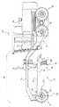
作業機械10の模範的な実施形態が図1に示されている。作業機械10は、モータグレーダ、バックホウローダ、農業用トラクタ、ホイールローダ、スキッドステアローダ、または公知の他の任意の種類の作業機械であり得る。作業機械10は、操舵可能な牽引装置12と、被駆動牽引装置14と、操舵可能な牽引装置12を被駆動牽引装置14に連結するフレーム16と、被駆動牽引装置14によって支持された動力源18と、動力源18から被駆動牽引装置14に動力を伝達するように構成された変速機(図示せず)とを含み得る。作業機械10はまた、例えば、牽引バー円形撥土板アセンブリ(DCM)20のような作業器具と、制御システム22とを含んでもよい。 An exemplary embodiment of
操舵可能な牽引装置12は、作業機械10のそれぞれの側面(1側面のみを図示)に配置された1つ以上の車輪24を含み得る。代わりに、操舵可能な牽引装置12は、履帯、ベルト、または他の牽引装置を含んでもよい。車輪24は、操舵中に使用するために鉛直軸線26を中心に回転可能である。車輪24は、加工面に係合するDCM20によって引き起こされる作用力に対抗するために、あるいはDCM20の高さを調整するために、水平軸線28を中心に傾き可能である。操舵可能な牽引装置12は駆動しても、しなくてもよい。 The
被駆動牽引装置14は、作業機械10のそれぞれの側面(1側面のみを図示)に配置された車輪30を含み得る。代わりに、被駆動牽引装置14は、履帯、ベルト、または他の牽引装置を含んでもよい。被駆動牽引装置14は、作業機械10のいずれかの側面に配置された車輪30の間の動力源18から動力を分割するように構成された差動歯車アセンブリ(図示せず)を含み得る。差動歯車アセンブリは、作業機械10の片側の車輪30が作業機械10の反対側に配置された車輪30よりも速く回転することを可能にする。差動歯車アセンブリはまた、以下により詳細に説明するロック特徴部を含んでもよい。被駆動牽引装置14は操舵可能でも、そうでなくてもよい。 The driven
フレーム16は、操舵可能な牽引装置12を被駆動牽引装置14に連結し得る。フレーム16は、被駆動牽引装置14をフレーム16に連結する関節型継手31を含み得る。作業機械10により、関節型継手31を介して、操舵可能な牽引装置12を被駆動牽引装置14に対し連結させることが可能である。作業機械10はまた、作動時に、被駆動牽引装置14に対して、操舵可能な牽引装置12の自動的な再位置合わせを行わせて、関節継手31が中立関節位置に戻るようにする中立関節特徴部を含んでもよい。
動力源18は、ディーゼルエンジン、ガソリンエンジン、天然ガスエンジンのようなエンジン、または公知の他の任意のエンジンでもよい。動力源18はまた、燃料電池、電力貯蔵装置のような他の動力源、あるいは公知の他の動力源でもよい。 The power source 18 may be a diesel engine, a gasoline engine, an engine such as a natural gas engine, or any other known engine. The power source 18 may also be other power sources such as fuel cells, power storage devices, or other known power sources.
変速機は、電気式変速機、油圧式変速機、機械式変速機、または公知の他の任意の変速機であり得る。変速機は、多数の出力速度比を生成するように動作可能であり、また出力速度の範囲で動力源18から被駆動牽引装置14に動力を移送するように構成し得る。 The transmission can be an electric transmission, a hydraulic transmission, a mechanical transmission, or any other known transmission. The transmission is operable to generate multiple output speed ratios and may be configured to transfer power from the power source 18 to the driven
DCM20は、油圧ラムアセンブリを介してフレーム16の中心部によって支持され、かつ玉継手33を介してフレーム16の前部部分に連結された牽引バーアセンブリ32を含むことが可能である。円形アセンブリ34は、追加の油圧ラムを介して牽引バーアセンブリ32に連結可能であり、またブレード38を有する撥土板アセンブリ36を支持するように構成し得る。DCM20は、フレーム16に対して鉛直にもまた水平にも位置付けることが可能である。DCM20はまた、牽引バーアセンブリ32に対して円形アセンブリ34と撥土板アセンブリ36を回転するように制御してもよい。ブレード38は、水平にもまた鉛直にも、かつ円形アセンブリ34に対し向けることが可能である。DCM20がなく、例えば、リッパ、バケットのような他の作業器具、または公知の他の作業器具で置き換え得ると考えられる。 The DCM 20 may include a
図2a、図3a、および図3bに示したように、制御システム22は、オペレータステーションのいずれかの側面にそれぞれ配置された左ジョイスティック制御器42と右ジョイスティック制御器44とを含むことが可能である。左右のジョイスティック制御器42と44は、DCM20の作業機械10および構成要素を位置付けおよび/または方向付けるように構成し得る。左右のジョイスティック制御器42、44はまた、作業機械10の様々な機能および/または特徴を作動するように使用してもよい。 As shown in FIGS. 2a, 3a, and 3b, the
図2aは、複数のボタン46、48、50、52、54と、レバー58に配置されたトリガ56とを有する左ジョイスティック制御器42を示している。作業機械10およびDCM20の様々な機能は、ボタン46、48、50、52、54の状態および/または位置、トリガ56の位置、およびレバー58の位置と向きに応じて、異なる方法で作動することが可能である。 FIG. 2 a shows a
例えば、ボタン46と48により、変速機出力速度比の変更を行うことが可能である。ボタン46により、より高い出力速度比に変速機をシフトさせることが可能である。ボタン48により、より低い出力速度比に変速機をシフトさせることが可能である。変速比シフトボタン46と48はレバー58内に収容してもよく、リッジ60がボタン46と48を互いに分離する。オペレータがボタン46または48の1つを押そうとするとき、リッジ60は、ボタン46または48の一方または他方に向かってオペレータの指を押圧する。リッジ60は、ボタン46と48の間の領域のオペレータの指の押し下げ運動を阻止することが可能である。このようにして、オペレータがうっかりして同時にボタン46とボタン48の両方を押圧することを防止し得る。 For example, it is possible to change the transmission output speed ratio with the
ボタン50と52は、車輪24が水平軸線28にわたって傾き面に対して傾斜するかまたは傾くようにさせ得る。ボタン50は、オペレータの視野に対して車輪24が左に傾くようにさせることが可能であり、一方、ボタン52は車輪24が右に傾くようにさせ得る。ボタン50と52によって引き起こされる車輪24の傾き速度は、個々のボタンの係合位置に対応し得る。例えば、ボタン50と52は、最大傾き速度に対応する最大位置と、最小傾き速度(例えば、ゼロの大きさの傾き速度)に対応する最小位置とを有する。ボタン50と52は、最大位置と最小位置との間の任意の位置に配置して、最大傾き速度と最小傾き速度との間の対応する速度で車輪24を傾けることが可能である。このようにして、ボタン50と52の運動は、ボタンによって制御される関連構成要素の移動速度に関係させ得る(すなわち、比例して)。ボタン50と52のいずれかを押し下げて車輪24の傾き速度を設定した後、車輪24は、ボタン50または52の位置が変更されるかあるいは車輪24の端部傾き位置に達するまで、同一の傾き速度で傾き続けることが可能である。
ボタン54は、関節操作の後に、関節型継手31を介して、操舵可能な牽引装置12を移動して戻して被駆動牽引装置14と位置合わせさせるように構成された中立関節ボタンであり得る。作動されると、この中立位置合わせの特徴は、オペレータが計測または視覚的観測に依存する必要なしに、操舵可能な装置12および被駆動牽引装置14の自動的な位置合わせを提供し得る。 The
作動時、トリガ56は、変速機状態を制御するように構成可能である。トリガ56は、変速機の前進、中立、および後進の出力方向の間で切り替わる3方向ロッカスイッチであり得る。トリガ56は、上方部分56aと、旋回点57を中心に旋回するように構成された下方部分56bを有し得る。中立状態の開始時、上方部分56aを第1の距離引っ張ることにより、逆の状態が選択可能であり、これによって、第1の出力回転方向の変速機の作動が引き起こされる。下方部分56bを第1の距離引っ張ることにより、変速機状態が中立に戻される。下方部分56bを第2の距離引っ張ることにより、前進状態が選択され、これによって、第1の方向と反対の第2の方向の変速機出力回転の回転が引き起こされる。上方部分56aを第2の距離引っ張ることにより、変速機状態が中立に戻される。 In operation, the
図2bの頂面図に示したように、長手方向軸線62を中心にレバー58をねじることにより、作業機械10の連結を引き起こすことが可能である。時計回り方向のレバー58のねじりは、操舵可能な牽引装置12を含む作業機械10の前方部分61が、(操舵可能な牽引装置14が連結される)フレーム16と被駆動牽引装置14とを接合する関節継手31を中心に時計回り方向に連結するようにさせることが可能である。同様に、反時計回り方向のレバー58のねじりは、前方部分61が、フレーム16と被駆動牽引装置14とを接合する関節継手31を中心に反時計回り方向に連結するようにさせることが可能である。 As shown in the top view of FIG. 2 b, twisting the
レバー58を軸線65を中心に前後に傾けることにより、ブレード38を移動させることが可能である。レバー58を軸線65を前方方向に傾けることにより、ブレード38の左端(オペレータの視野に対し)を下降させることが可能であり、一方、レバー58を軸線65を中心に後方方向に傾けることにより、ブレード38の左端を上昇させることが可能である。 The
軸線63に沿った前方/後方方向の軸線62からのレバー傾き角度の大きさは、ブレード運動の速度に関係させ得る。軸線65を中心とする長手方向軸線62からのレバー58の傾き角度が最大位置に近づくにつれ、関連方向のブレード38の移動速度は最大速度に近づく。このようにして、レバー58の運動は、ブレード38の移動速度に関係させ得る(例えば、比例して)。 The magnitude of the lever tilt angle from the forward /
軸線63を中心とする長手方向軸線62から左右にレバー58を傾けることにより、車輪24の角度を鉛直軸26を中心に回転させて、作業機械10を操舵することが可能である。軸線62を中心に左方向にレバー58を傾けることにより、オペレータの視野から観測されるように、車輪24を反時計回り方向に回転させることが可能である。同様に、軸線62を中心に右方向にレバー58を傾けることにより、車輪24を時計回り方向に回転させることが可能である。 By tilting the
左右方向の軸線65に沿った軸線62からのレバー傾き角度の大きさは、車輪24の回転に関係させ得る。軸線65に沿った長手方向軸線62からのレバー58の傾き角度が最大位置に近づくにつれ、関連方向の車輪24の回転角度は最大値に近づく。このようにして、レバー58の運動は、舵取り角に関係させ得る(すなわち、比例して)。 The magnitude of the lever tilt angle from the
レバー58は、オペレータの手の関節に対応するリッジを有するオペレータインタフェースを含むことが可能である。第1のリッジ64は、親指と手のひらとの間の関節に対応してもよく、一方、第2のリッジ66は、オペレータの手の指の関節に対応してもよい。リッジ64と66は、オペレータの手をレバー58に確実に配置することによって、オペレータの快適さを向上させることが可能である。 The
図3aと図3bは、制御システム22の右ジョイスティック制御器44を示している。右ジョイスティック制御器44は、4方向ロッカスイッチ70と、レバー80に配置されたトリガ78とを含み得る。作業機械10およびDCM20の様々な機能は、ロッカスイッチ70の係合位置、トリガ78の位置、およびレバー80の向きに応じて異なる方法で作動可能である。 FIGS. 3 a and 3 b show the
例えば、左右方向(オペレータの視野に対し)のロッカスイッチ70の作動により、左右方向からDCM20全体をシフトさせることが可能である。ロッカスイッチ70を左に揺動することにより、DCM20を左シフトさせることが可能である。ロッカスイッチ70を右に揺動することにより、DCM20を右シフトさせることが可能である。ロッカスイッチ70はまた、ブレード38を旋回軸線82を中心に回転させるかまたは傾けさせることが可能である。ロッカスイッチ70を前方に揺動することにより、ブレード38の頂部を加工面に向かって前方に傾けさせることが可能である。ロッカスイッチ70を後方に揺動することにより、ブレード38の頂部を後方に傾けさせ、ブレード38の底部を上方にかつ加工面から離れて移動させることが可能である。 For example, the
ロッカスイッチ70の移動によって引き起こされる旋回軸線82を中心とするDCM20の左右の移動および/またはブレード38の回転の速度は、個々の方向のロッカスイッチ70の係合位置と関係させ得る。ロッカスイッチ70は、左右方向のDCM20の最大シフト速度またはブレード38の最大回転速度に対応する最大揺動位置を有し得る。ロッカスイッチ70はまた、DCM20の最小シフト速度またはブレード38の最小回転速度に対応する最小揺動位置を有し得る。ロッカスイッチ70は、最大押し下げ位置と最小押し下げ位置との間の任意の位置に揺動して、関連方向の対応する最小および最大速度で、DCM20をシフトさせるかまたはブレード38を回転させることが可能である。このようにして、ロッカスイッチ70の運動は、ロッカスイッチ70によって制御される関連構成要素の移動速度に関係させ得る(すなわち、比例して)。左、右、前方、または後方の方向にロッカスイッチ70を揺動して、DCM20の移動速度またはブレード38の回転速度を設定した後、DCM20またはブレード38は、ロッカスイッチ70が新たな位置に揺動されるまで、同一の速度で移動または回転し続けることが可能である。さらに、ロッカスイッチ70を利用して、DCM20の移動およびブレード38の回転を同時に引き起こすことが可能である。特に、ロッカスイッチ70を前方/右方向、前方/左方向、後方/左方向、後方/右方向に向かって、あるいはそれらの間の任意の位置に揺動し、これによって、DCM20の同時の運動および関連方向のブレード38の回転を引き起こすことが可能である。 The speed of left and right movement of
ボタン76は、車輪30が作業機械10の他の側に配置された状態で、作業機械10の一方の側に配置された車輪30の速度をロックし、かつアンロックするために、ディファレンシャルロック特徴を作動しまた非作動にすることが可能である。作動されると、この特徴部は、被駆動牽引装置14の車輪30のそれぞれに実質的に均一または等しい速度を提供し、これによって、必要な場合に加工面に追加の牽引力を提供することが可能である。 The
トリガ78は、作動時にスロットル特徴部を制御するように構成可能である。作業機械10の運転中、動力源18の速度が、特定の機能を達成するために、所定の位置から制御可能に外れる場合がある。トリガ78を使用することにより、スロットルを所定の位置に戻るようにすることが可能である。例えば、オペレータが所望のスロットル位置を設定してもよい。例えば、方向転換、持ち上げ、アイドリングのような特定の機能、および公知の他の機能の間、これらの機能を適切に達成するためにオペレータによって設定された所望のスロットル位置から、スロットルが外れるようにすることが可能である。特定の機能の完了時、オペレータは、トリガ78を使用して、オペレータによって事前に設定された所望の位置にスロットルが戻るようにすることが可能である。 The
図3cの頂面図に示したように、長手方向軸線83を中心にレバー80をねじることにより、円形アセンブリ34を牽引バーアセンブリ32に対し回転させることが可能である。時計回り方向のレバー80のねじりは、オペレータの視野から観測されるように、円形アセンブリ34を時計回り方向に回転させることが可能である。同様に、時計回り方向のレバー80のねじりは、円形アセンブリ34を反時計回り方向に回転させることが可能である。 As shown in the top view of FIG. 3 c, the
軸線87を中心とする長手方向軸線83から左右にレバー80を傾けることにより、レバー80の傾きと同一方向にブレード38をシフトさせることが可能である。軸線87を中心とする左方向にレバー80を傾けることにより、オペレータの視野から観測されるように、ブレード38を左方向にシフトさせることが可能である。同様に、軸線87を中心とする右方向にレバー80を傾けることにより、オペレータの視野から観測されるように、ブレード38を右方向にシフトさせることが可能である。 It is possible to shift the
左右方向の軸線83からのレバー傾き角度の大きさは、同一方向のブレード38の移動速度に関係し得る。長手方向軸線83からのレバー80の傾き角度が軸線87を中心とする最大位置に近づくにつれ、関連方向のブレード38の移動速度は最大速度に近づく。 The magnitude of the lever tilt angle from the
軸線85を中心とする長手方向軸線83から前方/後方方向にレバー80を傾けることにより、オペレータの視野から観測されるように、ブレード38を鉛直方向に移動させることが可能である。レバー80を軸線85を中心に前方方向に傾けることにより、オペレータの視野から観測されるように、ブレード38の右端を作業面に向かって下降させることが可能である。同様に、レバー80を軸線85を中心に後方方向に傾けることにより、オペレータの視野から観測されるように、ブレード38の右端を作業面から上昇させることが可能である。 By tilting the
左右方向の軸線83からのレバー傾き角度の大きさは、ブレード38の右端の移動速度の大きさに関係し得る。長手方向軸線83からのレバー80の傾き角度が軸線85を中心とする最大位置に近づくにつれ、関連方向のブレード38の右端の移動速度は最大値に近づく。 The magnitude of the lever tilt angle from the
レバー58と同様に、レバー80は、オペレータの手の関節に対応するリッジを有するオペレータの手のインタフェースを含むことが可能である。第1のリッジ84は、親指と手のひらの間の関節に対応してもよく、一方、第2のリッジ86はオペレータの手の指の関節に対応してもよい。リッジ84と86は、オペレータの手をレバー58に確実に配置することによって、オペレータの快適性を向上させることが可能である。 Similar to lever 58,
レバー80はまた、ボタン76に近接したレバー80の一方の側に配置されたガード88を含み得る。ガード88は、うっかりしてまたは偶然にディファレンシャルロックボタン76を押すリスクを低減し得る。 The
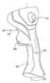
図4は、左および/または右のジョイスティック制御器42、44に使用するためのハンドスタビライザ92を示している。ハンドスタビライザ92は、基部96に連結されたリング94を含んでもよい。基部96は、個々のレバー58および/または80の一方の端部に配置し得る。リング94は、オペレータの手を支持するように構成可能である。ハンドスタビライザ92は、オペレータのアームレストまたは個々のジョイスティック制御器と単一ユニットとして組み合わせ可能であることが考えられる。リング以外の支持装置は、例えば、左および/または右のジョイスティック制御器42、44を実質的に囲む摩擦プレートのような基部96に連結し得ることがさらに考えられる。 FIG. 4 shows a
左および/または右のジョイスティック制御器42と44の操作中、オペレータはハンドスタビライザ92を使用して、左および/または右のジョイスティック制御器42と44の移動によって引き起こされる抵抗力を相殺することが可能である。オペレータは、個々のジョイスティック制御器の前方で、関連レバーの前方方向の傾きの間に後方方向に、リング94の部分に圧力を印加してもよい。同様に、関連のレバーを後方にまたは左右に傾けるとき、オペレータは、関連のレバーを傾きの方向に押すかまたは引っ張ることに起因する力に耐えるように、傾きの方向と反対にリング94に圧力を印加してもよい。 During operation of the left and / or
左右のジョイスティック制御器42、44を有する制御システム22は、作業機械または作業工具を位置付けるかおよび/または方向付けるために、あるいは作業機械の作動を制御するために、多数のオペレータ制御入力を必要とする任意の作業機械に適用可能である。制御システム22は、頻繁に使用されるアクチュエータを互いに非常に近接してかつ共通の制御器に設けることによって、オペレータの疲労を有効に低減することが可能である。頻繁に使用されるアクチュエータを共通の制御器に配置することにより、オペレータは、異なる制御器の間を移動することなしに異なる機械機能を制御することが可能である。 The
さらに、ボタン、トリガ、および/または制御システム22と関連したレバーの作動運動は、対応する作業機械または作業器具の運動と関係し得るので、これらの制御装置の操作は直感的である。制御装置の直感性は、作業機械10の品質および生産の改善、ならびに技能レベルの低いオペレータによる作業機械10の操作を可能にし得る。 Furthermore, the operation of these control devices is intuitive because the actuation movement of the levers associated with the buttons, triggers and / or
開示した実施形態の説明と実施を考慮することにより、他の実施形態が当業者には明白であろう。例えば、作業機械10の異なる多くの特徴および/または機能は、左右のジョイスティック制御器42と44によって制御することが可能である。左ジョイスティック制御器42によって制御されるものとして記述したそれらの機能および/または特徴は、代わりに、右ジョイスティック制御器44によって制御可能であり、その逆も可能である。左右のジョイスティック制御器42と44によって、追加のまたはより少ない特徴および/または機能を制御してもよい。特徴および/または機能は、例えば、スイッチ、プッシュ/プル装置、レバー、ディスクアジャスタ、および/または公知の他のオペレータ制御装置のような第1および第2のレバー58と80に配置された、ボタンおよびトリガ以外の様々なオペレータ制御装置によって制御可能である。さらに、ボタンまたはロッカスイッチによって制御されるものとして記述したそれらの機能および/または特徴はまた、レバー操作によって制御でき、その逆もできる。さらに、それらのボタン、ロッカスイッチ、トリガ、および/またはボタン、ロッカスイッチ、トリガ、および/またはレバーの位置に比例する関連構成要素の運動または速度を引き起こすものとして記述したレバーは、代わりに、オン/オフ型の制御装置であることが可能であり、この場合、影響を受ける構成要素の運動は連続的または段階的であり、一方、ボタン、トリガ、および/またはレバーは係合位置にある。説明および実施例は模範的なものに過ぎないと考えられ、本発明の真の範囲は、特許請求の範囲によって示されることが意図される。 Other embodiments will be apparent to those skilled in the art from consideration of the description and practice of the disclosed embodiments. For example, many different features and / or functions of
10 作業機械
12 操舵可能な牽引装置
14 被駆動牽引装置
16 フレーム
18 動力源
20 牽引バー円形撥土板アセンブリ(DCM)
22 制御システム
24 車輪
26 鉛直軸線
28 水平軸線
30 車輪
31 関節型継手
32 牽引バーアセンブリ
33 玉継手
34 円形アセンブリ
36 撥土板アセンブリ
38 ブレード
42 左ジョイスティック制御器
44 右ジョイスティック制御器
46 ボタン(変速機アップシフト)
48 ボタン(変速機ダウンシフト)
50 ボタン(車輪、左に傾斜)
52 ボタン(車輪、右に傾斜)
54 ボタン(中立関節)
56 トリガ(F−N−R)
56a 上方部分(トリガ)
56b 下方部分(トリガ)
57 旋回点
58 レバー
60 リッジ
61 前方部分
62 長手方向軸線
63 軸線
64 リッジ
65 軸線
66 リッジ
70 ロッカスイッチ(ブレードシフトおよび右端の前方/後方)
76 ボタン(ディファレンシャルロック)
78 トリガ(スロットル再開)
80 レバー
82 旋回軸線
83 長手方向軸線
84 リッジ
85 軸線
86 リッジ
87 軸線
88 ガード
92 ハンドスタビライザ
94 リング
96 基部
DESCRIPTION OF
22
48 buttons (transmission downshift)
50 buttons (wheel, tilt left)
52 button (wheel, tilt right)
54 buttons (neutral joint)
56 Trigger (FNR)
56a Upper part (trigger)
56b Lower part (trigger)
57
76 buttons (differential lock)
78 Trigger (restart throttle)
80
Claims (5)
Translated fromJapanese第1の長手方向軸線を有する第1のレバーであって、第1の長手方向軸線を中心とする第1のレバーのねじれ角が作業機械の関節速度と関係する第1のレバーと、
第1の長手方向軸線を有する第2のレバーであって、第2の長手方向軸線を中心とする第2のレバーのねじれ角が、少なくとも1つの回転軸線を中心とする作業器具の回転速度と関係する第2のレバーと、
第1および第2のレバーの複数のオペレータ制御装置とを備える制御システム。A control system for a work machine having an articulated joint and a work implement having at least one rotational axis,
A first lever having a first longitudinal axis, wherein the torsion angle of the first lever about the first longitudinal axis is related to the joint speed of the work machine;
A second lever having a first longitudinal axis, wherein the torsion angle of the second lever about the second longitudinal axis is the rotational speed of the work implement about the at least one rotational axis; A second lever involved;
A control system comprising a plurality of operator control devices for the first and second levers.
操舵可能な牽引装置と、
被駆動牽引装置と、
操舵可能な牽引装置を被駆動牽引装置に関節式に連結するための関節型継手を有するフレームと、
フレームおよび被駆動牽引装置の少なくとも1つによって支持された動力源と、
動力源に動作的に連結されかつ動力源から被駆動牽引装置に動力を伝達するように構成された変速機であって、ある範囲の出力速度比を有する変速機と、
フレームに動作的に連結されかつ少なくとも1つの回転軸線を有する作業器具と、
制御システムとを備え、制御システムが、
第1の長手方向軸線を有する第1のレバーであって、第1の長手方向軸線を中心とする第1のレバーのねじれ角が作業機械の関節速度と関係する第1のレバーと、
第2の長手方向軸線を有する第2のレバーであって、
第2の長手方向軸線を中心とする第2のレバーのねじれ角が、少なくとも1つの軸線を中心とする作業器具の回転速度と関係し、第1のレバーおよび第2のレバーの少なくとも1つが、少なくとも1つの傾き軸線を中心に傾くように構成され、
作業機械の操舵方向が、少なくとも1つの傾き軸線を中心とする第1のレバーおよび第2のレバーの少なくとも1つの傾き角度と関係する第2のレバーと、
第1および第2のレバーに配置された複数のオペレータ制御装置であって、
作業機械が、傾き面に対して傾くように構成された操舵可能な牽引装置を含み、傾き面に対して操舵可能な牽引装置の傾き速度が、複数のオペレータ制御装置の少なくとも1つの係合位置に関係し、
変速機の出力速度比が、複数のオペレータ制御装置の少なくとも1つによって選択可能であり、
複数のオペレータ制御装置の少なくとも1つが、関節型継手を中立関節位置に配置するように構成され、
作業機械が、複数の被駆動牽引装置と、複数の被駆動牽引装置が互いに対して異なる速度で回転することを可能にする差動歯車機構とを含み、また複数のオペレータ制御装置の少なくとも1つが、差動歯車機構を選択的にロックするように、かつ実質的に均一な速度で複数の被駆動牽引装置を回転させるように構成され、
複数のオペレータ制御装置の1つが作業機械のスロットル特徴部に係合するように構成される複数のオペレータ制御装置と、
第1の作業器具運動を引き起こすように第1の方向の運動のために、また第2の作業器具運動を引き起こすように第1の方向に直角の第2の方向の運動のために構成された少なくとも1つの4方向制御装置と、を含む作業機械。A working machine,
A steerable traction device;
A driven traction device;
A frame having an articulated joint for articulating a steerable traction device to a driven traction device;
A power source supported by at least one of a frame and a driven traction device;
A transmission operatively coupled to a power source and configured to transmit power from the power source to a driven traction device, the transmission having a range of output speed ratios;
A work implement operably coupled to the frame and having at least one axis of rotation;
A control system, the control system comprising:
A first lever having a first longitudinal axis, wherein the torsion angle of the first lever about the first longitudinal axis is related to the joint speed of the work machine;
A second lever having a second longitudinal axis,
A twist angle of the second lever about the second longitudinal axis is related to a rotational speed of the work implement about the at least one axis, and at least one of the first lever and the second lever is Configured to tilt about at least one tilt axis;
A second lever in which the steering direction of the work machine is related to at least one tilt angle of the first lever and the second lever about at least one tilt axis;
A plurality of operator control devices disposed on the first and second levers,
The work machine includes a steerable traction device configured to be inclined with respect to an inclined surface, and the inclination speed of the traction device steerable with respect to the inclined surface is at least one engagement position of the plurality of operator control devices. Related to
The output speed ratio of the transmission can be selected by at least one of a plurality of operator control devices;
At least one of the plurality of operator controls is configured to place the articulated joint at a neutral joint position;
The work machine includes a plurality of driven traction devices and a differential gear mechanism that allows the plurality of driven traction devices to rotate at different speeds relative to each other, and at least one of the plurality of operator control devices is Configured to selectively lock the differential gear mechanism and to rotate the plurality of driven traction devices at a substantially uniform speed;
A plurality of operator controls, wherein one of the plurality of operator controls is configured to engage a throttle feature of the work machine;
Configured for movement in a first direction to cause a first work implement movement, and for movement in a second direction perpendicular to the first direction to cause a second work implement movement. A work machine including at least one four-way control device.
作業機械の部分が、時計回りおよび反時計回り方向の一方にかつ第1のねじれ角に関係する関節速度で関節型継手を中心に回転するように、第1のねじれ角にわたって時計回りおよび反時計回りの方向の一方に第1のレバーをねじって、作業機械の関節型継手の連結を引き起こすステップと、
第2のねじれ角にわたって時計回りおよび反時計回りの方向の一方に第2のレバーをねじって、時計回りおよび反時計回り方向の同一の一方にかつ第2のねじれ角に関係する回転速度で、第1の軸線を中心とする作業機械の回転を引き起こすステップを含む方法であって、
複数のオペレータ制御装置が第1および第2のレバーに配置される、方法。
A method for controlling a work machine,
Clockwise and counterclockwise over the first twist angle so that the portion of the work machine rotates about the articulated joint in one of the clockwise and counterclockwise directions and at a joint speed related to the first twist angle. Twisting the first lever in one of the circumferential directions to cause the connection of the articulated joint of the work machine;
Twist the second lever in one of the clockwise and counterclockwise directions over the second twist angle, at the rotational speed related to the same one in the clockwise and counterclockwise directions and the second twist angle, Causing a rotation of the work machine about a first axis comprising the steps of:
A method wherein a plurality of operator controls are disposed on the first and second levers.
Applications Claiming Priority (1)
| Application Number | Priority Date | Filing Date | Title |
|---|---|---|---|
| US10/872,431US7497298B2 (en) | 2004-06-22 | 2004-06-22 | Machine joystick control system |
Publications (1)
| Publication Number | Publication Date |
|---|---|
| JP2006052632Atrue JP2006052632A (en) | 2006-02-23 |
Family
ID=35479423
Family Applications (1)
| Application Number | Title | Priority Date | Filing Date |
|---|---|---|---|
| JP2005181919APendingJP2006052632A (en) | 2004-06-22 | 2005-06-22 | Work machine joystick control system |
Country Status (3)
| Country | Link |
|---|---|
| US (1) | US7497298B2 (en) |
| JP (1) | JP2006052632A (en) |
| CA (1) | CA2506301C (en) |
Cited By (2)
| Publication number | Priority date | Publication date | Assignee | Title |
|---|---|---|---|---|
| WO2012124767A1 (en)* | 2011-03-15 | 2012-09-20 | 日立建機株式会社 | Wheel rotor |
| JP2017033282A (en)* | 2015-07-31 | 2017-02-09 | 株式会社クボタ | Operating device |
Families Citing this family (71)
| Publication number | Priority date | Publication date | Assignee | Title |
|---|---|---|---|---|
| US7334658B2 (en)* | 2004-12-23 | 2008-02-26 | Caterpillar Inc. | Steering system with joystick mounted controls |
| DE102007005253A1 (en)* | 2007-02-02 | 2008-08-07 | Deere & Company, Moline | Operating device for a vehicle |
| US20090198414A1 (en)* | 2008-01-31 | 2009-08-06 | Caterpillar Inc. | Operator interface for controlling a vehicle |
| US20090200116A1 (en)* | 2008-02-12 | 2009-08-13 | Wiggins Michael M | Multi-function joystick for forklift control |
| US8091678B2 (en)* | 2008-03-07 | 2012-01-10 | Deere & Company | Input control pattern |
| US7798278B2 (en)* | 2008-03-12 | 2010-09-21 | Tesinsky Vincent E | Remote control for shifting the gears of a snowplow truck transmission |
| JP5235005B2 (en)* | 2009-08-31 | 2013-07-10 | 株式会社クボタ | grip |
| USD645046S1 (en) | 2009-09-03 | 2011-09-13 | Bucyrus International, Inc. | Joystick with indents |
| USD640258S1 (en) | 2009-09-03 | 2011-06-21 | Bucyrus International, Inc. | Joystick |
| US8100218B2 (en)* | 2009-10-19 | 2012-01-24 | Cnh America Llc | Electronic throttle on control handle |
| US8272468B2 (en)* | 2010-02-25 | 2012-09-25 | Yanmar Co., Ltd. | Work machine |
| US8380402B2 (en) | 2010-09-14 | 2013-02-19 | Bucyrus Intl. Inc. | Control systems and methods for heavy equipment |
| US8412420B2 (en) | 2010-12-14 | 2013-04-02 | Deere & Company | Wheel lean control |
| US20130133469A1 (en)* | 2011-11-28 | 2013-05-30 | Embraer S.A. | Sidestick controller grip |
| US20130160737A1 (en)* | 2011-12-21 | 2013-06-27 | Cnh America Llc | Electronic throttle on control handle |
| FI20125660A7 (en)* | 2012-06-14 | 2013-12-15 | John Deere Forestry Oy | Control switch to be used in a working machine |
| WO2014077849A1 (en)* | 2012-11-19 | 2014-05-22 | Flowserve Management Company | Control systems for valve actuators, valve actuators and related methods |
| US9055719B2 (en)* | 2012-12-06 | 2015-06-16 | Deere & Company | Method and apparatus for ride control activation |
| US8979208B2 (en)* | 2013-01-08 | 2015-03-17 | Caterpillar Inc. | Transmission and hoist control arrangement |
| US8905183B2 (en)* | 2013-03-14 | 2014-12-09 | The Raymond Corporation | Contoured backrest with integrated control module for use with a material handling vehicle |
| USD736719S1 (en)* | 2013-07-24 | 2015-08-18 | J. Schmalz Gmbh | Control element |
| CN103485384B (en)* | 2013-09-25 | 2015-09-16 | 于进策 | Excavator single handle control method and system |
| US20150101440A1 (en)* | 2013-10-11 | 2015-04-16 | Deere & Company | Multifunctional control for a work vehicle |
| USD725681S1 (en) | 2013-10-11 | 2015-03-31 | Deere & Company | Control grip |
| US9342091B2 (en) | 2014-03-04 | 2016-05-17 | Deere & Company | Multi-function control grip for work vehicles |
| USD735100S1 (en) | 2014-04-21 | 2015-07-28 | Caterpillar Inc. | Transmission shifter |
| US9086130B1 (en)* | 2014-04-21 | 2015-07-21 | Caterpillar Inc. | Transmission and hoist control arrangement |
| US9908614B2 (en)* | 2014-05-02 | 2018-03-06 | Sikorsky Aircraft Corporation | Crew seat integral inceptor system for aircraft |
| DE102014208349B4 (en)* | 2014-05-05 | 2024-06-13 | Volkswagen Aktiengesellschaft | Motor vehicle with a device for at least partially controlling the longitudinal and/or transverse dynamics of the motor vehicle by hand |
| DE102014208350B4 (en)* | 2014-05-05 | 2024-06-06 | Volkswagen Aktiengesellschaft | Motor vehicle with a device for at least partially controlling the longitudinal and/or transverse dynamics of the motor vehicle by hand |
| JP1516612S (en)* | 2014-07-03 | 2015-02-02 | ||
| USD747721S1 (en)* | 2014-09-19 | 2016-01-19 | Caterpillar Inc. | Controller |
| JP1528194S (en)* | 2014-10-15 | 2015-07-06 | ||
| USD753118S1 (en)* | 2014-11-24 | 2016-04-05 | Caterpillar Inc. | Controller |
| US10036139B2 (en)* | 2014-11-24 | 2018-07-31 | Caterpillar Inc. | Machine input device having multi-axis tool control |
| AU2016211569C1 (en) | 2015-01-29 | 2019-01-17 | Crown Equipment Corporation | Control module and palm rest for a materials handling vehicle |
| USD775449S1 (en) | 2015-02-06 | 2016-12-27 | Crown Equipment Corporation | Vehicle handhold element |
| USD767457S1 (en) | 2015-02-06 | 2016-09-27 | Crown Equipment Corporation | Vehicle palm rest |
| DE202015103509U1 (en)* | 2015-07-03 | 2015-07-21 | MULAG FAHRZEUGWERK Heinz Wössner GmbH & Co. KG | control |
| JP1543259S (en)* | 2015-07-31 | 2016-02-08 | ||
| JP1543258S (en)* | 2015-07-31 | 2016-02-08 | ||
| US9777460B2 (en)* | 2015-10-22 | 2017-10-03 | Deere & Company | Operator control for work vehicles |
| US9797114B2 (en) | 2015-10-22 | 2017-10-24 | Deere & Company | Work vehicle operator control with increment adjust |
| US9771705B2 (en) | 2015-10-22 | 2017-09-26 | Deere & Company | Work vehicle operator control |
| US9777461B2 (en) | 2015-10-22 | 2017-10-03 | Deere & Company | Distributed operator control for work vehicles |
| US10415213B2 (en)* | 2015-10-28 | 2019-09-17 | Cooper Gray Robotics, Llc | Remotely controlled construction equipment |
| JP1549306S (en)* | 2015-11-04 | 2016-05-16 | ||
| JP6487822B2 (en)* | 2015-11-05 | 2019-03-20 | ヤンマー株式会社 | Tractor |
| CA2949506C (en) | 2015-11-25 | 2024-01-02 | Johnnie Leroy Mason | Joystick controlled scraper blade assembly |
| US10000909B2 (en)* | 2015-12-21 | 2018-06-19 | Altec Industries, Inc. | Control device for hydraulic equipment |
| WO2017141420A1 (en)* | 2016-02-19 | 2017-08-24 | 株式会社小松製作所 | Operating device for work vehicle |
| US9840826B2 (en) | 2016-03-22 | 2017-12-12 | Deere & Company | Interchangeable interface system for work vehicle |
| US10301009B2 (en)* | 2016-08-26 | 2019-05-28 | Kitty Hawk Corporation | Aircraft hand controller with decoupled throttle |
| GB201617661D0 (en)* | 2016-10-19 | 2016-11-30 | Agco International Gmbh | A control lever for a vehicle |
| JP2018118684A (en)* | 2017-01-27 | 2018-08-02 | 本田技研工業株式会社 | Steering device for vehicle |
| USD872665S1 (en)* | 2017-02-28 | 2020-01-14 | Cnh Industrial America Llc | Set of control grips for a construction machine |
| USD844514S1 (en)* | 2017-07-26 | 2019-04-02 | Deere & Company | Multi-functional joystick for an agricultural vehicle |
| EP3508944B1 (en)* | 2017-11-24 | 2025-07-16 | Komatsu Ltd. | Operating lever and work vehicle |
| US20200012309A1 (en)* | 2018-07-09 | 2020-01-09 | Deere & Company | Universal work vehicle control grip |
| US10591948B1 (en) | 2018-08-30 | 2020-03-17 | Essex Industries, Inc. | Collective control system for a rotorcraft |
| US11353111B2 (en)* | 2019-02-11 | 2022-06-07 | Caterpillar Paving Products Inc. | Traction control method for a rotary mixer |
| US20200256035A1 (en)* | 2019-02-13 | 2020-08-13 | Caterpillar Inc. | Configurable control input for work machine |
| US11396736B2 (en) | 2019-03-11 | 2022-07-26 | Caterpillar Inc. | Control system for a work machine |
| CN110126912A (en)* | 2019-05-13 | 2019-08-16 | 成都凯天电子股份有限公司 | Automatic centering steering system for controlling the centering maintenance work platform |
| JP7188298B2 (en) | 2019-07-02 | 2022-12-13 | 株式会社豊田自動織機 | Operation lever device for industrial vehicles |
| DE102020000729A1 (en)* | 2020-02-04 | 2021-08-05 | Man Truck & Bus Se | Arrangement of a palm rest and a control element for a vehicle |
| US11614766B2 (en) | 2020-04-09 | 2023-03-28 | Caterpillar Inc. | Machine joystick with comfort and accessibility features |
| US11573591B2 (en) | 2020-04-10 | 2023-02-07 | Caterpillar Inc. | Machine joystick with ergonomic features |
| US11866909B2 (en)* | 2020-11-04 | 2024-01-09 | Caterpillar Inc. | Machine control component with input device to control machine display |
| JP7629330B2 (en)* | 2021-03-31 | 2025-02-13 | 株式会社小松製作所 | Control device, operation device, control method, and work vehicle |
| USD1038132S1 (en)* | 2024-04-16 | 2024-08-06 | Jiecheng ZHANG | Toy remote control |
Citations (3)
| Publication number | Priority date | Publication date | Assignee | Title |
|---|---|---|---|---|
| JPH07158118A (en)* | 1993-12-09 | 1995-06-20 | Tokyo Riyuuki Seizo Kk | Travel controller of crawler drill |
| JPH11181815A (en)* | 1997-12-19 | 1999-07-06 | Hitachi Constr Mach Co Ltd | Working machine |
| US6140787A (en)* | 1997-07-23 | 2000-10-31 | Rsi Technologies Ltd. | Method and apparatus for controlling a work implement |
Family Cites Families (49)
| Publication number | Priority date | Publication date | Assignee | Title |
|---|---|---|---|---|
| US3580636A (en) | 1970-01-14 | 1971-05-25 | Us Air Force | Dual side arm controller |
| US4055230A (en) | 1974-01-11 | 1977-10-25 | International Harvester Company | Vehicle control armrest in a vibration isolated control module |
| DE2718579C3 (en) | 1977-04-26 | 1981-04-02 | Steinbock Gmbh, 8052 Moosburg | Armrests for driver's seats, in particular for work machines, for example forklifts |
| US4140200A (en) | 1977-05-27 | 1979-02-20 | J. I. Case Company | Control device and arm support |
| US4392546A (en) | 1980-12-24 | 1983-07-12 | Deere & Company | Suspended operator station |
| NL8200614A (en) | 1982-02-17 | 1983-09-16 | Rotterdamsche Droogdok Mij | COMMERCIAL VEHICLE. |
| US4476954A (en) | 1982-09-22 | 1984-10-16 | Johnson Engineering Corporation | Remote control for motor vehicle |
| JPH0671891B2 (en) | 1983-06-24 | 1994-09-14 | 株式会社小松製作所 | Tracked tractor controller |
| US4702520A (en) | 1984-10-12 | 1987-10-27 | Deere & Company | Adjustable armrest with integral vehicle controls |
| DE3728373C2 (en) | 1987-08-26 | 1994-01-27 | Porsche Ag | Manually operated control device for control valves |
| USD323279S (en) | 1987-08-26 | 1992-01-21 | Dr. Ing. H.C.F. Porsche Aktiengesellschaft | Rear, top, bottom, left and right surfaces of an armrest control lever for use with a motor vehicle transmission or the like |
| US4914976A (en) | 1988-04-13 | 1990-04-10 | Honeywell Inc. | Five and six degree of freedom hand controllers |
| US4895039A (en) | 1988-07-20 | 1990-01-23 | Honeywell Inc. | Hand controller having pivot axis for minimizing forearm movement |
| EP0484402B1 (en)* | 1989-07-24 | 1996-06-05 | The Dow Chemical Company | Ignition resistant polycarbonate blends |
| US5042314A (en) | 1989-11-02 | 1991-08-27 | Caterpillar Inc. | Steering and transmission shifting control mechanism |
| US5086870A (en) | 1990-10-31 | 1992-02-11 | Division Driving Systems, Inc. | Joystick-operated driving system |
| IT223321Z2 (en) | 1991-10-15 | 1995-06-21 | Fiat Auto Spa | ARMREST FOR A VEHICLE. |
| CA2062147C (en) | 1992-03-02 | 1995-07-25 | Kenji Hara | Multi-axial joy stick device |
| US5584346A (en) | 1992-07-27 | 1996-12-17 | Komatsu Est Corp. | Control system for a motor grader |
| US5244066A (en) | 1992-10-16 | 1993-09-14 | Caterpillar Inc. | Vehicle control console having finger tip controls |
| GB2276360B (en) | 1993-03-22 | 1996-07-24 | Crown Gabelstapler Gmbh | Electric forklift trucks |
| US5448028A (en) | 1993-12-10 | 1995-09-05 | Davidson Textron, Inc. | Armrest electrical switch arrangement with soft interior trim panel |
| IT232519Y1 (en) | 1994-08-03 | 2000-01-10 | Borio Valerio | COMMAND GROUP FOR THE CONDUCT OF AN AGRICULTURAL TRACTOR |
| FR2743232B1 (en)* | 1995-12-29 | 1998-01-30 | Thomson Multimedia Sa | WIRELESS TRANSMISSION METHOD AND DEVICE |
| DE19624463A1 (en) | 1996-06-19 | 1998-01-02 | Fendt Xaver Gmbh & Co | Control device for commercial vehicles, in particular for agricultural tractors |
| US5924515A (en) | 1997-03-17 | 1999-07-20 | New Holland North America, Inc. | Operator seat sliding control console |
| USD429246S (en) | 1997-04-09 | 2000-08-08 | Timberjack Oy | Arm support with control panel |
| DE19717622A1 (en) | 1997-04-25 | 1998-10-29 | Linde Ag | Driver's seat holding device for lift truck |
| US6065365A (en) | 1997-05-08 | 2000-05-23 | Case Corporation | Control lever assembly |
| US6061617A (en) | 1997-10-21 | 2000-05-09 | Case Corporation | Adaptable controller for work vehicle attachments |
| US6039141A (en) | 1998-02-23 | 2000-03-21 | Case Corporation | Moving operator and display unit |
| US6164285A (en) | 1998-03-16 | 2000-12-26 | Case Corporation | Position-adjustable control console |
| USH1840H (en) | 1998-09-23 | 2000-02-01 | Caterpillar Inc. | Apparatus and method of providing calibration information to an operator of a work machine |
| USD427207S (en) | 1998-11-13 | 2000-06-27 | Komatsu America International Company | Right hand armrest |
| USH1851H (en) | 1998-12-18 | 2000-06-06 | Caterpillar Inc. | Motor grader having dual steering mechanisms |
| USH1831H (en) | 1998-12-18 | 2000-02-01 | Caterpillar Inc. | Ergonomic motor grader vehicle control apparatus |
| US6152239A (en) | 1999-01-25 | 2000-11-28 | Caterpillar Inc. | Ergonomic electronic hand control for a motor grader |
| JP3348774B2 (en) | 1999-03-24 | 2002-11-20 | 株式会社小松製作所 | Position adjustment device for work vehicle control console |
| US6536825B2 (en) | 2000-05-09 | 2003-03-25 | Lear Corporation | Control panel for a vehicle |
| CA2327038C (en) | 2000-11-22 | 2008-04-22 | Champion Road Machinery Limited | Motor grader vehicle control arrangement |
| US6550562B2 (en) | 2000-12-08 | 2003-04-22 | Clark Equipment Company | Hand grip with microprocessor for controlling a power machine |
| US6948582B2 (en) | 2001-03-02 | 2005-09-27 | Toyota Jidosha Kabushiki Kaisha | Shift device for vehicle |
| USD463459S1 (en) | 2001-04-19 | 2002-09-24 | Komatsu Ltd. | Operator's seat for construction machinery |
| CA2345951A1 (en) | 2001-05-04 | 2002-11-04 | Volvo Motor Graders Limited | Advanced motor grader controls |
| US6634453B2 (en) | 2001-08-29 | 2003-10-21 | Deere & Company | Ergonomic tractor seat armrest and hand control |
| US6843681B2 (en) | 2001-12-06 | 2005-01-18 | The Boeing Company | Replacement cover having integrated data ports for power port assembly on commercial aircraft |
| JP2003292298A (en) | 2002-04-03 | 2003-10-15 | Toyota Industries Corp | Industrial vehicle |
| JP4291544B2 (en) | 2002-04-03 | 2009-07-08 | 株式会社豊田自動織機 | Industrial vehicle |
| US7178623B2 (en) | 2003-12-19 | 2007-02-20 | Caterpillar Inc | Operator control assembly |
- 2004
- 2004-06-22USUS10/872,431patent/US7497298B2/enactiveActive
- 2005
- 2005-05-03CACA2506301Apatent/CA2506301C/ennot_activeExpired - Fee Related
- 2005-06-22JPJP2005181919Apatent/JP2006052632A/enactivePending
Patent Citations (3)
| Publication number | Priority date | Publication date | Assignee | Title |
|---|---|---|---|---|
| JPH07158118A (en)* | 1993-12-09 | 1995-06-20 | Tokyo Riyuuki Seizo Kk | Travel controller of crawler drill |
| US6140787A (en)* | 1997-07-23 | 2000-10-31 | Rsi Technologies Ltd. | Method and apparatus for controlling a work implement |
| JPH11181815A (en)* | 1997-12-19 | 1999-07-06 | Hitachi Constr Mach Co Ltd | Working machine |
Cited By (3)
| Publication number | Priority date | Publication date | Assignee | Title |
|---|---|---|---|---|
| WO2012124767A1 (en)* | 2011-03-15 | 2012-09-20 | 日立建機株式会社 | Wheel rotor |
| JP5814258B2 (en)* | 2011-03-15 | 2015-11-17 | 日立建機株式会社 | Wheel loader |
| JP2017033282A (en)* | 2015-07-31 | 2017-02-09 | 株式会社クボタ | Operating device |
Also Published As
| Publication number | Publication date |
|---|---|
| CA2506301C (en) | 2012-10-09 |
| CA2506301A1 (en) | 2005-12-22 |
| US7497298B2 (en) | 2009-03-03 |
| US20050279561A1 (en) | 2005-12-22 |
Similar Documents
| Publication | Publication Date | Title |
|---|---|---|
| JP2006052632A (en) | Work machine joystick control system | |
| EP2311710B1 (en) | Electronic throttle on control handle | |
| CN103046608B (en) | The control control frame of Work machine | |
| USH1831H (en) | Ergonomic motor grader vehicle control apparatus | |
| US8380402B2 (en) | Control systems and methods for heavy equipment | |
| US6152239A (en) | Ergonomic electronic hand control for a motor grader | |
| US20020166267A1 (en) | Advanced motor grader controls | |
| US10302027B2 (en) | Variable engine speed control | |
| US11573591B2 (en) | Machine joystick with ergonomic features | |
| US20160032564A1 (en) | Multiple Control Patterns for Machines with Hand and Foot Controls | |
| US20130173117A1 (en) | Electronic tag along | |
| US20080023250A1 (en) | Ergonomic machine control console | |
| CN111677042B (en) | Control system for work machine | |
| US20050065689A1 (en) | Work implement control system and method | |
| US20130173138A1 (en) | Dual throttle engine speed control | |
| US20220234645A1 (en) | Vehicle steering assembly | |
| US9181676B2 (en) | Machine foot control operational pattern and method thereof | |
| US20130160737A1 (en) | Electronic throttle on control handle | |
| US5992260A (en) | Operating device for a working vehicle | |
| US11614766B2 (en) | Machine joystick with comfort and accessibility features | |
| JPH11202961A (en) | Operating device and operating method of work vehicle | |
| AU2024216382A1 (en) | Vehicle steering assembly | |
| JPH08188059A (en) | Transmission of earthwork vehicle | |
| JPH0673759A (en) | Changeover device for control lever |
Legal Events
| Date | Code | Title | Description |
|---|---|---|---|
| A621 | Written request for application examination | Free format text:JAPANESE INTERMEDIATE CODE: A621 Effective date:20080616 | |
| A977 | Report on retrieval | Free format text:JAPANESE INTERMEDIATE CODE: A971007 Effective date:20100118 | |
| A131 | Notification of reasons for refusal | Free format text:JAPANESE INTERMEDIATE CODE: A131 Effective date:20100423 | |
| A02 | Decision of refusal | Free format text:JAPANESE INTERMEDIATE CODE: A02 Effective date:20101001 |