JP2006048302A - Piezoelectric composite device, manufacturing method thereof, handling method thereof, control method thereof, input / output device and electronic apparatus - Google Patents
Piezoelectric composite device, manufacturing method thereof, handling method thereof, control method thereof, input / output device and electronic apparatusDownload PDFInfo
- Publication number
- JP2006048302A JP2006048302AJP2004227053AJP2004227053AJP2006048302AJP 2006048302 AJP2006048302 AJP 2006048302AJP 2004227053 AJP2004227053 AJP 2004227053AJP 2004227053 AJP2004227053 AJP 2004227053AJP 2006048302 AJP2006048302 AJP 2006048302A
- Authority
- JP
- Japan
- Prior art keywords
- electrode
- piezoelectric
- force
- actuator
- input
- Prior art date
- Legal status (The legal status is an assumption and is not a legal conclusion. Google has not performed a legal analysis and makes no representation as to the accuracy of the status listed.)
- Pending
Links
Images


Classifications
- G—PHYSICS
- G06—COMPUTING OR CALCULATING; COUNTING
- G06F—ELECTRIC DIGITAL DATA PROCESSING
- G06F3/00—Input arrangements for transferring data to be processed into a form capable of being handled by the computer; Output arrangements for transferring data from processing unit to output unit, e.g. interface arrangements
- G06F3/01—Input arrangements or combined input and output arrangements for interaction between user and computer
- G06F3/016—Input arrangements with force or tactile feedback as computer generated output to the user
- G—PHYSICS
- G06—COMPUTING OR CALCULATING; COUNTING
- G06F—ELECTRIC DIGITAL DATA PROCESSING
- G06F3/00—Input arrangements for transferring data to be processed into a form capable of being handled by the computer; Output arrangements for transferring data from processing unit to output unit, e.g. interface arrangements
- G06F3/01—Input arrangements or combined input and output arrangements for interaction between user and computer
- G06F3/011—Arrangements for interaction with the human body, e.g. for user immersion in virtual reality
- H—ELECTRICITY
- H03—ELECTRONIC CIRCUITRY
- H03K—PULSE TECHNIQUE
- H03K17/00—Electronic switching or gating, i.e. not by contact-making and –breaking
- H03K17/94—Electronic switching or gating, i.e. not by contact-making and –breaking characterised by the way in which the control signals are generated
- H03K17/96—Touch switches
- H03K17/964—Piezoelectric touch switches
- H03K17/9643—Piezoelectric touch switches using a plurality of detectors, e.g. keyboard
- H—ELECTRICITY
- H10—SEMICONDUCTOR DEVICES; ELECTRIC SOLID-STATE DEVICES NOT OTHERWISE PROVIDED FOR
- H10N—ELECTRIC SOLID-STATE DEVICES NOT OTHERWISE PROVIDED FOR
- H10N30/00—Piezoelectric or electrostrictive devices
- H10N30/01—Manufacture or treatment
- H10N30/05—Manufacture of multilayered piezoelectric or electrostrictive devices, or parts thereof, e.g. by stacking piezoelectric bodies and electrodes
- H10N30/053—Manufacture of multilayered piezoelectric or electrostrictive devices, or parts thereof, e.g. by stacking piezoelectric bodies and electrodes by integrally sintering piezoelectric or electrostrictive bodies and electrodes
- H—ELECTRICITY
- H10—SEMICONDUCTOR DEVICES; ELECTRIC SOLID-STATE DEVICES NOT OTHERWISE PROVIDED FOR
- H10N—ELECTRIC SOLID-STATE DEVICES NOT OTHERWISE PROVIDED FOR
- H10N30/00—Piezoelectric or electrostrictive devices
- H10N30/101—Piezoelectric or electrostrictive devices with electrical and mechanical input and output, e.g. having combined actuator and sensor parts
- H—ELECTRICITY
- H10—SEMICONDUCTOR DEVICES; ELECTRIC SOLID-STATE DEVICES NOT OTHERWISE PROVIDED FOR
- H10N—ELECTRIC SOLID-STATE DEVICES NOT OTHERWISE PROVIDED FOR
- H10N30/00—Piezoelectric or electrostrictive devices
- H10N30/50—Piezoelectric or electrostrictive devices having a stacked or multilayer structure
- H—ELECTRICITY
- H10—SEMICONDUCTOR DEVICES; ELECTRIC SOLID-STATE DEVICES NOT OTHERWISE PROVIDED FOR
- H10N—ELECTRIC SOLID-STATE DEVICES NOT OTHERWISE PROVIDED FOR
- H10N30/00—Piezoelectric or electrostrictive devices
- H10N30/80—Constructional details
- H10N30/87—Electrodes or interconnections, e.g. leads or terminals
- H10N30/872—Interconnections, e.g. connection electrodes of multilayer piezoelectric or electrostrictive devices
- H10N30/874—Interconnections, e.g. connection electrodes of multilayer piezoelectric or electrostrictive devices embedded within piezoelectric or electrostrictive material, e.g. via connections
- G—PHYSICS
- G06—COMPUTING OR CALCULATING; COUNTING
- G06F—ELECTRIC DIGITAL DATA PROCESSING
- G06F2203/00—Indexing scheme relating to G06F3/00 - G06F3/048
- G06F2203/041—Indexing scheme relating to G06F3/041 - G06F3/045
- G06F2203/04105—Pressure sensors for measuring the pressure or force exerted on the touch surface without providing the touch position
Landscapes
- Engineering & Computer Science (AREA)
- General Engineering & Computer Science (AREA)
- Theoretical Computer Science (AREA)
- Human Computer Interaction (AREA)
- Physics & Mathematics (AREA)
- General Physics & Mathematics (AREA)
- Manufacturing & Machinery (AREA)
- General Electrical Machinery Utilizing Piezoelectricity, Electrostriction Or Magnetostriction (AREA)
- User Interface Of Digital Computer (AREA)
- Position Input By Displaying (AREA)
- Switch Cases, Indication, And Locking (AREA)
- Push-Button Switches (AREA)
Abstract
Translated fromJapaneseDescription
Translated fromJapanese本発明は、触覚入力機能付きの携帯電話機や、デジタルカメラ、携帯端末装置、リモートコントローラ等に適用して好適な圧電複合装置、その製造方法、その取扱方法、その制御方法、入出力装置及び電子機器に関する。 The present invention relates to a piezoelectric composite device suitable for application to a mobile phone with a tactile input function, a digital camera, a portable terminal device, a remote controller, etc., a manufacturing method thereof, a handling method thereof, a control method thereof, an input / output device and an electronic Regarding equipment.
詳しくは、給電用の電極と共通電極との間に接合された第1の圧電素子と、共通電極と信号検出用の電極との間に接合された第2の圧電素子とを備え、給電用の電極と共通電極との間に所定の電圧を供給し、検出用の電極から、外力に基づく力検出信号を取り出すようにして、給電用の電極と共通電極との間に供給された所定の電圧に基づいて振動する圧電バイモルフ型のアクチュエータと、外力に基づく力検出信号を出力する力検出センサとを複合した圧電複合装置を提供できるようにしたものである。 Specifically, the power supply device includes a first piezoelectric element joined between the power feeding electrode and the common electrode, and a second piezoelectric element joined between the common electrode and the signal detection electrode. A predetermined voltage supplied between the electrode for power supply and the common electrode so that a force detection signal based on an external force is extracted from the electrode for detection. A piezoelectric composite device in which a piezoelectric bimorph actuator that vibrates based on a voltage and a force detection sensor that outputs a force detection signal based on an external force can be provided.
近年、ユーザ(操作者)は、多種類の動作モードを装備したデジタルカメラを使用して被写体を撮影したり、携帯電話機やPDA(Personal Digital Assistants)等の携帯端末装置に様々なコンテンツを取り込み、それを利用する場合が多くなってきた。これらのデジタルカメラや携帯端末装置等には入出力装置が具備される。入出力装置にはキーボードや、各種キー、JOGダイヤル等の入力手段と、表示部とを合わせたタッチパネルなどが使用される場合が多い。 In recent years, a user (operator) has photographed a subject using a digital camera equipped with various types of operation modes, or has taken various contents into a mobile terminal device such as a mobile phone or a PDA (Personal Digital Assistants) There are many cases where it is used. These digital cameras, portable terminal devices, and the like are provided with input / output devices. As the input / output device, a keyboard, various keys, a touch panel that combines a display unit with input means such as a JOG dial, and the like are often used.
また、アクチュエータを組み合わせた入出力装置も開発されている。アクチュエータは、2層以上のひずみ量の異なる圧電素子、又は、圧電素子と非圧電素子とを貼り合わせ、この貼合体の圧電素子に電圧を印加し、双方のひずみ量の差によって生じる貼合体の曲げ変形を力学的に利用するものである。アクチュエータには、いわゆるバイモルフアクチュエータや、ユニモルフアクチュエータ、円盤アクチュエータ(これらを総括して、以下、圧電バイモルフ型アクチュエータという)等が使用される場合が多い。 An input / output device combined with an actuator has also been developed. The actuator is composed of two or more layers of piezoelectric elements with different strain amounts, or a piezoelectric element and a non-piezoelectric element, and a voltage is applied to the piezoelectric element of the bonded body, resulting in a difference in the amount of strain between the two. It uses bending deformation mechanically. As the actuator, so-called bimorph actuators, unimorph actuators, disk actuators (collectively, hereinafter referred to as piezoelectric bimorph actuators) and the like are often used.
図26は従来例に係る多層圧電バイモルフ型アクチュエータ300の構造例を示す斜視図である。図26に示す多層圧電バイモルフ型アクチュエータ300は、中央電極13を曲げ変形の中立面として、その両側に互いに反対の方向に伸縮する積層圧電体群4a,4bが貼り合わされて構成される。中央電極13には、通常ステンレス鋼などの金属板が使用される。引き出し線L1,L2は、中央電極13と、上部の表面電極11又は下部の表面電極12に接続される。上下の表面電極11,12は短絡線Loで短絡して使用される。当該アクチュエータ300は、単層型圧電アクチュエータに比べて低電圧駆動できるという特徴がある。 FIG. 26 is a perspective view showing a structural example of a multilayer
図27は、多層圧電バイモルフ型アクチュエータ300の積層構造例を示す断面図である。図26に示したアクチュエータ300のY1−Y2矢視断面図である。図27に示す多層圧電バイモルフ型アクチュエータ300は、積層圧電体群4a及び積層圧電体群4bを有している。この積層圧電体群4aと積層圧電体群4bとは、同じ群内では同一方向に変形し、積層圧電体群4aと積層圧電体群4bは、逆方向に変形することにより、当該アクチュエータ300が曲げ変形するようになされる。当該アクチュエータ300を駆動するには、図26に示したように、最表面にある表面電極(上下)11,12を短絡し、その上部又は下部の表面電極11又は12と中央電極13とに引き出し線L1,L2を接続して電源を供給するようになされる。 FIG. 27 is a cross-sectional view showing an example of a laminated structure of the multilayer
なお、アクチュエータ300の逆作用として、当該アクチュエータ300を力検出センサとして用いることができる。この場合も、外力によるアクチュエータ300の変形は、上述の引き出し線L1,L2から外部に取り出される。それぞれの積層圧電体群4a、4bの内部には、層状の圧電素子とそれを挟む形で内部電極層(主電極)IE1〜IE16がある。これらの内部電極層IE1〜IE16は、アクチュエータ内部で結線されている。通常、この内部結線は、バイアホールや、内部電極を露出させたアクチュエータ側面部を使用するなどの方法により、一層おきに接続され、それぞれの圧電素子は電気的に並列に接続して使用される。これらの内部結線は、外部から変更することができない形態となっている。これは、内部結線がアクチュエータ外部に引き出されていないためである。 In addition, as the reverse action of the
この種の圧電アクチュエータを備えた電子機器に関して、特許文献1には、入力出力装置及び電子機器が開示されている。この電子機器によれば、多層圧電バイモルフ型アクチュエータ及びタッチパネルを有する入出力装置を備え、多層圧電バイモルフ型アクチュエータは、情報の種類に応じてタッチパネルを通じて異なる触覚を使用者にフィードバックするようになされる。このように電子機器を構成すると、使用者がタッチパネルに対して触覚を利用して入力操作を行う際に、使用者に対して、情報の種類に応じた入力操作に対する触覚フィードバックを確実に提供できるというものである。 With regard to an electronic device including this type of piezoelectric actuator,
ところで、従来例に係る多層圧電バイモルフ型アクチュエータ300を利用する入出力装置によれば、以下のような問題がある。 Incidentally, the input / output device using the multilayer
i.多層圧電バイモルフ型アクチュエータ300を力検出センサとして使用する場合、多層圧電バイモルフ型アクチュエータ300をアクチュエータとして使用する構造体と別個独立の単体で構成しなくてはならない。従って、力検出センサとアクチュエータの2つの構造体を入出力装置に取り付けなくてはならず、構造体を1つにまとめた場合に比べて取り付けスペースが多く必要となる。 i. When the multi-layer
ii.また、特許文献1に見られるような入出力装置を有する電子機器において、触覚を使用者に提示しながら、その使用者の押圧力などを検出する場合であって、多層圧電バイモルフ型アクチュエータ300を応用しようとした場合に、力検出センサとしての機能と、アクチュエータとしての機能を同時に使用することが望ましい。しかしながら、上述の2つの構造体を1つにまとめることに困難性を伴う。従って、従来方式の多層圧電バイモルフ型アクチュエータ300の構造のままでは、同一構造体で2つの機能を実現することが困難である。 ii. Further, in an electronic apparatus having an input / output device as disclosed in
iii.因みに、従来方式の多層圧電バイモルフ型アクチュエータ300の構造のままで、力検出センサとしての機能と、アクチュエータとしての機能とを同時に使用しようとすると、力検出センサとして検出する電圧の中に、アクチュエータを駆動するための指令電圧が含まれてしまう。この駆動指令電圧に比較して、外力によって変化する電圧(センサ出力信号)は、小さく、それらの分離が技術的に困難である。こればかりか、複雑な回路の付加が予想され、アクチュエータのサイズやコストの見地からも不利となってしまうことが予想される。 iii. Incidentally, if the function as a force detection sensor and the function as an actuator are to be used simultaneously with the structure of the multilayer
そこで、この発明は上述した課題を解決したものであって、引出し電極と圧電素子とを一以上積層した積層体をアクチュエータとしても、力検出センサとしても機能できるようにした圧電複合装置、その製造方法、その取扱方法、その制御方法、入出力装置及び電子機器を提供することを目的とする。 Accordingly, the present invention solves the above-described problems, and a piezoelectric composite device in which a laminate in which one or more extraction electrodes and piezoelectric elements are stacked can function as both an actuator and a force detection sensor, and its manufacture It is an object to provide a method, a handling method thereof, a control method thereof, an input / output device and an electronic apparatus.
上述した課題は、給電用の電極、共通電極及び信号検出用の電極と、給電用の電極及び共通電極の間に接合された第1の圧電素子と、共通電極及び信号検出用の電極の間に接合された第2の圧電素子とを備え、給電用の電極と共通電極との間には所定の電圧が供給され、検出用の電極からは、外力に基づく力検出信号が取り出されることを特徴とする圧電複合装置によって解決される。 The above-described problems are between the power supply electrode, the common electrode, and the signal detection electrode, the first piezoelectric element joined between the power supply electrode and the common electrode, and the common electrode and the signal detection electrode. A predetermined voltage is supplied between the power supply electrode and the common electrode, and a force detection signal based on an external force is extracted from the detection electrode. This is solved by the featured piezoelectric composite device.
本発明に係る第1の圧電複合装置によれば、給電用の電極と共通電極との間には第1の圧電素子が接合され、その共通電極と信号検出用の電極との間には第2の圧電素子が接合されている。この積層構造を前提にして、給電用の電極と共通電極との間には所定の電圧が供給され、検出用の電極からは、外力に基づく力検出信号が取り出される。 According to the first piezoelectric composite device of the present invention, the first piezoelectric element is joined between the power supply electrode and the common electrode, and the first electrode is connected between the common electrode and the signal detection electrode. Two piezoelectric elements are joined. On the premise of this laminated structure, a predetermined voltage is supplied between the power supply electrode and the common electrode, and a force detection signal based on an external force is extracted from the detection electrode.
従って、給電用の電極と共通電極との間に供給された所定の電圧に基づいて振動する圧電バイモルフ型のアクチュエータと、外力に基づく力検出信号を出力する力検出センサとを複合した圧電複合装置を提供することができる。 Accordingly, a piezoelectric composite device in which a piezoelectric bimorph actuator that vibrates based on a predetermined voltage supplied between a power supply electrode and a common electrode and a force detection sensor that outputs a force detection signal based on an external force are combined. Can be provided.
本発明に係る圧電複合装置の第1の製造方法は、給電用の電極と共通電極との間に第1の圧電素子を接合する工程と、共通電極と信号検出用の電極との間に第2の圧電素子を接合する工程と、給電用の電極、共通電極の各々に所定の電圧を供給するための引き出し線を接続する工程と、共通電極及び信号検出用の電極の各々に外力に基づく力検出信号を取り出すための引き出し線を接続する工程とを有することを特徴とするものである。 A first method for manufacturing a piezoelectric composite device according to the present invention includes a step of bonding a first piezoelectric element between a power supply electrode and a common electrode, and a step between the common electrode and a signal detection electrode. A step of joining the two piezoelectric elements, a step of connecting a lead wire for supplying a predetermined voltage to each of the power supply electrode and the common electrode, and each of the common electrode and the signal detection electrode based on an external force And a step of connecting a lead line for taking out a force detection signal.
本発明に係る圧電複合装置の第1の製造方法によれば、給電用の電極と共通電極との間に供給された所定の電圧に基づいて振動する圧電バイモルフ型のアクチュエータと、外力に基づく力検出信号を出力する力検出センサとを複合した圧電複合装置を製造することができる。 According to the first method for manufacturing a piezoelectric composite device according to the present invention, a piezoelectric bimorph actuator that vibrates based on a predetermined voltage supplied between a power feeding electrode and a common electrode, and a force based on an external force. A piezoelectric composite device combined with a force detection sensor that outputs a detection signal can be manufactured.
本発明に係る圧電複合装置の第1の制御方法は、給電用の電極、共通電極及び信号検出用の電極と、給電用の電極及び共通電極の間に接合された第1の圧電素子と、共通電極及び信号検出用の電極の間に接合された第2の圧電素子とを備えた圧電複合装置の制御方法であって、給電用の電極、共通電極及び信号検出用の電極の各々に接続された制御装置を備え、この制御装置は、予め設定された制御信号に応じて給電用の電極と共通電極との間に給電し、及び、信号検出用の電極から力検出信号を検出することを特徴とするものである。 A first control method of the piezoelectric composite device according to the present invention includes a power feeding electrode, a common electrode, and a signal detection electrode, a first piezoelectric element joined between the power feeding electrode and the common electrode, A method of controlling a piezoelectric composite device comprising a second piezoelectric element joined between a common electrode and a signal detection electrode, wherein the power supply electrode, the common electrode, and the signal detection electrode are connected to each other. The control device supplies power between the power supply electrode and the common electrode according to a preset control signal, and detects a force detection signal from the signal detection electrode. It is characterized by.
本発明に係る圧電複合装置の第1の制御方法によれば、制御装置は、給電用の電極と、共通電極と、信号検出用の電極の各々に接続される。制御装置は、予め設定された制御信号に応じて給電用の電極と共通電極との間に給電し、及び、信号検出用の電極から力検出信号を検出する。 According to the first control method of the piezoelectric composite device according to the present invention, the control device is connected to each of the power supply electrode, the common electrode, and the signal detection electrode. The control device supplies power between the power supply electrode and the common electrode according to a preset control signal, and detects a force detection signal from the signal detection electrode.
この結果で、給電用の電極と共通電極との間に接合された第1の圧電素子によってアクチュエータ機能を構成することができ、共通電極と信号検出用の電極との間に接合された第2の圧電素子によって力検出機能を構成することができる。また、給電用の電極と共通電極と信号検出用の電極の各々に給電すると、第1及び第2の圧電素子によってアクチュエータ機能を構成することができる。従って、力検出機能させた第2の圧電素子の圧電素子を状況に応じてアクチュエータとして機能させるといった機能切り替え制御を実行できるようになる。 As a result, the actuator function can be configured by the first piezoelectric element joined between the power feeding electrode and the common electrode, and the second piezoelectric material joined between the common electrode and the signal detecting electrode. The force detection function can be configured by the piezoelectric element. Further, when power is supplied to each of the power supply electrode, the common electrode, and the signal detection electrode, an actuator function can be configured by the first and second piezoelectric elements. Therefore, it is possible to execute function switching control such that the piezoelectric element of the second piezoelectric element having the force detection function functions as an actuator depending on the situation.
本発明に係る第1の入出力装置は、操作体の接触位置を検出して入力情報を出力する入力手段と、この入力手段を操作する操作体に触覚を提示すると共に、当該操作体の接触位置における力を検出して入力情報を確定する触覚提示情報確定手段とを備え、この触覚提示情報確定手段には圧電複合装置が設けられ、圧電複合装置は、給電用の電極、共通電極及び信号検出用の電極と、給電用の電極及び共通電極の間に接合された第1の圧電素子と、共通電極及び信号検出用の電極の間に接合された第2の圧電素子とを備え、給電用の電極と共通電極との間には所定の電圧が供給され、検出用の電極からは、外力に基づく力検出信号が取り出されることを特徴とするものである。 A first input / output device according to the present invention includes an input unit that detects a contact position of an operating body and outputs input information, and presents a tactile sensation to the operating body that operates the input unit. A tactile presentation information determining means for determining input information by detecting a force at a position. The tactile presentation information determining means is provided with a piezoelectric composite device, and the piezoelectric composite device includes a power feeding electrode, a common electrode, and a signal. A detection electrode; a first piezoelectric element bonded between the power supply electrode and the common electrode; and a second piezoelectric element bonded between the common electrode and the signal detection electrode. A predetermined voltage is supplied between the common electrode and the common electrode, and a force detection signal based on an external force is extracted from the detection electrode.
本発明に係る第1の入出力装置によれば、触覚提示情報確定手段には本発明に係る第1の圧電複合装置が応用される。第1の圧電複合装置は、給電用の電極と、共通電極と、信号検出用の電極と、給電用の電極と共通電極との間に接合された第1の圧電素子と、共通電極と信号検出用の電極との間に接合された第2の圧電素子とを有する。これを前提にして入力手段は、操作体の接触位置における力を検出して入力情報を入力する。触覚提示情報確定手段は、入力手段を操作する操作体に触覚を提示すると共に、当該操作体の接触位置における力を検出して入力情報を確定するようになされる。 According to the first input / output device according to the present invention, the first piezoelectric composite device according to the present invention is applied to the tactile sense presentation information determination means. The first piezoelectric composite device includes a power supply electrode, a common electrode, a signal detection electrode, a first piezoelectric element bonded between the power supply electrode and the common electrode, a common electrode, and a signal. And a second piezoelectric element bonded between the detection electrodes. On the assumption of this, the input means detects the force at the contact position of the operating body and inputs the input information. The tactile sensation presentation information confirming means presents a tactile sensation to the operating body that operates the input means, and determines input information by detecting a force at the contact position of the operating body.
従って、圧電バイモルフ型のアクチュエータとして機能する圧電複合装置の一部を情報確定用の力検出センサとして利用できるので、アクチュエータ機能と力検出センサ機能を同時に使用することができる。しかも、アクチュエータと力検出センサとを個別に設ける場合に比べて取り付けスペースの共有化が図られ、入出力装置のコンパクト化を図ることができる。 Accordingly, since a part of the piezoelectric composite device that functions as a piezoelectric bimorph type actuator can be used as a force detection sensor for determining information, the actuator function and the force detection sensor function can be used simultaneously. In addition, the mounting space can be shared as compared with the case where the actuator and the force detection sensor are provided separately, and the input / output device can be made compact.
本発明に係る第1の電子機器は、操作体の接触位置を検出して入力情報を出力する入力手段と、この入力手段を操作する操作体に触覚を提示すると共に、当該操作体の接触位置における力を検出して入力情報を確定する触覚提示情報確定手段とを有する入出力装置を備え、入出力装置の触覚提示情報確定手段には圧電複合装置が設けられ、圧電複合装置には、給電用の電極、共通電極及び信号検出用の電極と、給電用の電極及び共通電極の間に接合された第1の圧電素子と、共通電極及び信号検出用の電極の間に接合された第2の圧電素子とを備え、給電用の電極と共通電極との間には所定の電圧が供給され、検出用の電極からは、外力に基づく力検出信号が取り出されることを特徴とするものである。 A first electronic device according to the present invention includes an input unit that detects a contact position of an operating body and outputs input information, and provides a tactile sensation to the operating body that operates the input unit. An input / output device having a tactile presentation information determining means for determining input information by detecting a force in the input device, wherein the tactile presentation information determining means of the input / output device is provided with a piezoelectric composite device, and the piezoelectric composite device is supplied with power Electrode, common electrode and signal detection electrode, first piezoelectric element joined between the power feeding electrode and common electrode, and second joined between the common electrode and signal detection electrode The piezoelectric element is provided, a predetermined voltage is supplied between the power supply electrode and the common electrode, and a force detection signal based on an external force is extracted from the detection electrode. .
本発明に係る第1の電子機器によれば、第1の入出力装置の触覚提示情報確定手段には本発明に係る第1の圧電複合装置が応用される。第1の圧電複合装置は、給電用の電極、共通電極及び信号検出用の電極と、給電用の電極及び共通電極との間に接合された第1の圧電素子と、共通電極及び信号検出用の電極の間に接合された第2の圧電素子とを有する。これを前提にして入力手段は、操作体の接触位置における力を検出して入力情報を入力する。触覚提示情報確定手段は、入力手段を操作する操作体に触覚を提示すると共に、当該操作体の接触位置における力を検出して入力情報を確定するようになされる。 According to the first electronic device of the present invention, the first piezoelectric composite device according to the present invention is applied to the tactile sensation information determination means of the first input / output device. The first piezoelectric composite device includes a power supply electrode, a common electrode, and a signal detection electrode, a first piezoelectric element joined between the power supply electrode and the common electrode, a common electrode, and a signal detection signal. And a second piezoelectric element joined between the electrodes. On the assumption of this, the input means detects the force at the contact position of the operating body and inputs the input information. The tactile sensation presentation information confirming means presents a tactile sensation to the operating body that operates the input means, and determines input information by detecting a force at the contact position of the operating body.
従って、圧電バイモルフ型のアクチュエータとして機能する第1の圧電複合装置の一部を力検出センサとして使用できるので、アクチュエータ機能と力検出センサ機能を同時に使用することができる。しかも、アクチュエータと力検出センサとを個別に設ける場合に比べて取り付けスペースの共有化が図られ、電子機器のコンパクト化を図ることができる。 Accordingly, since a part of the first piezoelectric composite device that functions as a piezoelectric bimorph actuator can be used as a force detection sensor, the actuator function and the force detection sensor function can be used simultaneously. In addition, the mounting space can be shared compared to the case where the actuator and the force detection sensor are provided separately, and the electronic device can be made compact.
本発明に係る第2の圧電複合装置は、引出し電極と圧電素子とを一以上積層した第1及び第2の積層体と、他の引出し電極を有し、かつ、第1及び第2の積層体の間に積層された一以上の圧電素子を有する第3の積層体とを備えることを特徴とするものである。 A second piezoelectric composite device according to the present invention includes first and second laminated bodies in which one or more extraction electrodes and piezoelectric elements are laminated, and other extraction electrodes, and the first and second laminated bodies. And a third laminated body having one or more piezoelectric elements laminated between the bodies.
本発明に係る第2の圧電複合装置によれば、第1及び第2の積層体の引出し電極に給電すると、一以上の圧電素子を振動できるので、当該圧電複合装置を圧電バイモルフ型のアクチュエータとして機能させることができる。また、第3の積層体に力を加えると、その引出し電極から力検出信号を出力できるので、当該圧電複合装置を力検出センサとして機能させることができる。更に、上述した機能を組み合わせた複合機能を実現することができる。これにより、両機能を同時に使用可能な低電圧駆動型の多機能アクチュエータ等を提供することができる。 According to the second piezoelectric composite device according to the present invention, when one or more piezoelectric elements can be vibrated when power is supplied to the extraction electrodes of the first and second laminates, the piezoelectric composite device is used as a piezoelectric bimorph actuator. Can function. Further, when a force is applied to the third laminated body, a force detection signal can be output from the extraction electrode, so that the piezoelectric composite device can function as a force detection sensor. Furthermore, a composite function combining the above-described functions can be realized. Thereby, it is possible to provide a low-voltage drive type multifunctional actuator that can use both functions simultaneously.
本発明に係る圧電複合装置の第2の製造方法は、圧電素子及び引出し電極を一以上積層して積層体を形成する工程と、積層体を電気的に分割して、少なくとも、3個の積層体を画定する工程と、画定された積層体の中央に位置する圧電素子から電極を引き出す工程と、中央の積層体の両側に位置する他の積層体の圧電素子から他の電極を引き出す工程とを有することを特徴とするものである。 A second method for manufacturing a piezoelectric composite device according to the present invention includes a step of forming a laminate by laminating one or more piezoelectric elements and extraction electrodes, and electrically dividing the laminate to form at least three laminates. Defining a body, extracting an electrode from a piezoelectric element located in the center of the defined laminate, and extracting another electrode from piezoelectric elements of another laminate located on both sides of the central laminate. It is characterized by having.
本発明に係る圧電複合装置の第2の製造方法によれば、圧電バイモルフ型のアクチュエータと力検出センサとを同一の構造体内に構成することができる。従って、アクチュエータ機能と力検出センサ機能を同時に使用可能な低電圧駆動型の多機能アクチュエータ等を製造することができる。しかも、アクチュエータと力検出センサとを個別に設ける場合に比べて取り付けスペースの共有化が図られ、電子機器のコンパクト化を図ることができる。 According to the second method for manufacturing a piezoelectric composite device according to the present invention, the piezoelectric bimorph actuator and the force detection sensor can be configured in the same structure. Therefore, it is possible to manufacture a low-voltage drive type multifunction actuator that can simultaneously use the actuator function and the force detection sensor function. In addition, the mounting space can be shared compared to the case where the actuator and the force detection sensor are provided separately, and the electronic device can be made compact.
本発明に係る圧電複合装置の取扱方法は、引出し電極と圧電素子とを一以上積層して形成された積層体を1つ又はそれ以上に電気的に分割し、電気的に分割された1つ又はそれ以上の積層体を圧電素子に加えられる外力を検知するための力検出センサとして機能させることを特徴とするものである。 The method of handling a piezoelectric composite device according to the present invention is a method of electrically dividing a laminate formed by laminating one or more extraction electrodes and piezoelectric elements into one or more, and electrically dividing one. Alternatively, it is characterized in that a laminated body of more than 10 functions as a force detection sensor for detecting an external force applied to the piezoelectric element.
本発明に係る圧電複合装置の取扱方法によれば、圧電バイモルフ型のアクチュエータとして機能する圧電複合装置の一部を力検出センサとして使用できるので、アクチュエータ機能と力検出センサ機能を同時に使用することができる。しかも、アクチュエータと力検出センサとを個別に設ける場合に比べて取り付けスペースの共有化が図られ、電子機器のコンパクト化を図ることができる。 According to the method for handling a piezoelectric composite device according to the present invention, a part of the piezoelectric composite device that functions as a piezoelectric bimorph type actuator can be used as a force detection sensor, so that the actuator function and the force detection sensor function can be used simultaneously. it can. In addition, the mounting space can be shared compared to the case where the actuator and the force detection sensor are provided separately, and the electronic device can be made compact.
本発明に係る圧電複合装置の第2の制御方法は、引出し電極と圧電素子とを一以上積層した第1及び第2の積層体と、他の引出し電極を有し、かつ、第1及び第2の積層体の間に積層された一以上の圧電素子を有する第3の積層体とを備える圧電複合装置の制御方法であって、第1、第2及び第3の積層体の各々の引出し電極に接続された制御装置を備え、この制御装置は、予め設定された制御信号に応じて第1及び第2の積層体の各々の引出し電極に給電し、及び、第3の積層体の引出し電極に給電し、又は、当該引出し電極から力検出信号を検出することを特徴とするものである。 The second control method of the piezoelectric composite device according to the present invention includes first and second laminated bodies in which one or more extraction electrodes and piezoelectric elements are stacked, another extraction electrode, and the first and second layers. And a third laminated body having one or more piezoelectric elements laminated between the two laminated bodies, the method for controlling the piezoelectric composite device, wherein each of the first, second and third laminated bodies is pulled out A control device connected to the electrode, the control device supplying power to each of the extraction electrodes of the first and second laminates according to a preset control signal, and extracting the third laminate; Power is supplied to the electrode or a force detection signal is detected from the extraction electrode.
本発明に係る圧電複合装置の第2の制御方法によれば、制御装置は、引出し電極と圧電素子とを一以上積層した第1、第2及び第3の積層体の各々の引出し電極に接続される。制御装置は、予め設定された制御信号に応じて第1及び第2の積層体の各々の引出し電極に給電し、第3の積層体の引出し電極から力検出信号を検出するようになされる。 According to the second control method of the piezoelectric composite device according to the present invention, the control device is connected to each of the extraction electrodes of the first, second, and third stacked bodies in which one or more extraction electrodes and piezoelectric elements are stacked. Is done. The control device supplies power to each extraction electrode of the first and second laminates according to a preset control signal, and detects a force detection signal from the extraction electrode of the third laminate.
この結果で、第1及び第2の積層体によってアクチュエータ機能を構成することができ、第3の積層体によって力検出機能を構成することができる。また、第1、第2及び第3の積層体の引出し電極の各々に給電すると、第1、第2及び第3の積層体によってアクチュエータ機能を構成することができる。従って、力検出機能させた第3の積層体の圧電素子を状況に応じてアクチュエータとして機能させるといった機能切り替え制御を実行できるようになる。 As a result, the actuator function can be configured by the first and second stacked bodies, and the force detection function can be configured by the third stacked body. Further, when power is supplied to each of the extraction electrodes of the first, second, and third laminated bodies, the actuator function can be configured by the first, second, and third laminated bodies. Therefore, it is possible to execute function switching control in which the piezoelectric element of the third laminated body having the force detection function is caused to function as an actuator depending on the situation.
本発明に係る第2の入出力装置は、操作体の接触位置を検出して入力情報を出力する入力手段と、この入力手段を操作する操作体に触覚を提示すると共に、当該操作体の接触位置における力を検出して入力情報を確定する触覚提示情報確定手段とを備え、この触覚提示情報確定手段には圧電複合装置が設けられ、この圧電複合装置は、引出し電極と圧電素子とを一以上積層した第1及び第2の積層体と、他の引出し電極を有し、かつ、第1及び第2の積層体の間に積層された一以上の圧電素子を有する第3の積層体とを有することを特徴とするものである。 A second input / output device according to the present invention includes an input unit that detects a contact position of an operating body and outputs input information, and presents a tactile sensation to the operating body that operates the input unit. Tactile presentation information determining means for determining input information by detecting a force at a position. The tactile presentation information determining means is provided with a piezoelectric composite device, and this piezoelectric composite device is composed of a lead electrode and a piezoelectric element. The first and second laminated bodies laminated as described above, and the third laminated body having another extraction electrode and having one or more piezoelectric elements laminated between the first and second laminated bodies; It is characterized by having.
本発明に係る第2の入出力装置によれば、触覚提示情報確定手段には本発明に係る圧電複合装置が応用される。圧電複合装置は、引出し電極と圧電素子とを一以上積層した第1及び第2の積層体と、他の引出し電極を有し、かつ、第1及び第2の積層体の間に積層された一以上の圧電素子を有する第3の積層体とを有する。これを前提にして入力手段は、操作体の接触位置における力を検出して入力情報を入力する。触覚提示情報確定手段は、入力手段を操作する操作体に触覚を提示すると共に、当該操作体の接触位置における力を検出して入力情報を確定するようになされる。 According to the second input / output device according to the present invention, the piezoelectric composite device according to the present invention is applied to the tactile sensation presentation information determination means. The piezoelectric composite device has first and second laminated bodies in which one or more extraction electrodes and piezoelectric elements are laminated, and another extraction electrode, and is laminated between the first and second laminated bodies. And a third laminate having one or more piezoelectric elements. On the assumption of this, the input means detects the force at the contact position of the operating body and inputs the input information. The tactile sensation presentation information confirming means presents a tactile sensation to the operating body that operates the input means, and determines input information by detecting a force at the contact position of the operating body.
従って、圧電バイモルフ型のアクチュエータとして機能する圧電複合装置の一部を情報確定用の力検出センサとして利用できるので、アクチュエータ機能と力検出センサ機能を同時に使用することができる。しかも、アクチュエータと力検出センサとを個別に設ける場合に比べて取り付けスペースの共有化が図られ、入出力装置のコンパクト化を図ることができる。 Accordingly, since a part of the piezoelectric composite device that functions as a piezoelectric bimorph type actuator can be used as a force detection sensor for determining information, the actuator function and the force detection sensor function can be used simultaneously. In addition, the mounting space can be shared as compared with the case where the actuator and the force detection sensor are provided separately, and the input / output device can be made compact.
本発明に係る第2の電子機器は、操作体の接触位置を検出して入力情報を出力する入力手段と、この入力手段を操作する操作体に触覚を提示すると共に、当該操作体の接触位置における力を検出して入力情報を確定する触覚提示情報確定手段とを有する入出力装置を備え、この入出力装置の触覚提示情報確定手段には圧電複合装置が設けられ、この圧電複合装置は、引出し電極と圧電素子とを一以上積層した第1及び第2の積層体と、他の引出し電極を有し、かつ、第1及び第2の積層体の間に積層された一以上の圧電素子を有する第3の積層体とを有することを特徴とするものである。 The second electronic device according to the present invention includes an input unit that detects the contact position of the operating body and outputs input information, and presents a tactile sense to the operating body that operates the input unit, and the contact position of the operating body. An input / output device having a tactile presentation information confirmation means for detecting input force and confirming input information, the tactile presentation information confirmation means of the input / output device is provided with a piezoelectric composite device, First and second laminated bodies in which one or more extraction electrodes and piezoelectric elements are laminated, and one or more piezoelectric elements having other extraction electrodes and laminated between the first and second laminated bodies And a third laminated body having the structure.
本発明に係る第2の電子機器によれば、入出力装置の触覚提示情報確定手段には本発明に係る第2の圧電複合装置が応用される。圧電複合装置は、引出し電極と圧電素子とを一以上積層した第1及び第2の積層体と、他の引出し電極を有し、かつ、第1及び第2の積層体の間に積層された一以上の圧電素子を有する第3の積層体とを有する。これを前提にして入力手段は、操作体の接触位置における力を検出して入力情報を入力する。触覚提示情報確定手段は、入力手段を操作する操作体に触覚を提示すると共に、当該操作体の接触位置における力を検出して入力情報を確定するようになされる。 According to the second electronic device of the present invention, the second piezoelectric composite device according to the present invention is applied to the tactile sensation presentation information determination means of the input / output device. The piezoelectric composite device has first and second laminated bodies in which one or more extraction electrodes and piezoelectric elements are laminated, and another extraction electrode, and is laminated between the first and second laminated bodies. And a third laminate having one or more piezoelectric elements. On the assumption of this, the input means detects the force at the contact position of the operating body and inputs the input information. The tactile sensation presentation information confirming means presents a tactile sensation to the operating body that operates the input means, and determines input information by detecting a force at the contact position of the operating body.
従って、圧電バイモルフ型のアクチュエータとして機能する圧電複合装置の一部を力検出センサとして使用できるので、アクチュエータ機能と力検出センサ機能を同時に使用することができる。しかも、アクチュエータと力検出センサとを個別に設ける場合に比べて取り付けスペースの共有化が図られ、電子機器のコンパクト化を図ることができる。 Accordingly, since a part of the piezoelectric composite device that functions as a piezoelectric bimorph type actuator can be used as a force detection sensor, the actuator function and the force detection sensor function can be used simultaneously. In addition, the mounting space can be shared compared to the case where the actuator and the force detection sensor are provided separately, and the electronic device can be made compact.
本発明に係る第1の圧電複合装置によれば、給電用の電極及び共通電極の間に接合された第1の圧電素子と、共通電極及び信号検出用の電極の間に接合された第2の圧電素子とを備え、給電用の電極と共通電極との間には所定の電圧が供給され、検出用の電極からは、外力に基づく力検出信号が取り出されるものである。 According to the first piezoelectric composite device of the present invention, the first piezoelectric element bonded between the power feeding electrode and the common electrode and the second piezoelectric element bonded between the common electrode and the signal detecting electrode. The piezoelectric element is provided, a predetermined voltage is supplied between the power supply electrode and the common electrode, and a force detection signal based on an external force is taken out from the detection electrode.
この構成によって、給電用の電極と共通電極との間に供給された所定の電圧に基づいて振動する圧電バイモルフ型のアクチュエータと、外力に基づく力検出信号を出力する力検出センサとを複合した圧電複合装置を提供することができる。これにより、給電用の電極と共通電極との間に供給した所定の電圧により変調を受けた外力に基づく力検出信号のみを取り出せるようにすれば、両機能を同時に使用可能な低電圧駆動型の多機能アクチュエータ等を提供することができる。 With this configuration, a piezoelectric composite of a piezoelectric bimorph actuator that vibrates based on a predetermined voltage supplied between a power supply electrode and a common electrode and a force detection sensor that outputs a force detection signal based on an external force. A composite device can be provided. Thus, if only a force detection signal based on an external force modulated by a predetermined voltage supplied between the power supply electrode and the common electrode can be taken out, a low voltage drive type that can use both functions simultaneously. A multi-function actuator or the like can be provided.
本発明に係る圧電複合装置の第1の製造方法によれば、給電用の電極と共通電極との間に第1の圧電素子を接合し、その後、共通電極と信号検出用の電極との間に第2の圧電素子を接合し、更に、給電用の電極、共通電極の各々に所定の電圧を供給するための引き出し線を接続し、その後、共通電極及び信号検出用の電極の各々に外力に基づく力検出信号を取り出すための引き出し線を接続するようになされる。 According to the first manufacturing method of the piezoelectric composite device according to the present invention, the first piezoelectric element is joined between the power feeding electrode and the common electrode, and then between the common electrode and the signal detecting electrode. The second piezoelectric element is joined to the electrode, and a lead wire for supplying a predetermined voltage to each of the power supply electrode and the common electrode is connected, and then an external force is applied to each of the common electrode and the signal detection electrode. A lead wire for taking out a force detection signal based on the above is connected.
この構成によって、給電用の電極と共通電極との間に供給された所定の電圧に基づいて振動する圧電バイモルフ型のアクチュエータと、外力に基づく力検出信号を出力する力検出センサとを複合した圧電複合装置を製造することができる。これにより、給電用の電極と共通電極との間に供給した所定の電圧により変調を受けた外力に基づく力検出信号のみを取り出せるようにすれば、両機能を同時に使用可能な低電圧駆動型の多機能アクチュエータ等を製造することができる。 With this configuration, a piezoelectric composite of a piezoelectric bimorph actuator that vibrates based on a predetermined voltage supplied between a power supply electrode and a common electrode and a force detection sensor that outputs a force detection signal based on an external force. Composite devices can be manufactured. Thus, if only a force detection signal based on an external force modulated by a predetermined voltage supplied between the power supply electrode and the common electrode can be taken out, a low voltage drive type that can use both functions simultaneously. Multi-function actuators and the like can be manufactured.
本発明に係る圧電複合装置の第1の制御方法によれば、給電用の電極、共通電極及び信号検出用の電極の各々に接続された制御装置を備え、この制御装置は、予め設定された制御信号に応じて給電用の電極と共通電極との間に給電し、及び、信号検出用の電極から力検出信号を検出するようになされる。 According to the first control method of the piezoelectric composite device according to the present invention, the piezoelectric composite device includes a control device connected to each of the power supply electrode, the common electrode, and the signal detection electrode, and the control device is set in advance. Power is supplied between the power supply electrode and the common electrode in accordance with the control signal, and a force detection signal is detected from the signal detection electrode.
この構成によって、力検出機能させた共通電極と信号検出用の電極との間に接合された第2の圧電素子を状況に応じてアクチュエータとして機能させるといった機能切り替え制御を実行できるようになる。 With this configuration, it is possible to perform function switching control such that the second piezoelectric element joined between the common electrode having the force detection function and the signal detection electrode functions as an actuator depending on the situation.
本発明に係る第1の入出力装置によれば、本発明に係る第1の圧電複合装置が応用されるので、圧電バイモルフ型のアクチュエータとして機能する圧電複合装置の一部を力検出センサとして使用できる。従って、アクチュエータ機能と力検出センサ機能を同時に使用することができる。しかも、アクチュエータと力検出センサとを個別に設ける場合に比べて取り付けスペースの共有化が図られ、入出力装置のコンパクト化を図ることができる。 According to the first input / output device of the present invention, since the first piezoelectric composite device according to the present invention is applied, a part of the piezoelectric composite device that functions as a piezoelectric bimorph actuator is used as a force detection sensor. it can. Therefore, the actuator function and the force detection sensor function can be used simultaneously. In addition, the mounting space can be shared as compared with the case where the actuator and the force detection sensor are provided separately, and the input / output device can be made compact.
本発明に係る第1の電子機器によれば、本発明に係る第1の入出力装置が応用されるので、圧電バイモルフ型のアクチュエータとして機能する圧電複合装置の一部を力検出センサとして使用できる。従って、アクチュエータ機能と力検出センサ機能を同時に使用することができる。しかも、アクチュエータと力検出センサとを個別に設ける場合に比べて取り付けスペースの共有化が図られ、電子機器のコンパクト化を図ることができる。 According to the first electronic device of the present invention, since the first input / output device of the present invention is applied, a part of the piezoelectric composite device that functions as a piezoelectric bimorph actuator can be used as a force detection sensor. . Therefore, the actuator function and the force detection sensor function can be used simultaneously. In addition, the mounting space can be shared compared to the case where the actuator and the force detection sensor are provided separately, and the electronic device can be made compact.
本発明に係る第2の圧電複合装置によれば、引出し電極と圧電素子とを一以上積層した第1及び第2の積層体と、他の引出し電極を有し、かつ、第1及び第2の積層体の間に積層された一以上の圧電素子を有する第3の積層体を備えるものである。 According to the second piezoelectric composite device of the present invention, the first and second laminated bodies in which one or more extraction electrodes and piezoelectric elements are stacked, the other extraction electrodes, and the first and second layers. A third laminated body having one or more piezoelectric elements laminated between the laminated bodies.
この構成によって、第1及び第2の積層体の引出し電極に給電すると、一以上の圧電素子を振動できるので、当該圧電複合装置を圧電バイモルフ型のアクチュエータとして機能させることができる。また、第3の積層体に力を加えると、その引出し電極から力検出信号を出力できるので、当該圧電複合装置を力検出センサとして機能させることができる。更に、上述した機能を組み合わせた複合機能を実現することができる。これにより、両機能を同時に使用可能な低電圧駆動型の多機能アクチュエータ等を提供することができる。 With this configuration, when power is supplied to the extraction electrodes of the first and second laminates, one or more piezoelectric elements can be vibrated, so that the piezoelectric composite device can function as a piezoelectric bimorph actuator. Further, when a force is applied to the third laminated body, a force detection signal can be output from the extraction electrode, so that the piezoelectric composite device can function as a force detection sensor. Furthermore, a composite function combining the above-described functions can be realized. Thereby, it is possible to provide a low-voltage drive type multifunctional actuator that can use both functions simultaneously.
本発明に係る圧電複合装置の第2の製造方法によれば、引出し電極と圧電素子とを一以上積層して積層体を形成し、その後、積層体を電気的に分割して、少なくとも、3個の積層体を画定し、ここで画定された積層体の中央に位置する圧電素子から電極を引出し、更に、中央の積層体の両側に位置する他の積層体の圧電素子から他の電極を引き出すようになされる。 According to the second method for manufacturing a piezoelectric composite device according to the present invention, one or more extraction electrodes and piezoelectric elements are laminated to form a laminate, and then the laminate is electrically divided to obtain at least 3 An electrode is drawn from a piezoelectric element located at the center of the laminate defined here, and another electrode is drawn from a piezoelectric element of another laminate located on both sides of the center laminate. It is made to pull out.
この構成によって、圧電バイモルフ型のアクチュエータと力検出センサとを同一の構造体内に構成することができる。従って、アクチュエータ機能と力検出センサ機能を同時に使用可能な低電圧駆動型の多機能アクチュエータ等を製造することができる。しかも、アクチュエータと力検出センサとを個別に設ける場合に比べて取り付けスペースの共有化が図られ、電子機器のコンパクト化を図ることができる。 With this configuration, the piezoelectric bimorph actuator and the force detection sensor can be configured in the same structure. Therefore, it is possible to manufacture a low-voltage drive type multifunction actuator that can simultaneously use the actuator function and the force detection sensor function. In addition, the mounting space can be shared compared to the case where the actuator and the force detection sensor are provided separately, and the electronic device can be made compact.
本発明に係る第2の圧電複合装置の取扱方法によれば、引出し電極と圧電素子とを一以上積層して形成された積層体を1つ又はそれ以上に電気的に分割し、ここで電気的に分割された1つ又はそれ以上の積層体を圧電素子に加えられる外力を検知するための力検出センサとして機能させるようになされる。 According to the second method of handling a piezoelectric composite device according to the present invention, a laminate formed by laminating one or more extraction electrodes and piezoelectric elements is electrically divided into one or more, and the electric The one or more laminated bodies that are divided in a general manner are made to function as a force detection sensor for detecting an external force applied to the piezoelectric element.
この構成によって、圧電バイモルフ型のアクチュエータとして機能する圧電複合装置の一部を力検出センサとして使用できるので、アクチュエータ機能と力検出センサ機能を同時に使用することができる。しかも、アクチュエータと力検出センサとを個別に設ける場合に比べて取り付けスペースの共有化が図られ、電子機器のコンパクト化を図ることができる。 With this configuration, a part of the piezoelectric composite device that functions as a piezoelectric bimorph actuator can be used as a force detection sensor, so that the actuator function and the force detection sensor function can be used simultaneously. In addition, the mounting space can be shared compared to the case where the actuator and the force detection sensor are provided separately, and the electronic device can be made compact.
本発明に係る圧電複合装置の第2の制御方法によれば、引出し電極と圧電素子とを一以上積層した第1、第2及び第3の積層体の各々の引出し電極に接続された制御装置を備え、この制御装置は、予め設定された制御信号に応じて第1及び第2の積層体の各々の引出し電極に給電し、及び、第3の積層体の引出し電極に給電し、又は、当該引出し電極から力検出信号を検出するようになされる。 According to the second control method of the piezoelectric composite device according to the present invention, the control device connected to each of the extraction electrodes of the first, second and third laminated bodies in which one or more extraction electrodes and piezoelectric elements are laminated. The control device supplies power to the extraction electrode of each of the first and second stacked bodies and supplies power to the extraction electrode of the third stacked body in response to a preset control signal, or A force detection signal is detected from the extraction electrode.
この構成によって、力検出機能させた第3の積層体の圧電素子を状況に応じてアクチュエータとして機能させるといった機能切り替え制御を実行できるようになる。 With this configuration, it is possible to execute function switching control in which the piezoelectric element of the third laminated body having the force detection function is caused to function as an actuator depending on the situation.
本発明に係る第2の入出力装置によれば、本発明に係る第2の圧電複合装置が応用されるので、圧電バイモルフ型のアクチュエータとして機能する圧電複合装置の一部を力検出センサとして使用できる。従って、アクチュエータ機能と力検出センサ機能を同時に使用することができる。しかも、アクチュエータと力検出センサとを個別に設ける場合に比べて取り付けスペースの共有化が図られ、入出力装置のコンパクト化を図ることができる。 According to the second input / output device of the present invention, since the second piezoelectric composite device according to the present invention is applied, a part of the piezoelectric composite device functioning as a piezoelectric bimorph actuator is used as a force detection sensor. it can. Therefore, the actuator function and the force detection sensor function can be used simultaneously. In addition, the mounting space can be shared as compared with the case where the actuator and the force detection sensor are provided separately, and the input / output device can be made compact.
本発明に係る第2の電子機器によれば、本発明に係る第2の入出力装置が応用されるので、圧電バイモルフ型のアクチュエータとして機能する圧電複合装置の一部を力検出センサとして使用できる。従って、アクチュエータ機能と力検出センサ機能を同時に使用することができる。しかも、アクチュエータと力検出センサとを個別に設ける場合に比べて取り付けスペースの共有化が図られ、電子機器のコンパクト化を図ることができる。 According to the second electronic device of the present invention, since the second input / output device of the present invention is applied, a part of the piezoelectric composite device that functions as a piezoelectric bimorph actuator can be used as a force detection sensor. . Therefore, the actuator function and the force detection sensor function can be used simultaneously. In addition, the mounting space can be shared compared to the case where the actuator and the force detection sensor are provided separately, and the electronic device can be made compact.
以下、図面を参照しながら、この発明の実施例に係る圧電複合装置、その製造方法、その取扱方法、その制御方法、入出力装置及び電子機器について説明をする。 Hereinafter, a piezoelectric composite device, a manufacturing method thereof, a handling method thereof, a control method thereof, an input / output device and an electronic apparatus according to embodiments of the present invention will be described with reference to the drawings.
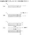
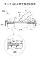
図1A及びBは、本発明に係る第1の実施例としての多機能圧電アクチュエータ1の構成例を示す斜視図及び断面図である。
この実施例では、給電用の電極と共通電極との間に接合された第1の圧電素子と、共通電極と信号検出用の電極との間に接合された第2の圧電素子とを備え、給電用の電極と共通電極との間に所定の電圧を供給し、検出用の電極から、外力に基づく力検出信号を取り出すようにして、給電用の電極と共通電極との間に供給された所定の電圧に基づいて振動する圧電バイモルフ型のアクチュエータと、外力に基づく力検出信号を出力する力検出センサとを複合した圧電複合装置を提供できるようにしたものである。1A and 1B are a perspective view and a cross-sectional view showing a configuration example of a multi-function
In this embodiment, the first piezoelectric element joined between the power supply electrode and the common electrode, and the second piezoelectric element joined between the common electrode and the signal detection electrode, A predetermined voltage is supplied between the power supply electrode and the common electrode, and a force detection signal based on an external force is extracted from the detection electrode, and is supplied between the power supply electrode and the common electrode. A piezoelectric composite device in which a piezoelectric bimorph actuator that vibrates based on a predetermined voltage and a force detection sensor that outputs a force detection signal based on an external force can be provided.
図1Aに示す結線固定型の多機能圧電アクチュエータ1は圧電複合装置の一例であり、圧電アクチュエータ機能と力検出センサ機能とを有するものである。多機能圧電アクチュエータ1は、図1Bに示すように、少なくとも、1つの積層体が電気的に2つ単層圧電体4a及び4bに区分(分割)されて構成される。多機能圧電アクチュエータ1は、給電用の電極(以下給電電極という)2と、共通電極6と、信号検出用の電極(以下検出電極という)8とを有している。給電電極2と共通電極6との間には第1の圧電素子3が接合されて、一方の単層圧電体4aを構成する。単層圧電体4aで給電電極2と共通電極6との間には所定の電圧Vaが供給され、圧電アクチュエータとして機能される。 A fixed connection type multifunctional
また、共通電極6と検出電極8との間には第2の圧電素子7が接合されて、他方の単層圧電体4bが構成される。この検出電極8からは、外力に基づく力検出信号(以下で力検出電圧Vdともいう)が取り出され、力検出センサとして機能される。多機能圧電アクチュエータ1は、3つの端子9a,9b,9cを有している。第1の端子9aは給電電極2に接続される。この端子9aには引き出し線L1が接続される。第2の端子9bは共通電極6に接続される。この端子9bには引き出し線L2が接続される。第3の端子9cは検出電極8に接続される。この端子9cには引き出し線L3が接続される。 A second
上述のように多機能圧電アクチュエータ1を構成して、引き出し線L1と引き出し線L2にアクチュエータ制御手段を接続し、第1の圧電素子3に端子9a,9b,9c及び端子9a,9b,9cを介して給電すると、第1の圧電素子3が振動する。また、外力が第2の圧電素子7に加わると、引き出し線L3に検出電圧Vdを出力するようになされる。これにより、給電電極2と共通電極6との間に供給した所定の電圧Vaにより変調を受けた外力に基づく力検出信号(検出電圧Vd)のみを取り出せるようにすれば、両機能を同時に使用可能な低電圧駆動型の多機能アクチュエータ等を提供することができる。 The multi-function
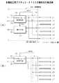
図2は、多機能圧電アクチュエータ1のフィードバック制御例を示すブロック図である。
この例では、給電電極2、共通電極6及び検出電極8の各々に接続された制御装置50を備え、制御装置50は、予め設定された制御目標値(yo,Fo)に応じて給電電極2と共通電極6との間に給電し、及び、検出電極8から力検出信号を検出するように動作する(第1の制御方法)。FIG. 2 is a block diagram illustrating an example of feedback control of the multifunction
In this example, the
図2に示す制御装置50は、アクチュエータ制御手段15、検出演算部17’及び比較器19を備え、制御信号の一例を構成する制御目標値(yo,Fo)に基づいて多機能圧電アクチュエータ1のフィードバック制御(サーボ制御;クローズドループアクチュエータ制御)を実行する。制御目標値yoは変位であり、制御目標値Foは力である。yは多機能圧電アクチュエータ1の動作による変位を示し、Fはアクチュエータの動作によって生じる力を各々示している。一般的に、物体の位置決めを制御する場合であって、制御量として変位yを選択し、アクチュエータが他の物体等に及ぼす力Fを制御する場合は、制御量として力Fを選択する。 A
この例で、アクチュエータ制御手段15には、図1Aに示した引き出し線L1を介して給電電極2が接続される。アクチュエータ制御手段15は、予め与えられた制御目標値yoまたはFoに基づいて、指令電圧を決定し、多機能圧電アクチュエータ1でアクチュエータとして機能する単層圧電体4aに指令電圧を印加するようになされる。 In this example, the
上述の検出電極8と検出演算部17’との間は、図1Aに示した引き出し線L3により接続される。検出演算部17’は検出手段の一例であり、押下力F’を検出して、検出電極8から出力される検出電圧Vdを2つの制御量に変換するようになされる。検出演算部17’には、検出電圧Vd(=v)と変位y、又は、検出電圧Vd(=v)と力Fの関係を定義した関数y=f(v)、F=g(v)、または、変換テーブルが予め備えられる。 The
変換テーブルは、例えば、電圧v=1,2,3,4・・・に対して、変位y=0.2,0.4,0.6,0.8・・・[mm]と、力F=3,6,9,12・・・[gf]等が格納されている。変換後の制御量をy1またはF1とする。検出演算部17’には比較器19が接続され、変換後の制御量y1またはF1と制御目標値(yo,Fo)とが比較される。比較結果は、アクチュエータ制御手段15に出力され、新たな指令電圧が決定される。For example, for the voltage v = 1, 2, 3, 4..., The displacement y = 0.2, 0.4, 0.6, 0.8. F = 3, 6, 9, 12,... [Gf] and the like are stored. The control amount after the conversion is y1 or F1 . A comparator 19 is connected to the
アクチュエータ1が動作し、押下力F’が加わった結果、力検出センサとして機能する圧電素子7に生じる検出電圧Vdは、検出演算部17’に出力される。ここで検出電圧Vdは、検出演算部17’で必要な制御量y1またはF1に変換された後、比較器19において目標値(yo,Fo)と比較される。この比較結果で、アクチュエータ制御手段15では、新たな指令電圧が決定される。この新たな指令電圧は、多機能圧電アクチュエータ1でアクチュエータとして機能する圧電素子3に印加される。As a result of the
ここで、本発明による多機能圧電アクチュエータ1では、単層圧電体4aと単層圧電体4bとは、機械的には同一の構造体の中にあり、密着している一方で、電気的には共通電極6を境に独立している。この点で、圧電バイモルフ型のアクチュエータとして機能する多機能圧電アクチュエータ1の一部を力検出センサとして使用できるようになる。従って、アクチュエータ機能と力検出センサ機能とを同時に使用することができる。しかも、アクチュエータと力検出センサとを個別に設ける場合に比べて取り付けスペースの共有化が図られ、電子機器のコンパクト化を図ることができる。 Here, in the multifunction
図3及び図4は、多機能圧電アクチュエータ1の形成例(その1、2)を示す工程図である。
この実施例では、図1AやB等に示した圧電素子3及び圧電素子7として使用するフィルム状圧電体1’を形成し、その後、このフィルム状圧電体1’の一方の面に、給電電極2と検出電極8となる電極パターン2aを形成する。更に、電極パターン2a付きのフィルム状圧電体1’を所望の大きさに切断する。そして、所望の大きさに切断された電極パターン付きのフィルム状圧電体1’を共通電極用の導電部材6aの表裏面に接合する。その後、給電電極2、共通電極6及び検出電極8に引出し線L1〜L3を接続する場合を例に挙げる。3 and 4 are process diagrams showing formation examples (Nos. 1 and 2) of the multifunction
In this embodiment, a film-like
これらを製造条件にして、まず、図3Aにおいて、圧電素子3及び圧電素子7として使用するためのフィルム状圧電体1’を形成する。例えば、粉末状のセラミック等の圧電体材料と溶媒とバインダーと分散材等とを所定の混合比により混合して、図示しない混合スラリーを形成する。溶媒には、アセトン、トルエン、エタノール、MEK等を使用し、バインダーにはポリビニール、アルコール、ポリエタレン等を使用する。バインダーには10w%程度のものを使用する。 Using these as manufacturing conditions, first, in FIG. 3A, a film-like
次に、混合スラリーを一様な厚さに流し出す。膜厚は、例えば、30μm乃至50μm程度にする。その後、溶媒を蒸発乾燥させてフィルム状圧電体(グリーンシート)1’を生成する。フィルム状圧電体1’は30μm程度というように薄いので積層工程に至るまで高分子フィルムにより裏打ちされる。乾燥室を常温又は室内温度を50乃至80℃程度に維持して、一様な厚さに流し出された混合スラリーを数十分間程度放置して乾燥する。溶媒が抜けた混合スラリーは、フィルム状圧電体1’となる。 Next, the mixed slurry is poured out to a uniform thickness. The film thickness is, for example, about 30 μm to 50 μm. Thereafter, the solvent is evaporated and dried to produce a film-like piezoelectric body (green sheet) 1 ′. Since the film-like
そして、図3Bに示すようにフィルム状圧電体1’の一方の面に電極パターン2aを形成する。この工程前には、スルーホールを開口する工程も含まれる。電極パターン2aは、例えば、フィルム状圧電体1’の所定の位置に電極材料を印刷することで形成される。電極印刷はスクリーン印刷によって施される。電極材料には、Ag−Pd合金ペーストが使用される。電極パターン2aは、後工程で給電電極2や検出電極8等となる。 Then, as shown in FIG. 3B, an electrode pattern 2a is formed on one surface of the film-like piezoelectric body 1 '. Prior to this step, a step of opening a through hole is also included. The electrode pattern 2a is formed, for example, by printing an electrode material on a predetermined position of the film-like piezoelectric body 1 '. Electrode printing is performed by screen printing. An Ag—Pd alloy paste is used as the electrode material. The electrode pattern 2a becomes the
次に、図3Cにおいて、先に電極材料が印刷されたフィルム状圧電体1’を所望の大きさに切断する。例えば、図示しない切断装置を使用してフィルム状圧電体1’を短冊状に切断する。これは給電電極付きの圧電素子3及び検出電極付きの圧電素子7等を得るためである。そして、図3Cにおいて、給電電極付きの圧電素子3を構成する単層状のフィルム状圧電体1’や、検出電極付きの圧電素子7を構成する単層状のフィルム状圧電体1’を乾燥してバインダーを除去するようになされる。このときの乾燥条件は、常温又は室内温度を400℃乃至500℃程度に維持して、フィルム状圧電体1’を数十分間程度放置して脱脂する。実際には、炉内で昇温レートをコントロールして数日を要して温度を400℃乃至500℃程度にまで温度を上げる。 Next, in FIG. 3C, the film-like piezoelectric body 1 'on which the electrode material has been printed is cut into a desired size. For example, the film-like
また、先にバインダーが除去された単層状のフィルム状圧電体1’を焼成する。このときの焼成条件は、焼成温度が10℃乃至1200℃程度で、焼成時間は60分程度である。このときも脱脂処理を同様にして、焼成炉内で昇温レートをコントロールして数日を要して温度を10℃乃至1200℃程度にまで温度を上げる。 Further, the monolayer film-like
次に、給電電極付きの圧電素子3を構成する単層状のフィルム状圧電体1’や、検出電極付きの圧電素子7を構成する単層状のフィルム状圧電体1’に適合する大きさの共通電極用の導電部材6aを準備する。導電部材6aは、例えば、給電電極2や検出電極8よりも大きく切断される。これは共通電極6となる導電部材6aの一端に半田付け代を確保するためである。 Next, the common size of the single-layered film-like
そして、図4Aに示す共通電極用の導電部材6aの表面に給電電極付きのフィルム状圧電体1’を接着する。このとき、裏打ち用の高分子フィルムを剥がして共通電極6の一方の面に圧電素子3を接着する。給電電極2は上に向ける。その導電部材6aの裏面に検出電極付きのフィルム状圧電体1’を接着する。この共通電極6の他方の面には圧電素子7を接着する。圧電素子7は、圧電素子3と反対向き、つまり、検出電極8が下に向くように貼り合わされる。これにより、給電電極2と共通電極6との間に圧電素子3を接合することができる。また、共通電極6と検出電極8との間に圧電素子7を接合することができる。なお、接着材には、エポキシ樹脂やUV接着剤が使用される。 Then, a film-like
その後、図4Bにおいて、圧電アクチュエータあるいは力検出センサとして機能させるために必要な引き出し線L1〜L3を給電電極2、共通電極6及び検出電極8の各々に半田付けする。圧電素子3の上面は給電電極2で覆われ、その端子9aには引き出し線L1が半田付けされる。引き出し線L1は、給電電極2と共通電極6との間に所定の電圧を供給する際に使用される。 Thereafter, in FIG. 4B, lead lines L1 to L3 necessary for functioning as a piezoelectric actuator or a force detection sensor are soldered to the
共通電極6の端子9bには引き出し線L2が半田付される。引き出し線L2は接地(GND)して使用される。圧電素子7の下面は検出電極8で覆われ、その端子9cには引き出し線L3が半田付けされる。引き出し線L3は、検出電極8と共通電極6との間で力検出信号(検出電圧Vd)を検出する際に使用される。これにより、図1AやB等に示した多機能圧電アクチュエータ1が完成する。その後、必要に応じて圧電素子の分極処理を行う。分極処理とは、外部磁化を加えて圧電素子の分子磁石の向きを一定方向に揃える処理をいう。 A lead line L2 is soldered to the terminal 9b of the
これにより、給電電極2と共通電極6との間に供給された所定の電圧Vaに基づいて振動する圧電バイモルフ型のアクチュエータと、押圧力F’に基づく力検出信号を出力する力検出センサとを複合した多機能圧電アクチュエータ1を製造することができる。 Thus, a piezoelectric bimorph actuator that vibrates based on a predetermined voltage Va supplied between the
このように第1の実施例としての多機能圧電アクチュエータ、その制御方法及びその製造方法によれば、給電電極2と共通電極6との間に圧電素子3が接合され、その共通電極6と検出電極8との間には圧電素子7が接合されている。この積層構造を前提にして、給電電極2と共通電極6との間には制御装置50から所定の電圧Vaが供給され、検出電極8から、外力(押下力F’)に基づく検出電圧Vdが取り出される。 As described above, according to the multifunction piezoelectric actuator, the control method, and the manufacturing method thereof as the first embodiment, the
従って、給電電極2と共通電極6との間に接合された圧電素子3による単層圧電体4aによってアクチュエータ機能を構成することができ、共通電極6と検出電極8との間に接合された圧電素子7による単層圧電体4bによって力検出機能を構成することができる。 Therefore, the actuator function can be configured by the single-layer piezoelectric body 4 a formed by the
この構成によって、周波数50Hz〜500Hzの交流を含む所定電圧Vaに基づいて振動する圧電バイモルフ型のアクチュエータと、押下力F’を検出する力検出センサとを複合した多機能圧電アクチュエータ1を提供することができる。しかも、アクチュエータと力検出センサとが同一構造体内に形成されるので、これらを個別に設ける場合に比べて取り付けスペースを共有することができ、電子機器のコンパクト化を図ることができる。 With this configuration, it is possible to provide a multifunctional
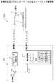
図5A及びBは、第2の実施例としての多機能圧電アクチュエータ(結線固定型)10の構成例を示す図である。図5Aはその構成例を示す斜視図、図5BはそのX1−X2矢視断面図である。 FIGS. 5A and 5B are diagrams showing a configuration example of a multifunction piezoelectric actuator (connection fixed type) 10 as a second embodiment. 5A is a perspective view showing an example of the configuration, and FIG. 5B is a cross-sectional view taken along arrow X1-X2.
第2の実施例では、2層以上のひずみ量の異なる圧電素子、あるいは圧電素子と非圧電素子とを貼り合わせ、圧電素子に電圧を印加した際に、双方のひずみ量の差によって生じる、貼合体の曲げ変形を力学的に利用するアクチュエータに関して、一以上の圧電素子を積層した2つの積層体と、これらの積層体の間に積層された一以上の圧電素子を有する他の積層体とを備え、前者の2つの積層体の引出し電極に給電して一以上の圧電素子を振動できるようにすると共に、後者の積層体に力が加わったときは、その引出し電極から力検出信号を出力できるようにしたものである。 In the second embodiment, when two or more layers of piezoelectric elements having different strain amounts, or a piezoelectric element and a non-piezoelectric element are bonded together and a voltage is applied to the piezoelectric elements, the bonding is caused by the difference in strain amount between the two. Regarding an actuator that dynamically utilizes bending deformation of a combination, two laminated bodies in which one or more piezoelectric elements are laminated, and another laminated body having one or more piezoelectric elements laminated between these laminated bodies It is possible to supply power to the extraction electrodes of the former two laminates so that one or more piezoelectric elements can vibrate, and when a force is applied to the latter laminate, a force detection signal can be output from the extraction electrodes. It is what I did.
図5Aに示す多機能圧電アクチュエータ10は、圧電複合装置の一例であり、圧電アクチュエータ機能と力検出センサ機能とを有するものである。多機能圧電アクチュエータ10は、図5Bに示すように、少なくとも、1つの積層体14が電気的に3つ積層圧電体群14a,14b,14cに区分(分割)されて構成されている。 A multifunction
この例で積層圧電体群14cの中央に位置する圧電素子から引き出された中央電極13を力検出用とし、その積層圧電体群14cの両側に位置する他の積層圧電体群14a、14bの圧電素子から引き出された電極を給電用となされる。この例では、電気的に分割された1つ又はそれ以上の積層圧電体群14a、14b、14cのうち曲げ変形する際の中立面に近い位置の積層圧電体群14cを力検出用とし、中立面から離れた位置の積層圧電体群14a、14bをアクチュエータ用となされる。 In this example, the
この例で積層圧電体群14cの中央に位置する圧電素子から引き出された中央電極13は力検出センサに使用し、その積層圧電体群14cの両側に位置する他の積層圧電体群14a、14bの圧電素子から引き出された電極は、アクチュエータの給電に使用するようになされる。この例では、電気的に分割された1つ又はそれ以上の積層圧電体群14a、14b、14cのうち曲げ変形する際の中立面に近い位置の積層圧電体群14cを力検出センサに使用し、中立面から離れた位置の積層圧電体群14a、14bをアクチュエータとして使用するようになされる。 In this example, the
第1の積層圧電体群14aは第1の積層体の一例であり、引出し電極(以下上部表面電極11という)と圧電素子とを一以上積層したものである。各々の圧電素子は電極と圧電体から構成される。第2の積層圧電体群14bは、第2の積層体の一例であり、引出し電極(以下下部表面電極12という)と圧電素子とを一以上積層したものである。各々の圧電素子は電極と圧電体から構成される。上部表面電極11と下部表面電極12とは積層体内部で結線される。他の電極も積層体内部で結線されている。 The first laminated
第3の積層圧電体群14cは第3の積層体の一例であり、積層圧電体群14aと積層圧電体群14bとの間に積層されており、一以上の圧電素子を有している。積層圧電体群14cは、他の引出し電極の一例となる中央電極13を有している。中央電極13は、積層圧電体群14aと積層圧電体群14bに対して、及び、積層圧電体群14cの曲げ変形の中立面に位置している。 The third laminated
結線固定型の多機能圧電アクチュエータ10は、4つの端子16a〜16dを有している。第1の端子16aは上部表面電極11に接続される。この端子16aには引き出し線L1が接続される。第2の端子16bは積層圧電体群14bの引出し電極に接続される。この端子16bには引き出し線L2が接続される。第3の端子16cは積層圧電体群14bの引出し電極に接続される。この端子16cには引き出し線L3が接続される。第4の端子16dは積層圧電体群14cの引出し電極に接続される。この端子16dには引き出し線L4が接続される。 The fixed connection type
結線固定型の多機能圧電アクチュエータ10は上述のように構成する。そして、引き出し線L1と引き出し線L2にアクチュエータ制御手段を接続し、積層圧電体群14a及び積層圧電体群14bの圧電素子に端子16a及び端子16bを介して給電すると、積層圧電体群14aと積層圧電体群14bとが振動する。また、積層圧電体群14cの圧電素子は外力が加わると、引き出し線L3及び引き出し線L3に検出電圧Vdを出力する。 The fixed connection type multi-function
このように、第2の実施例に係る多機能圧電アクチュエータ及びその取扱方法によれば、一以上の圧電素子を積層して形成された積層体を1つ又はそれ以上に電気的に分割し、電気的に分割された1つ又はそれ以上の積層圧電体群14cを圧電素子に加えられる外力を検知するための力検出センサとして機能させるようになされる。 As described above, according to the multifunction piezoelectric actuator and the handling method thereof according to the second embodiment, the laminate formed by laminating one or more piezoelectric elements is electrically divided into one or more, The one or more laminated
従って、圧電バイモルフ型のアクチュエータとして機能する多機能圧電アクチュエータ10の一部を力検出センサとして使用できるので、アクチュエータ機能と力検出センサ機能を同時に使用することができる。このような機能を組み合わせた複合機能を実現することができる。これにより、両機能を同時に使用可能な低電圧駆動型の多機能アクチュエータ10等を提供することができる。しかも、アクチュエータと力検出センサとが同一構造体内に形成されるので、これらを個別に設ける場合に比べて取り付けスペースを共有することができ、電子機器のコンパクト化を図ることができる。 Accordingly, since a part of the multifunction
図6は、第3の実施例としての結線可変型の多機能圧電アクチュエータ100の断面の構成例及びその内部結線例を示す図である。
第3の実施例で、結線可変型の多機能圧電アクチュエータ100は、結線固定型に比べて3本多い7本の引き出し線L1〜L7を有している。図6に示す多機能圧電アクチュエータ100は、積層体全部を圧電アクチュエータとしてのみ機能させたり、積層体全部を圧電アクチュエータ+力検出センサとして同時に機能させるものである。FIG. 6 is a diagram illustrating a cross-sectional configuration example and internal connection example of a variable connection type multifunctional
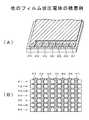
In the third embodiment, the variable connection type multifunctional
多機能圧電アクチュエータ100は、電極と電極との間に圧電体を積層する形態で、合計18層の圧電体#1〜#18と、上部表面電極11と、下部表面電極12と、中央電極13と、16層の電極IE1〜IE16を有した積層体を少なくとも、電気的に3つ積層圧電体群14a,14b,14cに区分されて構成される。この例でも結線固定型と同様にして、積層圧電体群14cは、積層圧電体群14aと積層圧電体群14bとの間に挟まれる形態を採る。 The multi-function
積層圧電体群14aは、上部表面電極11と、電極IE1〜IE5と、5層の圧電体#1〜#5から構成され、圧電アクチュエータとして機能するようになされる。圧電体#1は上部表面電極11と電極IE1との間に積層され、圧電体#2は電極IE1と電極IE2との間に積層され、圧電体#3は電極IE2と電極IE3との間に積層され、圧電体#4は電極IE3と電極IE4との間に積層され、圧電体#5は電極IE4と引出し電極IE5との間に各々積層される。 The laminated
積層圧電体群14cは、積層圧電体群14aと積層圧電体群14bとの間に積層されており、中央電極13と、電極IE6〜IE8と、4層の圧電体と、電極IE9〜IE11と、4層の圧電体から構成され、力検出センサとして機能するようになされる。圧電体#6は電極IE5と電極IE6との間に積層され、圧電体#7は電極IE6と電極IE7との間に積層され、圧電体#8は電極IE7と電極IE8との間に積層され、圧電体#9は電極IE8と中央電極13との間に積層される。 The laminated
また、圧電体#10は中央電極13と電極IE9との間に積層され、圧電体#11は電極IE9と電極IE10との間に積層され、圧電体#12は電極IE10と電極IE11との間に各々積層される。中央電極13は、積層圧電体群14aと積層圧電体群14bに対して、及び、積層圧電体群14cの曲げ変形の中立面に位置している。 The
積層圧電体群14bは、下部表面電極12と、電極IE13〜IE17と、5層の圧電体から構成され、圧電アクチュエータ100として機能するようになされる。圧電体#13は電極IE11と電極IE12との間に積層され、圧電体#14は電極IE12と電極IE13との間に積層され、圧電体#15は電極IE13と電極IE14との間に積層され、圧電体#16は電極IE14と電極IE15との間に積層され、圧電体#17は電極IE15と電極IE16との間に積層され、圧電体#18は電極IE16と下部表面電極12との間に各々積層されている。 The laminated
図6において、積層圧電体群14aで上部表面電極11と電極IE2と電極IE4とは積層体内部で結線される。上部表面電極11は第1端子16aを介して引き出し線L1に接続される。電極IE1と電極IE3とは積層体内部で引出し電極IE5に結線される。引出し電極IE5は第2端子16bを介して引き出し線L2に接続される。 In FIG. 6, in the laminated
積層圧電体群14cで電極IE8は積層体内部で引出し電極IE6に結線される。引出し電極IE6は端子16cを介して引き出し線L3に接続される。電極IE7と電極IE10とは中央電極13に結線される。中央電極13は端子16dを介して引き出し線L4に接続される。電極IE9は積層体内部で引出し電極IE11に結線される。引出し電極IE11は端子16eを介して引き出し線L5に接続される。 In the laminated
積層圧電体群14bで、電極IE14と、電極IE16とは積層体内部で引出し電極IE12に結線される。引出し電極IE12は端子16fを介して引き出し線L6が接続される。電極IE13と電極IE15とは積層体内部で下部表面電極12に結線される。下部表面電極12は端子16gを介して引き出し線L7に接続される。 In the multilayer
なお、図6において、中央電極13付近にある梨地に示す圧電体#8〜#12が力検出センサとして機能し、その上下にある白抜きの圧電体#1〜#5及び圧電体#14〜#18がアクチュエータ100として機能する部分である。圧電体#6及び#13はアクチュエータと力検出センサとの境界に位置しており、緩衝材として機能する。 In FIG. 6, the
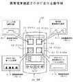
図7A及びBは、多機能圧電アクチュエータ100の制御系の構成例を示すブロック図である。
この例で、積層圧電体群14a〜14cの各々の上部表面電極11、電極IE5、電極IE6、中央電極13、電極IE11、電極IE12、下部表面電極12に接続された制御装置50を備え、制御装置50は、予め設定された制御信号に応じて積層圧電体群14a、14bの各々の上部表面電極11、電極IE5、電極IE12、下部表面電極12に給電し、及び、積層圧電体群14cの電極IE6、中央電極13、電極IE11に給電し、又は、当該電極IE6、中央電極13、電極IE11から力検出信号Soutを検出するようになされる。7A and 7B are block diagrams illustrating a configuration example of a control system of the multifunction
In this example, a
図7Aに示す制御装置50は、アクチュエータ制御手段15、検出手段17及び接続回路18を備えており、多機能圧電アクチュエータ100を圧電アクチュエータ+力検出センサとして同時に機能させる場合である。接続回路18は例えば、MOSFETスイッチ回路を利用したゲートアレイから構成される。アクチュエータ制御手段15は上位の制御系に接続され、その上位の制御系から、例えば、振動波形パターンデータD1と制御信号の一例となる機能選択信号S1とを入力し、これらの振動波形パターンデータD1及び機能選択信号S1に基づいて多機能圧電アクチュエータ100を駆動制御するようになされる。 The
アクチュエータ制御手段15は、例えば、機能選択信号S1が「圧電アクチュエータ+力検出センサとして同時に機能させる」という内容のときは、スイッチ接続信号SS1を接続回路18に出力して、引き出し線L1と引き出し線L7とを接続する。また、引き出し線L1と引き出し線L7とを接続してアクチュエータ制御手段15に各々接続する。これにより、図6に示した端子16a、16b、16f、16gを介して積層圧電体群14a及び積層圧電体群14bの圧電体#1〜#5及び圧電体#14〜#18に至るアクチュエータ回路を構築することができる。 For example, when the function selection signal S1 has the content of “actually function as a piezoelectric actuator + force detection sensor”, the actuator control means 15 outputs the switch connection signal SS1 to the
更に、アクチュエータ制御手段15は、スイッチ接続信号SS1に基づいて引き出し線L3と引き出し線L5とを接続し、引き出し線L4を検出手段17に各々接続する。これにより、図6に示した端子16c、16d、16eを介して積層圧電体群14cの中央電極13及び圧電体#7〜#12に至る力検出センサ回路を構築することができる。 Further, the actuator control means 15 connects the lead line L3 and the lead line L5 based on the switch connection signal SS1, and connects the lead line L4 to the detection means 17, respectively. Thereby, a force detection sensor circuit that reaches the
このようなアクチュエータ回路及び力検出センサ回路が構築された状態で、アクチュエータ制御手段15は、振動波形パターンデータD1に基づくアクチュエータ駆動電圧Vaを発生する。アクチュエータ駆動電圧Vaは、引き出し線L1、L2、L6、L7を通じて、図6に示した端子16a、16b、16f、16gを介して積層圧電体群14a及び積層圧電体群14bの圧電体#1〜#5及び圧電体#14〜#18に給電すると、中央電極13を基準にして、積層圧電体群14aが伸長し、積層圧電体群14bが収縮するようにして振動する。従って、多機能圧電アクチュエータ100をアクチュエータ機能として動作させることができる。 In a state where such an actuator circuit and a force detection sensor circuit are constructed, the actuator control means 15 generates an actuator drive voltage Va based on the vibration waveform pattern data D1. The actuator drive voltage Va is transmitted through the lead lines L1, L2, L6, and L7, and via the
また、この状態、又は、アクチュエータ駆動電圧Vaを供給しない状態で、積層圧電体群14cの圧電体#7〜#12に対して外力が加わると、引き出し線L3及び引き出し線L3に力検出電圧Vdが発生する。この力検出電圧Vdは、検出手段17に出力される。検出手段17では、例えば、力検出電圧Vdが検出され、力検出信号Soutとして上位の制御系に出力するようになされる。従って、多機能圧電アクチュエータ100のアクチュエータ機能を維持しつつ力検出センサとしても動作させることができる。 Further, when an external force is applied to the
図7Bに示す制御系は、多機能圧電アクチュエータ100を圧電アクチュエータとしてのみ機能させる場合である。この場合、アクチュエータ制御手段15は上位の制御系から振動波形パターンデータD1と機能選択信号S1とを入力し、これらの振動波形パターンデータD1及び機能選択信号S1に基づいて多機能圧電アクチュエータ100を駆動制御するようになされる。 The control system shown in FIG. 7B is a case where the multifunctional
アクチュエータ制御手段15は、例えば、機能選択信号S1が「圧電アクチュエータとしてのみ機能させる」という内容のときは、スイッチ接続信号SS2を接続回路18に出力して、引き出し線L1と、L3と、L5と、L7とを接続する。また、引き出し線L2と、L4と、L6とを接続してアクチュエータ制御手段15に各々接続する。これにより、図6に示した端子16a、16b、16c、16d、16e、16f及び16gを介して積層圧電体群14a、積層圧電体群14c及び積層圧電体群14bの圧電体#1〜#18に至るアクチュエータ回路を構築することができる。 For example, when the function selection signal S1 indicates that “functions only as a piezoelectric actuator”, the
このようなアクチュエータ回路が構築された状態で、アクチュエータ制御手段15は、振動波形パターンデータD1に基づくアクチュエータ駆動電圧Vaを発生する。アクチュエータ駆動電圧Vaは、引き出し線L1、L2、L3、L4、L5、L6、L7を通じて、図6に示した端子16a、16b、16c、16d、16e、16f及び16gを介して積層圧電体群14a、積層圧電体群14c及び積層圧電体群14bの圧電体#1〜#18に給電すると、中央電極13を基準にして、積層圧電体群14a及び積層圧電体群14cの上半分が伸長し、その下半分及び積層圧電体群14bとが収縮するように振動する。従って、多機能圧電アクチュエータ100に関して積層体全部をアクチュエータ機能として動作させることができる。 In a state where such an actuator circuit is constructed, the actuator control means 15 generates an actuator drive voltage Va based on the vibration waveform pattern data D1. The actuator driving voltage Va is supplied through the lead lines L1, L2, L3, L4, L5, L6, and L7, and through the
このように第3の実施例に係る多機能圧電アクチュエータの制御方法によれば、制御装置50は、18層の圧電体#1〜#18を積層した積層圧電体群14a,14b,14cの上部表面電極11、電極IE5、電極IE6、中央電極13、電極IE11、電極IE12、下部表面電極12の各々に接続される。制御装置50は、予め設定された機能選択信号SS1等に応じて積層圧電体群14a,14bの各々の上部表面電極11、電極IE5、電極IE12、下部表面電極12に給電し、積層圧電体群14cの電極IE6、中央電極13、電極IE11から検出電圧Vdを検出するようになされる。 As described above, according to the control method of the multi-function piezoelectric actuator according to the third embodiment, the
この結果で、積層圧電体群14a、14bによってアクチュエータ機能を構成することができ、積層圧電体群14cによって力検出機能を構成することができる。また、積層圧電体群14a,14b,14cの上部表面電極11、電極IE5、電極IE6、中央電極13、電極IE11、電極IE12、下部表面電極12の各々に給電すると、積層圧電体群14a,14b,14cによってアクチュエータ機能を構成することができる。従って、力検出機能させた積層圧電体群14cの圧電体#7〜#12を状況に応じてアクチュエータとして機能させるといった機能切り替え制御を実行できるようになる。 As a result, the actuator function can be configured by the multilayered
図8は、多機能圧電アクチュエータ100のフィードバック制御例を示すブロック図である。
図8に示す制御装置50は、アクチュエータ制御手段15、検出演算部17’及び比較器19を備え、制御目標値(yo,Fo)に基づいて多機能圧電アクチュエータ100のフィードバック制御(サーボ制御;クローズドループアクチュエータ制御)を実行する。制御目標値yoは変位であり、制御目標値Foは力である。yは多機能圧電アクチュエータ100の動作による変位を示し、Fは当該アクチュエータ100の動作によって生じる力を各々示している。一般的に、物体の位置決めを制御する場合であって、制御量として変位yを選択し、アクチュエータ100が他の物体等に及ぼす力Fを制御する場合は、制御量として力Fを選択する。FIG. 8 is a block diagram illustrating an example of feedback control of the multi-function
The
この例で、アクチュエータ制御手段15には、図7Aに示した引き出し線L1,L2,L6,L7を代表する単線を介して多機能圧電アクチュエータ100が接続される。アクチュエータ制御手段15は、予め与えられた制御目標値yoまたはFoに基づいて、指令電圧を決定し、多機能圧電アクチュエータ100でアクチュエータとして機能する積層圧電体群14a,14bに指令電圧を印加するようになされる。 In this example, the multi-function
上述の多機能圧電アクチュエータ100と検出演算部17’との間は、図7Aに示した引き出し線L3,L4,L5を代表する単線により接続される。検出演算部17’は検出手段の一例であり、多機能圧電アクチュエータ100から出力される検出電圧Vdを2つの制御量に変換するようになされる。検出演算部17’には、検出電圧Vd(=v)と変位y、又は、検出電圧Vd(=v)と力Fの関係を定義した関数y=f(v)、F=g(v)、または、変換テーブルが予め備えられる。 The above-described multifunction
変換テーブルは、例えば、電圧v=1,2,3,4・・・に対して、変位y=0.2,0.4,0.6,0.8・・・[mm]と、力F=3,6,9,12・・・[gf]等が格納されている。変換後の制御量をy1またはF1とする。検出演算部17’には比較器19が接続され、変換後の制御量y1またはF1と制御目標値(yo,Fo)とが比較される。比較結果は、アクチュエータ制御手段15に出力され、新たな指令電圧が決定される。For example, for the voltage v = 1, 2, 3, 4..., The displacement y = 0.2, 0.4, 0.6, 0.8. F = 3, 6, 9, 12,... [Gf] and the like are stored. The control amount after the conversion is y1 or F1 . A comparator 19 is connected to the
アクチュエータ100が動作した結果、力検出センサとして機能する積層圧電体群14cに生じる検出電圧Vdは、検出演算部17’に出力される。ここで検出電圧Vdは、検出演算部17’で必要な制御量y1またはF1に変換された後、比較器19において目標値(yo,Fo)と比較される。この比較結果で、アクチュエータ制御手段15では、新たな指令電圧が決定される。この新たな指令電圧は、多機能圧電アクチュエータ100でアクチュエータとして機能する積層圧電体群14a,14bに印加される。As a result of the operation of the
ここで、本発明による多機能圧電アクチュエータ100では、アクチュエータとして機能する圧電体と、センサとして機能する圧電体は、機械的には同一の構造体の中にあり、密着している一方で、電気的には独立している。この点で、圧電バイモルフ型のアクチュエータとして機能する多機能圧電アクチュエータ100の一部を力検出センサとして使用できるようになる。従って、アクチュエータ機能と力検出センサ機能とを同時に使用することができる。しかも、アクチュエータ100と力検出センサとを個別に設ける場合に比べて取り付けスペースの共有化が図られ、電子機器のコンパクト化を図ることができる。 Here, in the multi-function
図9、図10、図13〜図15は、多機能圧電アクチュエータ100の形成例(その1〜5)を示す工程図である。図11及び図12は、それを補足する電極パターン例及びフィルム状圧電体の積層例を示す図である。 9, 10, and 13 to 15 are process diagrams showing formation examples (1 to 5) of the multifunction
第3の実施例では、図6に示したような上部表面電極11と、下部表面電極12と、中央電極13と、16層の電極IE1〜IE16とを有した積層体を形成し、その後、積層体を電気的に分割して、少なくとも、3個の積層圧電体群14a、14b、14cを画定し、画定後の積層圧電体群14cの中央に位置する圧電体)#9、#10から中央電極13を引出し、この中央の積層圧電体群14cの両側に位置する他の積層圧電体群14a、14bの圧電体#5、#6から他の電極IE5、IE6を引き出すようになされる。つまり、中央に位置する積層圧電体群14aから、少なくとも、2本の電極IE6、IE11及び1本の中央電極13を引き出すようになされる。 In the third embodiment, a laminated body having the
これらを製造条件にして、図9Aにおいて、粉末状のセラミック等の圧電体材料と溶媒とバインダーと分散材等とを所定の混合機101に投入して混合し、混合スラリー102を形成する。溶媒には、アセトン、トルエン、エタノール、MEK等を使用し、バインダーにはポリビニール、アルコール、ポリエタレン等を使用する。バインダーには10w%程度のものを使用する。 Under these manufacturing conditions, in FIG. 9A, a piezoelectric material such as powdered ceramic, a solvent, a binder, a dispersion material, and the like are charged into a predetermined mixer 101 and mixed to form a mixed slurry 102. Acetone, toluene, ethanol, MEK, or the like is used as the solvent, and polyvinyl, alcohol, polyethylene, or the like is used as the binder. A binder of about 10 w% is used.
次に、図9Bにおいて、ドクターブレード103を使用して、混合スラリー102を一様な厚さに流し出す。例えば、膜厚が30乃至50μm程度になるようにする。その後、溶媒を蒸発乾燥させてグリーンシートを生成する。例えば、乾燥室104を常温又は室内温度を50乃至80℃程度に維持して、一様な厚さに流し出された混合スラリー102を数十分間程度放置して乾燥する。溶媒が抜けた混合スラリー102は、フィルム状圧電体(グリーンシート)100’となる。 Next, in FIG. 9B, using the doctor blade 103, the mixed slurry 102 is poured out to a uniform thickness. For example, the film thickness is set to about 30 to 50 μm. Thereafter, the solvent is evaporated and dried to produce a green sheet. For example, the drying
その後、所定の大きさにフィルム状圧電体100’をカットし、図9Cにおいて、そのフィルム状圧電体100’を所定のフレーム105に装着する。カットする形状は正方形であって、その大きさは200mm×200mm程度である。 Thereafter, the film-shaped
次に、図10Aにおいて、先にフレーム105に装着されたフィルム状圧電体100’の所定の位置を開口して図示しないスルーホールを形成する。このスルーホールは、各層にある主電極IEを表面に設けられた配線用電極(ランド)と電気的に接合するために開口される。開口径は0.1μmφ乃至0.2μmφ程度である。 Next, in FIG. 10A, a predetermined position of the film-like
更に、図10Bにおいて、先にスルーホールが開口されたフィルム状圧電体100’の所定の位置に電極材料を印刷する。電極印刷はスクリーン印刷によって施される。電極材料には、Ag−Pd合金ペーストが使用される。各層の電極印刷に関しては、図11A〜Dに示す4種類の電極パターンP1〜P4が得られるようなスクリーンが準備される。各スクリーンには、基本的に1枚の主電極IEと、例えば、4個の配線用電極(ランド)とが配置される。ランドは、層間の接続用の開口部(スルーホール)に位置合わせするようになされる。主電極IEは、各層でそれぞれ異なる位置にあるランドR1、R2、R3又はR4と接続されるようにスクリーンが形成されている。 Further, in FIG. 10B, an electrode material is printed at a predetermined position of the film-like
図11Aに示す電極パターンP1は、主電極IEと第1のランドR1とが接続される。積層圧電群14aにおいて、電極パターンP1は上部表面電極11、電極IE2及びIE4に適用される。第1のランドR1は端子16aとなる。積層圧電群14bにおいて、電極パターンP1は下部表面電極12、電極IE15及びIE13に適用され、ランドR1は端子16gとなる。 In the electrode pattern P1 shown in FIG. 11A, the main electrode IE and the first land R1 are connected. In the laminated
図11Bに示す電極パターンP2は、主電極IEと第2のランドR2とが接続される。積層圧電群14aにおいて、電極パターンP2は、電極IE1、IE3及びIE5に適用される。ランドR2は端子16bとなる。積層圧電群14bにおいて、電極パターンP2は、電極IE16、IE14及びIE12に適用される。ランドR2は端子16fとなる。 In the electrode pattern P2 shown in FIG. 11B, the main electrode IE and the second land R2 are connected. In the laminated
図11Cに示す電極パターンP3は、主電極IEと第3のランドR3とが接続される。積層圧電群14aにおいて、電極パターンP3は、電極IE6及びIE8に適用され、ランドR3は端子16cとなる。積層圧電群14bにおいて、電極パターンP3は電極IE9及びIE11に適用され、ランドR3は端子16eとなる。 In the electrode pattern P3 shown in FIG. 11C, the main electrode IE and the third land R3 are connected. In the laminated
図11Dに示す電極パターンP4は、主電極IEと第4のランドR4とが接続される。積層圧電群14aにおいて、電極パターンP4は、電極IE7に適用され、ランドR4は中央電極13に接続されて端子16dとなる。積層圧電群14bにおいて、電極パターンP4は電極IE10に適用され、ランドR4は上述の中央電極13に接続されて端子16dとなる。なお、各ランドR1〜R4のほぼ中央部には、図10Aで開口したスルーホールが開けられており、電極の印刷の際には、このスルーホール内部にも、十分な量の電極材料を供給するため、複数回印刷を繰り返すとよい。 In the electrode pattern P4 shown in FIG. 11D, the main electrode IE and the fourth land R4 are connected. In the laminated
その後、図10Cにおいて、先に電極材料が印刷されたフィルム状圧電体100’を所定の枚数だけ貼合面と平行に層状に積層する。この例では、電極材料が印刷された9枚のフィルム状圧電体100’によって積層圧電体群14aを形成し、同様にして、9枚のフィルム状圧電体100’によって積層圧電体群14bを形成する。 Thereafter, in FIG. 10C, a predetermined number of film-like piezoelectric bodies 100 'on which the electrode material has been printed are stacked in layers in parallel with the bonding surface. In this example, the laminated
この例では図12に示すように、積層圧電体群14a及び積層圧電体群14bとも、上方から電極パターンP1、P2、P1、P2、P1、P2、P3、P4、P3の順にフィルム状圧電体100’を積層する。この積層によって、アクチュエータ及び力検出センサの機能ユニット毎に一層おきに同一の電極パターン(主電極IEとランドともに)を割り当てられるので、内部的に同質の電極パターンを接続できるようになる。図12は、スルーホール部の形成例を示した断面図である。各層のランドR1〜R4は、スルーホール内に充填される電極材料によって接続される。このようにすると、各層の主電極IEへの給電点を上部表面層に引き出すことができる。 In this example, as shown in FIG. 12, the laminated
次に、図13Aにおいて、先に電極材料が印刷された9枚のフィルム状圧電体100’を熱圧着して積層状のグリーンシート(積層素材)100”を形成する。このときの熱加圧条件は、温度が60℃乃至100℃程度であって、加圧力は100kg/cm2程度であって、熱圧着時間は数十分程度である。Next, in FIG. 13A, the nine film-like
その後、図13Bにおいて、先に熱圧着された積層状のグリーンシート100”を所定の大きさに切断する。例えば、図示しない切断装置を使用してグリーンシート100”を短冊状に切断する。これは積層圧電体群14a及び積層圧電体群14b等を得るためである。そして、図13Cにおいて、積層状のグリーンシート100”を乾燥室104に搬入し、その乾燥室104でグリーンシート100”の中からバインダーを除去するようになされる。このときの乾燥条件は、常温又は室内温度を400℃乃至500℃程度に維持して、グリーンシート100”を数十分間程度放置して脱脂する。実際には、炉内で昇温レートをコントロールして数日を要して温度を400℃乃至500℃程度にまで温度を上げる。 Thereafter, in FIG. 13B, the laminated
また、図14Aにおいて、先にバインダーが除去された積層状のグリーンシート100”を焼成装置106に搬入して焼成する。このときの焼成条件は、焼成温度が1000℃乃至1200℃程度で、焼成時間は60分程度である。このときも脱脂処理を同様にして、焼成炉内で昇温レートをコントロールして数日を要して温度を1000℃乃至1200℃程度にまで温度を上げる。 14A, the laminated
その後、図14Bにおいて、先に焼成された積層状のグリーンシート100”を砥石107で切断して個々の積層圧電体群14a、14bを形成する。40は砥石107の軌跡である。砥石107はグリーンシート100”の表裏を一周りするようにして切断される。これにより、図14Cに示すような積層圧電体群14aが得られる。積層圧電体群14bには、積層圧電体群14aが使用される。 14B, the previously fired laminated
そして、図15Aにおいて、所定の大きさの中央電極13を準備すると共に、この中央電極13の両側に積層圧電体群14a,14bを接着する。このとき、中央電極13の一方の面に積層圧電体群14aを接着し、中央電極13の他方の面に積層圧電体群14bを接着する。積層圧電体群14bは、積層圧電体群14aと反対向き、つまり、各層の主電極IEへの給電点が引き出された上部表面層が下に向くように貼り合わされる。接着材には、エポキシ樹脂やUV接着剤が使用される。 15A, a
その後、図15Bにおいて、圧電アクチュエータあるいは力検出センサとして機能させるために必要な引き出し線L1〜L7を表面に設けられた引出し電極(ランド)に半田付けする。積層圧電体群14aのランドR1は端子16aとなる。この端子16aには引き出し線L1が接合される。ランドR2は端子16bとなる。端子16bには引き出し線L2が接合される。ランドR3は端子16cとなる。端子16cには引き出し線L3が接合される。中央電極13には端子16dが設けられる。端子16cには引き出し線L4が接合される。 Thereafter, in FIG. 15B, lead wires L1 to L7 necessary for functioning as a piezoelectric actuator or a force detection sensor are soldered to lead electrodes (lands) provided on the surface. The land R1 of the multilayer
積層圧電体群14bのランドR3は、端子16eとなる。端子16eには引き出し線L5が接合される。そのランドR2は、端子16fとなる。端子16fには引き出し線L6が接合される。そのランドR1は、端子16gとなる。端子16gには引き出し線L7が各々接合される。これにより、図15Bに示すような多機能圧電アクチュエータ100が完成する。その後、必要に応じて圧電素子の分極処理を行う。 The land R3 of the multilayer
このように、第3の実施例に係る多機能圧電アクチュエータ100の製造方法によれば、上部表面電極11と、下部表面電極12と、中央電極13と、16層の電極IE1〜IE16とを有した積層体を形成し、その後、積層体を電気的に分割して、少なくとも、3個の積層圧電体群14a、14b、14cを画定し、画定後の積層圧電体群14cの中央に位置する圧電体#9、#10から中央電極13を引出し、この中央の積層圧電体群14cの両側に位置する他の積層圧電体群14a、14bの圧電体#5、#6から他の電極IE5、IE6を引き出すようになされる。 Thus, according to the manufacturing method of the multifunction
従って、圧電バイモルフ型のアクチュエータと力検出センサとを同一の構造体内に構成することができる。しかも、各層の主電極IEへの給電点を上部表面層及び下部表面層に引き出すことができる。このことで、アクチュエータ機能と力検出センサ機能を同時に使用可能な低電圧駆動型の多機能アクチュエータ100を製造することができる。これにより、圧電アクチュエータと力検出センサとを個別に設ける場合に比べて取り付けスペースの共有化が図られ、電子機器のコンパクト化を図ることができる。 Therefore, the piezoelectric bimorph actuator and the force detection sensor can be configured in the same structure. In addition, the feeding point to the main electrode IE of each layer can be drawn out to the upper surface layer and the lower surface layer. This makes it possible to manufacture a low-voltage drive
第3の実施例では、初めからアクチュエータ機能及びセンサ機能を多機能圧電アクチュエータ100に組み込む場合について説明したが、これに限られることはない。例えば、他の機能として電荷蓄積機能等を積層体に組み込む場合が生じたときは、図16A〜Gに示すような7種類の電極パターンP1〜P7を形成できるスクリーンを予め準備するとよい。図16A〜Gに示す電極パターンP1〜P7は、7層の主電極IEのいずれもランドR1〜R7を介して上部表面層に引出し可能となるものである。しかも、ランドR1〜R7間を任意に短絡することで、プログラマブルに電極を接続できるようになり、多機能を組み込むことができる。 In the third embodiment, the case where the actuator function and the sensor function are incorporated into the multifunction
図17Aは他のフィルム状圧電体の積層例を示す斜視図である。図17Aに示すランドR1〜R7は、電極パターンP1の上部表面層に引き出されたものである。図17Bは、他のフィルム状圧電体に係るスルーホール部の形成例を示した断面図である。各層のランドR1〜R7は、スルーホール内に充填される電極材料によって接続される。このようにすると、7層の主電極IEへの給電点を全て電極パターンP1の上部表面層に引き出すことができる。 FIG. 17A is a perspective view showing an example of another film-shaped piezoelectric laminate. Lands R1 to R7 shown in FIG. 17A are drawn to the upper surface layer of the electrode pattern P1. FIG. 17B is a cross-sectional view showing an example of forming a through-hole portion according to another film-like piezoelectric body. The lands R1 to R7 of each layer are connected by an electrode material filled in the through hole. In this way, all the feeding points to the seven layers of main electrodes IE can be drawn out to the upper surface layer of the electrode pattern P1.
図18A及びBは、第4の実施例としての第1の入出力装置を応用した携帯端末装置200’の構成例を示す斜視図である。
図18Aに示す携帯端末装置(PDA)200は電子機器の一例であり、本発明に係る第1の入出力装置60’を有している。携帯端末装置200’は、各種電子機器のリモートコントローラ(以下単にリモコンという)や、電子辞書、携帯電話機、デジタルカメラ等に適用して好適である。携帯端末装置200’は、本体20を有している。本体20には複数の機能キー21〜28を有しているが、これらの機能キー21〜28の他に触覚機能付きの入出力装置60’を有している。18A and 18B are perspective views showing a configuration example of a mobile
A portable terminal device (PDA) 200 shown in FIG. 18A is an example of an electronic device, and includes a first input /
入出力装置60’は、タッチカバー付きの多機能圧電アクチュエータ(第1の圧電複合装置)1を有して構成され、タッチカバー28に振動的な変位を与える構造になっている。タッチカバー28は検出電極上を覆うように設けられ、本体20との境目はくびれ部29となされている。この部分にダイヤフラム(スプリング)効果を持たせ、筐体を容易に変形させるためである。タッチカバー28は、絶縁性の樹脂部材で形成される。本体20の樹脂部材を使用して、筐体の一部を成すように、射出一体成形してもよい。多機能圧電アクチュエータ1は、例えば、本体20の側面凹部に接着等により取り付けられる。この例では、多機能圧電アクチュエータ1のアクチュエータ機能を使用者に対する触覚提示に使用し、そのセンサ機能を使用者のスイッチON/OFF情報の入力手段として使用する。 The input /
多機能圧電アクチュエータ1は触覚提示情報確定手段を構成し、タッチカバー28を押下操作する使用者の指30に触覚を提示すると共に、操作者の指30の接触位置における、タッチカバー28に加わる外力を検出して力検出信号(検出電圧Vd)を出力するように動作する。力検出信号は、タッチカバー28が押下されたとき、スイッチON/OFF入力情報を確定する(第1の入出力装置)。 The multi-function
多機能圧電アクチュエータ1は、給電電極2、共通電極6及び検出電極8と、給電電極2と共通電極6との間に接合された圧電素子3と、共通電極6と検出電極8との間に接合された圧電素子7とを備える。多機能圧電アクチュエータ1では、給電電極2と共通電極6との間に所定の電圧が供給され、検出電極8からは、タッチカバー28に加わる外力に基づく力検出信号が取り出される(第1の圧電複合装置)。つまり、多機能圧電アクチュエータ1は入力手段の一例を構成し、操作体の一例となる操作者の指30の接触を検出してスイッチON情報又はOFF情報を出力するように動作する。例えば、操作者の指30がタッチカバー28に触れられ、そこを押下されると、押下力F’が検出され、スイッチON情報(又はスイッチOFF情報)を出力するようになされる。 The multi-function
図19は、入出力装置60’の制御系の構成例を示す回路図である。図19に示す入出力装置60’は、多機能圧電アクチュエータ1、タッチカバー28及び制御装置50’から構成される。図中、波形状で示す部分はダイヤフラムを有している。タッチカバー28は検出電極8上の全面を覆うと共に、その周辺はダイヤフラムを介して本体20に上下動自在に係合される。 FIG. 19 is a circuit diagram illustrating a configuration example of a control system of the input /
この例で、制御装置50’はアンプ等のドライバIC57及びオペアンプ等のコンパレータ58を有して構成される。ドライバIC57は給電電極2に接続され、予め上位の制御系から設定された制御信号Sinに応じて給電電極2と共通電極6との間に所定の電圧Vaを給電する。コンパレータ58は、検出電極8に接続され、この検出電極8から力検出信号Sout(検出電圧Vd)を検出して上位の制御系に出力する。上位の制御系では、コンパレータ58から得られる力検出信号Soutに基づいて給電電極2への給電制御を実行する。 In this example, the
図18Aに示した本体20には表示手段62が備えられる。表示手段62は入力情報を表示する。上位の制御系では、表示手段62に表示された入力項目を選択する操作者の指30の押下力F’を検出し、ここで検出された操作者の指30の押下力F’に基づいて入力項目が選択されたと判断する。上位の制御系では、図19に示した検出電極8から得られる力検出信号に基づいて入力項目が選択されたと判断する。その後、上位の制御系は、制御装置50’へ制御信号Sinを出力する。制御装置50’では、制御信号Sinに基づいて給電電極2への給電制御を実行する。この給電制御により、操作者の指30に触覚刺激を付与するようになされる。 The
このように、第4の実施例としての入出力装置60’を応用した携帯端末装置200’によれば、触覚提示情報確定手段には本発明に係る多機能圧電アクチュエータ(第1の圧電複合装置)1が応用される。多機能圧電アクチュエータ1は、給電電極2、共通電極6及び検出電極8と、給電電極2と共通電極6との間に接合された圧電素子3と、共通電極6と検出電極8との間に接合された圧電素子7とを有する。これを前提にして、入出力装置60’は、操作者の指30の接触位置における押下力F’を検出してスイッチON又はOFF情報を入力する。多機能圧電アクチュエータ1は、タッチカバー28を押下操作する操作者の指30に触覚を提示すると共に、当該操作者の指30の接触位置における押下力F’を検出してスイッチON/OFF情報を確定するようになされる。 As described above, according to the mobile
従って、圧電バイモルフ型のアクチュエータとして機能する圧電複合装置の一部を情報確定用の力検出センサとして利用できるので、アクチュエータ機能と力検出センサ機能を同時に使用することができる。しかも、アクチュエータと力検出センサとを個別に設ける場合に比べて取り付けスペースの共有化が図られ、入出力装置60’及び携帯端末装置200’のコンパクト化を図ることができる。 Accordingly, since a part of the piezoelectric composite device that functions as a piezoelectric bimorph type actuator can be used as a force detection sensor for determining information, the actuator function and the force detection sensor function can be used simultaneously. In addition, the mounting space can be shared as compared with the case where the actuator and the force detection sensor are provided separately, and the input / output device 60 'and the portable terminal device 200' can be made compact.
図20は、第5の実施例としての入出力装置を応用した携帯端末装置200の構成例を示す斜視図である。
図20に示す携帯端末装置(PDA)200は電子機器の一例であり、本発明に係る入出力装置60を有している。携帯端末装置200は、各種電子機器のリモコンや、電子辞書、携帯電話機、デジタルカメラ等に適用して好適である。携帯端末装置200は、本体20を有している。本体20には複数の機能キー21〜28を有しているが、これらの機能キー21〜28の他にブラインドタッチ可能な入出力装置60を有している。FIG. 20 is a perspective view illustrating a configuration example of a mobile
A portable terminal device (PDA) 200 shown in FIG. 20 is an example of an electronic device, and includes an input /
入出力装置60は、タッチパネル61や、表示手段62、4つの多機能圧電アクチュエータ100a〜100d等を有して構成され、タッチパネル61に振動的な変位を与える構造になっている。タッチパネル61は入力手段の一例を構成し、操作体の一例となる操作者の指30の接触位置を検出して入力情報を出力するように動作する。例えば、操作者の指30が表示手段52に表示されたアイコン等を選択してそこに触れると入力情報を出力するようになされる。 The input /
表示手段62には、メニュー画面やアイコンボタン等の入力項目が表示される。表示手段62には液晶表示装置やEL(エレクトロルミネッセンス)素子が使用される。多機能圧電アクチュエータ100a〜100dは触覚提示情報確定手段を構成し、タッチパネル61を操作する使用者の指に触覚を提示すると共に、操作者の指30の接触位置における、タッチパネル61に加わる外力を検出して力検出信号を出力するように動作する。 The display means 62 displays input items such as a menu screen and icon buttons. As the display means 62, a liquid crystal display device or an EL (electroluminescence) element is used. The multi-function
力検出信号は、タッチパネル61で選択された入力情報を確定するようになされる。入出力装置60には多機能圧電アクチュエータ100a〜100dが応用される。この例では、多機能圧電アクチュエータ100のアクチュエータ機能を使用者に対する触覚提示に使用し、そのセンサ機能を使用者の入力情報収集手段として使用する(第2の入出力装置)。 The force detection signal confirms the input information selected on the
図21は、第5の実施例に係る携帯端末装置200における入出力装置60のタッチパネル61、表示手段62、多機能圧電アクチュエータ100a,100bを含む構成例を示す断面図である。タッチパネル61の下方には表示手段62が設けられ、この表示手段62に表示される入力項目は、タッチパネル61を透過して使用者に提示される構造である。 FIG. 21 is a cross-sectional view illustrating a configuration example including the
支持フレーム71の内側には、表示面が露出するように表示手段62が配置され、その支持フレーム71上の4隅(図中では2つのみを示す)には、多機能圧電アクチュエータ100a,100b等が配置されている。左側の多機能圧電アクチュエータ100aは、支持フレーム71上の2つの支持部73a及び73bを枕にして配置され、当該アクチュエータ100aの中央部には支持部73cが設けられている。支持部73aは当該アクチュエータ100aの上端部72bの背面側に配置され、支持部73bは端子16に隣接して配置される。端子16は、図15Bに示した端子16a〜16gを構成する。 Display means 62 is arranged inside the
右側の多機能圧電アクチュエータ100bは、支持フレーム71上の2つの支持部74a及び74bを枕にして配置され、当該アクチュエータ100bの中央部には支持部74cが設けられている。支持部74aは当該アクチュエータ100bの上端部72bの背面側に配置され、支持部74bは端子16に隣接して配置される。端子16は、図15Bに示した端子16a〜16gを構成する。 The right-side multifunction
支持部73c及び74c上にはタッチパネル61が配置される。タッチパネル61は、上部逆L型の側面支持部材70によって支持フレーム71に固定されている。タッチパネル61と側面支持部材70の上端部70a、70bとの間には、シール部材70a及び70bが挟み込まれている。支持部73a〜73c、支持部74a〜74cは、振動伝達機構64を構成する。 A
各々の多機能圧電アクチュエータ100a、100bには、制御装置50が接続されている。例えば、当該アクチュエータ100aの端子16には、図15Bに示した7本の引き出し線L1〜L7が接続される。この引き出し線L1〜L7は制御装置50に接続される。また、多機能圧電アクチュエータ100bの端子16には、図15Bに示した7本の引き出し線L1〜L7が接続される。この引き出し線L1〜L7も制御装置50に接続される。 A
制御装置50は、多機能圧電アクチュエータ100aに対して引き出し線L1〜L7を通じてアクチュエータとして機能する積層圧電体群14a、14bに指令電圧(アクチュエータ駆動電圧)Vaを加える。このときの曲げ変形(R)をタッチパネル61のZ方向の変位Uに変換するようになされる。例えば、制御装置50は、アクチュエータ駆動電圧Vaを発生して、多機能圧電アクチュエータ100aに接続された引き出し線L1、L2、L6、L7を通じて、図6に示した端子16a、16b、16f、16gを介して積層圧電体群14a及び積層圧電体群14bの圧電体#1〜#5及び圧電体#14〜#18に給電すると、中央電極13を基準にして、積層圧電体群14aが伸長し、積層圧電体群14bが収縮するようにして振動する。従って、多機能圧電アクチュエータ100aをアクチュエータ機能として動作させることができる。 The
また、制御装置50は、多機能圧電アクチュエータ100bに対して引き出し線L1〜L7を通じてアクチュエータとして機能する積層圧電体群14a、14bに指令電圧Vaを加える。このときの曲げ変形(R)をタッチパネル61のZ方向の変位Uに変換するようになされる。例えば、制御装置50は、アクチュエータ駆動電圧Vaを発生して、多機能圧電アクチュエータ100bに接続された引き出し線L1、L2、L6、L7を通じて、図6に示した端子16a、16b、16f、16gを介して積層圧電体群14a及び積層圧電体群14bの圧電体#1〜#5及び圧電体#14〜#18に給電すると、中央電極13を基準にして、積層圧電体群14aが伸長し、積層圧電体群14bが収縮するようにして振動する。従って、多機能圧電アクチュエータ100bをアクチュエータ機能として動作させることができる。 Further, the
図22A及びBは、入出力装置60におけるタッチパネル押下時の動作例を示す断面図である。図22Aに示す支持部73cは、使用者の指30がタッチパネル61を押し、図22Bに示す波線円内図で、その押し下げ力Fによって多機能圧電アクチュエータ100が曲げ変形(R)をするときの支点になっている。多機能圧電アクチュエータ100a等では、図6に示したセンサ機能する積層圧電体群14cで力検出電圧Vd(電圧信号)が発生する。 22A and 22B are cross-sectional views showing an operation example when the touch panel is pressed in the input /
例えば、積層圧電体群14cの圧電体#7〜#12に対して外力が加わると、引き出し線L3及び引き出し線L3に力検出電圧Vdが発生する。この力検出電圧Vdは、制御装置50に出力される。制御装置50では、例えば、力検出電圧Vdが検出され、力検出信号Soutとして上位の制御系に出力するようになされる。従って、多機能圧電アクチュエータ100のアクチュエータ機能を維持しつつ力検出センサとしても動作させることができる(図6参照)。 For example, when an external force is applied to the
図23は、携帯端末装置200の主要部の構成例を示すブロック図である。図23に示す携帯端末装置200は、制御装置50及び入出力装置60を有している。制御装置50は、例えば、アナログ・デジタル(以下A/Dという)コンバータ51、デジタル/アナログ(以下D/Aという)コンバータ52、メモリ53、プロセッサ54、CPU55及び電流アンプ56から構成される。 FIG. 23 is a block diagram illustrating a configuration example of a main part of the mobile
入出力装置60は、タッチパネル61、表示手段62及び振動発生手段63から構成される。タッチパネル61はメニュー画面やアイコンボタン等の入力項目が押下されたとき、例えば、座標入力位置情報を構成する操作データD3をCPU55に出力する。表示手段62は、CPU55から出力される表示データD2に基づいてメニュー画面やアイコンボタン等の入力項目を表示する。 The input /
この例で、入出力装置60には振動発生手段63が備えられる。振動発生手段63は、4つの多機能圧電アクチュエータ100a〜100d、図21に示した振動伝達機構64等を有している。多機能圧電アクチュエータ100a〜100d等は制御装置50に接続される。制御装置50は、多機能電圧アクチュエータ100a〜100dの、図6に示した積層圧電体群14cの中央電極13から得られる力検出電圧Vdに基づいて積層圧電体群14a、14bの主電極IEへの給電制御を実行する。 In this example, the input /
多機能電圧アクチュエータ100a〜100dには、A/Dコンバータ51が接続され、力検出電圧VdをA/D変換してデジタルの力検出データDdを出力する。A/Dコンバータ51にはプロセッサ54が接続され、CPU55の演算制御を補助するように動作する。例えば、プロセッサ54はA/Dコンバータ51から力検出データDdを入力し、この力検出データDdに基づいて振動波形パターンを決定し、パターン決定データDd’をCPU55に通知する。プロセッサ54にはデジタル信号処理装置(以下DSPという)が使用される。 An A / D converter 51 is connected to the
プロセッサ54にはメモリ53が接続され、各種振動波形パターンデータD1が格納されている。例えば、操作受け付けを示すアクナレッジ波形パターンP10、各種触覚波形を与える振動制御波形パターンP11、P12、P13、P14が格納される。振動制御波形パターンP11は、クリック感、例えば、剛性感を発生するいわゆる矩形波パターンである。振動制御波形パターンP12は、ハートビートのようなリズム感覚を感じるようなデジタル波形パターンである。振動制御波形パターンP13は、連続的な動きを発生する動作感を感じるような波形パターンである。振動制御波形パターンP14は、普通のタッチパネル面の反応、すなわち、ほぼ一定の振動変位を与えるパターンである。 A
プロセッサ54には、メモリ53の他にCPU55が接続され、操作データD3及びパターン決定データDd’に基づいて振動波形パターン読み出しを決定する。CPU55はプロセッサ54にパターン読出許可命令Dcを出力する。プロセッサ54は、パターン読出許可命令Dcに基づいてメモリ53から振動波形パターンデータD1を読み出してD/Aコンバータ52にセットする。 In addition to the
プロセッサ54には、D/Aコンバータ52が接続され、プロセッサ54によって読み出され振動波形パターンデータD1をD/A変換した後に、アナログの振動制御信号Saを電流アンプ56に出力する。電流アンプ56は、振動制御信号Saに基づいてアクチュエータ駆動電圧(指令電圧)Vaを発生する。駆動電圧Vaは、多機能圧電アクチュエータ100a〜100dでアクチュエータとして機能する積層圧電体群14a、14bに供給される。なお、プロセッサ54、D/Aコンバータ52及び電流アンプ56は、図7に示したアクチュエータ制御手段15を構成する。 A D / A converter 52 is connected to the
このように、プロセッサ54は、表示手段62に表示された入力項目を選択する使用者の指30の力Fを検出し、CPU55は、プロセッサ54が検出した使用者の指30の力に基づいて入力項目が選択されたと判断する。例えば、CPU55は、プロセッサ54を介して、プロセッサ積層圧電体群14cの中央電極13から得られる力検出電圧Vdに基づいて入力項目が選択されたと判断し、その後、プロセッサ54を介して、積層圧電体群14a及び14bの主電極IEへの給電制御を実行することで、使用者の指30に触覚刺激を付与する(触覚によるアクナレッジ方法)。 In this way, the
続いて、携帯端末装置200の制御例について説明をする。図24は、携帯端末装置200における動作例を示す構成図である。この例では、入出力装置60内の多機能圧電アクチュエータ100a〜100d等をアクチュエータとして機能させる場合、これらの力検出センサとして機能させる場合、及び、これらを一連に動作させる場合の3つに分けてその説明をする。 Subsequently, a control example of the mobile
[アクチュエータ機能]
図24に示す表示手段62には、メニュー画面が表示され、この例では、そのメニュー画面に4つのアイコン31〜34が表示される場合である。使用者は、その4つのアイコン31〜34のいずれかを選択する場合を前提とする。[Actuator function]
A menu screen is displayed on the display means 62 shown in FIG. 24. In this example, four
図24において、使用者の指30がメニュー画面に表示されたアイコン31、32、33又は34上をタッチパネル61を介して触れると、その触れた位置の座標位置情報が操作データD3となってCPU55に出力される。CPU55は、使用者の指30が触れられたアイコン、例えば、アイコン31に対応する振動制御波形パターンP11を特定する。CPU55は、アイコン31に対応する振動制御波形パターンP11をメモリ53から読み出すようにプロセッサ54を制御する。 In FIG. 24, when the user's
プロセッサ54は、メモリ53から振動制御波形パターンP11を与える振動波形パターンデータD1を読み出してD/Aコンバータ52にセットする。D/Aコンバータ52は、プロセッサ54によって読み出され振動波形パターンデータD1をD/A変換した後に、アナログの振動制御信号Saを電流アンプ56に出力する。電流アンプ56は、振動制御信号Saに基づいてアクチュエータ駆動電圧(指令電圧)Vaを発生する。当該駆動電圧Vaは、多機能圧電アクチュエータ100a〜100dでアクチュエータとして機能する積層圧電体群14a、14bに供給される。これにより、タッチパネル面ではアイコン31に対応したクリック感のある振動が発生し、使用者の指30に触覚刺激として提示される。 The
アイコン32に触れた場合は、タッチパネル面において、振動制御波形パターンP12に基づくハートビートのようなリズム感覚を感じるような振動が発生し、使用者の指30に触覚刺激として提示される。また、アイコン33に触れた場合は、タッチパネル面において、振動制御波形パターンP13に基づく連続的な動きを発生する動作感を感じるような振動が発生し、使用者の指30に触覚刺激として提示される。アイコン34に触れた場合は、振動制御波形パターンP14に基づく普通のタッチパネル面の反応、すなわち、ほぼ一定の振動変位を与えるのみである。 When the icon 32 is touched, a vibration that feels a rhythmic sense such as a heartbeat based on the vibration control waveform pattern P <b> 12 is generated on the touch panel surface, and is presented to the user's
また、使用者が指先をタッチパネル面から離したり、又は、タッチパネル面上をスライドさせ、アイコン31等が表示されているエリアから外れた場合は、随時、タッチパネル61からCPU55へ出力されるの座標位置情報により、CPU55がアイコンタッチ有無を判断して、多機能圧電アクチュエータ100a〜100dに対する指令電圧Vaをリセットするようになされる。このリセット動作によって、タッチパネル面の振動は停止する。このように、使用者は、アイコン31や、32、33、34等を眼で確認しなくても、タッチパネル面に触れることにより、自分がどのアイコン31、32、33又は34を選択しようとしているかを知ることができる。このように、多機能圧電アクチュエータ100a〜100d等をアクチュエータ機能として動作させることができる。 Further, when the user moves his / her fingertip away from the touch panel surface or slides on the touch panel surface and moves out of the area where the
[力検出センサ機能]
図24において、使用者がタッチパネル上に指先を接触させると、タッチパネル61が受ける押圧力Fにより多機能圧電アクチュエータ100a〜100dは変形し、力検出センサとして機能する積層圧電体群14cに力検出電圧Vdが生じる(図22A,B参照)。上述の方法で使用者が自分が選択したいアイコン上に、自分の指30があると知ったとき、使用者が例えば、そのアイコン31等を選択するために、更に強くタッチパネル61を押し込むようになされる。この押し込み操作により、力検出センサとして機能する積層圧電体群14cには、より大きな力検出電圧Vdが生じる。[Force detection sensor function]
In FIG. 24, when the user touches the fingertip on the touch panel, the multi-function
この力検出電圧Vdは、A/Dコンバータ51に出力される。A/Dコンバータ51は、力検出電圧VdをA/D変換してデジタルの力検出データDdを出力する。力検出データDdは、A/Dコンバータ51からプロセッサ54に出力される。プロセッサ54は、A/Dコンバータ51から力検出データDdを入力し、この力検出データDdに基づく被比較レベルと、予め設定された閾値レベルとを随時比較するようになされる。 The force detection voltage Vd is output to the A / D converter 51. The A / D converter 51 A / D converts the force detection voltage Vd and outputs digital force detection data Dd. The force detection data Dd is output from the A / D converter 51 to the
力検出データDdに基づく被比較レベルが閾値レベルを越える場合、CPU55は、使用者がアイコン31等を選択(押下)した状態(場合)であると判別する。この被比較レベルが閾値レベルを越えない場合は、使用者がアイコン31等を探している状態であると判別する。これにより、多機能圧電アクチュエータ100a〜100d等を力検出センサとしても動作させることができる。 When the compared level based on the force detection data Dd exceeds the threshold level, the
[アクチュエータ及び力検出センサの一連の動作例]
図25A〜Cは、入出力装置60における一連の動作例及び波形例を示す図である。図25B及びCにおいて、横軸は時刻t及び指30の接触位置Xである。縦軸は振動制御波形パターンP10〜P13に基づくアクチュエータ駆動電圧Va及び力検出電圧Vdの合成値[V]である。[A series of operation examples of actuator and force detection sensor]
25A to 25C are diagrams showing a series of operation examples and waveform examples in the input /
第5の実施例では、使用者がアイコン31上を左側から右側にスライドしてアイコン33を探し、それを選択する場合を例に挙げる。この場合の多機能圧電アクチュエータ100a〜100dの一連の働きを、具体的な振動制御波形パターンP10〜P13に基づくアクチュエータ機能と、力検出センサ機能で検出される力検出電圧Vdとを用いて説明をする。 In the fifth embodiment, an example is given in which the user slides on the
図25Aにおいて、使用者は、図中(イ)の位置、すなわち、開始点(イ)を起点に、アイコン31の左端部から所望のアイコン33を探し出すために、右矢印の方向に、使用者の指30をタッチパネル61上にスライドする。所望のアイコン33上に指30が到達した時点(位置)で選択動作を行う。 In FIG. 25A, the user searches for the desired
これらを操作条件にして、まず、開始点(イ)において、すなわち、時刻t0では、使用者がアイコン31、33のいずれにも触れていない状態なので、図25Bに示すアクチュエータ駆動電圧Vaのレベルは0である。これは、タッチパネル面が振動制御波形パターンP11等に基づくアクチュエータ駆動電圧Vaに比例して変位するが、このときは当該駆動電圧Vaが0で振動がないためである。この場合、使用者は何も感じないのである。一方で力検出電圧Vdとしては、使用者がタッチパネル面に軽く指30を触れているだけなので、それに応じた力検出電圧Vdが現れる。このときの力検出電圧Vdは、図25Cに示すように閾値を下回る電圧である。 With these as operating conditions, first, at the start point (a), that is, at the time t0, the user is not touching any of the
次に、使用者が指30をスライドさせ、時刻t1で位置x1のアイコン31上に到達すると、プロセッサ54は、メモリ53から予め定義された振動制御波形パターンP11をD/Aコンバータ52にセットする。D/Aコンバータ52では、プロセッサ54によって読み出され振動波形パターンデータD1をD/A変換した後に、アナログの振動制御信号Saを電流アンプ56に出力する。電流アンプ56は、振動制御信号Saに基づいてアクチュエータ駆動電圧(指令電圧)Vaを発生する。当該駆動電圧Vaは、多機能圧電アクチュエータ100a〜100dでアクチュエータとして機能する積層圧電体群14a、14bに供給される。これにより、タッチパネル面ではアイコン31に対応したクリック感のある振動が発生し、使用者の指30に触覚刺激として提示される。 Next, when the user slides the
この際の力検出電圧Vdについては、使用者がタッチパネル61に触れていることによる力検出電圧と、振動制御波形パターンP11によるアクチュエータ100a〜100d等の変形によるアクチュエータ駆動電圧Vaとを重畳させた力検出データDdになる。 The force detection voltage Vd at this time is a force obtained by superimposing the force detection voltage when the user touches the
さらに、使用者が指30を右側に移動させると、時刻t2で位置x2のアイコン31から外れるので、再び、開始点(イ)と同じ状態になる。この状態は、時刻t3で位置x3のアイコン33上まで行くと、そのアイコン33に応じた振動制御波形パターンP13がメモリ53からD/Aコンバータ52にセット(出力)される。D/Aコンバータ52では、プロセッサ54によって読み出され振動波形パターンデータD1をD/A変換した後に、アナログの振動制御信号Saを電流アンプ56に出力する。 Further, when the user moves the
電流アンプ56は、振動制御信号Saに基づいてアクチュエータ駆動電圧(指令電圧)Vaを発生する。当該駆動電圧Vaは、多機能圧電アクチュエータ100a〜100dでアクチュエータとして機能する積層圧電体群14a、14bに供給される。これにより、タッチパネル面では振動制御波形パターンP13に基づく連続的な動きを発生する動作感を感じるような振動が発生し、使用者の指30に触覚刺激として提示される。 The
ここで使用者がこのアイコン33を選択するために、時刻t4で位置x4のタッチパネル面を押し込む。すると、力検出電圧Vdの値は押圧力Fに比例して大きくなる。この力検出電圧Vdの値が予め設定してある、図25Cに示す閾値Vthを超えたとき、CPU55は、使用者による選択がなされたと判断する。この判断をしたCPU55は、使用者による操作を受け付けたことを示すアクナレッジ波形パターンP10をメモリ53から読み出してD/Aコンバータ52に出力する。これによって、アクナレッジ波形パターンP10に基づいて急峻に立ち上るような振動が発生し、使用者は自分の選択行為がCPU55に受け付けられたことを知る(確認)することができる。 Here, in order to select the
このように、第5の実施例としての携帯端末装置200によれば、本発明に係る入出力装置60が応用され、この入出力装置60には、本発明に係る多機能圧電アクチュエータ100a〜100dが応用される。多機能圧電アクチュエータ100a〜100dは、使用者の指30の接触押下位置における力Fを検出してアクナレッジ情報を入力すると共に、タッチパネル61を操作する使用者の指30に触覚を提示するようになされる。 Thus, according to the portable
従って、圧電バイモルフ型のアクチュエータとして機能する多機能圧電アクチュエータ100の一部を力検出センサとして使用できるので、アクチュエータ機能と力検出センサ機能とを同時に使用することができる。しかも、力検出センサ機能をクローズドループ制御に応用する場合、力検出センサとアクチュエータ機能とが機械的に同一構造体にあり、また、電気的には、独立しているので、非常に最適な制御を実現できるようになった。 Accordingly, since a part of the multifunction
また、従来方式のようにアクチュエータそのものを力検出センサとして用いる場合に比較して、アクチュエータに対する指令電圧Vaと力検出センサからの力検出電圧Vdを電気的に分離する必要がないことから、アクチュエータ制御回路が簡単で安価に構成できるようになった。これにより、アクチュエータと力検出センサとを個別に設ける場合に比べて取り付けスペースの共有化が図られ、入出力装置60や携帯端末装置200の小型化及びコストダウンを図ることができる。 Further, compared to the case where the actuator itself is used as a force detection sensor as in the conventional method, it is not necessary to electrically separate the command voltage Va for the actuator and the force detection voltage Vd from the force detection sensor, so that the actuator control The circuit is simple and inexpensive to configure. Thereby, compared with the case where an actuator and a force detection sensor are provided separately, the mounting space can be shared, and the input /
例えば、使用者が、携帯端末装置200を操作する力Fの検出に力検出センサ機能を使う場合は、使用者に触覚で情報を伝える(メニューやボタンの種類等)ことと、使用者がメニュー画面で、どのアイコン等を選択するかという入力処理を同一の構造体の多機能圧電アクチュエータで実現できるようになった。 For example, when the user uses the force detection sensor function to detect the force F for operating the mobile
なお、使用者の操作は、タッチパネル61を触っただけでアイコンボタンの種類等を判断し、適当なものを選択するというもので、表示画面を注視することが必要ない、いわゆる「ブラインド操作」である。これは特に、車載に携帯端末装置200を応用した場合、運転操作を視覚的に妨げることがないので使用者の安全に寄与する。 The user's operation is a so-called “blind operation” in which the type of icon button, etc. is determined by simply touching the
また車載機器に限らず、近年にみられる放送や映像配信の多チャンネル化により操作が複雑になった大型テレビ等の操作リモコンに「ブラインド操作」を応用すれば、メイン設定画面から眼をそらすことなく、手元で複雑な操作を実行することが可能となるので、入出力装置60や携帯端末装置200の操作性が向上する。 Also, if you apply "blind operation" to the operation remote control of large TVs, etc., which has become complicated due to the multi-channel broadcasting and video distribution that has been seen in recent years, not just in-vehicle devices, you can look away from the main setting screen. In addition, since it is possible to perform a complicated operation at hand, the operability of the input /
この発明は、触覚入力機能付きの携帯電話機や、デジタルカメラ、携帯端末装置、リモートコントローラ等に適用して極めて好適である。 The present invention is extremely suitable when applied to a mobile phone with a tactile input function, a digital camera, a mobile terminal device, a remote controller, and the like.
1,10,100,100a〜100d・・・多機能圧電アクチュエータ、11・・・上部表面電極(引出し電極)、12・・・下部表面電極(引出し電極)、13・・・中央電極(引出し電極)、14a〜14c・・・積層圧電体群(第1〜第3の積層体)、15・・・アクチュエータ制御手段、17・・・検出手段、17’・・・検出演算部(検出手段)、50,50’・・・制御装置、51・・・A/Dコンバータ、52・・・D/Aコンバータ、53・・・メモリ、54・・・プロセッサ、55・・・CPU、56・・・電流アンプ、57・・・ドライバIC、60,60’・・・入出力装置、61・・・タッチパネル(入力手段)、62・・・表示手段、63・・・振動発生手段、64・・・振動伝達機構、100’,100”・・・フィルム状圧電体、200,200’・・・携帯端末装置(電子機器)
DESCRIPTION OF
Claims (31)
Translated fromJapanese前記給電用の電極及び共通電極の間に接合された第1の圧電素子と、
前記共通電極及び信号検出用の電極の間に接合された第2の圧電素子とを備え、
前記給電用の電極と共通電極との間には所定の電圧が供給され、
前記検出用の電極からは、外力に基づく力検出信号が取り出されることを特徴とする圧電複合装置。An electrode for feeding, a common electrode and an electrode for signal detection;
A first piezoelectric element joined between the power feeding electrode and the common electrode;
A second piezoelectric element joined between the common electrode and the signal detection electrode;
A predetermined voltage is supplied between the power feeding electrode and the common electrode,
A piezoelectric composite apparatus, wherein a force detection signal based on an external force is extracted from the detection electrode.
前記制御装置は、
予め設定された制御信号に応じて前記給電用の電極と共通電極との間に給電し、及び、前記信号検出用の電極から力検出信号を検出することを特徴とする請求項1に記載の圧電複合装置。A control device connected to each of the power supply electrode, the common electrode and the signal detection electrode;
The controller is
The power supply is performed between the electrode for power supply and a common electrode according to a preset control signal, and a force detection signal is detected from the electrode for signal detection. Piezoelectric composite device.
信号検出用の電極と前記共通電極との間に第2の圧電素子を接合する工程と、 前記給電用の電極、共通電極の各々に所定の電圧を供給するための引き出し線を接続する工程と、
前記共通電極及び信号検出用の電極の各々に外力に基づく力検出信号を取り出すための引き出し線を接続する工程とを有することを特徴とする圧電複合装置の製造方法。Bonding the first piezoelectric element between the power feeding electrode and the common electrode;
Bonding a second piezoelectric element between the signal detection electrode and the common electrode; connecting a lead wire for supplying a predetermined voltage to each of the power feeding electrode and the common electrode; ,
And a step of connecting a lead wire for taking out a force detection signal based on an external force to each of the common electrode and the signal detection electrode.
前記給電用の電極及び共通電極の間に接合された第1の圧電素子と、
前記共通電極及び信号検出用の電極の間に接合された第2の圧電素子とを備えた圧電複合装置の制御方法であって、
前記給電用の電極、共通電極及び信号検出用の電極の各々に接続された制御装置を備え、
前記制御装置は、
予め設定された制御信号に応じて前記給電用の電極と共通電極との間に給電し、及び、前記信号検出用の電極から力検出信号を検出することを特徴とする圧電複合装置の制御方法。An electrode for feeding, a common electrode and an electrode for signal detection;
A first piezoelectric element joined between the power feeding electrode and the common electrode;
A method of controlling a piezoelectric composite device comprising a second piezoelectric element joined between the common electrode and a signal detection electrode,
A control device connected to each of the power supply electrode, the common electrode and the signal detection electrode;
The controller is
A method for controlling a piezoelectric composite device, wherein power is supplied between the power supply electrode and a common electrode according to a preset control signal, and a force detection signal is detected from the signal detection electrode. .
前記入力手段を操作する前記操作体に触覚を提示すると共に、当該操作体の接触位置における力を検出して前記入力情報を確定する触覚提示情報確定手段とを備え、
前記触覚提示情報確定手段には圧電複合装置が設けられ、
前記圧電複合装置は、
給電用の電極、共通電極及び信号検出用の電極と、
前記給電用の電極及び共通電極の間に接合された第1の圧電素子と、
前記共通電極及び信号検出用の電極の間に接合された第2の圧電素子とを備え、
前記給電用の電極と共通電極との間には所定の電圧が供給され、
前記検出用の電極からは、外力に基づく力検出信号が取り出されることを特徴とする入出力装置。Input means for detecting the contact position of the operating body and outputting input information;
A tactile sensation presentation information confirmation unit that presents a tactile sensation to the operation body that operates the input unit and detects the force at the contact position of the operation body to confirm the input information;
The tactile sense presentation information confirmation means is provided with a piezoelectric composite device,
The piezoelectric composite device is
An electrode for feeding, a common electrode and an electrode for signal detection;
A first piezoelectric element joined between the power feeding electrode and the common electrode;
A second piezoelectric element joined between the common electrode and the signal detection electrode;
A predetermined voltage is supplied between the power feeding electrode and the common electrode,
A force detection signal based on an external force is taken out from the detection electrode.
前記制御装置は、
予め設定された制御信号に応じて前記給電用の電極と共通電極との間に給電し、及び、前記信号検出用の電極から力検出信号を検出することを特徴とする請求項5に記載の入出力装置。A control device connected to each of the power supply electrode, the common electrode and the signal detection electrode;
The controller is
6. The method according to claim 5, wherein power is supplied between the power supply electrode and the common electrode according to a preset control signal, and a force detection signal is detected from the signal detection electrode. I / O device.
前記信号検出用の電極から得られる力検出信号に基づいて前記給電用の電極への給電制御を実行することを特徴とする請求項5に記載の入出力装置。The controller is
6. The input / output device according to claim 5, wherein power supply control to the power supply electrode is executed based on a force detection signal obtained from the signal detection electrode.
前記入力手段を操作する前記操作体に触覚を提示すると共に、当該操作体の接触位置における力を検出して前記入力情報を確定する触覚提示情報確定手段とを有する入出力装置を備え、
前記入出力装置の触覚提示情報確定手段には圧電複合装置が設けられ、
前記圧電複合装置は、
給電用の電極、共通電極及び信号検出用の電極と、
前記給電用の電極及び共通電極の間に接合された第1の圧電素子と、
前記共通電極及び信号検出用の電極の間に接合された第2の圧電素子とを有し、
前記給電用の電極と共通電極との間には所定の電圧が供給され、
前記検出用の電極からは、外力に基づく力検出信号が取り出されることを特徴とする電子機器。Input means for detecting the contact position of the operating body and outputting input information;
An input / output device including a tactile sensation presentation information confirmation unit that presents a tactile sensation to the operation body that operates the input unit, and detects the force at a contact position of the operation body to confirm the input information,
The tactile sense presentation information confirmation means of the input / output device is provided with a piezoelectric composite device,
The piezoelectric composite device is
An electrode for feeding, a common electrode and an electrode for signal detection;
A first piezoelectric element joined between the power feeding electrode and the common electrode;
A second piezoelectric element joined between the common electrode and the signal detection electrode;
A predetermined voltage is supplied between the power feeding electrode and the common electrode,
An electronic device, wherein a force detection signal based on an external force is extracted from the detection electrode.
前記制御装置は、
予め設定された制御信号に応じて前記給電用の電極と共通電極との間に給電し、及び、前記信号検出用の電極から力検出信号を検出することを特徴とする請求項8に記載の電子機器。A control device connected to each of the power supply electrode, the common electrode and the signal detection electrode;
The controller is
9. The method according to claim 8, wherein power is supplied between the power supply electrode and the common electrode according to a preset control signal, and a force detection signal is detected from the signal detection electrode. Electronics.
前記信号検出用の電極から得られる力検出信号に基づいて前記給電用の電極への給電制御を実行することを特徴とする請求項8に記載の電子機器。The controller is
9. The electronic apparatus according to claim 8, wherein power supply control to the power supply electrode is executed based on a force detection signal obtained from the signal detection electrode.
前記制御装置は、
前記表示手段に表示された入力項目を選択する操作体の力を検出し、
検出された前記操作体の力に基づいて前記入力項目が選択されたと判断することを特徴とする請求項8に記載の電子機器。Comprising display means for displaying the input information;
The controller is
Detecting the force of the operating body for selecting the input item displayed on the display means;
The electronic device according to claim 8, wherein the input item is determined to be selected based on the detected force of the operating body.
前記信号検出用の電極から得られる力検出信号に基づいて前記入力項目が選択されたと判断し、その後、前記給電用の電極への給電制御を実行することで、前記操作体に触覚刺激を付与することを特徴とする請求項8に記載の電子機器。The controller is
It is determined that the input item is selected based on a force detection signal obtained from the electrode for signal detection, and thereafter, tactile stimulation is applied to the operating body by executing power supply control to the electrode for power supply. The electronic device according to claim 8, wherein the electronic device is an electronic device.
他の引出し電極を有し、かつ、前記第1及び第2の積層体の間に積層された一以上の圧電素子を有する第3の積層体とを備えることを特徴とする圧電複合装置。First and second laminated bodies in which one or more extraction electrodes and piezoelectric elements are laminated;
And a third laminate having one or more piezoelectric elements laminated between the first and second laminates.
当該引出し電極に給電すると振動し、
前記第3の積層体の圧電素子は、
力が加わると、当該引出し電極から力検出信号を出力することを特徴とする請求項13に記載の圧電複合装置。The piezoelectric elements of the first and second laminates are
When power is supplied to the extraction electrode, it vibrates,
The piezoelectric element of the third laminate is
The piezoelectric composite device according to claim 13, wherein when a force is applied, a force detection signal is output from the extraction electrode.
前記制御装置は、
予め設定された制御信号に応じて前記第1及び第2の積層体の各々の引出し電極に給電し、及び、前記第3の積層体の引出し電極に給電し、又は、当該引出し電極から力検出信号を検出することを特徴とする請求項13に記載の圧電複合装置。A control device connected to each extraction electrode of the first, second and third laminates;
The controller is
Power is supplied to each extraction electrode of the first and second laminates according to a preset control signal, and power is supplied to the extraction electrodes of the third laminate, or force is detected from the extraction electrodes. 14. The piezoelectric composite device according to claim 13, wherein a signal is detected.
前記積層体を電気的に分割して、少なくても、3個の積層体を画定する工程と、
画定された前記積層体の中央に位置する圧電素子から電極を引き出す工程と、
前記中央の積層体の両側に位置する他の積層体の圧電素子から他の電極を引き出す工程とを有することを特徴とする圧電複合装置の製造方法。Laminating one or more piezoelectric elements and electrodes to form a laminate;
Electrically dividing the stack to define at least three stacks;
Extracting an electrode from a piezoelectric element located in the center of the defined laminate;
And a step of drawing out other electrodes from piezoelectric elements of other laminated bodies located on both sides of the central laminated body.
前記電気的に分割された1つ又はそれ以上の積層体を前記圧電素子に加えられる外力を検知するための力検出センサとして機能させることを特徴とする圧電複合装置の取扱方法。Electrically dividing a laminate formed by laminating one or more piezoelectric elements into one or more;
A method of handling a piezoelectric composite device, wherein one or more of the electrically divided laminates function as a force detection sensor for detecting an external force applied to the piezoelectric element.
前記中立面から離れた位置の積層体をアクチュエータ用とすることを特徴とする請求項18に記載の圧電複合装置の取扱方法。Among the one or more electrically divided laminates, the laminate at a position close to the neutral plane when bending deformation is used for force detection,
19. The method for handling a piezoelectric composite device according to claim 18, wherein the laminate at a position away from the neutral surface is used for an actuator.
他の引出し電極を有し、かつ、前記第1及び第2の積層体の間に積層された一以上の圧電素子及び引出し電極を有する第3の積層体とを備える圧電複合装置の制御方法であって、
前記第1、第2及び第3の積層体の各々の引出し電極に接続された制御装置を備え、
前記制御装置は、
予め設定された制御信号に応じて前記第1及び第2の積層体の各々の引出し電極に給電し、及び、前記第3の積層体の引出し電極に給電し、又は、当該引出し電極から力検出信号を検出することを特徴とする圧電複合装置の制御方法。First and second laminated bodies in which one or more extraction electrodes and piezoelectric elements are laminated;
A method for controlling a piezoelectric composite device having another lead electrode, and comprising one or more piezoelectric elements laminated between the first and second laminates and a third laminate having lead electrodes. There,
A control device connected to each extraction electrode of the first, second and third laminates;
The controller is
Power is supplied to each extraction electrode of the first and second laminates according to a preset control signal, and power is supplied to the extraction electrodes of the third laminate, or force is detected from the extraction electrodes. A method for controlling a piezoelectric composite device, comprising: detecting a signal.
前記入力手段を操作する前記操作体に触覚を提示すると共に、当該操作体の接触位置における力を検出して前記入力情報を確定する触覚提示情報確定手段とを備え、
前記触覚提示情報確定手段には圧電複合装置が設けられ、
前記圧電複合装置は、
引出し電極と圧電素子とを一以上積層した第1及び第2の積層体と、
他の引出し電極を有し、かつ、前記第1及び第2の積層体の間に積層された一以上の圧電素子を有する第3の積層体とを有することを特徴とする入出力装置。Input means for detecting the contact position of the operating body and outputting input information;
A tactile sensation presentation information confirmation unit that presents a tactile sensation to the operation body that operates the input unit and detects the force at the contact position of the operation body to confirm the input information;
The tactile sense presentation information confirmation means is provided with a piezoelectric composite device,
The piezoelectric composite device is
First and second laminated bodies in which one or more extraction electrodes and piezoelectric elements are laminated;
An input / output device comprising: a third laminated body having another extraction electrode and having one or more piezoelectric elements laminated between the first and second laminated bodies.
当該引出し電極に給電すると振動し、
前記第3の積層体の圧電素子は、
力が加わると、当該引出し電極から力検出信号を出力することを特徴とする請求項22に記載の入出力装置。The piezoelectric elements of the first and second laminates are
When power is supplied to the extraction electrode, it vibrates,
The piezoelectric element of the third laminate is
23. The input / output device according to claim 22, wherein when a force is applied, a force detection signal is output from the extraction electrode.
前記制御装置は、
予め設定された制御信号に応じて前記第1及び第2の積層体の各々の引出し電極に給電し、及び、前記第3の積層体の引出し電極に給電し、又は、当該引出し電極から力検出信号を検出することを特徴とする請求項22に記載の入出力装置。A control device connected to each extraction electrode of the first, second and third laminates;
The controller is
Power is supplied to each extraction electrode of the first and second laminates according to a preset control signal, and power is supplied to the extraction electrodes of the third laminate, or force is detected from the extraction electrodes. 23. The input / output device according to claim 22, wherein a signal is detected.
前記第3の積層体の引出し電極から得られる力検出信号に基づいて前記第1及び第2の積層体の引出し電極への給電制御を実行することを特徴とする請求項22に記載の入出力装置。The controller is
The input / output according to claim 22, wherein power supply control to the extraction electrodes of the first and second stacked bodies is executed based on a force detection signal obtained from the extraction electrodes of the third stacked body. apparatus.
前記入力手段を操作する前記操作体に触覚を提示すると共に、当該操作体の接触位置における力を検出して前記入力情報を確定する触覚提示情報確定手段とを有する入出力装置を備え、
前記入出力装置の触覚提示情報確定手段には圧電複合装置が設けられ、
前記圧電複合装置は、
引出し電極を有して一以上の圧電素子を積層した第1及び第2の積層体と、
他の引出し電極を有し、かつ、前記第1及び第2の積層体の間に積層された一以上の圧電素子を有する第3の積層体とを有することを特徴とする電子機器。Input means for detecting the contact position of the operating body and outputting input information;
An input / output device including a tactile sensation presentation information confirmation unit that presents a tactile sensation to the operation body that operates the input unit, and detects the force at a contact position of the operation body to confirm the input information,
The tactile sense presentation information confirmation means of the input / output device is provided with a piezoelectric composite device,
The piezoelectric composite device is
First and second laminates each having one or more piezoelectric elements each having an extraction electrode;
An electronic apparatus comprising: a third laminated body having another extraction electrode and having one or more piezoelectric elements laminated between the first and second laminated bodies.
当該引出し電極に給電すると振動し、
前記第3の積層体の圧電素子は、
力が加わると、当該引出し電極から力検出信号を出力することを特徴とする請求項26に記載の電子機器。The piezoelectric elements of the first and second laminates are
When power is supplied to the extraction electrode, it vibrates,
The piezoelectric element of the third laminate is
27. The electronic device according to claim 26, wherein when a force is applied, a force detection signal is output from the extraction electrode.
前記制御装置は、
予め設定された制御信号に応じて前記第1及び第2の積層体の各々の引出し電極に給電し、及び、前記第3の積層体の引出し電極から力検出信号を検出することを特徴とする請求項26に記載の電子機器。A control device connected to each extraction electrode of the first, second and third laminates;
The controller is
Power is supplied to each extraction electrode of the first and second laminates according to a preset control signal, and a force detection signal is detected from the extraction electrode of the third laminate. 27. The electronic device according to claim 26.
前記第3の積層体の引出し電極から得られる力検出信号に基づいて前記第1及び第2の積層体の引出し電極への給電制御を実行することを特徴とする請求項26に記載の電子機器。The controller is
27. The electronic apparatus according to claim 26, wherein power supply control to the extraction electrodes of the first and second stacked bodies is executed based on a force detection signal obtained from the extraction electrodes of the third stacked body. .
前記制御装置は、
前記表示手段に表示された入力項目を選択する操作体の力を検出し、
検出された前記操作体の力に基づいて前記入力項目が選択されたと判断することを特徴とする請求項26に記載の電子機器。Comprising display means for displaying the input information;
The controller is
Detecting the force of the operating body for selecting the input item displayed on the display means;
27. The electronic apparatus according to claim 26, wherein it is determined that the input item is selected based on the detected force of the operating body.
前記第3の積層体の引出し電極から得られる力検出信号に基づいて前記入力項目が選択されたと判断し、その後、前記第1及び第2の積層体の引出し電極への給電制御を実行することで、前記操作体に触覚刺激を付与することを特徴とする請求項26に記載の電子機器。
The controller is
It is determined that the input item is selected based on a force detection signal obtained from the extraction electrode of the third stacked body, and thereafter, power supply control to the extraction electrodes of the first and second stacked bodies is executed. 27. The electronic apparatus according to claim 26, wherein a tactile stimulus is applied to the operation body.
Priority Applications (5)
| Application Number | Priority Date | Filing Date | Title |
|---|---|---|---|
| JP2004227053AJP2006048302A (en) | 2004-08-03 | 2004-08-03 | Piezoelectric composite device, manufacturing method thereof, handling method thereof, control method thereof, input / output device and electronic apparatus |
| US11/193,238US20060028095A1 (en) | 2004-08-03 | 2005-07-29 | Piezoelectric composite device, method of manufacturing same, method of controlling same, input-output device, and electronic device |
| US11/428,012US20060238069A1 (en) | 2004-08-03 | 2006-06-30 | Piezoelectric composite device, method of manufacturing same, method of controlling same, input-output device, and electronic device |
| US11/567,807US7446456B2 (en) | 2004-08-03 | 2006-12-07 | Piezoelectric composite device, method of manufacturing same, method of controlling same, input-output device, and electronic device |
| US11/567,810US7554246B2 (en) | 2004-08-03 | 2006-12-07 | Piezoelectric composite device, method of manufacturing same, method of controlling same, input-output device, and electronic device |
Applications Claiming Priority (1)
| Application Number | Priority Date | Filing Date | Title |
|---|---|---|---|
| JP2004227053AJP2006048302A (en) | 2004-08-03 | 2004-08-03 | Piezoelectric composite device, manufacturing method thereof, handling method thereof, control method thereof, input / output device and electronic apparatus |
Publications (1)
| Publication Number | Publication Date |
|---|---|
| JP2006048302Atrue JP2006048302A (en) | 2006-02-16 |
Family
ID=35756711
Family Applications (1)
| Application Number | Title | Priority Date | Filing Date |
|---|---|---|---|
| JP2004227053APendingJP2006048302A (en) | 2004-08-03 | 2004-08-03 | Piezoelectric composite device, manufacturing method thereof, handling method thereof, control method thereof, input / output device and electronic apparatus |
Country Status (2)
| Country | Link |
|---|---|
| US (4) | US20060028095A1 (en) |
| JP (1) | JP2006048302A (en) |
Cited By (53)
| Publication number | Priority date | Publication date | Assignee | Title |
|---|---|---|---|---|
| JP2007263916A (en)* | 2006-03-30 | 2007-10-11 | National Institute Of Advanced Industrial & Technology | Active acceleration sensor |
| JP2008064978A (en)* | 2006-09-06 | 2008-03-21 | Yamaha Corp | Key actuating apparatus and key actuation control system |
| JP2009515351A (en)* | 2005-11-08 | 2009-04-09 | ノキア コーポレイション | Cost-effective element for combined piezoelectric sensor and piezoelectric actuator realized on a robust and small touch screen and method of operation thereof |
| JP2009225560A (en)* | 2008-03-17 | 2009-10-01 | Taiheiyo Cement Corp | Piezoelectric actuator and piezoelectric actuator unit |
| JP2009288617A (en)* | 2008-05-30 | 2009-12-10 | Ricoh Co Ltd | Belt oscillator using piezoelectric bimorph element, transfer device using the belt oscillator, and image forming apparatus |
| WO2009157241A1 (en)* | 2008-06-26 | 2009-12-30 | 京セラ株式会社 | Input device |
| JP2010096315A (en)* | 2008-10-20 | 2010-04-30 | Konica Minolta Holdings Inc | Vibration damping device |
| JP2010164108A (en)* | 2009-01-14 | 2010-07-29 | Takenaka Komuten Co Ltd | Diaphragm type actuator, multiple layer diaphragm type actuator, and air spring structure |
| JP2010532655A (en)* | 2007-06-29 | 2010-10-07 | アーティフィシャル マッスル,インク. | Electroactive polymer transducer for sensory feedback applications |
| JP2011048855A (en)* | 2010-11-04 | 2011-03-10 | Kyocera Corp | Input apparatus and control method of input apparatus |
| JP2011071363A (en)* | 2009-09-28 | 2011-04-07 | Murata Mfg Co Ltd | Actuator array |
| JP2011071847A (en)* | 2009-09-28 | 2011-04-07 | Kyocera Corp | Electronic equipment |
| JP2011103729A (en)* | 2009-11-11 | 2011-05-26 | Renesas Electronics Corp | Manual operation apparatus with power generation function, and remote controller with power generation function |
| US7952566B2 (en) | 2006-07-31 | 2011-05-31 | Sony Corporation | Apparatus and method for touch screen interaction based on tactile feedback and pressure measurement |
| JP2011187087A (en)* | 2011-06-28 | 2011-09-22 | Kyocera Corp | Input device and control method for the same |
| JP2011527059A (en)* | 2008-07-07 | 2011-10-20 | センシティブ オブジェクト | Device for changing the operating state of equipment |
| JP2011210283A (en)* | 2011-07-25 | 2011-10-20 | Kyocera Corp | Input device |
| JP2011242386A (en)* | 2010-04-23 | 2011-12-01 | Immersion Corp | Transparent compound piezoelectric material aggregate of contact sensor and tactile sense actuator |
| JP2012529091A (en)* | 2009-06-04 | 2012-11-15 | インファポイント システムズ リミテッド | Touch system with tactile sensation |
| JP2013529340A (en)* | 2010-05-18 | 2013-07-18 | 京セラ株式会社 | Power generation by touch screen |
| JP2014016871A (en)* | 2012-07-10 | 2014-01-30 | Casio Comput Co Ltd | Input device, input operation analyzing method, and input operation analyzing program |
| WO2014042170A1 (en)* | 2012-09-17 | 2014-03-20 | 株式会社村田製作所 | Touch input device |
| US8823662B2 (en) | 2009-08-27 | 2014-09-02 | Kyocera Corporation | Input apparatus |
| WO2015006039A1 (en)* | 2013-07-12 | 2015-01-15 | Novasentis, Inc. | Electromechanical polymer-based linear resonant actuator |
| US9195058B2 (en) | 2011-03-22 | 2015-11-24 | Parker-Hannifin Corporation | Electroactive polymer actuator lenticular system |
| US9231186B2 (en) | 2009-04-11 | 2016-01-05 | Parker-Hannifin Corporation | Electro-switchable polymer film assembly and use thereof |
| US9553254B2 (en) | 2011-03-01 | 2017-01-24 | Parker-Hannifin Corporation | Automated manufacturing processes for producing deformable polymer devices and films |
| US9590193B2 (en) | 2012-10-24 | 2017-03-07 | Parker-Hannifin Corporation | Polymer diode |
| US9705068B2 (en) | 2012-06-19 | 2017-07-11 | Novasentis, Inc. | Ultra-thin inertial actuator |
| US9761790B2 (en) | 2012-06-18 | 2017-09-12 | Parker-Hannifin Corporation | Stretch frame for stretching process |
| US9876160B2 (en) | 2012-03-21 | 2018-01-23 | Parker-Hannifin Corporation | Roll-to-roll manufacturing processes for producing self-healing electroactive polymer devices |
| WO2018025617A1 (en)* | 2016-08-03 | 2018-02-08 | 株式会社村田製作所 | Deformation detection sensor, electronic device, and manufacturing method of deformation detection sensor |
| KR20180105632A (en)* | 2015-10-09 | 2018-09-28 | 에프코스 아게 | Components for active haptic feedback generation |
| US10203755B2 (en) | 2009-08-27 | 2019-02-12 | Kyocera Corporation | Input apparatus and control method for input apparatus |
| US10232674B2 (en) | 2014-07-04 | 2019-03-19 | Murata Manufacturing Co., Ltd. | Piezoelectric sensor and piezoelectric element |
| JP2019058848A (en)* | 2017-09-25 | 2019-04-18 | Tdk株式会社 | Vibration unit |
| US10429255B2 (en) | 2014-08-22 | 2019-10-01 | Murata Manufacturing Co., Ltd. | Piezoelectric sensor and detecting device |
| WO2019187892A1 (en)* | 2018-03-26 | 2019-10-03 | 日本電信電話株式会社 | Tactile device |
| WO2019187891A1 (en)* | 2018-03-26 | 2019-10-03 | 日本電信電話株式会社 | Tactile system |
| US10502542B2 (en) | 2015-02-18 | 2019-12-10 | Murata Manufacturing Co., Ltd. | Piezoelectric element and piezoelectric sensor |
| JP2020507223A (en)* | 2017-03-22 | 2020-03-05 | ティーディーケイ・エレクトロニクス・アクチェンゲゼルシャフトTdk Electronics Ag | Driver circuit for evaluating and controlling piezoelectric element, button with tactile feedback, and method of operation thereof |
| JP2020077415A (en)* | 2018-11-09 | 2020-05-21 | イマージョン コーポレーションImmersion Corporation | Device and method for controlling a haptic actuator |
| JP2020528001A (en)* | 2017-07-26 | 2020-09-17 | ティーディーケイ・エレクトロニクス・アクチェンゲゼルシャフトTdk Electronics Ag | A device that conveys haptic feedback, and the components that provide that device. |
| JP2020170464A (en)* | 2019-04-05 | 2020-10-15 | 株式会社東海理化電機製作所 | Controller |
| US11081637B2 (en) | 2015-06-30 | 2021-08-03 | Fujifilm Corporation | Laminate structure, piezoelectric element, and method of manufacturing piezoelectric element |
| KR20210120860A (en)* | 2020-03-26 | 2021-10-07 | 가부시키가이샤 에바라 세이사꾸쇼 | Polishing head system and polishing apparatus |
| US11165011B2 (en) | 2013-10-28 | 2021-11-02 | Fujifilm Corporation | Piezoelectric element and method for manufacturing piezoelectric element |
| WO2021229853A1 (en)* | 2020-05-15 | 2021-11-18 | 株式会社村田製作所 | Vibration device |
| WO2021229852A1 (en)* | 2020-05-15 | 2021-11-18 | 株式会社村田製作所 | Vibration device |
| JPWO2021229853A1 (en)* | 2020-05-15 | 2021-11-18 | ||
| WO2021261384A1 (en)* | 2020-06-22 | 2021-12-30 | 太陽誘電株式会社 | Piezoelectric element and vibration-generating device |
| JPWO2023127277A1 (en)* | 2021-12-28 | 2023-07-06 | ||
| US12250886B2 (en) | 2019-12-06 | 2025-03-11 | Murata Manufacturing Co., Ltd. | Vibration device and imaging device |
Families Citing this family (176)
| Publication number | Priority date | Publication date | Assignee | Title |
|---|---|---|---|---|
| DE102005024192A1 (en)* | 2005-05-25 | 2006-11-30 | Siemens Ag | Piezoelectric bending transducer with sensor element for detecting a deflection of the bending transducer, method for detecting the deflection of the bending transducer and use of the detected deflection |
| EP1752860B1 (en)* | 2005-08-12 | 2015-03-18 | LG Electronics Inc. | Mobile terminal with touch screen providing haptic feedback and corresponding method |
| US20080007532A1 (en)* | 2006-07-05 | 2008-01-10 | E-Lead Electronic Co., Ltd. | Touch-sensitive pad capable of detecting depressing pressure |
| US7468573B2 (en)* | 2006-10-30 | 2008-12-23 | Motorola, Inc. | Method of providing tactile feedback |
| FR2915169B1 (en)* | 2007-04-19 | 2009-05-29 | Renault Sas | AERODYNAMIC DEVICE FOR A MOTOR VEHICLE COMPRISING A MEMBRANE WHICH IS AT THE SAME OF ACTUATOR AND SENSOR. |
| US20090002199A1 (en)* | 2007-06-28 | 2009-01-01 | Nokia Corporation | Piezoelectric sensing as user input means |
| US8437587B2 (en)* | 2007-07-25 | 2013-05-07 | University Of Washington | Actuating an optical fiber with a piezoelectric actuator and detecting voltages generated by the piezoelectric actuator |
| US20090091479A1 (en)* | 2007-10-04 | 2009-04-09 | Motorola, Inc. | Keypad haptic communication |
| DE102007054778A1 (en)* | 2007-11-16 | 2009-05-20 | Diehl Ako Stiftung & Co. Kg | Operating device with at least one pressure switch |
| JP4714227B2 (en)* | 2008-01-16 | 2011-06-29 | 株式会社アドバンテスト | Piezoelectric drive device, piezoelectric drive control method, and electronic device |
| US20100089735A1 (en)* | 2008-04-17 | 2010-04-15 | Minebea Co., Ltd. | Haptic keyboard apparatus and method |
| DE202008017833U1 (en)* | 2008-05-21 | 2010-08-19 | C.R.F. Società Consortile per Azioni, Orbassano | Handle element with haptic feedback |
| US8174372B2 (en)* | 2008-06-26 | 2012-05-08 | Immersion Corporation | Providing haptic feedback on a touch surface |
| KR101443341B1 (en)* | 2008-06-30 | 2014-11-03 | 엘지전자 주식회사 | A portable terminal and its operation control method |
| DE102008033369A1 (en)* | 2008-07-08 | 2010-01-14 | E.G.O. Elektro-Gerätebau GmbH | Operating device for an electrical appliance and evaluation method for this operating device |
| GB2464117B (en) | 2008-10-03 | 2015-01-28 | Hiwave Technologies Uk Ltd | Touch sensitive device |
| EP2202619A1 (en)* | 2008-12-23 | 2010-06-30 | Research In Motion Limited | Portable electronic device including tactile touch-sensitive input device and method of controlling same |
| DE102009015991A1 (en)* | 2009-04-02 | 2010-10-07 | Pi Ceramic Gmbh Keramische Technologien Und Bauelemente | Device for generating a haptic feedback of a keyless input unit |
| US9489046B2 (en)* | 2009-05-04 | 2016-11-08 | Immersion Corporation | Method and apparatus for providing haptic feedback to non-input locations |
| WO2010144456A1 (en)* | 2009-06-09 | 2010-12-16 | Analog Devices, Inc. | Integrated slope control driving mechanism for gradually delivering energy to a capacitive load |
| US8390594B2 (en) | 2009-08-18 | 2013-03-05 | Immersion Corporation | Haptic feedback using composite piezoelectric actuator |
| JP2011048685A (en)* | 2009-08-27 | 2011-03-10 | Kyocera Corp | Input apparatus |
| DE102009029500A1 (en)* | 2009-09-16 | 2011-03-24 | Huf Hülsbeck & Fürst Gmbh & Co. Kg | Actuating device for a motor vehicle |
| US8619044B2 (en)* | 2009-09-30 | 2013-12-31 | Blackberry Limited | Electronic device including tactile touch-sensitive display and method of controlling same |
| WO2011058602A1 (en)* | 2009-11-11 | 2011-05-19 | 株式会社音力発電 | Electric apparatus provided with power generating function |
| US20110163991A1 (en)* | 2010-01-04 | 2011-07-07 | Research In Motion Limited | Portable electronic device and method of controlling same |
| EP2357547B1 (en) | 2010-01-04 | 2014-03-26 | BlackBerry Limited | Portable electronic device and method of controlling same |
| CN102122074B (en)* | 2010-01-08 | 2013-10-09 | 鸿富锦精密工业(深圳)有限公司 | Stereoscopic display device |
| CN201717836U (en)* | 2010-04-06 | 2011-01-19 | 瑞声光电科技(常州)有限公司 | Piezoelectric vibrator and electronic element |
| US8736559B2 (en) | 2010-04-23 | 2014-05-27 | Blackberry Limited | Portable electronic device and method of controlling same |
| US8736560B2 (en)* | 2010-05-14 | 2014-05-27 | Blackberry Limited | Electronic device including tactile touch-sensitive display and method of controlling same |
| EP2577758A1 (en)* | 2010-06-07 | 2013-04-10 | Baran Advanced Technologies (1986) Ltd. | Touch pad controller |
| KR101188007B1 (en) | 2010-06-21 | 2012-10-05 | 삼성전기주식회사 | Haptic feedback actuator, haptic feedback device and electronic device |
| JP5463510B2 (en) | 2010-06-22 | 2014-04-09 | 独立行政法人科学技術振興機構 | Physical quantity sensor and manufacturing method thereof |
| JP2012027855A (en)* | 2010-07-27 | 2012-02-09 | Kyocera Corp | Tactile sense presentation device and control method of tactile sense presentation device |
| JP5912235B2 (en) | 2010-07-27 | 2016-04-27 | 京セラ株式会社 | Tactile sensation presentation apparatus and control method for tactile sensation presentation apparatus |
| JP5841714B2 (en)* | 2010-07-27 | 2016-01-13 | 京セラ株式会社 | Tactile sensation presentation apparatus and control method for tactile sensation presentation apparatus |
| JP5841713B2 (en)* | 2010-07-27 | 2016-01-13 | 京セラ株式会社 | Tactile sensation presentation apparatus and control method for tactile sensation presentation apparatus |
| US20120038469A1 (en)* | 2010-08-11 | 2012-02-16 | Research In Motion Limited | Actuator assembly and electronic device including same |
| FR2964653B1 (en)* | 2010-09-13 | 2012-10-12 | Commissariat Energie Atomique | PLAN-OPERATING DEVICE AND METHOD OF MANUFACTURING THE DEVICE |
| US10429929B2 (en)* | 2010-09-24 | 2019-10-01 | Blackberry Limited | Piezoelectric actuator apparatus and methods |
| US8780060B2 (en)* | 2010-11-02 | 2014-07-15 | Apple Inc. | Methods and systems for providing haptic control |
| JP5558589B2 (en)* | 2010-12-28 | 2014-07-23 | 太陽誘電株式会社 | Touch panel device |
| US20130292237A1 (en)* | 2011-01-21 | 2013-11-07 | Nec Corporation | Switch and input device |
| US9448713B2 (en) | 2011-04-22 | 2016-09-20 | Immersion Corporation | Electro-vibrotactile display |
| US11327599B2 (en) | 2011-04-26 | 2022-05-10 | Sentons Inc. | Identifying a contact type |
| US10198097B2 (en) | 2011-04-26 | 2019-02-05 | Sentons Inc. | Detecting touch input force |
| US9639213B2 (en) | 2011-04-26 | 2017-05-02 | Sentons Inc. | Using multiple signals to detect touch input |
| US9477350B2 (en) | 2011-04-26 | 2016-10-25 | Sentons Inc. | Method and apparatus for active ultrasonic touch devices |
| US9189109B2 (en) | 2012-07-18 | 2015-11-17 | Sentons Inc. | Detection of type of object used to provide a touch contact input |
| CN102208144B (en)* | 2011-05-24 | 2015-10-28 | 中兴通讯股份有限公司 | The implementation method of screen contact sensing functions and device |
| US9094111B2 (en) | 2011-05-27 | 2015-07-28 | uBeam Inc. | Receiver transducer for wireless power transfer |
| US9819399B2 (en) | 2011-05-27 | 2017-11-14 | uBeam Inc. | Beam interaction control for wireless power transfer |
| US9722671B2 (en) | 2011-05-27 | 2017-08-01 | uBeam Inc. | Oscillator circuits for wireless power transfer |
| US9831920B2 (en) | 2011-05-27 | 2017-11-28 | uBeam Inc. | Motion prediction for wireless power transfer |
| US10148131B2 (en) | 2011-05-27 | 2018-12-04 | uBeam Inc. | Power density control for wireless power transfer |
| US9537322B2 (en) | 2011-05-27 | 2017-01-03 | uBeam Inc. | Sub-apertures with interleaved transmit elements for wireless power transfer |
| US20120319987A1 (en)* | 2011-06-15 | 2012-12-20 | Synaptics Incorporated | System and method for calibrating an input device |
| DE102011080114A1 (en)* | 2011-07-29 | 2013-01-31 | Siemens Aktiengesellschaft | Detecting a deformation parameter of a piezoelectric bending transducer |
| WO2013036614A1 (en) | 2011-09-06 | 2013-03-14 | Immersion Corporation | Haptic output device and method of generating a haptic effect in a haptic output device |
| EP2771968B1 (en)* | 2011-10-25 | 2017-12-13 | Robert Bosch GmbH | Actuating device |
| JP2013101020A (en)* | 2011-11-08 | 2013-05-23 | Seiko Epson Corp | Sensor element, force detection device and robot |
| EP2780783B1 (en) | 2011-11-18 | 2022-12-28 | Sentons Inc. | Detecting touch input force |
| CN104169847B (en) | 2011-11-18 | 2019-03-12 | 森顿斯公司 | local haptic feedback |
| US11262253B2 (en) | 2017-08-14 | 2022-03-01 | Sentons Inc. | Touch input detection using a piezoresistive sensor |
| US10235004B1 (en) | 2011-11-18 | 2019-03-19 | Sentons Inc. | Touch input detector with an integrated antenna |
| KR20130077393A (en)* | 2011-12-29 | 2013-07-09 | 삼성전기주식회사 | Inertial sensor and method of manufacturing the same |
| US9294014B2 (en) | 2012-02-10 | 2016-03-22 | Genziko Incorporated | Power generator |
| US8493354B1 (en) | 2012-08-23 | 2013-07-23 | Immersion Corporation | Interactivity model for shared feedback on mobile devices |
| US8711118B2 (en) | 2012-02-15 | 2014-04-29 | Immersion Corporation | Interactivity model for shared feedback on mobile devices |
| WO2013145845A1 (en)* | 2012-03-26 | 2013-10-03 | 京セラ株式会社 | Piezoelectric vibration component and portable terminal |
| CH706271B1 (en)* | 2012-03-27 | 2016-04-29 | Enz Electronic Ag | Input unit for inputting commands with one finger, and methods for operating such an input unit. |
| US20130265256A1 (en) | 2012-04-07 | 2013-10-10 | Cambridge Touch Technologies, Ltd. | Pressure sensing display device |
| US8570296B2 (en) | 2012-05-16 | 2013-10-29 | Immersion Corporation | System and method for display of multiple data channels on a single haptic display |
| KR101383012B1 (en)* | 2012-05-31 | 2014-04-07 | 한국과학기술연구원 | Electronic device having a tactile display using squeeze film effect |
| US9459160B2 (en) | 2012-06-13 | 2016-10-04 | Microsoft Technology Licensing, Llc | Input device sensor configuration |
| US9348468B2 (en) | 2013-06-07 | 2016-05-24 | Sentons Inc. | Detecting multi-touch inputs |
| KR101915064B1 (en)* | 2012-08-23 | 2018-11-05 | 삼성전자주식회사 | Flexible device and operating methods thereof |
| US20130342078A1 (en)* | 2012-10-03 | 2013-12-26 | U.S. Army Research Laboratory Attn: Rdrl-Loc-I | Apparatus and method of making a multi-layered piezoelectric actuator |
| US9196134B2 (en) | 2012-10-31 | 2015-11-24 | Immersion Corporation | Method and apparatus for simulating surface features on a user interface with haptic effects |
| JP5686443B2 (en)* | 2013-01-10 | 2015-03-18 | 日本写真印刷株式会社 | Film pressure sensor with adhesive layer, touch pad using the same, protection panel with touch input function, and electronic device |
| US10578499B2 (en) | 2013-02-17 | 2020-03-03 | Microsoft Technology Licensing, Llc | Piezo-actuated virtual buttons for touch surfaces |
| WO2014164018A1 (en)* | 2013-03-11 | 2014-10-09 | Mynd Sting Enterprises Llc | Portable electronic device using a tactile vibrator |
| US9707593B2 (en)* | 2013-03-15 | 2017-07-18 | uBeam Inc. | Ultrasonic transducer |
| US9242272B2 (en) | 2013-03-15 | 2016-01-26 | uBeam Inc. | Ultrasonic driver |
| EP2970017B1 (en)* | 2013-03-15 | 2019-07-10 | Rolls-Royce Corporation | Sic based ceramic matrix composites with layered matrices and methods for producing sic based ceramic matrix composites with layered matrices |
| US9939900B2 (en) | 2013-04-26 | 2018-04-10 | Immersion Corporation | System and method for a haptically-enabled deformable surface |
| HUE027883T2 (en)* | 2013-05-08 | 2016-10-28 | Grieshaber Vega Kg | Vibration level switch |
| US20150001992A1 (en)* | 2013-06-27 | 2015-01-01 | Amol Jay Kapoor | Removable Piezoelectric Keyboard Cover with Outlet and Lighting System |
| US9459715B1 (en) | 2013-09-20 | 2016-10-04 | Sentons Inc. | Using spectral control in detecting touch input |
| US10273822B2 (en) | 2013-10-09 | 2019-04-30 | United Technologies Corporation | Aluminum alloy coating with rare earth and transition metal corrosion inhibitors |
| US9639158B2 (en) | 2013-11-26 | 2017-05-02 | Immersion Corporation | Systems and methods for generating friction and vibrotactile effects |
| US9448631B2 (en) | 2013-12-31 | 2016-09-20 | Microsoft Technology Licensing, Llc | Input device haptics and pressure sensing |
| US9972768B2 (en)* | 2014-08-15 | 2018-05-15 | Novasentis, Inc. | Actuator structure and method |
| EP3018824A1 (en)* | 2014-11-10 | 2016-05-11 | Aito Interactive Oy | Piezoelectric sensor and a device comprising a piezoelectric sensor |
| US9535550B2 (en) | 2014-11-25 | 2017-01-03 | Immersion Corporation | Systems and methods for deformation-based haptic effects |
| US10099253B2 (en) | 2014-12-10 | 2018-10-16 | uBeam Inc. | Transducer with mesa |
| GB2533667B (en) | 2014-12-23 | 2017-07-19 | Cambridge Touch Tech Ltd | Pressure-sensitive touch panel |
| EP3457263A1 (en) | 2014-12-23 | 2019-03-20 | Cambridge Touch Technologies, Ltd. | Pressure-sensitive touch panel |
| CN107209571A (en)* | 2015-01-30 | 2017-09-26 | 意美森公司 | Electrostatic tactile actuator and the user interface with electrostatic tactile actuator |
| US9736579B2 (en) | 2015-05-20 | 2017-08-15 | uBeam Inc. | Multichannel waveform synthesis engine |
| US10222889B2 (en) | 2015-06-03 | 2019-03-05 | Microsoft Technology Licensing, Llc | Force inputs and cursor control |
| US10416799B2 (en) | 2015-06-03 | 2019-09-17 | Microsoft Technology Licensing, Llc | Force sensing and inadvertent input control of an input device |
| JP6487781B2 (en)* | 2015-06-05 | 2019-03-20 | キヤノン株式会社 | Operating device, imaging device having the same, and portable information terminal |
| US10048811B2 (en) | 2015-09-18 | 2018-08-14 | Sentons Inc. | Detecting touch input provided by signal transmitting stylus |
| GB2544353B (en) | 2015-12-23 | 2018-02-21 | Cambridge Touch Tech Ltd | Pressure-sensitive touch panel |
| US10282046B2 (en) | 2015-12-23 | 2019-05-07 | Cambridge Touch Technologies Ltd. | Pressure-sensitive touch panel |
| WO2017110195A1 (en)* | 2015-12-25 | 2017-06-29 | 住友理工株式会社 | Tactile vibration presentation device |
| US10061385B2 (en) | 2016-01-22 | 2018-08-28 | Microsoft Technology Licensing, Llc | Haptic feedback for a touch input device |
| CN105807991A (en)* | 2016-03-03 | 2016-07-27 | 京东方科技集团股份有限公司 | Display substrate, embedded touch screen, driving method for embedded touch screen and display apparatus |
| JP6625726B2 (en) | 2016-03-04 | 2019-12-25 | 株式会社ソニー・インタラクティブエンタテインメント | Control device and control program |
| US10198125B2 (en)* | 2016-03-22 | 2019-02-05 | Synaptics Incorporated | Force sensor recalibration |
| EP3272429B1 (en)* | 2016-05-24 | 2024-04-10 | Dr. Hielscher GmbH | Device for generating an oscillatory motion |
| DE102016210008A1 (en)* | 2016-06-07 | 2017-12-07 | Robert Bosch Gmbh | Sensor and / or converter device and method for operating a sensor and / or converter device with at least one bending structure comprising at least one piezoelectric layer |
| JP6626576B2 (en) | 2016-07-21 | 2019-12-25 | 株式会社ソニー・インタラクティブエンタテインメント | Operation device and control system |
| TWI585652B (en)* | 2016-07-21 | 2017-06-01 | 和碩聯合科技股份有限公司 | Touch input device, electronic device and touch input method |
| US11344797B2 (en) | 2016-07-26 | 2022-05-31 | Sony Interactive Entertainment Inc. | Information processing system, operation device, and operation device control method with multi-mode haptic feedback |
| EP3493030B1 (en) | 2016-07-26 | 2021-06-23 | Sony Interactive Entertainment Inc. | Operation device and operation device control method |
| JP6693564B2 (en)* | 2016-09-12 | 2020-05-13 | 株式会社村田製作所 | Vibration device and manufacturing method thereof |
| US10908741B2 (en) | 2016-11-10 | 2021-02-02 | Sentons Inc. | Touch input detection along device sidewall |
| DE102016122610B4 (en)* | 2016-11-23 | 2019-04-18 | Tdk Electronics Ag | Device that provides haptic feedback and device with the device |
| US10296144B2 (en) | 2016-12-12 | 2019-05-21 | Sentons Inc. | Touch input detection with shared receivers |
| US10416768B2 (en)* | 2016-12-28 | 2019-09-17 | Immersion Corporation | Unitary sensor and haptic actuator |
| US10126877B1 (en) | 2017-02-01 | 2018-11-13 | Sentons Inc. | Update of reference data for touch input detection |
| US10585522B2 (en) | 2017-02-27 | 2020-03-10 | Sentons Inc. | Detection of non-touch inputs using a signature |
| US10732714B2 (en) | 2017-05-08 | 2020-08-04 | Cirrus Logic, Inc. | Integrated haptic system |
| EP3410504A1 (en)* | 2017-06-02 | 2018-12-05 | Koninklijke Philips N.V. | Eap actuator and driving method |
| US11259121B2 (en) | 2017-07-21 | 2022-02-22 | Cirrus Logic, Inc. | Surface speaker |
| GB2565305A (en) | 2017-08-08 | 2019-02-13 | Cambridge Touch Tech Ltd | Device for processing signals from a pressure-sensing touch panel |
| US11093088B2 (en) | 2017-08-08 | 2021-08-17 | Cambridge Touch Technologies Ltd. | Device for processing signals from a pressure-sensing touch panel |
| US11580829B2 (en) | 2017-08-14 | 2023-02-14 | Sentons Inc. | Dynamic feedback for haptics |
| CN107688416A (en)* | 2017-08-30 | 2018-02-13 | 京东方科技集团股份有限公司 | Touch base plate, touch-screen, electronic equipment and method of toch control |
| WO2019064518A1 (en) | 2017-09-29 | 2019-04-04 | 株式会社ソニー・インタラクティブエンタテインメント | Operation device and control apparatus therefor |
| US12051551B2 (en) | 2017-10-12 | 2024-07-30 | Flow Control LLC | Full size rocker housing with piezo buzzer |
| JP6949982B2 (en) | 2017-10-27 | 2021-10-13 | 株式会社ソニー・インタラクティブエンタテインメント | Operation device |
| US10620704B2 (en) | 2018-01-19 | 2020-04-14 | Cirrus Logic, Inc. | Haptic output systems |
| US10455339B2 (en) | 2018-01-19 | 2019-10-22 | Cirrus Logic, Inc. | Always-on detection systems |
| US11139767B2 (en) | 2018-03-22 | 2021-10-05 | Cirrus Logic, Inc. | Methods and apparatus for driving a transducer |
| US10795443B2 (en) | 2018-03-23 | 2020-10-06 | Cirrus Logic, Inc. | Methods and apparatus for driving a transducer |
| US10820100B2 (en) | 2018-03-26 | 2020-10-27 | Cirrus Logic, Inc. | Methods and apparatus for limiting the excursion of a transducer |
| US10832537B2 (en) | 2018-04-04 | 2020-11-10 | Cirrus Logic, Inc. | Methods and apparatus for outputting a haptic signal to a haptic transducer |
| US11069206B2 (en) | 2018-05-04 | 2021-07-20 | Cirrus Logic, Inc. | Methods and apparatus for outputting a haptic signal to a haptic transducer |
| US11269415B2 (en) | 2018-08-14 | 2022-03-08 | Cirrus Logic, Inc. | Haptic output systems |
| US10901510B2 (en) | 2018-10-09 | 2021-01-26 | Microsoft Technology Licensing, Llc | Haptic feedback system having two independent actuators |
| US11502686B2 (en)* | 2018-10-16 | 2022-11-15 | Wikk Industries, Inc. | Electrical switch assembly comprising a piezoelectric sensor disposed between parallel mounting plates |
| GB201817495D0 (en) | 2018-10-26 | 2018-12-12 | Cirrus Logic Int Semiconductor Ltd | A force sensing system and method |
| US10852831B2 (en)* | 2018-11-26 | 2020-12-01 | Zinitix Co., Ltd. | User interface device driving chip for providing improved input feedback and electronic device using the same |
| US10992297B2 (en) | 2019-03-29 | 2021-04-27 | Cirrus Logic, Inc. | Device comprising force sensors |
| US11644370B2 (en) | 2019-03-29 | 2023-05-09 | Cirrus Logic, Inc. | Force sensing with an electromagnetic load |
| US12035445B2 (en) | 2019-03-29 | 2024-07-09 | Cirrus Logic Inc. | Resonant tracking of an electromagnetic load |
| US10726683B1 (en) | 2019-03-29 | 2020-07-28 | Cirrus Logic, Inc. | Identifying mechanical impedance of an electromagnetic load using a two-tone stimulus |
| US11509292B2 (en) | 2019-03-29 | 2022-11-22 | Cirrus Logic, Inc. | Identifying mechanical impedance of an electromagnetic load using least-mean-squares filter |
| US12176781B2 (en) | 2019-03-29 | 2024-12-24 | Cirrus Logic Inc. | Methods and systems for estimating transducer parameters |
| US10955955B2 (en) | 2019-03-29 | 2021-03-23 | Cirrus Logic, Inc. | Controller for use in a device comprising force sensors |
| US10828672B2 (en) | 2019-03-29 | 2020-11-10 | Cirrus Logic, Inc. | Driver circuitry |
| US11150733B2 (en) | 2019-06-07 | 2021-10-19 | Cirrus Logic, Inc. | Methods and apparatuses for providing a haptic output signal to a haptic actuator |
| US10976825B2 (en) | 2019-06-07 | 2021-04-13 | Cirrus Logic, Inc. | Methods and apparatuses for controlling operation of a vibrational output system and/or operation of an input sensor system |
| WO2020254788A1 (en) | 2019-06-21 | 2020-12-24 | Cirrus Logic International Semiconductor Limited | A method and apparatus for configuring a plurality of virtual buttons on a device |
| US11408787B2 (en) | 2019-10-15 | 2022-08-09 | Cirrus Logic, Inc. | Control methods for a force sensor system |
| US11380175B2 (en) | 2019-10-24 | 2022-07-05 | Cirrus Logic, Inc. | Reproducibility of haptic waveform |
| US12276687B2 (en) | 2019-12-05 | 2025-04-15 | Cirrus Logic Inc. | Methods and systems for estimating coil impedance of an electromagnetic transducer |
| US11545951B2 (en) | 2019-12-06 | 2023-01-03 | Cirrus Logic, Inc. | Methods and systems for detecting and managing amplifier instability |
| US11662821B2 (en) | 2020-04-16 | 2023-05-30 | Cirrus Logic, Inc. | In-situ monitoring, calibration, and testing of a haptic actuator |
| US12244253B2 (en) | 2020-04-16 | 2025-03-04 | Cirrus Logic Inc. | Restricting undesired movement of a haptic actuator |
| CN114375505A (en)* | 2020-07-14 | 2022-04-19 | Tdk电子股份有限公司 | Device for generating haptic signals |
| CN113238679B (en)* | 2021-05-27 | 2024-05-17 | 北京京东方技术开发有限公司 | Tactile sensor and manufacturing method thereof, driving method, and electronic device |
| US11933822B2 (en) | 2021-06-16 | 2024-03-19 | Cirrus Logic Inc. | Methods and systems for in-system estimation of actuator parameters |
| US11765499B2 (en) | 2021-06-22 | 2023-09-19 | Cirrus Logic Inc. | Methods and systems for managing mixed mode electromechanical actuator drive |
| US11908310B2 (en) | 2021-06-22 | 2024-02-20 | Cirrus Logic Inc. | Methods and systems for detecting and managing unexpected spectral content in an amplifier system |
| TWI824320B (en)* | 2021-10-18 | 2023-12-01 | 國立中山大學 | Force sensing device, sensor and piezoelectric element thereof |
| US11552649B1 (en) | 2021-12-03 | 2023-01-10 | Cirrus Logic, Inc. | Analog-to-digital converter-embedded fixed-phase variable gain amplifier stages for dual monitoring paths |
| US12301744B2 (en) | 2022-01-10 | 2025-05-13 | Apple Inc. | Handheld electronic device |
| EP4446857A4 (en)* | 2022-04-28 | 2025-02-26 | Boe Technology Group Co., Ltd. | TOUCH SCREEN AND HUMAN-COMPUTER INTERACTION METHODS BASED ON THE TOUCH SCREEN |
| WO2024124555A1 (en)* | 2022-12-16 | 2024-06-20 | 京东方科技集团股份有限公司 | Haptic feedback signal detection circuit, driving control circuit, and haptic feedback apparatus |
| DE102023104733B3 (en) | 2023-02-27 | 2024-06-27 | Tdk Electronics Ag | Analog driver circuit for piezo components and control unit |
| CN119714370A (en)* | 2024-12-16 | 2025-03-28 | 重庆邮电大学 | A three-electrode sensor integrating positioning and pressure detection and a manufacturing method thereof |
Citations (4)
| Publication number | Priority date | Publication date | Assignee | Title |
|---|---|---|---|---|
| JPH0643998A (en)* | 1992-02-18 | 1994-02-18 | Ncr Internatl Inc | Data collection system having feedback |
| JP2001202195A (en)* | 2000-01-18 | 2001-07-27 | Fujitsu Ltd | Information processing system and mouse type input device |
| JP2003173724A (en)* | 2001-09-26 | 2003-06-20 | Clarion Co Ltd | Switch device |
| JP2004094389A (en)* | 2002-08-29 | 2004-03-25 | Sony Corp | I/o device and electronic device having i/o device |
Family Cites Families (9)
| Publication number | Priority date | Publication date | Assignee | Title |
|---|---|---|---|---|
| US3233466A (en)* | 1963-06-24 | 1966-02-08 | Bendix Corp | Piezoelectric accelerometer |
| US4546658A (en)* | 1984-02-24 | 1985-10-15 | General Electric Company | Piezoelectric force/pressure sensor |
| JP3241129B2 (en)* | 1992-11-20 | 2001-12-25 | 太平洋セメント株式会社 | Laminated piezoelectric element for vibration wave motor and method of manufacturing the same |
| WO2000028606A1 (en)* | 1998-11-09 | 2000-05-18 | Richard Patten Bishop | Multi-layer piezoelectric electrical energy transfer device |
| AU2001245936A1 (en)* | 2000-03-23 | 2001-10-03 | Cross Match Technologies, Inc. | Piezoelectric identification device and applications thereof |
| DE10046099A1 (en)* | 2000-09-18 | 2002-04-04 | Siemens Ag | Touch sensitive display with tactile feedback |
| US6617757B2 (en)* | 2001-11-30 | 2003-09-09 | Face International Corp. | Electro-luminescent backlighting circuit with multilayer piezoelectric transformer |
| DE10322987A1 (en)* | 2003-05-21 | 2004-12-09 | Patent-Treuhand-Gesellschaft für elektrische Glühlampen mbH | Lamp with a rotating base |
| KR101067738B1 (en)* | 2003-07-02 | 2011-09-28 | 에스.씨. 존슨 앤드 선, 인코포레이티드 | Lamp and Bulb for Illumination and Ambiance Lighting |
- 2004
- 2004-08-03JPJP2004227053Apatent/JP2006048302A/enactivePending
- 2005
- 2005-07-29USUS11/193,238patent/US20060028095A1/ennot_activeAbandoned
- 2006
- 2006-06-30USUS11/428,012patent/US20060238069A1/ennot_activeAbandoned
- 2006-12-07USUS11/567,810patent/US7554246B2/ennot_activeExpired - Fee Related
- 2006-12-07USUS11/567,807patent/US7446456B2/ennot_activeExpired - Fee Related
Patent Citations (4)
| Publication number | Priority date | Publication date | Assignee | Title |
|---|---|---|---|---|
| JPH0643998A (en)* | 1992-02-18 | 1994-02-18 | Ncr Internatl Inc | Data collection system having feedback |
| JP2001202195A (en)* | 2000-01-18 | 2001-07-27 | Fujitsu Ltd | Information processing system and mouse type input device |
| JP2003173724A (en)* | 2001-09-26 | 2003-06-20 | Clarion Co Ltd | Switch device |
| JP2004094389A (en)* | 2002-08-29 | 2004-03-25 | Sony Corp | I/o device and electronic device having i/o device |
Cited By (80)
| Publication number | Priority date | Publication date | Assignee | Title |
|---|---|---|---|---|
| JP2009515351A (en)* | 2005-11-08 | 2009-04-09 | ノキア コーポレイション | Cost-effective element for combined piezoelectric sensor and piezoelectric actuator realized on a robust and small touch screen and method of operation thereof |
| JP2007263916A (en)* | 2006-03-30 | 2007-10-11 | National Institute Of Advanced Industrial & Technology | Active acceleration sensor |
| US7952566B2 (en) | 2006-07-31 | 2011-05-31 | Sony Corporation | Apparatus and method for touch screen interaction based on tactile feedback and pressure measurement |
| JP2008064978A (en)* | 2006-09-06 | 2008-03-21 | Yamaha Corp | Key actuating apparatus and key actuation control system |
| JP2010532655A (en)* | 2007-06-29 | 2010-10-07 | アーティフィシャル マッスル,インク. | Electroactive polymer transducer for sensory feedback applications |
| JP2014099193A (en)* | 2007-06-29 | 2014-05-29 | Artificial Muscle Inc | Electroactive polymer transducers for sensory feedback applications |
| JP2009225560A (en)* | 2008-03-17 | 2009-10-01 | Taiheiyo Cement Corp | Piezoelectric actuator and piezoelectric actuator unit |
| JP2009288617A (en)* | 2008-05-30 | 2009-12-10 | Ricoh Co Ltd | Belt oscillator using piezoelectric bimorph element, transfer device using the belt oscillator, and image forming apparatus |
| WO2009157241A1 (en)* | 2008-06-26 | 2009-12-30 | 京セラ株式会社 | Input device |
| JP2010009321A (en)* | 2008-06-26 | 2010-01-14 | Kyocera Corp | Input device |
| KR101224525B1 (en)* | 2008-06-26 | 2013-01-22 | 교세라 가부시키가이샤 | Input device, control method and computer readable medium storing computer program |
| KR101243190B1 (en)* | 2008-06-26 | 2013-03-13 | 교세라 가부시키가이샤 | Input device, control method and computer readable medium storing computer program |
| US8946973B2 (en) | 2008-07-07 | 2015-02-03 | Elo Touch Solutions, Inc. | Device for changing the operational state of an apparatus |
| JP2011527059A (en)* | 2008-07-07 | 2011-10-20 | センシティブ オブジェクト | Device for changing the operating state of equipment |
| JP2010096315A (en)* | 2008-10-20 | 2010-04-30 | Konica Minolta Holdings Inc | Vibration damping device |
| JP2010164108A (en)* | 2009-01-14 | 2010-07-29 | Takenaka Komuten Co Ltd | Diaphragm type actuator, multiple layer diaphragm type actuator, and air spring structure |
| US9231186B2 (en) | 2009-04-11 | 2016-01-05 | Parker-Hannifin Corporation | Electro-switchable polymer film assembly and use thereof |
| JP2012529091A (en)* | 2009-06-04 | 2012-11-15 | インファポイント システムズ リミテッド | Touch system with tactile sensation |
| US10203755B2 (en) | 2009-08-27 | 2019-02-12 | Kyocera Corporation | Input apparatus and control method for input apparatus |
| US8823662B2 (en) | 2009-08-27 | 2014-09-02 | Kyocera Corporation | Input apparatus |
| JP2011071847A (en)* | 2009-09-28 | 2011-04-07 | Kyocera Corp | Electronic equipment |
| JP2011071363A (en)* | 2009-09-28 | 2011-04-07 | Murata Mfg Co Ltd | Actuator array |
| JP2011103729A (en)* | 2009-11-11 | 2011-05-26 | Renesas Electronics Corp | Manual operation apparatus with power generation function, and remote controller with power generation function |
| JP2011242386A (en)* | 2010-04-23 | 2011-12-01 | Immersion Corp | Transparent compound piezoelectric material aggregate of contact sensor and tactile sense actuator |
| JP2016164569A (en)* | 2010-04-23 | 2016-09-08 | イマージョン コーポレーションImmersion Corporation | Transparent composite piezoelectric combined touch sensor and haptic actuator |
| JP2013529340A (en)* | 2010-05-18 | 2013-07-18 | 京セラ株式会社 | Power generation by touch screen |
| JP2011048855A (en)* | 2010-11-04 | 2011-03-10 | Kyocera Corp | Input apparatus and control method of input apparatus |
| US9553254B2 (en) | 2011-03-01 | 2017-01-24 | Parker-Hannifin Corporation | Automated manufacturing processes for producing deformable polymer devices and films |
| US9195058B2 (en) | 2011-03-22 | 2015-11-24 | Parker-Hannifin Corporation | Electroactive polymer actuator lenticular system |
| JP2011187087A (en)* | 2011-06-28 | 2011-09-22 | Kyocera Corp | Input device and control method for the same |
| JP2011210283A (en)* | 2011-07-25 | 2011-10-20 | Kyocera Corp | Input device |
| US9876160B2 (en) | 2012-03-21 | 2018-01-23 | Parker-Hannifin Corporation | Roll-to-roll manufacturing processes for producing self-healing electroactive polymer devices |
| US9761790B2 (en) | 2012-06-18 | 2017-09-12 | Parker-Hannifin Corporation | Stretch frame for stretching process |
| US9705068B2 (en) | 2012-06-19 | 2017-07-11 | Novasentis, Inc. | Ultra-thin inertial actuator |
| JP2014016871A (en)* | 2012-07-10 | 2014-01-30 | Casio Comput Co Ltd | Input device, input operation analyzing method, and input operation analyzing program |
| US9582103B2 (en) | 2012-09-17 | 2017-02-28 | Murata Manufacturing Co., Ltd. | Touch type input device having a piezoelectric sensor connected to a displacement detector and a sound emission controller by a switch |
| WO2014042170A1 (en)* | 2012-09-17 | 2014-03-20 | 株式会社村田製作所 | Touch input device |
| US9590193B2 (en) | 2012-10-24 | 2017-03-07 | Parker-Hannifin Corporation | Polymer diode |
| WO2015006039A1 (en)* | 2013-07-12 | 2015-01-15 | Novasentis, Inc. | Electromechanical polymer-based linear resonant actuator |
| US11165011B2 (en) | 2013-10-28 | 2021-11-02 | Fujifilm Corporation | Piezoelectric element and method for manufacturing piezoelectric element |
| US10232674B2 (en) | 2014-07-04 | 2019-03-19 | Murata Manufacturing Co., Ltd. | Piezoelectric sensor and piezoelectric element |
| US10429255B2 (en) | 2014-08-22 | 2019-10-01 | Murata Manufacturing Co., Ltd. | Piezoelectric sensor and detecting device |
| US10502542B2 (en) | 2015-02-18 | 2019-12-10 | Murata Manufacturing Co., Ltd. | Piezoelectric element and piezoelectric sensor |
| US11081637B2 (en) | 2015-06-30 | 2021-08-03 | Fujifilm Corporation | Laminate structure, piezoelectric element, and method of manufacturing piezoelectric element |
| JP2018531512A (en)* | 2015-10-09 | 2018-10-25 | エプコス アクチエンゲゼルシャフトEpcos Ag | Device for generating active haptic feedback |
| US11239406B2 (en) | 2015-10-09 | 2022-02-01 | Epcos Ag | Component for producing active haptic feedback |
| KR20180105632A (en)* | 2015-10-09 | 2018-09-28 | 에프코스 아게 | Components for active haptic feedback generation |
| KR102101106B1 (en)* | 2015-10-09 | 2020-06-29 | 티디케이 일렉트로닉스 아게 | Components for active haptic feedback generation |
| US11747222B2 (en) | 2016-08-03 | 2023-09-05 | Murata Manufacturing Co., Ltd. | Deformation detection sensor, electronic device, and method for manufacturing detecting deformation detection sensor |
| US11566953B2 (en) | 2016-08-03 | 2023-01-31 | Murata Manufacturing Co., Ltd. | Deformation detection sensor, electronic device, and method for manufacturing detecting deformation detection sensor |
| WO2018025617A1 (en)* | 2016-08-03 | 2018-02-08 | 株式会社村田製作所 | Deformation detection sensor, electronic device, and manufacturing method of deformation detection sensor |
| JPWO2018025617A1 (en)* | 2016-08-03 | 2019-01-17 | 株式会社村田製作所 | Deformation detection sensor, electronic device, and method of manufacturing deformation detection sensor |
| JP2020507223A (en)* | 2017-03-22 | 2020-03-05 | ティーディーケイ・エレクトロニクス・アクチェンゲゼルシャフトTdk Electronics Ag | Driver circuit for evaluating and controlling piezoelectric element, button with tactile feedback, and method of operation thereof |
| US11640205B2 (en) | 2017-07-26 | 2023-05-02 | Tdk Electronics Ag | Device that conveys haptic feedback, and component comprising the device |
| JP2020528001A (en)* | 2017-07-26 | 2020-09-17 | ティーディーケイ・エレクトロニクス・アクチェンゲゼルシャフトTdk Electronics Ag | A device that conveys haptic feedback, and the components that provide that device. |
| US11648585B2 (en) | 2017-09-25 | 2023-05-16 | Tdk Corporation | Vibration unit |
| JP2019058848A (en)* | 2017-09-25 | 2019-04-18 | Tdk株式会社 | Vibration unit |
| JP7110570B2 (en) | 2017-09-25 | 2022-08-02 | Tdk株式会社 | vibration unit |
| JP2019169048A (en)* | 2018-03-26 | 2019-10-03 | 日本電信電話株式会社 | Haptic device |
| JP2019169047A (en)* | 2018-03-26 | 2019-10-03 | 日本電信電話株式会社 | Haptic system |
| WO2019187891A1 (en)* | 2018-03-26 | 2019-10-03 | 日本電信電話株式会社 | Tactile system |
| WO2019187892A1 (en)* | 2018-03-26 | 2019-10-03 | 日本電信電話株式会社 | Tactile device |
| JP2020077415A (en)* | 2018-11-09 | 2020-05-21 | イマージョン コーポレーションImmersion Corporation | Device and method for controlling a haptic actuator |
| JP7244335B2 (en) | 2019-04-05 | 2023-03-22 | 株式会社東海理化電機製作所 | Control device |
| JP2020170464A (en)* | 2019-04-05 | 2020-10-15 | 株式会社東海理化電機製作所 | Controller |
| US12250886B2 (en) | 2019-12-06 | 2025-03-11 | Murata Manufacturing Co., Ltd. | Vibration device and imaging device |
| KR20210120860A (en)* | 2020-03-26 | 2021-10-07 | 가부시키가이샤 에바라 세이사꾸쇼 | Polishing head system and polishing apparatus |
| KR102794245B1 (en) | 2020-03-26 | 2025-04-14 | 가부시키가이샤 에바라 세이사꾸쇼 | Polishing head system and polishing apparatus |
| US12016248B2 (en) | 2020-05-15 | 2024-06-18 | Murata Manufacturing Co., Ltd. | Vibration device |
| WO2021229852A1 (en)* | 2020-05-15 | 2021-11-18 | 株式会社村田製作所 | Vibration device |
| WO2021229853A1 (en)* | 2020-05-15 | 2021-11-18 | 株式会社村田製作所 | Vibration device |
| JPWO2021229853A1 (en)* | 2020-05-15 | 2021-11-18 | ||
| JP7173333B2 (en) | 2020-05-15 | 2022-11-16 | 株式会社村田製作所 | vibration device |
| US11825180B2 (en) | 2020-05-15 | 2023-11-21 | Murata Manufacturing Co., Ltd. | Vibration device |
| JPWO2021229852A1 (en)* | 2020-05-15 | 2021-11-18 | ||
| JP7099633B2 (en) | 2020-05-15 | 2022-07-12 | 株式会社村田製作所 | Vibration device |
| WO2021261384A1 (en)* | 2020-06-22 | 2021-12-30 | 太陽誘電株式会社 | Piezoelectric element and vibration-generating device |
| JPWO2023127277A1 (en)* | 2021-12-28 | 2023-07-06 | ||
| WO2023127277A1 (en)* | 2021-12-28 | 2023-07-06 | 株式会社村田製作所 | Actuator unit, haptic presentation device, and casing module |
| JP7563631B2 (en) | 2021-12-28 | 2024-10-08 | 株式会社村田製作所 | ACTUATOR UNIT, HAPTY PRESENTATION DEVICE, AND HOUSING MODULE |
Also Published As
| Publication number | Publication date |
|---|---|
| US20070080608A1 (en) | 2007-04-12 |
| US7554246B2 (en) | 2009-06-30 |
| US20060238069A1 (en) | 2006-10-26 |
| US20070096594A1 (en) | 2007-05-03 |
| US7446456B2 (en) | 2008-11-04 |
| US20060028095A1 (en) | 2006-02-09 |
Similar Documents
| Publication | Publication Date | Title |
|---|---|---|
| JP2006048302A (en) | Piezoelectric composite device, manufacturing method thereof, handling method thereof, control method thereof, input / output device and electronic apparatus | |
| JP4543863B2 (en) | Input/output devices and electronic devices with tactile functions | |
| JP4869568B2 (en) | Input device and electronic device | |
| US7592901B2 (en) | Input device | |
| CN100430874C (en) | Input/output device and electronic device using the same | |
| TWI635416B (en) | Input device and electronic device having the same | |
| US20130207793A1 (en) | Electroactive polymer transducers for tactile feedback devices | |
| CN102804104A (en) | Flexible assembly and fixture for haptic feedback | |
| JP2012520516A (en) | Electroactive polymer transducer for haptic feedback devices | |
| TWI734954B (en) | Pressure-sensitive electronic arrangement | |
| JP4770164B2 (en) | Piezoelectric support structure, piezoelectric body mounting method, input device with tactile function, and electronic device | |
| KR20110088514A (en) | Electroactive Polymer Transducers for Tactile Feedback Devices | |
| JP5126215B2 (en) | Input device and electronic device | |
| JP2013235614A (en) | Input device and imaging device | |
| JP4617893B2 (en) | Vibration transmission structure, input / output device with tactile function, and electronic equipment | |
| JP4631443B2 (en) | Input/output devices and electronic devices with tactile functions | |
| JP2019009414A (en) | Multilayer piezoelectric element, piezoelectric vibration apparatus, and electronic device | |
| TW200306595A (en) | Sheet-type input device and the electronic machine having the same | |
| JP2018125605A (en) | Piezoelectric actuator, piezoelectric vibration device, and electronic apparatus | |
| JP2006119849A (en) | Piezoelectric body support structure, piezoelectric body mounting method, input device with tactile function and electronic instrument | |
| JP6490400B2 (en) | Tactile presentation device | |
| JP2011243530A (en) | Switch module | |
| CN105185631B (en) | Press-key structure and input unit | |
| EP2518589A1 (en) | Input device with tactile feedback | |
| TWI578360B (en) | Keyswitch structure and input device |
Legal Events
| Date | Code | Title | Description |
|---|---|---|---|
| RD04 | Notification of resignation of power of attorney | Free format text:JAPANESE INTERMEDIATE CODE: A7424 Effective date:20060511 | |
| A131 | Notification of reasons for refusal | Free format text:JAPANESE INTERMEDIATE CODE: A131 Effective date:20080422 | |
| A521 | Request for written amendment filed | Free format text:JAPANESE INTERMEDIATE CODE: A523 Effective date:20080620 | |
| A02 | Decision of refusal | Free format text:JAPANESE INTERMEDIATE CODE: A02 Effective date:20090106 | |
| RD02 | Notification of acceptance of power of attorney | Free format text:JAPANESE INTERMEDIATE CODE: A7422 Effective date:20090929 | |
| A521 | Request for written amendment filed | Free format text:JAPANESE INTERMEDIATE CODE: A821 Effective date:20091002 | |
| RD04 | Notification of resignation of power of attorney | Free format text:JAPANESE INTERMEDIATE CODE: A7424 Effective date:20091104 |