JP2006047550A - Viewing angle control device - Google Patents
Viewing angle control deviceDownload PDFInfo
- Publication number
- JP2006047550A JP2006047550AJP2004226651AJP2004226651AJP2006047550AJP 2006047550 AJP2006047550 AJP 2006047550AJP 2004226651 AJP2004226651 AJP 2004226651AJP 2004226651 AJP2004226651 AJP 2004226651AJP 2006047550 AJP2006047550 AJP 2006047550A
- Authority
- JP
- Japan
- Prior art keywords
- liquid crystal
- viewing angle
- crystal cell
- polarizing plate
- control device
- Prior art date
- Legal status (The legal status is an assumption and is not a legal conclusion. Google has not performed a legal analysis and makes no representation as to the accuracy of the status listed.)
- Pending
Links
- 239000004973liquid crystal related substanceSubstances0.000claimsabstractdescription102
- 239000011521glassSubstances0.000claimsdescription10
- 239000011347resinSubstances0.000claimsdescription4
- 229920005989resinPolymers0.000claimsdescription4
- 239000003570airSubstances0.000claimsdescription2
- 239000004566building materialSubstances0.000claimsdescription2
- 210000002858crystal cellAnatomy0.000description64
- 230000010287polarizationEffects0.000description22
- 230000005540biological transmissionEffects0.000description9
- 230000003287optical effectEffects0.000description7
- 239000000758substrateSubstances0.000description5
- 239000004988Nematic liquid crystalSubstances0.000description4
- 210000004027cellAnatomy0.000description4
- 239000000853adhesiveSubstances0.000description2
- 230000001070adhesive effectEffects0.000description2
- 238000010586diagramMethods0.000description1
- 230000000694effectsEffects0.000description1
- 239000005357flat glassSubstances0.000description1
- AMGQUBHHOARCQH-UHFFFAOYSA-Nindium;oxotinChemical compound[In].[Sn]=OAMGQUBHHOARCQH-UHFFFAOYSA-N0.000description1
- 238000010030laminatingMethods0.000description1
- 239000000463materialSubstances0.000description1
- 239000004005microsphereSubstances0.000description1
- 125000006850spacer groupChemical group0.000description1
- 208000008918voyeurismDiseases0.000description1
Images


Landscapes
- Liquid Crystal (AREA)
- Polarising Elements (AREA)
Abstract
Description
Translated fromJapanese本発明は視野角制御装置に関する。本発明はより詳細には、電気的に瞬時に視野角を変えることができる、視野角制御装置に関する。 The present invention relates to a viewing angle control device. More particularly, the present invention relates to a viewing angle control device capable of electrically and instantaneously changing a viewing angle.
従来から、ディスプレイ装置において、ある場合には、複数人の人が画像を見ることができることが望まれ、また、他の場合には、プライバシー保護などの観点から、本人のみが画像を見ることができることが望まれる。このために、ディスプレイ装置の表面に視野角を制御するフィルムを配置することが行なわれている。 Conventionally, in a display device, in some cases, it is desired that a plurality of people can see the image. In other cases, only the person can see the image from the viewpoint of privacy protection. It is hoped that it can be done. For this purpose, a film for controlling the viewing angle is disposed on the surface of the display device.
例えば、特許文献1は低光学密度層と高光学密度層を交互に有する特定の削成可能なビレットを開示している。このようなビレットを1mm未満の厚さに削成することでルーバーフィルムを得ることができる。このルーバーフィルムでは、フィルム平面に対して、ある角度以上の入射角の光では、交互に配列された低光学密度層と高光学密度層との屈折率の違いにより、光が透過できなくなり、結果として、ある角度以上では、ディスプレイを視認できなくなる。このようにして、ルーバーフィルムは視野角を制御することができる。視野角の範囲は低光学密度層及び高光学密度層の層の厚さによって決まり、厚さが薄いほど、視野角を狭くすることができる。このように、視野角はフィルムごとに一定であるから、視野角を変更したいときには、その所望の視野角に応じてフィルムを物理的に取り付けたり、取り外したりしなければならない。 For example, Patent Document 1 discloses a specific machinable billet having alternating low and high optical density layers. A louver film can be obtained by cutting such billets to a thickness of less than 1 mm. With this louver film, light with an incident angle of a certain angle or more with respect to the film plane cannot transmit light due to the difference in refractive index between the low optical density layer and the high optical density layer alternately arranged. As a result, the display cannot be visually recognized at a certain angle or more. In this way, the louver film can control the viewing angle. The range of the viewing angle is determined by the thicknesses of the low optical density layer and the high optical density layer, and the thinner the thickness, the narrower the viewing angle. Thus, since the viewing angle is constant for each film, when it is desired to change the viewing angle, the film must be physically attached or removed according to the desired viewing angle.
一方、特許文献2は、情報を表示する情報表示手段と、上記情報表示手段の表示面に配設された視野角変更手段と、上記視野角変更手段の視野角を制御することにより、当該視野角変更手段を透過して視認される上記情報手段の視野角を変更する視野角制御手段とを具える携帯端末装置を開示している。この視野角変更手段は、具体的には、2枚のガラス基板と、このガラス基板の間に封入された液晶と、上記ガラス基板の外面にそれぞれ配置された2枚の偏光板と、上記2枚のガラス基板の内面全面にそれぞれ配置された2つの電極とを有する液晶板である。これらの全面にわたって配置された電極間に電圧を印加することで、液晶を1つの方向に配向させることで視野角を狭くすることが記載されている。すなわち、電圧を印加しない場合のオフ状態(広視野角モード)と電圧を印加した場合のオン状態(狭視野角モード)を電圧の有無で制御することが可能であると記載されている。しかし、このような構成では、視野角外の光の透過を完全に遮断することは不可能であり、したがって、狭視野角モードであっても、視野角外から見たときの表示画像を完全に隠すことは困難であると考えられる。 On the other hand, Patent Document 2 discloses an information display unit for displaying information, a viewing angle changing unit disposed on a display surface of the information display unit, and a viewing angle of the viewing angle changing unit to control the viewing field. There is disclosed a portable terminal device comprising viewing angle control means for changing the viewing angle of the information means that is viewed through the angle changing means. Specifically, the viewing angle changing means includes two glass substrates, a liquid crystal sealed between the glass substrates, two polarizing plates disposed on the outer surface of the glass substrate, and the 2 A liquid crystal plate having two electrodes disposed on the entire inner surface of a glass substrate. It is described that a viewing angle is narrowed by aligning liquid crystal in one direction by applying a voltage between electrodes arranged over the entire surface. That is, it is described that the off state (wide viewing angle mode) when no voltage is applied and the on state (narrow viewing angle mode) when a voltage is applied can be controlled by the presence or absence of voltage. However, with such a configuration, it is impossible to completely block the transmission of light outside the viewing angle. Therefore, even in the narrow viewing angle mode, the display image when viewed from outside the viewing angle is completely displayed. It is considered difficult to hide.
そこで、本発明は、視野角を種々の範囲に設定して制御することができかつ視野角外から見たときに画像を完全に遮断することができる視野角制御装置を提供することを目的とする。 Accordingly, an object of the present invention is to provide a viewing angle control device that can set and control the viewing angle in various ranges and can completely block an image when viewed from outside the viewing angle. To do.
本発明は、1つの態様によると、第一の偏光板、第一の液晶層、介在層、第二の液晶層及び第二の偏光板を含み、前記第一の液晶層及び第二の液晶層はそれぞれ複数の領域で配向が制御される、視野角制御装置を提供する。 According to one aspect, the present invention includes a first polarizing plate, a first liquid crystal layer, an intervening layer, a second liquid crystal layer, and a second polarizing plate, wherein the first liquid crystal layer and the second liquid crystal Each layer provides a viewing angle control device in which orientation is controlled in a plurality of regions.
このような構成とすることにより、視野角を種々の範囲に設定して制御することができかつ視野角外から見たときに画像を完全に遮断することができる。 With such a configuration, the viewing angle can be set and controlled in various ranges, and the image can be completely blocked when viewed from outside the viewing angle.
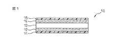
本発明の好適な実施形態につき、図面を参照しながら説明するが、本発明はそれに限定されるものではない。図1は本発明の視野角制御装置の1態様の断面図であり、図2は本発明の視野角制御装置の分解模式図である。図1及び2において、視野角制御装置10は、第一の偏光板11、第一の液晶セル12、介在層13、第二の液晶セル14及び第二の偏光板15の順に配置されている。なお、作用原理を説明するために、液晶セルはツイストネマチック型(TN)液晶を用いたセルとする。また、図3は第一の液晶セル12及び第二の液晶セル14として使用することができる液晶セル(12,14)の断面図を示している。液晶セル(12,14)は液晶層16が2枚のガラス基板などの光学的に透明な支持体17及び17’の間に配置されており、これらの支持体17及び17’にはそれぞれ電極18及び18’が配置されており、電極間に課される電圧によって、複数の領域ごとに液晶の配向が制御される。例えば、一方の支持体17の内面には、複数のストライプ状の電極18が配置されており、他方の支持体17’の内面には上記電極18と直交するように複数のストライプ状の電極18’が配置されており、課される電圧によって領域ごとに液晶層16の配向が制御される。或いは、一方の支持体17の電極18はエレメント電極であり、他方の支持体17’の電極18’は共通電極であってもよい。なお、電極にはITO(インジウムスズオキサイド)などの透明電極が用いられるべきである。 Preferred embodiments of the present invention will be described with reference to the drawings, but the present invention is not limited thereto. FIG. 1 is a cross-sectional view of one embodiment of the viewing angle control device of the present invention, and FIG. 2 is an exploded schematic view of the viewing angle control device of the present invention. 1 and 2, the viewing
図2を参照して、まず、光源からの円偏光の光は第一の偏光板11を通過するときに直線偏光になる。この直線偏光の入射光は液晶セル12に電圧を印加しない場合(オフ状態)ではツイストネマチック型液晶層16によって偏光方向が90°回転される。一方、この直線偏光の入射光は液晶セル12に電圧を印加している場合(オン状態)ではツイストネマチック型液晶層16によって偏光方向を変えずに出射される。第一の液晶セル12からの直線偏光の出射光は介在層13を通って第二の液晶セル14に入る。この直線偏光の入射光は、上記と同様に、液晶セル14に電圧を印加しない場合(オフ状態)ではツイストネマチック型液晶層16によって偏光方向が90°回転され、一方、この直線偏光の入射光は液晶セル14に電圧を印加している場合(オン状態)ではツイストネマチック型液晶層16によって偏光方向を変えずに出射される。第二の液晶セル14を出た光は第二の偏光板15に入る。ここで、第二の偏光板15の偏光方向が第一の偏光板11の偏光方向と同一の方向になるように配置されている。第二の液晶セル14を出た直線偏光の光の偏光方向が第二の偏光板15の偏光方向と一致する場合には光は透過する。一方、それらが直交する場合には光は透過しない。 With reference to FIG. 2, first, circularly polarized light from the light source becomes linearly polarized light when passing through the first polarizing
上記の構成では、第一の液晶セル12と第二の液晶セル14の両方が「オン状態」である場合には、液晶セルにおいて、偏光方向が変化しないので、第一の偏光板から出てくる光の偏光方向と、第二の偏光板に入る光の偏光方向が一致しており、光は透過する。また、第一の液晶セル12と第二の液晶セル14の両方が「オフ状態」である場合には、2つの液晶セルにおいて、偏光方向が90°ずつ回転して、180°回転するので、第一の偏光板から出てくる光の偏光方向と、第二の偏光板に入る光の偏光方向が一致しており、光は透過する。一方、第一の液晶セル12と第二の液晶セル14の一方が「オフ状態」で、他方が「オン状態」である場合には、偏光方向が90°だけ回転するので、第二の偏光板に入る光の偏光方向は第二の偏光板の偏光方向と直交する関係になり、光は遮断される。 In the above configuration, when both the first
本発明の視野角制御装置では、上記の原理に基づいて、第一の液晶層の配向と、第二の液晶の配向を制御することで視野角を制御することができる。本発明では、視野角を種々の範囲に設定して制御することができかつ視野角外から見たときに画像を完全に遮断することができる。 In the viewing angle control device of the present invention, the viewing angle can be controlled by controlling the orientation of the first liquid crystal layer and the orientation of the second liquid crystal based on the above principle. In the present invention, the viewing angle can be set and controlled in various ranges, and the image can be completely blocked when viewed from outside the viewing angle.
図4は視野角制御装置の種々の運転モードを示している。図4(a)は第一の液晶セル12及び第二の液晶セル14の全てのエレメント領域において、電圧が課されていない状態(オフ状態)である。この場合には、図4(a)に示すように、偏光板11を通過した直線偏光の入射光は、第一の液晶セル12に対していかなる角度で入射しても、第一の液晶12及び第二の液晶14をそれぞれオフ状態で1回ずつ、計2回通過する。このため、入射光の直線偏光は2つの液晶セルを通過する際に180°回転して、入射光と同一の直線偏光となる。したがって、第一の偏光板11の偏光方向と第二の偏光板15の偏光方向が同一であれば、いかなる角度で光が入射しても光は透過する(光透過モード)。図4(b)は第一の液晶セル12及び第二の液晶セル14の全てのエレメント領域において、電圧が課されている状態(オン状態)である。この場合には、図4(b)に示すように、偏光板11を通過した直線偏光の入射光は、液晶セル12に対していかなる角度で入射しても、第一の液晶12及び第二の液晶14をそれぞれオン状態で1回ずつ、計2回通過する。このため、入射光の直線偏光は2つの液晶セルを通過する際に回転せず、入射光と同一の直線偏光となる。したがって、第一の偏光板11の偏光方向と第二の偏光板15の偏光方向が同一であれば、いかなる角度で光が入射しても光は透過する(光透過モード)。このため、図4(a)及び(b)の場合には、視野角制御装置を通過する光を遮断することがないので、ディスプレイ装置(図示せず)からの画像情報を高視野角で視認することができる(高視野角モード又は光透過モード)。 FIG. 4 shows various operation modes of the viewing angle control device. FIG. 4A shows a state in which no voltage is applied (off state) in all element regions of the first
一方、図4(c)は、第一の液晶セル12及び第二の液晶セル14の一方の全てのエレメント領域において、電圧が課されている状態(オン状態)(本図では第一の液晶セル12)であり、他方の全てのエレメント領域において、電圧が課されていない状態(オフ状態)(本図では第二の液晶セル14)である場合を示している。このような場合には、第一の液晶セル12に対していかなる角度で入射しても、オフ状態で1回通過することになる。このため、入射光の直線偏光は2つの液晶セルを通過する際に90°回転して、入射光の偏光に対して直交した直線偏光となる。したがって、第一の偏光板11の偏光方向と第二の偏光板15の偏光方向が同一であれば、いかなる角度で光が入射しても光は透過せずに遮断される(光不透過モード)。 On the other hand, FIG. 4C shows a state in which a voltage is applied (on state) in all the element regions of one of the first
さらに、図4(d)において、第一の液晶セル12及び第二の液晶セル14の各々において、オン状態の領域と、オフ状態の領域を交互に形成すると、上記と同様の理由から、実線の入射角の光は透過するが、点線の入射角の光は遮断される。このように、視野角は角度θとなり、それより広い角度ではディスプレイからの画像情報を視認できない(視野角制限モード:中視野角)。さらに、図4(e)に示すように、第一の液晶セルにおいて、オン状態の領域と、オフ状態の領域の間隔を狭くすると、視野角はさらに狭いθ’となり、それより広い角度からはディスプレイからの画像情報を視認できない(視野角制限モード:狭視野角)。但し、これらの視野角制限モードにおいて、さらに広い角度では、第1の液晶セル及び第2の液晶セルの両方がオン状態または両方がオフ状態で光が通過することがある。この場合には、再び光が透過されてしまう。θまたはθ’よりも広い角度で全く視認できないようにするには、各エレメント電極の幅などの寸法と、介在層の光学距離などを最適な値とする必要がある。 Further, in FIG. 4D, when the on-state region and the off-state region are alternately formed in each of the first
一方、図4(f)に示すように、視野角制御装置10の正面から見て、第一の液晶セル12と、第二の液晶セル14との対応する位置において、一方がオン状態で、他方がオフ状態となるようにすると、装置正面からは視認することができず、斜めからの角度のみに視野角を設けることも可能である(正面不透過モード)。 On the other hand, as shown in FIG. 4 (f), when viewed from the front of the viewing
本発明の視野角制御装置は、上記のとおり、電気的に視野角を制御することができる。このため、1つの装置で、所望の視野角の範囲を容易に得ることができる。 The viewing angle control device of the present invention can electrically control the viewing angle as described above. For this reason, the range of a desired viewing angle can be easily obtained with one apparatus.
以上、本発明の視野角制御装置を原理に基づいて詳細に説明してきた。本発明の装置では、第一の偏光板及び第二の偏光板は、液晶ディスプレイパネルに使用されているような、通常の偏光板を使用することができる。また、第一の液晶セル及び第二の液晶セルとしては、液晶層の液晶の配向方向を制御することができる限り、限定されることなく、液晶ディスプレイパネルに使用されているような通常の液晶セルが使用できる。さらに、介在層は樹脂、ガラス、空気及び真空などの光学的に透明な層であればよい。なお、上記の議論から明らかなように、制御可能な視野角の範囲は液晶セルの配向を制御するための各エレメント電極の幅などの寸法と、介在層の厚さ方向の光学距離によって決まる。このため、薄型で硬い制御装置を得るためには屈折率の大きいガラスを用いることが考えられる。一方、ある程度の強度と可撓性が求められる場合には樹脂を用いることができる。 The viewing angle control device of the present invention has been described in detail based on the principle. In the apparatus of the present invention, the first polarizing plate and the second polarizing plate can be ordinary polarizing plates such as those used in liquid crystal display panels. In addition, the first liquid crystal cell and the second liquid crystal cell are not limited as long as the liquid crystal alignment direction of the liquid crystal layer can be controlled, and the normal liquid crystal used in the liquid crystal display panel is used. The cell can be used. Further, the intervening layer may be an optically transparent layer such as resin, glass, air, and vacuum. As can be seen from the above discussion, the controllable viewing angle range is determined by dimensions such as the width of each element electrode for controlling the alignment of the liquid crystal cell and the optical distance in the thickness direction of the intervening layer. For this reason, in order to obtain a thin and hard control device, it is conceivable to use a glass having a large refractive index. On the other hand, a resin can be used when a certain degree of strength and flexibility are required.
本発明の視野角制御装置は第一の偏光板、第一の液晶セル、介在層、第二の液晶セル、及び第二の偏光板の順に積層することで製造されうる。なお、介在層が空気又は真空である場合には、第一の液晶セルと第二の液晶セルとの間の周縁に樹脂或いはガラスなどのサポート材を配置して一定距離の介在層を形成することが考えられる。また、介在層には透明微小球体からなるスペーサーを若干量配置することで、介在層の距離を一定に保つことも考えられる。 The viewing angle control device of the present invention can be manufactured by laminating the first polarizing plate, the first liquid crystal cell, the intervening layer, the second liquid crystal cell, and the second polarizing plate in this order. When the intervening layer is air or vacuum, a support material such as resin or glass is disposed on the periphery between the first liquid crystal cell and the second liquid crystal cell to form an intervening layer at a certain distance. It is possible. It is also conceivable to keep a certain distance between the intervening layers by arranging a slight amount of spacers made of transparent microspheres in the intervening layer.
本発明の視野角制御装置は、1つの実施形態としてディスプレイ装置の表示面に配置される。プライバシー保護のために他人から覗かれないようにするには、上記の視野角制限モードにすることができる。一方、複数の人が見ることができるようにするためには、高視野角モードに変更することができる。例えば、オートマチックテラーマシーン(ATM)に設置されているディスプレイ装置では、普段は視野角を広くして宣伝効果を狙い、一方、顧客による暗証番号や入出金金額の入力などを行なう場合には視野角を制限するように制御することができる。なお、ディスプレイ装置が液晶パネルディスプレイである場合には、その表示面には、通常、偏光板が配置されている。このため、ディスプレイ装置の偏光板(ディスプレイ装置の前面偏光板)を本発明の視野角制御装置の第一の偏光板(後面偏光板)とみなすことができる。 The viewing angle control apparatus of this invention is arrange | positioned on the display surface of a display apparatus as one embodiment. In order to prevent others from peeping for privacy protection, the viewing angle restriction mode can be set. On the other hand, in order to allow a plurality of people to see, the mode can be changed to the high viewing angle mode. For example, in a display device installed in an automatic teller machine (ATM), the viewing angle is usually widened to aim at advertising effects, while the customer is required to enter a PIN or deposit / withdrawal amount. Can be controlled to limit. When the display device is a liquid crystal panel display, a polarizing plate is usually arranged on the display surface. For this reason, the polarizing plate of the display device (front polarizing plate of the display device) can be regarded as the first polarizing plate (rear polarizing plate) of the viewing angle control device of the present invention.
本発明の視野角制御装置は目隠し用建材として使用されることもできる。具体的には、窓、内装部材が考えられる。上記の光透過モードにすれば、通常の窓ガラスのように使用でき、光不透過モードにすれば、ブラインドとして機能する。 The viewing angle control device of the present invention can also be used as a blindfold building material. Specifically, windows and interior members can be considered. If it is set to the above-mentioned light transmission mode, it can be used like a normal window glass, and if it is set to the light non-transmission mode, it functions as a blind.
第一の偏光板及び第二の偏光板として、ある直線偏光のみを透過する偏光板HLC2−5618S(サンリッツ製粘着剤付偏光板)を用い、第一の液晶セル及び第二の液晶セルとして液晶ディスプレイパネル用液晶セルPalm V(3com社製)を用い、第一の偏光板、第一の液晶セル、第二の液晶セル及び第二の偏光板の順に並べて、本発明の視野角制御装置を形成した。なお、偏光板の厚さは約200μm(偏光フィルムと粘着剤)であり、液晶セルの厚さは約1.1mm(ガラス支持体を含む)であり、第一の液晶セルと第二の液晶セルの間の介在層は空気であり、その間の距離を約10mmとした。また、液晶セルの画素数は160×160(有効表示面積は約54.5mm×約54.5mm)である。第一の液晶セル及び第二の液晶セルに電圧印加して、上記の図4に示されたとおりに、それぞれ液晶の配向を制御すると、高視野角モード(又は光透過モード)、光不透過モード、視野角制限モード(例えば、θ=120度、すなわち、正面から約60度で不透過となる)、正面不透過モードで制御できることがわかった。 As the first polarizing plate and the second polarizing plate, a polarizing plate HLC2-5618S (a polarizing plate with adhesive made by Sanritz) that transmits only certain linearly polarized light is used, and liquid crystal is used as the first liquid crystal cell and the second liquid crystal cell. Using the liquid crystal cell Palm V for display panel (manufactured by 3com), the first polarizing plate, the first liquid crystal cell, the second liquid crystal cell, and the second polarizing plate are arranged in this order, and the viewing angle control device of the present invention is arranged. Formed. The polarizing plate has a thickness of about 200 μm (polarizing film and adhesive), the liquid crystal cell has a thickness of about 1.1 mm (including a glass support), and the first liquid crystal cell and the second liquid crystal The intervening layer between the cells was air, and the distance between them was about 10 mm. The number of pixels of the liquid crystal cell is 160 × 160 (effective display area is about 54.5 mm × about 54.5 mm). When a voltage is applied to the first liquid crystal cell and the second liquid crystal cell and the orientation of the liquid crystal is controlled as shown in FIG. 4, the high viewing angle mode (or light transmission mode) and light non-transmission are obtained. It was found that the control can be performed in the mode, the viewing angle limiting mode (for example, θ = 120 degrees, that is, the light is not transmitted at about 60 degrees from the front), and the front opaque mode.
10…視野角制御装置
11…第一の偏光板
12…第一の液晶セル
13…介在層
14…第二の液晶セル
15…第二の偏光板
16…液晶層
17,17’…支持体
18,18’…電極DESCRIPTION OF
Claims (5)
Translated fromJapanesePriority Applications (1)
| Application Number | Priority Date | Filing Date | Title |
|---|---|---|---|
| JP2004226651AJP2006047550A (en) | 2004-08-03 | 2004-08-03 | Viewing angle control device |
Applications Claiming Priority (1)
| Application Number | Priority Date | Filing Date | Title |
|---|---|---|---|
| JP2004226651AJP2006047550A (en) | 2004-08-03 | 2004-08-03 | Viewing angle control device |
Publications (1)
| Publication Number | Publication Date |
|---|---|
| JP2006047550Atrue JP2006047550A (en) | 2006-02-16 |
Family
ID=36026191
Family Applications (1)
| Application Number | Title | Priority Date | Filing Date |
|---|---|---|---|
| JP2004226651APendingJP2006047550A (en) | 2004-08-03 | 2004-08-03 | Viewing angle control device |
Country Status (1)
| Country | Link |
|---|---|
| JP (1) | JP2006047550A (en) |
Cited By (2)
| Publication number | Priority date | Publication date | Assignee | Title |
|---|---|---|---|---|
| WO2008114678A1 (en)* | 2007-03-16 | 2008-09-25 | Sharp Kabushiki Kaisha | Viewing angle control device and display provided with the same |
| KR20170068642A (en)* | 2015-12-09 | 2017-06-20 | 엘지디스플레이 주식회사 | Display panel and display device comprising the same |
Citations (3)
| Publication number | Priority date | Publication date | Assignee | Title |
|---|---|---|---|---|
| JPH06118436A (en)* | 1992-10-06 | 1994-04-28 | Olympus Optical Co Ltd | Optical device using liquid crystal shutter |
| JPH09105958A (en)* | 1995-10-13 | 1997-04-22 | Sharp Corp | Variable viewing angle element and variable viewing angle liquid crystal display device using the same |
| JPH117045A (en)* | 1997-06-16 | 1999-01-12 | Nec Corp | Active matrix liquid crystal display device |
- 2004
- 2004-08-03JPJP2004226651Apatent/JP2006047550A/enactivePending
Patent Citations (3)
| Publication number | Priority date | Publication date | Assignee | Title |
|---|---|---|---|---|
| JPH06118436A (en)* | 1992-10-06 | 1994-04-28 | Olympus Optical Co Ltd | Optical device using liquid crystal shutter |
| JPH09105958A (en)* | 1995-10-13 | 1997-04-22 | Sharp Corp | Variable viewing angle element and variable viewing angle liquid crystal display device using the same |
| JPH117045A (en)* | 1997-06-16 | 1999-01-12 | Nec Corp | Active matrix liquid crystal display device |
Cited By (5)
| Publication number | Priority date | Publication date | Assignee | Title |
|---|---|---|---|---|
| WO2008114678A1 (en)* | 2007-03-16 | 2008-09-25 | Sharp Kabushiki Kaisha | Viewing angle control device and display provided with the same |
| CN101632039B (en)* | 2007-03-16 | 2011-09-07 | 夏普株式会社 | Angle of view control device and display with the same |
| US8199139B2 (en) | 2007-03-16 | 2012-06-12 | Sharp Kabushiki Kaisha | Viewing angle control device and display provided with the same |
| KR20170068642A (en)* | 2015-12-09 | 2017-06-20 | 엘지디스플레이 주식회사 | Display panel and display device comprising the same |
| KR102394392B1 (en)* | 2015-12-09 | 2022-05-04 | 엘지디스플레이 주식회사 | Display panel and display device comprising the same |
Similar Documents
| Publication | Publication Date | Title |
|---|---|---|
| JP4704349B2 (en) | Display device, viewing angle control device, and electronic device | |
| EP4443225A2 (en) | Optical stack for switchable directional display | |
| JP4750136B2 (en) | display | |
| KR100742052B1 (en) | Display | |
| JP4494410B2 (en) | Display device, viewing angle control device, and electronic device | |
| US7760301B2 (en) | Liquid crystal device and electronic apparatus | |
| GB2428100A (en) | Display device and optical device | |
| JP5093710B2 (en) | Display device, terminal device, light source device, and optical member | |
| JPWO2009011199A1 (en) | Display and viewing angle control element used therefor | |
| JP2009020293A (en) | Display and viewing angle control device used therefor | |
| WO2008001896A1 (en) | Display and field-of-view angle control device used for the same | |
| US7990483B2 (en) | Stereoscopic image display apparatus | |
| JP6887525B2 (en) | Display device | |
| JP2008096458A (en) | Display and viewing angle control device used therefor | |
| WO2016035624A1 (en) | Mirror display having touch panel | |
| JP2008064790A (en) | Display and viewing angle control device used therefor | |
| US20060203165A1 (en) | Display apparatus and viewing angle controlling unit | |
| KR20140013223A (en) | Liquid crystal display device | |
| JP4774957B2 (en) | Liquid crystal display | |
| KR100998695B1 (en) | Display device with adjustable viewing angle | |
| JP2006047550A (en) | Viewing angle control device | |
| JP2008299280A (en) | Display and viewing angle control device used therefor | |
| KR101274027B1 (en) | Display panel and display apparatus having the same | |
| JPWO2018116895A1 (en) | LCD panel | |
| JP2006113479A (en) | Liquid crystal display device |
Legal Events
| Date | Code | Title | Description |
|---|---|---|---|
| A621 | Written request for application examination | Free format text:JAPANESE INTERMEDIATE CODE: A621 Effective date:20070727 | |
| A131 | Notification of reasons for refusal | Free format text:JAPANESE INTERMEDIATE CODE: A131 Effective date:20100615 | |
| A02 | Decision of refusal | Free format text:JAPANESE INTERMEDIATE CODE: A02 Effective date:20101116 |