JP2006042988A - Fixed frame of daitama ball lending machine - Google Patents
Fixed frame of daitama ball lending machineDownload PDFInfo
- Publication number
- JP2006042988A JP2006042988AJP2004225788AJP2004225788AJP2006042988AJP 2006042988 AJP2006042988 AJP 2006042988AJP 2004225788 AJP2004225788 AJP 2004225788AJP 2004225788 AJP2004225788 AJP 2004225788AJP 2006042988 AJP2006042988 AJP 2006042988A
- Authority
- JP
- Japan
- Prior art keywords
- ball
- lending machine
- ball lending
- game
- fixed frame
- Prior art date
- Legal status (The legal status is an assumption and is not a legal conclusion. Google has not performed a legal analysis and makes no representation as to the accuracy of the status listed.)
- Pending
Links
- NJPPVKZQTLUDBO-UHFFFAOYSA-NnovaluronChemical compoundC1=C(Cl)C(OC(F)(F)C(OC(F)(F)F)F)=CC=C1NC(=O)NC(=O)C1=C(F)C=CC=C1FNJPPVKZQTLUDBO-UHFFFAOYSA-N0.000description4
- 238000003780insertionMethods0.000description2
- 230000037431insertionEffects0.000description2
- 238000007689inspectionMethods0.000description1
- 238000009434installationMethods0.000description1
- 239000004973liquid crystal related substanceSubstances0.000description1
Images

Landscapes
- Pinball Game Machines (AREA)
Abstract
Translated fromJapaneseDescription
Translated fromJapanese本発明は、隣り合った遊技台間の奥部に固定されるフレーム本体を備え、このフレーム本体に対して、台間玉貸機が前方から挿入されて取り付けられる構成とされた台間玉貸機の固定フレームに関する。 The present invention includes a frame main body that is fixed in the back part between adjacent game tables, and a stand ball lending machine configured to be inserted and attached to the frame main body from the front. It relates to the fixed frame of the machine.
従来より、パチンコホールにおいては、隣り合った遊技台間に位置させて台間玉貸機が設けられている。この台間玉貸機の取付構造としては、次のような構造となっている。すなわち、台間玉貸機の固定フレームは、フレーム本体が、前部が開口したほぼコ字形をなしていて、隣り合った遊技台間の奥部に固定される。そして、台間玉貸機は、固定フレームのフレーム本体に対して前方から挿入されて取り付けられる。フレーム本体の上部には、玉供給用の玉供給ホースが接続されるようになっていて、遊技玉(パチンコ玉)が玉供給ホースから台間玉貸機に供給されるようになっている(例えば、特許文献1参照)。
ところで、台間玉貸機を点検・修理したり、交換したりするために前方へ引き出した際に、玉供給ホースから遊技玉が遊技台間にこぼれ落ちることがある。遊技玉がこぼれ落ちたままの状態で、台間玉貸機を遊技台間の固定フレームに挿入しようとすると、こぼれ落ちた遊技玉が邪魔になり、固定フレームに取り付けることができない。このとき、遊技台間に落ちた遊技玉は作業者が手を挿入して取り除くことになるが、遊技台間の隙間は狭く、取り除き難いものであった。 By the way, when the pedestal ball lending machine is pulled forward for inspection, repair, or exchange, game balls may spill between the game tables from the ball supply hose. If an attempt is made to insert a machine ball lending machine into a fixed frame between game machines with the game ball still spilled, the spilled game ball gets in the way and cannot be attached to the fixed frame. At this time, the game balls dropped between the game tables are removed by the operator by inserting a hand, but the gap between the game tables is narrow and difficult to remove.
本発明は、上記した問題点を解決するためになされたもので、遊技台間に遊技玉が落ちていたとしても、その遊技玉を作業者が手で取り除くことなく、台間玉貸機を遊技台間に挿入して取り付けることができる台間玉貸機の固定フレームを提供することを目的とする。 The present invention has been made to solve the above-described problems, and even if a game ball has fallen between game machines, an operator can remove the game ball without removing it by hand. It is an object of the present invention to provide a fixed frame for a stand lending machine that can be inserted and attached between game machines.
上記した目的を達成するために、本発明は、隣り合った遊技台間に固定されるフレーム本体を備え、このフレーム本体に対して、台間玉貸機が前方から挿入されて取り付けられる構成とされた台間玉貸機の固定フレームにおいて、前記フレーム本体の後部の下部に、玉排出孔を設けたことを特徴とする。 In order to achieve the above-described object, the present invention includes a frame main body fixed between adjacent game machines, and a structure in which a ball lending machine is inserted and attached to the frame main body from the front. The fixed frame of the inter-bed ball lending machine is characterized in that a ball discharge hole is provided in a lower portion of the rear portion of the frame main body.
上記した手段によれば、台間玉貸機を固定フレームのフレーム本体に対して引き出した際に遊技台間に遊技玉が落ち、それがそこに残っていたとしても、台間玉貸機をフレーム本体に対して挿入すると、落ちていた遊技玉は台間玉貸機に押されて、フレーム本体の玉排出孔から排出されるようになる。したがって、遊技台間に遊技玉が落ちていたとしても、遊技玉を作業者が手で取り除くことなく、台間玉貸機を遊技台間に挿入して取り付けることができる。 According to the above-described means, even if the game ball falls between the game tables when the table ball lending machine is pulled out with respect to the frame body of the fixed frame, When inserted into the frame main body, the game balls that have fallen are pushed by the interstitial ball lending machine and discharged from the ball discharge holes of the frame main body. Therefore, even if the game balls are dropped between the game machines, the machine ball lending machine can be inserted and attached between the game machines without the operator removing the game balls by hand.
以下、本発明の一実施形態について図面を参照して説明する。
図1において、台間玉貸機1は、隣り合った図示しない遊技台(パチンコ台)間に設置されるもので、薄型の矩形状のケース2を備えている。このケース2の前面部には、硬貨投入口3、液晶表示器4、玉案内用ノズル5、カード挿入口6等が設けられている。また、ケース2の上面部の後部には、玉受入れ口7が設けられている。なお、ケース2の後面部には、図示はしないが、後述する係合部16が係合する被係合部が設けられている。Hereinafter, an embodiment of the present invention will be described with reference to the drawings.
In FIG. 1, an inter-ball ball lending machine 1 is installed between adjacent game machines (pachinko machines) (not shown), and includes a thin
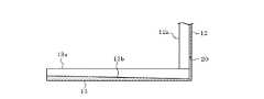
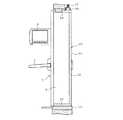
この台間玉貸機1を取り付けるための固定フレーム10のフレーム本体11は、上下方向に延びる縦片部12と、この縦片部12の下端部に前方へ向けて突設された底片部13(フレーム本体11の底部に相当)と、縦片部12の上端部に前方へ向けて突設された天井片部14とを有し、全体として前部が開口したコ字形をなしている。このフレーム本体10は、隣り合った遊技台(図示せず)間に位置させて、図3に示すように、縦片部12を奥側(図3の右側)にした状態でパチンコホールの島の基台15に固定状態に設けられる。このフレーム本体10における縦片部12の左右両側部には前方へ向けて突出する突片12aが設けられ、底片部13の左右両側部にも上方へ向けて突出する突片13aが設けられ、また、天井片部14の左右両側部にも下方へ向けて突出する突片14aが設けられている。 The frame
縦片部12の上下方向の中間部には、前方に向けて突出する係合部16が設けられている。天井片部14の後部には、玉供給ホース17と接続可能なホース接続部18が設けられている。そして、本体ケース11の後部である縦片部12の下部には、矩形状をなす玉排出孔20が設けられている。この玉排出孔20は、遊技玉(パチンコ玉)21が通過可能な大きさに形成されている。底片部13の上面13bは、図2に示すように前部から後部の玉排出孔20に向かって下降傾斜するゆるやかな斜面として形成されている。 An
上記構成において、台間玉貸機1を、遊技台間に設けられた固定フレーム10に取り付ける場合には、台間玉貸機1のケース2を、固定フレーム10における底片部13と天井片部14との間に前方から挿入する。このとき、底片部13および天井部14の前後方向に延びる左右の各突片13a,14aにより、そのケース2の挿入がガイドされる。そして、台間玉貸機1のケース2をフレーム本体11の奥まで挿入することに伴い、固定フレーム10の係合部16がケース2の被係合部に係合する。これにより、台間玉貸機1が固定フレーム10に取り付けられた状態となる。この状態で、ケース2の上面部の玉受入れ口7が玉供給ホース17と連通する状態となり、遊技玉が玉供給ホース17から台間玉貸機1へ供給可能な状態となる。 In the above configuration, when attaching the ball rental machine 1 to the
一方、台間玉貸機1を点検或いは修理するために取り外す場合には、上記係合部16による係合を解除した状態で、台間玉貸機1を前方へ引き出す。このとき、台間玉貸機1の玉受入れ口7が、玉供給ホース17の下端部からずれることに伴い、玉供給ホース17の下端部から遊技玉21がこぼれて、遊技台間のケース本体11内に落ちることがある。このとき、底片部13の上面13bは玉排出孔20に向かって下降傾斜するゆるやかな斜面となっているので、上面13b上の遊技玉21は玉排出孔20から排出され易くなる。 On the other hand, when removing the pedestal ball lending machine 1 for checking or repairing, the pedestal ball lending machine 1 is pulled forward with the
また、上面13b上に遊技玉21がある状態であっても、台間玉貸機1を取り付けるべく、固定フレーム10の底片部13と天井片部14との間に前方から挿入すると、遊技玉21は台間玉貸機1のケース2に押されて玉排出孔20から排出されるようになる。したがって、遊技台間に遊技玉21が落ちていたとしても、遊技玉21を作業者が手で取り除くことなく、台間玉貸機1を遊技台間に挿入して取り付けることができる。 Further, even when the
本発明は、上記した実施形態にのみ限定されるものではなく、次のように変形または拡張できる。
玉排出孔20は、フレーム本体11の縦片部12と底片部13の両方に跨るように設けても良く、また、底片部13の後部のみに設けることもできる。The present invention is not limited to the above-described embodiment, and can be modified or expanded as follows.
The
図面中、1は台間玉貸機、10は固定フレーム、11はフレーム本体、13は底片部(底部)、13bは上面、16は係合部、17は玉供給ホース、20は玉排出孔、21は遊技玉を示す。
In the drawings, 1 is an inter-ball ball lending machine, 10 is a fixed frame, 11 is a frame body, 13 is a bottom piece (bottom), 13b is an upper surface, 16 is an engaging portion, 17 is a ball supply hose, and 20 is a ball discharge hole. , 21 indicates a game ball.
Claims (2)
Translated fromJapaneseThe fixed frame of the inter-lens ball lending machine according to claim 1, wherein an upper surface of a bottom portion of the frame main body is inclined downward toward the ball discharge hole.
Priority Applications (1)
| Application Number | Priority Date | Filing Date | Title |
|---|---|---|---|
| JP2004225788AJP2006042988A (en) | 2004-08-02 | 2004-08-02 | Fixed frame of daitama ball lending machine |
Applications Claiming Priority (1)
| Application Number | Priority Date | Filing Date | Title |
|---|---|---|---|
| JP2004225788AJP2006042988A (en) | 2004-08-02 | 2004-08-02 | Fixed frame of daitama ball lending machine |
Publications (1)
| Publication Number | Publication Date |
|---|---|
| JP2006042988Atrue JP2006042988A (en) | 2006-02-16 |
Family
ID=36022205
Family Applications (1)
| Application Number | Title | Priority Date | Filing Date |
|---|---|---|---|
| JP2004225788APendingJP2006042988A (en) | 2004-08-02 | 2004-08-02 | Fixed frame of daitama ball lending machine |
Country Status (1)
| Country | Link |
|---|---|
| JP (1) | JP2006042988A (en) |
Cited By (1)
| Publication number | Priority date | Publication date | Assignee | Title |
|---|---|---|---|---|
| JP6406727B1 (en)* | 2017-06-15 | 2018-10-17 | ハイライツ・エンタテインメント株式会社 | Taima ball lending machine |
- 2004
- 2004-08-02JPJP2004225788Apatent/JP2006042988A/enactivePending
Cited By (1)
| Publication number | Priority date | Publication date | Assignee | Title |
|---|---|---|---|---|
| JP6406727B1 (en)* | 2017-06-15 | 2018-10-17 | ハイライツ・エンタテインメント株式会社 | Taima ball lending machine |
Similar Documents
| Publication | Publication Date | Title |
|---|---|---|
| WO2007106166A8 (en) | Card shoe for holding playing cards | |
| JP2013099461A (en) | Game machine | |
| JP2003250960A5 (en) | ||
| JP2006042988A (en) | Fixed frame of daitama ball lending machine | |
| JP2005218792A (en) | Pachinko machine | |
| JP2014100166A (en) | Game machine | |
| JP2006280971A (en) | Attachment structure for game board of pachinko game machine | |
| JP2008073293A (en) | Game machine | |
| JP5242298B2 (en) | Game machine | |
| JP3094385B2 (en) | Pachinko machine circuit box mounting structure | |
| JP3550329B2 (en) | Game member mounting structure for pachinko machines | |
| JP6097530B2 (en) | Game machine | |
| JP5435356B2 (en) | Pachinko machine | |
| JP2002126227A (en) | Gaming machine winning device and gaming machine | |
| JP4723537B2 (en) | Bullet ball machine | |
| JP4014664B2 (en) | Bullet ball machine | |
| JP3975413B2 (en) | Back set member for pachinko machines | |
| JP2005224533A (en) | Mounting structure of relay board in game machine | |
| JP5722109B2 (en) | Dispenser | |
| JP5090675B2 (en) | Earth structure and gaming machine | |
| JP5837334B2 (en) | Structure for preventing compatibility of gaming boards in gaming machines | |
| JP2542550B2 (en) | Display device for front frame of pachinko machine | |
| JP4213674B2 (en) | Game machine | |
| JP3096244U (en) | Main board holder mounting structure | |
| JP2596896B2 (en) | Gaming machine |