JP2006040808A - Metal dome type switch structure with ventilation groove - Google Patents
Metal dome type switch structure with ventilation grooveDownload PDFInfo
- Publication number
- JP2006040808A JP2006040808AJP2004222117AJP2004222117AJP2006040808AJP 2006040808 AJP2006040808 AJP 2006040808AJP 2004222117 AJP2004222117 AJP 2004222117AJP 2004222117 AJP2004222117 AJP 2004222117AJP 2006040808 AJP2006040808 AJP 2006040808A
- Authority
- JP
- Japan
- Prior art keywords
- metal dome
- switch
- sheet
- ventilation groove
- printed circuit
- Prior art date
- Legal status (The legal status is an assumption and is not a legal conclusion. Google has not performed a legal analysis and makes no representation as to the accuracy of the status listed.)
- Pending
Links
Images


Landscapes
- Push-Button Switches (AREA)
Abstract
Translated fromJapaneseDescription
Translated fromJapanese本発明は、携帯電話やデジタルカメラ、PDAなどのキースイッチとして用いられるメタルドーム型スイッチの構造に関し、スイッチのクリック感の低下を防止するための通気溝を設けたメタルドーム型スイッチの構造に関する。 The present invention relates to a structure of a metal dome type switch used as a key switch for a mobile phone, a digital camera, a PDA, etc., and relates to a structure of a metal dome type switch provided with a ventilation groove for preventing a click feeling of the switch from being lowered.
携帯電話やデジタルカメラ、PDAなどのキースイッチとして、金属を皿状に変形させた弾性変形可能なドーム型可動接点(以下、メタルドームという)を使用したメタルドーム型スイッチが採用されている。
メタルドーム型スイッチは、第1固定接点と第2固定接点とからなるスイッチ接点を備えるプリント基板と、前記スイッチ接点に搭載されるメタルドームと、プリント基板にメタルドームを固定するための押さえシートとから構成される。
スイッチオフ状態の場合、プリント基板に固定されたメタルドームは、その周縁が第1固定接点に接地し、第1固定接点のみにメタルドームが接する。
スイッチをクリックしてスイッチオン状態にした場合、プリント基板に固定したメタルドームが弾性変形し、メタルドームの周縁が第1固定接点に接地するとともに、メタルドームの中央部分が第2固定接点に接地し、第1固定接点と第2固定接点はメタルドームを介して導通する。
なお、プリント基板にメタルドームを固定するための押さえシートは、ポリエステル系基材からなる粘着シートや、ポリエステル系フィルムに粘着剤を印刷した粘着シートが使用されている。また前記粘着剤としては、価格や作業性などの理由からアクリル系の粘着剤が用いられている。
そしてメタルドーム型スイッチの防水・防塵性を向上させるため、押さえシートの全面に粘着剤を塗布したものが使用されている。As a key switch for a cellular phone, a digital camera, a PDA or the like, a metal dome type switch using an elastically deformable dome type movable contact (hereinafter referred to as a metal dome) obtained by deforming metal into a dish shape is adopted.
The metal dome type switch includes a printed circuit board having a switch contact made of a first fixed contact and a second fixed contact, a metal dome mounted on the switch contact, and a pressing sheet for fixing the metal dome to the printed circuit board. Consists of
In the switch-off state, the metal dome fixed to the printed circuit board is grounded to the first fixed contact, and the metal dome contacts only the first fixed contact.
When the switch is turned on by clicking the switch, the metal dome fixed to the printed circuit board is elastically deformed, the periphery of the metal dome is grounded to the first fixed contact, and the central portion of the metal dome is grounded to the second fixed contact The first fixed contact and the second fixed contact are conducted through the metal dome.
In addition, the pressure sheet for fixing a metal dome to a printed circuit board uses the adhesive sheet which consists of a polyester-type base material, and the adhesive sheet which printed the adhesive on the polyester-type film. As the pressure-sensitive adhesive, an acrylic pressure-sensitive adhesive is used for reasons such as cost and workability.
And in order to improve the waterproof and dustproof property of a metal dome type switch, what applied the adhesive to the whole surface of the pressing sheet is used.
従来技術によれば、スイッチのクリック感の低下を防止するために、スイッチ内の空気を逃がすための通気溝(メタルドームの外周部に通気可能な溝)を設けたメタルドーム型スイッチ構造が知られている。(例えば、特許文献1を参照)
図3を参照して、従来技術による通気溝を設けたメタルドーム型スイッチの構造を説明する。
図3(a)は、従来技術によるメタルドーム型スイッチの断面図であり、図3(b)は、メタルドーム型スイッチの平面図であり、図3(c)は、メタルドーム型スイッチの作成方法を説明する図である。
従来技術によれば、通気溝103cを備える1枚の押さえシート103を用いて、スイッチ接点を備える基板101に対して、メタルドーム102を固定していた。
図3(a)に示すメタルドーム型スイッチは、第1固定接点101a及び第2固定接点101bからなるスイッチ接点を2つ備えるプリント基板101と、2つのメタルドーム102と、プリント基板101に2つのメタルドーム102を固定するための押さえシート103とから構成される。
そして、プリント基板101の2つのスイッチ接点にそれぞれメタルドーム102を搭載するとともに、メタルドーム102が搭載されたプリント基板101の上から通気溝103cを備える1枚の押さえシート103を貼り合せて、プリント基板1に対して各メタルドーム102を固定していた。
また図3(b)に示すように、プリント基板101の表面に押さえシート103を貼り合わせるときに、押さえシート103にある通気溝103cを、隣り合うスイッチ間(隣り合うメタルドーム102間)に配置することによって、スイッチ内の空気を逃がすための通気溝103cを形成していた。前記通気溝103cを設けることによって、一方のスイッチをクリックした際にスイッチ内の空気が隣のスイッチ内に流れ込み、スイッチのクリック感が損なわれるのを防止できる。
なお従来技術によれば、図3(c)に示すように、ポリエステル系フィルムからなるシート基材103aと粘着層(粘着剤)103bとからなる押さえシート103に、粘着剤を塗布されていない部分からなる通気溝103cを形成し、当該押さえシート103の粘着層103bに2つのメタルドーム102を載置することによって、2つのメタルドームが付着した押さえシートを作成した。そして、当該メタルドーム付きの押さえシートを反転し、第1固定接点101a及び第2固定接点101bからなる2つのスイッチ接点にそれぞれメタルドーム102が搭載されるように、プリント基板101の表面に押さえシート103を貼り合せ、プリント基板101にメタルドーム102を固定していた。
なお防水・防塵性を向上させるため、通気溝103cを除くシート全面に粘着剤を塗布し、当該押さえシート103を、メタルドーム102を搭載したプリント基板1の表面に貼り合せることによって、複数のメタルドーム102をプリント基板101に固定していた。
With reference to FIG. 3, the structure of a metal dome type switch provided with a vent groove according to the prior art will be described.
3A is a cross-sectional view of a conventional metal dome type switch, FIG. 3B is a plan view of the metal dome type switch, and FIG. 3C is a creation of the metal dome type switch. It is a figure explaining a method.
According to the prior art, the
The metal dome type switch shown in FIG. 3A includes a printed
Then, a
Further, as shown in FIG. 3B, when the
In addition, according to the prior art, as shown in FIG. 3 (c), a portion where the pressure-sensitive adhesive sheet is not applied to the
In order to improve the waterproof and dustproof properties, an adhesive is applied to the entire surface of the sheet except the
図3(c)に示すように、複数のメタルドーム102が付着したメタルドーム付き押さえシートをプリント基板101に貼り合せることによって、プリント基板101にメタルドーム102を固定する場合、プリント基板101に押さえシート103を貼り合せている工程で、押さえシート103からメタルドーム102が剥がれ落ちたり外れたりして、プリント基板101に固定されたメタルドーム102の位置精度が低下し、製造の際の作業性も悪かった。
また従来技術では、防水・防塵性を向上させるためにシートの全面に粘着剤を塗布した1枚の押さえシート103によって、複数のメタルドーム102をまとめて固定していたため、プリント基板101に固定した複数のメタルドーム102のうち1つのメタルドームを交換するといった修理の際、プリント基板1の表面に貼りあわされている押さえシート103を剥がした後、全てのメタルドーム102について、新たな押さえシート103を用いてプリント基板101に固定しなおさなければならなかった。As shown in FIG. 3C, when the
Further, in the prior art, a plurality of
そこで本発明は、小片シート基材と粘着層とからなる小片押さえシートを使用して、プリント基板のスイッチ接点にメタルドームを固定したメタルドーム型スイッチの構造であって、第1及び第2固定接点とからなるスイッチ接点を備えるプリント基板の表面に、スイッチ接点の配設位置に対応して形成した開口部と、前記開口部に連結する通気溝とを備える大判粘着シートを貼り合せたことによって、スイッチ内の空気を逃がすための通気溝が形成され、さらに、小片押さえシートの粘着層に1つのメタルドームを載置して作成した小片押さえシート付きメタルドームを、開口部の内側に配置されたスイッチ接点に搭載するとともに、スイッチ接点に搭載したメタルドームに付着している小片押さえシートの周縁部分を大判粘着シートの表面に貼り付けたことによって、プリント基板に対してメタルドームが固定されたものである。 Therefore, the present invention is a metal dome type switch structure in which a metal dome is fixed to a switch contact of a printed circuit board using a small sheet pressing sheet composed of a small sheet base material and an adhesive layer. By attaching a large-sized adhesive sheet having an opening formed corresponding to the arrangement position of the switch contact and a ventilation groove connected to the opening on the surface of the printed circuit board including the switch contact formed of the contact. A ventilation groove is formed to allow air inside the switch to escape, and a metal dome with a small piece holding sheet created by placing one metal dome on the adhesive layer of the small piece holding sheet is placed inside the opening. In addition to mounting on the switch contact, the peripheral part of the small piece holding sheet adhering to the metal dome mounted on the switch contact By adhered to, in which the metal dome is fixed to the printed board.
本発明による通気溝を設けたメタルドーム型スイッチ構造によれば、開口部及び通気溝を備える大判粘着シートをプリント基板の表面に貼り合せることによって、スイッチ内の空気を逃がすための通気溝を形成するとともに、小片押さえシートを使用して、各スイッチ接点に搭載されたメタルドームを一つ一つ固定した。
すなわち、小片押さえシートによって、スイッチ接点に搭載したメタルドームを個々に固定したため、メタルドームを交換するといった修理の際は、交換すべきメタルドームを固定している小片押さえシートのみを剥がせばよく、簡単に修理することができる。
また、複数のメタルドームが付着した押さえシートをプリント基板に貼り合せることによってスイッチ接点にメタルドームを固定していた従来技術に比べ、小片押さえシートの粘着層に1つのメタルドームを載置して作成した小片押さえシート付きメタルドームを使用するため、メタルドームの固定作業中に、粘着層からメタルドームが剥がれ落ちたり、外れたりする虞がなく、作業性が向上し、かつメタルドームの位置精度が向上する。
さらに、通気溝を除いて全面に粘着剤を塗布した大判粘着シートと、小片シート基材の全面に粘着剤を塗布した小片押さえシートを使用するため、防水・防塵性が損なわれることなくプリント基板にメタルドームを固定することができる。According to the metal dome type switch structure provided with a ventilation groove according to the present invention, a large-sized adhesive sheet having an opening and a ventilation groove is bonded to the surface of the printed circuit board, thereby forming a ventilation groove for releasing air in the switch. In addition, the metal domes mounted on each switch contact were fixed one by one using a small piece holding sheet.
That is, because the metal domes mounted on the switch contacts are individually fixed by the small piece pressing sheet, when repairing such as replacing the metal dome, it is only necessary to peel off only the small pressing sheet that fixes the metal dome to be replaced. Can be repaired easily.
Compared to the conventional technology in which a metal dome is fixed to a switch contact by bonding a pressing sheet with a plurality of metal domes attached to a printed circuit board, a single metal dome is placed on the adhesive layer of a small pressing sheet. Because the metal dome with small piece holding sheet created is used, there is no risk of the metal dome coming off or coming off from the adhesive layer during the metal dome fixing work, improving workability and positioning accuracy of the metal dome. Will improve.
In addition, a large-sized adhesive sheet with adhesive applied to the entire surface, excluding the ventilation grooves, and a small piece presser sheet with adhesive applied to the entire surface of the small sheet base material are used. Metal dome can be fixed to
本発明の実施例による通気溝を設けたメタルドーム型スイッチを、図1及び図2を参照して説明する。 A metal dome type switch provided with a ventilation groove according to an embodiment of the present invention will be described with reference to FIGS.
この発明によるメタルドーム型スイッチは、第1及び第2固定接点1a,1bとからなるスイッチ接点を備えるプリント基板1と、前記プリント基板1のスイッチ接点に搭載されるメタルドーム2と、スイッチ内の空気を逃がすための通気溝32を形成するための大判粘着シート3と、プリント基板1にメタルドーム2を固定するための小片押さえシート4とから構成される。
そして、スイッチ接点を備えるプリント基板1の表面に、スイッチ接点の配設位置に対応して形成した開口部31と、当該開口部31に連結する通気溝32とを備える大判粘着シート3を貼り合せることによって、スイッチ内の空気を逃がすための通気溝32を形成した。
また大判粘着シート3を貼り合せたプリント基板1に対し、開口部31の内側に配置されたスイッチ接点に搭載されたメタルドーム2を小片押さえシート4によって固定した。なお、1枚の小片押さえシート4につき、1つのメタルドーム2をプリント基板1のスイッチ接点に固定した。A metal dome type switch according to the present invention includes a printed
And the large-sized
In addition, the metal dome 2 mounted on the switch contact disposed inside the
図1(a)は、メタルドーム型スイッチの平面図を示すものであり、図1(b)は、図1(a)に示すA−A線の断面図である。
図1に示すメタルドーム型スイッチは、第1固定接点1aと第2固定接点1bとからなるスイッチ接点を5つ備えるプリント基板1に対して、小片押さえシート4を使用して、5つのメタルドーム2をそれぞれ固定したものである。
なおスイッチオフ状態の場合、プリント基板1のスイッチ接点に搭載(固定)されたメタルドーム2は、その周縁が第1固定接点1aに接地し、第1固定接点1aのみにメタルドーム2が接する。
スイッチをクリックしてスイッチオン状態にした場合、プリント基板1のスイッチ接点に搭載(固定)されたメタルドームが弾性変形し、メタルドーム2の周縁が第1固定接点1aに接地するとともに、メタルドーム2の中央部分が第2固定接点1bに接地し、第1固定接点1aと第2固定接点1bとがメタルドーム2を介して導通する。FIG. 1A shows a plan view of a metal dome type switch, and FIG. 1B is a cross-sectional view taken along line AA shown in FIG.
The metal dome type switch shown in FIG. 1 uses a small
In the switch-off state, the metal dome 2 mounted (fixed) on the switch contact of the printed
When the switch is turned on by clicking the switch, the metal dome mounted (fixed) on the switch contact of the printed
図1(a)に示すように、第1及び第2固定接点1a,1bからなるスイッチ接点を備えるプリント基板1の表面に、開口部31と通気溝32とを備える大判粘着シート3を貼り合わせることによって、スイッチ内の空気を逃がすための通気溝32を形成した。
なお大判粘着シート3の開口部31は、プリント基板1のスイッチ接点の配設位置に対応して配置され、前記開口部31に連結する通気溝32は、スイッチ接点間に配置されている。
そして大判粘着シート3を貼り合せたプリント基板1に対し、開口部31の内側に配置されたスイッチ接点(5箇所)に搭載されるメタルドーム2のそれぞれを、小片押さえシート4によって固定した。なお1つのメタルドーム2につき、1枚の小片押さえシート4を使用して、プリント基板1にメタルドーム2を固定した。As shown in FIG. 1A, a large-
The
And each of the metal dome 2 mounted in the switch contact (5 places) arrange | positioned inside the opening
さらにこの実施例では、図1(b)に示すように、プリント基板1のスイッチ接点の配設位置(5箇所)に、大判粘着シート3の開口部31(5箇所)がそれぞれ配置されるようにプリント基板1と大判粘着シート3とを貼り合せ、さらに前記開口部31に連結する通気溝32を、隣り合うスイッチ接点間に配置し、スイッチ内の空気を逃がすための通気溝32を形成した。
スイッチ内の空気を逃がすための通気溝32を各スイッチに設けることによって、1つのスイッチをクリックした際に当該スイッチ内の空気が隣のスイッチ内に流れ込み、スイッチのクリック感が損なわれるのを防止できる。Further, in this embodiment, as shown in FIG. 1B, the opening portions 31 (five places) of the large-
By providing each switch with a
通気溝32を除いてシート全面に粘着剤を塗布した大判粘着シート3を、プリント基板1の表面に貼り合せるとともに、シート全面に粘着剤を塗布した小片粘着シート4を、開口部31の内側に配置されるスイッチ接点に搭載されるメタルドーム2の上から貼り付けて、プリント基板1の各スイッチ接点に対してそれぞれメタルドーム2を固定したこの発明によるメタルドーム型スイッチでは、JISC0098による防塵試験や、JISC0022による防水試験に合格することができた。
また開口部31及び通気溝32を備える大判粘着シート3を、プリント基板1の表面に貼り合せることによって各スイッチに対して、スイッチ内の空気を逃がすための通気溝32を形成した本発明によるメタルドーム型スイッチでは、クリックしたスイッチ内の空気が前記通気溝32を通って隣のスイッチ内に流れ込むため、良好なクリック感をたもつことができた。The large-
Further, a metal according to the present invention in which a
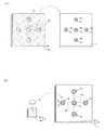
次に、通気溝を設けたメタルドーム型スイッチの作成方法について、図2を参照して説明する。
図1に示すメタルドーム型スイッチを作成するにあたって、第1及び第2固定接点1a,1bからなるスイッチ接点を備えるプリント基板1に、開口部31及び通気溝32を備える大判粘着シート3を貼り合せて、プリント基板1に各スイッチ内の空気を逃がすための通気溝32を形成する工程(図2(a)を参照)と、小片押さえシート4の粘着層4bに1つのメタルドーム2を載置して作成した小片押さえシート付きメタルドームを、開口部31の内側に配置されているスイッチ接点に搭載するとともに、前記メタルドーム2に付着している小片押さえシート4の周縁部分を大判粘着シート3の表面に貼り付ける工程(図2(b)を参照)とから、通気溝32を設けたプリント基板1の各スイッチ接点に対して、それぞれメタルドーム2を固定する。Next, a method for producing a metal dome type switch provided with a ventilation groove will be described with reference to FIG.
In producing the metal dome type switch shown in FIG. 1, a large-
図2(a)は、プリント基板1と大判粘着シート3とを示す図である。
プリント基板1の表面には、第1固定接点1aと第2固定接点1bとからなるスイッチ接点が5つ形成されている。
大判粘着シート3には、前記スイッチ接点の配設位置に対応して形成した5つの開口部31と、前記開口部31に連結する通気溝32とが形成されている。
この実施例では、ポリエステル系フィルムからなるシート基材3に開口部31を形成するとともに、当該シート基材3にアクリル系の粘着剤を印刷(塗布)することによって、開口部31を備える大判粘着シート3を作成した。またシート基材3aと粘着層(粘着剤)3bの2層から構成される大判粘着シート3に、粘着剤が塗布されていない部分からなる通気溝32を形成した。なお大判粘着シート3の粘着面には、通気溝32を除いてシート全面に粘着剤を塗布した。FIG. 2A is a diagram showing the printed
On the surface of the printed
The large-
In this embodiment, an
図2(b)は、大判粘着シート3を貼り合せたプリント基板1と、小片押さえシート付きメタルドーム2とを示す図である。
プリント基板と同等の大きさの大判粘着シート3を貼り合せたプリント基板1には、開口部31の内側にスイッチ接点が配置されるとともに、スイッチ内の空気を逃がすための通気溝32が各スイッチ接点に対して形成されている。なお、隣り合うスイッチ接点間に通気溝32を配置し、一方のスイッチがクリックされると、当該スイッチ内の空気が前記通気溝32を通って隣のスイッチ内に流れ込むように構成した。FIG. 2B is a diagram showing a printed
On the printed
また小片シート基材4aと粘着層4bとからなる小片押さえシート4のと、メタルドーム2とから構成した小片押さえシート付きメタルドームを、前記スイッチ接点の数にあわせて作成した。
なお小片押さえシート4の粘着面には、シート全面に粘着剤が塗布されており、当該小片押さえシート4の粘着層(粘着剤)4bに、一つのメタルドーム2を載置して小片押さえシート付きメタルドームを作成した。Moreover, the metal dome with the small piece press sheet | seat comprised from the small piece press sheet |
Note that an adhesive is applied to the entire adhesive surface of the small piece
なお図2に示す実施例では、小片押さえシート付きメタルドームを5つ作成し、各メタルドームをそれぞれプリント基板1のスイッチ接点に搭載するとともに、前記メタルドーム2に付着している小片押さえシート4の周縁部分を、それぞれ大判粘着シート3の表面(開口部31の周囲)に貼り付けることによって、プリント基板1の各スイッチ接点に対して個々にメタルドーム2を固定した。 In the embodiment shown in FIG. 2, five metal domes with small piece pressing sheets are prepared, and each metal dome is mounted on the switch contact of the printed
1 プリント基板
1a 第1固定接点
1b 第2固定接点
2 メタルドーム
3 大判粘着シート
3a シート基材
3b 粘着層
31 開口部
32 通気溝
4 小片押さえシート
4a 小片シート基材
4b 粘着層DESCRIPTION OF
Claims (2)
Translated fromJapanese第1及び第2固定接点(1a,1b)とからなるスイッチ接点を備えるプリント基板(1)の表面に、スイッチ接点の配設位置に対応して形成した開口部(31)と、前記開口部に連結する通気溝(32)とを備える大判粘着シート(3)を貼り合せたことによって、スイッチ内の空気を逃がすための通気溝(32)が形成され、
さらに、小片押さえシート(4)の粘着層(4b)に1つのメタルドーム(2)を載置して作成した小片押さえシート付きメタルドームを、開口部(31)の内側に配置されたスイッチ接点に搭載するとともに、スイッチ接点に搭載したメタルドーム(2)に付着している小片押さえシート(4)の周縁部分を大判粘着シート(3)の表面に貼り付けたことによって、プリント基板(1)に対してメタルドーム(2)が固定されていることを特徴とする通気溝を設けたメタルドーム型スイッチの構造。Structure of a metal dome type switch in which a metal dome (2) is fixed to a switch contact of a printed circuit board (1) using a small piece pressing sheet (4) comprising a small sheet base (4a) and an adhesive layer (4b). Because
An opening (31) formed on the surface of the printed circuit board (1) having a switch contact comprising the first and second fixed contacts (1a, 1b) corresponding to the position of the switch contact, and the opening A large-sized pressure-sensitive adhesive sheet (3) provided with a ventilation groove (32) connected to the substrate is bonded to form a ventilation groove (32) for releasing air in the switch.
Further, a switch contact disposed inside the opening (31) is a metal dome with a small piece pressing sheet prepared by placing one metal dome (2) on the adhesive layer (4b) of the small piece pressing sheet (4). In addition, the peripheral portion of the small piece pressing sheet (4) adhering to the metal dome (2) mounted on the switch contact is attached to the surface of the large-sized adhesive sheet (3). A metal dome type switch structure provided with a ventilation groove, characterized in that the metal dome (2) is fixed to.
さらに前記大判粘着シート(3)に、粘着剤が塗布されていない部分からなる通気溝(32)を形成したことを特徴とする請求項1に記載の通気溝を設けたメタルドーム型スイッチの構造。By printing the pressure-sensitive adhesive, a large-sized pressure-sensitive adhesive sheet (3) comprising a sheet base material (3a) and a pressure-sensitive adhesive layer (3b) is created,
2. The structure of a metal dome type switch provided with a ventilation groove according to claim 1, further comprising a ventilation groove (32) formed of a portion not coated with an adhesive on the large-sized adhesive sheet (3). .
Priority Applications (1)
| Application Number | Priority Date | Filing Date | Title |
|---|---|---|---|
| JP2004222117AJP2006040808A (en) | 2004-07-29 | 2004-07-29 | Metal dome type switch structure with ventilation groove |
Applications Claiming Priority (1)
| Application Number | Priority Date | Filing Date | Title |
|---|---|---|---|
| JP2004222117AJP2006040808A (en) | 2004-07-29 | 2004-07-29 | Metal dome type switch structure with ventilation groove |
Publications (1)
| Publication Number | Publication Date |
|---|---|
| JP2006040808Atrue JP2006040808A (en) | 2006-02-09 |
Family
ID=35905566
Family Applications (1)
| Application Number | Title | Priority Date | Filing Date |
|---|---|---|---|
| JP2004222117APendingJP2006040808A (en) | 2004-07-29 | 2004-07-29 | Metal dome type switch structure with ventilation groove |
Country Status (1)
| Country | Link |
|---|---|
| JP (1) | JP2006040808A (en) |
Cited By (4)
| Publication number | Priority date | Publication date | Assignee | Title |
|---|---|---|---|---|
| US20120008294A1 (en)* | 2010-07-08 | 2012-01-12 | Jahan Minoo | Printed circuit boards with embedded components |
| US8879272B2 (en) | 2009-03-09 | 2014-11-04 | Apple Inc. | Multi-part substrate assemblies for low profile portable electronic devices |
| US10515771B2 (en) | 2016-07-28 | 2019-12-24 | Panasonic Intellectual Property Management Co., Ltd. | Switch unit |
| US11114259B2 (en) | 2017-02-15 | 2021-09-07 | Panasonic Intellectual Property Management Co., Ltd. | Switch body |
- 2004
- 2004-07-29JPJP2004222117Apatent/JP2006040808A/enactivePending
Cited By (6)
| Publication number | Priority date | Publication date | Assignee | Title |
|---|---|---|---|---|
| US8879272B2 (en) | 2009-03-09 | 2014-11-04 | Apple Inc. | Multi-part substrate assemblies for low profile portable electronic devices |
| US20120008294A1 (en)* | 2010-07-08 | 2012-01-12 | Jahan Minoo | Printed circuit boards with embedded components |
| US8339798B2 (en)* | 2010-07-08 | 2012-12-25 | Apple Inc. | Printed circuit boards with embedded components |
| US8804363B2 (en) | 2010-07-08 | 2014-08-12 | Apple Inc. | Printed circuit boards with embedded components |
| US10515771B2 (en) | 2016-07-28 | 2019-12-24 | Panasonic Intellectual Property Management Co., Ltd. | Switch unit |
| US11114259B2 (en) | 2017-02-15 | 2021-09-07 | Panasonic Intellectual Property Management Co., Ltd. | Switch body |
Similar Documents
| Publication | Publication Date | Title |
|---|---|---|
| JP4413892B2 (en) | Key sheet | |
| US20090223801A1 (en) | Member for push button switch and manufacturing method thereof | |
| JP4417588B2 (en) | Metal dome sheet | |
| JP2005166609A (en) | Key sheet module | |
| CN101490776A (en) | Electroluminescent lamp membrane switch | |
| JP2008016187A (en) | Key sheet and push-button switch | |
| JP2010272384A (en) | Seat with movable contact and method for manufacturing the same | |
| JP2002245898A (en) | Movable contact body, manufacturing method thereof, and panel switch using the movable contact body | |
| EP1137028B1 (en) | Sheet with plate springs and switch device using same | |
| JP2003257282A (en) | Sheet with movable contact | |
| JP5194764B2 (en) | Movable contact body and manufacturing method thereof | |
| JP2010015200A (en) | Protection panel with touch input function for electronic equipment display window | |
| CN101856923B (en) | Pattern transfer method | |
| JP2006040808A (en) | Metal dome type switch structure with ventilation groove | |
| CN1145993C (en) | Switches, locking plates for switches and fixing methods for locking plates for switches | |
| JP2002270062A (en) | Push switch | |
| US20090205943A1 (en) | Panel switch | |
| JP2006294429A (en) | Movable contact body and panel switch configured using the same | |
| JP5249650B2 (en) | Membrane switch and manufacturing method thereof | |
| JP2006318766A (en) | Key top member bearing cutout character that has no break and its manufacturing method | |
| JP3538030B2 (en) | Switch structure and switch plate | |
| JP4439418B2 (en) | Functional display sheet, method for manufacturing the same, and method for manufacturing a switch using the same | |
| US20050167258A1 (en) | Movable contact unit | |
| JP2011096477A (en) | Sheet pasting device, and method of manufacturing switch module | |
| JP2005259418A (en) | Movable contact body and manufacturing method thereof |