JP2006036849A - System for treating and utilizing biomass and method for treating and utilizing biomass gas - Google Patents
System for treating and utilizing biomass and method for treating and utilizing biomass gasDownload PDFInfo
- Publication number
- JP2006036849A JP2006036849AJP2004215969AJP2004215969AJP2006036849AJP 2006036849 AJP2006036849 AJP 2006036849AJP 2004215969 AJP2004215969 AJP 2004215969AJP 2004215969 AJP2004215969 AJP 2004215969AJP 2006036849 AJP2006036849 AJP 2006036849A
- Authority
- JP
- Japan
- Prior art keywords
- biogas
- gas
- gas holder
- utilization system
- desulfurization
- Prior art date
- Legal status (The legal status is an assumption and is not a legal conclusion. Google has not performed a legal analysis and makes no representation as to the accuracy of the status listed.)
- Pending
Links
Images


Classifications
- Y—GENERAL TAGGING OF NEW TECHNOLOGICAL DEVELOPMENTS; GENERAL TAGGING OF CROSS-SECTIONAL TECHNOLOGIES SPANNING OVER SEVERAL SECTIONS OF THE IPC; TECHNICAL SUBJECTS COVERED BY FORMER USPC CROSS-REFERENCE ART COLLECTIONS [XRACs] AND DIGESTS
- Y02—TECHNOLOGIES OR APPLICATIONS FOR MITIGATION OR ADAPTATION AGAINST CLIMATE CHANGE
- Y02C—CAPTURE, STORAGE, SEQUESTRATION OR DISPOSAL OF GREENHOUSE GASES [GHG]
- Y02C20/00—Capture or disposal of greenhouse gases
- Y02C20/40—Capture or disposal of greenhouse gases of CO2
- Y—GENERAL TAGGING OF NEW TECHNOLOGICAL DEVELOPMENTS; GENERAL TAGGING OF CROSS-SECTIONAL TECHNOLOGIES SPANNING OVER SEVERAL SECTIONS OF THE IPC; TECHNICAL SUBJECTS COVERED BY FORMER USPC CROSS-REFERENCE ART COLLECTIONS [XRACs] AND DIGESTS
- Y02—TECHNOLOGIES OR APPLICATIONS FOR MITIGATION OR ADAPTATION AGAINST CLIMATE CHANGE
- Y02E—REDUCTION OF GREENHOUSE GAS [GHG] EMISSIONS, RELATED TO ENERGY GENERATION, TRANSMISSION OR DISTRIBUTION
- Y02E50/00—Technologies for the production of fuel of non-fossil origin
- Y02E50/30—Fuel from waste, e.g. synthetic alcohol or diesel
- Y—GENERAL TAGGING OF NEW TECHNOLOGICAL DEVELOPMENTS; GENERAL TAGGING OF CROSS-SECTIONAL TECHNOLOGIES SPANNING OVER SEVERAL SECTIONS OF THE IPC; TECHNICAL SUBJECTS COVERED BY FORMER USPC CROSS-REFERENCE ART COLLECTIONS [XRACs] AND DIGESTS
- Y02—TECHNOLOGIES OR APPLICATIONS FOR MITIGATION OR ADAPTATION AGAINST CLIMATE CHANGE
- Y02W—CLIMATE CHANGE MITIGATION TECHNOLOGIES RELATED TO WASTEWATER TREATMENT OR WASTE MANAGEMENT
- Y02W10/00—Technologies for wastewater treatment
- Y02W10/20—Sludge processing
- Y—GENERAL TAGGING OF NEW TECHNOLOGICAL DEVELOPMENTS; GENERAL TAGGING OF CROSS-SECTIONAL TECHNOLOGIES SPANNING OVER SEVERAL SECTIONS OF THE IPC; TECHNICAL SUBJECTS COVERED BY FORMER USPC CROSS-REFERENCE ART COLLECTIONS [XRACs] AND DIGESTS
- Y02—TECHNOLOGIES OR APPLICATIONS FOR MITIGATION OR ADAPTATION AGAINST CLIMATE CHANGE
- Y02W—CLIMATE CHANGE MITIGATION TECHNOLOGIES RELATED TO WASTEWATER TREATMENT OR WASTE MANAGEMENT
- Y02W30/00—Technologies for solid waste management
- Y02W30/20—Waste processing or separation
Landscapes
- Processing Of Solid Wastes (AREA)
- Gas Separation By Absorption (AREA)
- Treatment Of Sludge (AREA)
Abstract
Description
Translated fromJapanese本発明は、バイオガスの処理利用システム及びバイオガスの処理利用方法に関し、詳細には、下水処理場、その他有機性廃棄物の嫌気性発酵(消化)設備を有する処理場において、前記嫌気性発酵設備から発生する、メタン(CH4)及び二酸化炭素(CO2)を主成分とするバイオガス(消化ガス)の処理利用技術に関するものである。The present invention relates to a biogas treatment and utilization system and a biogas treatment and utilization method, and more specifically, in an anaerobic fermentation in a sewage treatment plant and other treatment plants having anaerobic fermentation (digestion) facilities for organic waste. The present invention relates to a processing and utilization technique of biogas (digestion gas) mainly composed of methane (CH4 ) and carbon dioxide (CO2 ) generated from equipment.
下水汚泥、畜舎からの糞尿、生ごみ等の有機性廃棄物を消化槽で嫌気性発酵すると、バイオガス(消化ガス)が発生する。このバイオガスは、一般に、メタン(CH4)を約60容量%(55〜65容量%程度)、二酸化炭素(CO2)を約35容量%(30〜40容量%程度)、硫化水素(H2S)等の不純ガスを僅かに含む組成を有する。このバイオガスの利用の仕方として、特開昭52−48285号公報(特許文献1)には、消化槽で発生したバイオガスを脱硫してガスホルダに蓄えた後、ガスタービンに供給し、燃料として用いて電力及び熱エネルギーを得るシステムが記載されている。Biogas (digestion gas) is generated when anaerobic fermentation of organic waste such as sewage sludge, manure from livestock barn, and garbage in a digestion tank. This biogas is generally composed of about 60% by volume (about 55 to 65% by volume) of methane (CH4 ), about 35% by volume (about 30 to 40% by volume) of carbon dioxide (CO2 ), hydrogen sulfide (H2 It has a composition containing a slight amount of impure gas such as S). As a method of using this biogas, Japanese Patent Application Laid-Open No. 52-48285 (Patent Document 1) discloses that biogas generated in a digestion tank is desulfurized and stored in a gas holder, then supplied to a gas turbine and used as fuel. A system has been described that uses it to obtain power and thermal energy.
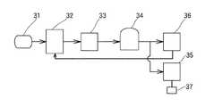
図5は、上記ガスタービンを利用した下水汚泥処理システムの構成例を示す概略図である。図5に示す従来のシステムでは、下水汚泥等の有機性廃棄物31を導入し嫌気性発酵を行なってバイオガスを発生させる消化槽32と、この消化槽32で発生したバイオガスに含まれるH2Sを除去(低減)する脱硫装置33と、脱硫処理後のバイオガスを蓄えるガスホルダ34と、蓄えたバイオガスを燃料として用いるガスタービン35及び加温用ボイラ36とを備えて構成されている。なお、符号37はガスタービン35に連結された発電機である。また、加温用ボイラ36は、消化槽32の加温に用いるものである。FIG. 5 is a schematic diagram showing a configuration example of a sewage sludge treatment system using the gas turbine. In the conventional system shown in FIG. 5, an
上記構成においては、ガスホルダ34に蓄えられたバイオガスは、加温用ボイラ36に加えて発電用ガスタービン35の燃料としても用いるようにしたので、それまでの加温用ボイラだけの場合に比較して、多量に発生するバイオガスを無駄に燃焼させることなく有効に活用することができる。また、ガスホルダ34に蓄えられたバイオガスは脱硫処理が施されてH2Sが低減されているので、燃料として用いた場合に燃焼機器などの腐食を防ぐことができる。In the above configuration, since the biogas stored in the
一方、上述のようなシステムに対して近年、新たな改善が特開2002−60767号公報(特許文献2)などに提案されている。 On the other hand, in recent years, a new improvement has been proposed in Japanese Patent Laid-Open No. 2002-60767 (Patent Document 2) and the like for the above-described system.
特許文献2に提案のものは、次のようなものである。即ち、下水場の普及率向上や生活形態の変化に伴って、シャンプーやリンス等の頭髪仕上げ剤、カーワックス等の撥水剤などの消費が増加し、これらに含有されているシロキサン化合物が下水中に多量に流されるようになってきている。このシロキサン化合物を含む汚泥等の有機性廃棄物を上述の如きシステムで処理すると、嫌気性発酵(消化)過程でシロキサン化合物がバイオガス側に揮散する。このシロキサン化合物が揮散したバイオガスを後段の発電用の燃料ガスとして用いた場合には、シロキサン化合物がシリカ(SiO2)となって、発電用機器内に付着、析出し、発電用機器の摩耗、劣化を起こすなどといった問題が生じる。そこで、提案のものでは、発電用の燃料としてバイオガスを用いる前に、揮散しているシロキサン化合物を除去し精製するというものである。The thing proposed in
しかし、上述の如きシステムで生成されたバイオガスは、CH4の他にCO2、H2S及び蒸気(H2O)等のガスを含んでおり、そのままでは天然ガスに代わる燃料として使用することができない。一方、上記のようにしてバイオガスから精製したメタンガスを燃料として用いた場合には、燃焼時に発生するCO2はもともと生物が大気中のCO2を固定したものであるため、地球温暖化の原因となるCO2の量を増やすことにはならないといったメリットを有する。
本発明は、上記の事情に鑑みてなしたものであって、その目的は、CO2、H2S及び蒸気(H2O)等の不純ガスの濃度を低減しCH4濃度の高いバイオガスを供給し、大気中へ排気されるCH4の量を低減し得るバイオガスの処理利用システムを提供するものである。他の目的は、僅かな量であっても温室効果に影響を及ぼすCH4を系外に排出することのない、バイオガスの処理利用システムを提供するものであり、更には、シロキサン化合物を除去してなるバイオガスの処理利用システムを提供するものである。The present invention has been made in view of the above circumstances, and its purpose is to reduce the concentration of impurity gases such as CO2 , H2 S, and steam (H2 O), and to increase the concentration of CH4 in biogas. And a biogas treatment and utilization system that can reduce the amount of CH4 exhausted to the atmosphere. Another object of the present invention is to provide a biogas treatment and utilization system that does not emit CH4 that affects the greenhouse effect even if it is in a small amount, and further removes siloxane compounds. A biogas treatment and utilization system is provided.
本発明は、上記の目的を達成するため以下に述べる構成としたものである。即ち、本発明に係る請求項1の発明は、バイオガスを発生させる消化槽と、発生したバイオガスを脱硫処理する脱硫装置と、脱硫後のバイオガスを蓄える第1ガスホルダと、蓄えたバイオガスを精製して可燃成分を濃縮させるバイオガス精製装置と、精製したバイオガスを蓄える第2ガスホルダと、蓄えた精製バイオガスを消費するバイオガス消費機器とを備え、前記バイオガス精製装置が、バイオガスと吸収液とを0.2Mpa以上の高圧雰囲気下で接触させ、前記吸収液に二酸化炭素などの不純ガスを吸収させるバイオガス精製装置であることを特徴とするバイオガスの処理利用システムである。
上記において吸収液としては水を利用することができる。この水は水道水や蒸留水のみならず、膜を利用した処理水やメタン発酵により処理した水を利用することもできるし、通常の排水を好気処理した水を利用することもできる。The present invention has the following configuration in order to achieve the above object. That is, the invention of
In the above, water can be used as the absorbing liquid. As this water, not only tap water and distilled water but also water treated with a membrane or water treated by methane fermentation can be used, or water obtained by aerobic treatment of normal waste water can be used.
上記の構成では、脱硫装置を備えた上に、バイオガス精製装置として、バイオガスと吸収液とを0.2Mpa以上の高圧雰囲気下で接触させ、前記吸収液に二酸化炭素などの不純ガスを吸収させ得る所謂高圧吸収式のバイオガス精製装置を備えているので、CO2、H2S及び蒸気(H2O)等の不純ガスの濃度を低減しCH4濃度の高いバイオガスを得ることができる。また、バイオガスの精製方法として高圧水法を利用しているため大気中へ排気されるCH4の量を低減させることができる。In the above configuration, the desulfurization device is provided, and the biogas purification device is brought into contact with the biogas and the absorption liquid in a high-pressure atmosphere of 0.2 Mpa or more, and the impure gas such as carbon dioxide is absorbed into the absorption liquid. A so-called high-pressure absorption biogas purification device that can be made to reduce the concentration of impure gases such as CO2 , H2 S, and steam (H2 O), thereby obtaining a biogas with a high CH4 concentration. it can. Further, since the high-pressure water method is used as a biogas purification method, the amount of CH4 exhausted to the atmosphere can be reduced.
また、本発明に係る請求項2の発明は、バイオガスを発生させる消化槽と、発生したバイオガスを脱硫処理する脱硫装置と、脱硫後のバイオガスを蓄える第1ガスホルダと、蓄えたバイオガスを精製して可燃成分を濃縮させるバイオガス精製装置と、精製したバイオガスを蓄える第2ガスホルダと、蓄えた精製バイオガスを消費するバイオガス消費機器とを備えるとともに、前記バイオガス精製装置と第1ガスホルダとの間にバイオガス精製装置からの排気ガスをガスホルダに戻す流路を設けてなることを特徴とするバイオガスの処理利用システムである。 Further, the invention of
上記の構成では、バイオガス精製装置と第1ガスホルダとの間にバイオガス精製装置からの排気ガスをガスホルダに戻す流路を設けているので、バイオガス精製装置で捕捉された僅かな量のCH4やH2Sなどの不純ガスは再び第1ガスホルダに戻すことができ、脱硫処理やバイオガス精製装置を循環することになるので、温室効果に影響を及ぼすCH4を系外に排出することが抑制される。In the above configuration, since the flow path for returning the exhaust gas from the biogas purification device to the gas holder is provided between the biogas purification device and the first gas holder, a small amount of CH captured by the biogas purification device is provided. Impurities such as4 and H2 S can be returned to the first gas holder again and circulated through the desulfurization process and biogas refining equipment, so that CH4 affecting the greenhouse effect must be discharged out of the system. Is suppressed.
また、本発明に係る請求項3の発明は、上記請求項2の発明のバイオガスの処理利用システムにおいて、バイオガス精製装置が、バイオガスと吸収液とを0.2Mpa以上の高圧雰囲気下で接触させ、前記吸収液に二酸化炭素などの不純ガスを吸収させるバイオガス精製装置とするものである。 According to a third aspect of the present invention, in the biogas processing and utilization system according to the second aspect of the present invention, the biogas purifying apparatus is configured to remove the biogas and the absorbing liquid in a high-pressure atmosphere of 0.2 Mpa or more. The biogas purification apparatus is made to contact and absorb the impure gas such as carbon dioxide in the absorption liquid.
また、本発明に係る請求項4の発明は、上記請求項2又は3の発明のバイオガスの処理利用システムにおいて、第1ガスホルダとバイオガス精製装置との間にメタンガスと二酸化炭素の濃度分析計を設けてなるものである。 According to a fourth aspect of the present invention, in the biogas processing and utilization system according to the second or third aspect of the present invention, a methane gas and carbon dioxide concentration analyzer is provided between the first gas holder and the biogas purification device. Is provided.
また、本発明に係る請求項5の発明は、上記請求項4の発明のバイオガスの処理利用システムにおいて、第1ガスホルダとバイオガス精製装置との間に分岐流路を設けるとともに当該分岐流路にバイオガス消費機器を設け、メタンガスと二酸化炭素の濃度に応じて、前記バイオガス消費機器と前記バイオガス精製装置への流量を調整する調整弁をバイオガス精製装置の前に設けてなるものである。 According to a fifth aspect of the present invention, in the biogas treatment and utilization system according to the fourth aspect of the present invention, a branch flow path is provided between the first gas holder and the biogas purification device, and the branch flow path is provided. A biogas consuming device is provided, and an adjustment valve for adjusting the flow rate to the biogas consuming device and the biogas purification device according to the concentrations of methane gas and carbon dioxide is provided in front of the biogas purification device. is there.
また、本発明に係る請求項6の発明は、上記請求項1〜4のいずれかの発明のバイオガスの処理利用システムにおいて、第1ガスホルダの後段にシロキサン除去装置を設けてなるものである。 According to a sixth aspect of the present invention, in the biogas treatment and utilization system according to any one of the first to fourth aspects of the present invention, a siloxane removing device is provided after the first gas holder.
また、本発明に係る請求項7の発明は、バイオガスをバイオガス消費機器で用いるための処理利用方法であって、消化槽から発生したバイオガスを脱硫処理し、硫黄化合物が除去された後のバイオガスを、吸収液と0.2Mpa以上の高圧雰囲気下で接触させ、吸収液中に二酸化炭素などの不純ガスを吸収させ、バイオガス中のメタン濃度を高めて回収することを特徴とするバイオガスの処理利用方法である。 Further, the invention of
本発明に係るバイオガスの処理利用システムによれば、脱硫装置を備えた上に、バイオガス精製装置として、高圧吸収式のバイオガス精製装置を備えているので、CO2、H2S及び蒸気(H2O)等の不純ガスの濃度を低減しCH4濃度の高いバイオガスを得ることができる。また、バイオガス精製装置と第1ガスホルダとの間にバイオガス精製装置からの排気ガスを第1ガスホルダに戻す流路を設けることで、温室効果に影響を及ぼすCH4を系外に排出すること無くCH4濃度の高いバイオガスを得ることができる。また更に、第1ガスホルダとバイオガス精製装置との間にシロキサン除去装置を設けることで、シロキサン化合物を除去することができ、後段の機器の摩耗、劣化を防止できる。The biogas treatment and utilization system according to the present invention includes a desulfurization device and a high-pressure absorption biogas purification device as a biogas purification device, so that CO2 , H2 S and steam are provided. A biogas having a high CH4 concentration can be obtained by reducing the concentration of impure gas such as (H2 O). Further, by providing a flow path for returning the exhaust gas from the biogas purification device to the first gas holder between the biogas purification device and the first gas holder, CH4 that affects the greenhouse effect is discharged out of the system. Biogas having a high CH4 concentration can be obtained. Furthermore, by providing a siloxane removal device between the first gas holder and the biogas purification device, the siloxane compound can be removed, and wear and deterioration of the subsequent equipment can be prevented.
本発明に係るバイオガスの処理利用システムにおいては、消化槽で発生したバイオガスは、脱硫装置で脱硫した後、第1ガスホルダに蓄え、この第1ガスホルダからバイオガス精製装置に供給される。バイオガス精製装置では、バイオガスを精製して可燃成分(CH4)を濃縮させる。その精製したバイオガスは、第2ガスホルダに蓄え、その第2ガスホルダからバイオガスを消費するバイオガス消費機器へ供給される。In the biogas processing and utilization system according to the present invention, the biogas generated in the digestion tank is desulfurized by the desulfurization apparatus, stored in the first gas holder, and supplied from the first gas holder to the biogas purification apparatus. In the biogas purification apparatus, the biogas is purified and the combustible component (CH4 ) is concentrated. The purified biogas is stored in the second gas holder, and is supplied from the second gas holder to a biogas consuming device that consumes the biogas.
上記バイオガス精製装置としては、膜分離方式、圧力スイング方式、あるいはガス吸収方式が使用できるが、バイオガスと水を2気圧以上の高圧状態で接触させる高圧吸収式が、水はもとより処理水(下水等の排水の処理後の水)などの吸収液が使用できて装置コストが安価にできること、また残留H2Sが除去可能であることなどから望ましい。しかし、いずれのバイオガス精製装置であっても、バイオガスの精製により分離されたCO2を大気中に排気することになるが、この排気ガス中には、CH4が少なからず(5〜30容量%程度)存在するが、高圧水法を利用することで大気中へ排気されるCH4を低減することができる。更に、本発明においては、このバイオガス精製装置と第1ガスホルダとの間にバイオガス精製装置からの排気ガスを第1ガスホルダに戻す流路を設け、温室効果に影響を及ぼすCH4を系外に排出することなく循環せしめることとしたものである。このように構成することにより、大気中へ放出されるCH4の量を更に低減もしくは排出しないようにすることができる。また、本発明においては、バイオガス精製装置やボイラなどに供給する前の、ガスホルダを出た後に、メタンガスと二酸化炭素の濃度分析計又は/及びシロキサン除去装置を設けることができる。As the biogas purification apparatus, a membrane separation system, a pressure swing system, or a gas absorption system can be used. A high-pressure absorption system in which biogas and water are brought into contact with each other in a high-pressure state of 2 atm or higher is used as well as treated water ( This is desirable because an absorption liquid such as water after treatment of wastewater such as sewage can be used and the apparatus cost can be reduced, and residual H2 S can be removed. However, in any of the biogas purification apparatuses, CO2 separated by biogas purification is exhausted into the atmosphere, but CH4 is not a little (5 to 30) in the exhaust gas. However, CH4 exhausted into the atmosphere can be reduced by using the high pressure water method. Furthermore, in the present invention, a flow path for returning exhaust gas from the biogas purification device to the first gas holder is provided between the biogas purification device and the first gas holder, and CH4 that affects the greenhouse effect is excluded from the system. It is decided to circulate without discharging. With this configuration, the amount of CH4 released into the atmosphere can be further reduced or not discharged. In the present invention, a concentration analyzer for methane gas and carbon dioxide and / or a siloxane removal device can be provided after leaving the gas holder before being supplied to a biogas purification device or a boiler.
以下、本発明の実施の形態を図面に基づいて説明する。図1は、本発明に係るバイオガスの処理利用システムの構成例を示す概略説明図、図2は、図1におけるバイオガス精製装置として高圧吸収方式を採用した場合の要部の構成例を示す概略説明図である。図において、1は消化槽、2は脱硫装置、3は第1ガスホルダ、4はバイオガス精製装置、5は第2ガスホルダ、6はバイオガス消費機器である。 Hereinafter, embodiments of the present invention will be described with reference to the drawings. FIG. 1 is a schematic explanatory view showing a configuration example of a biogas processing and utilization system according to the present invention, and FIG. 2 shows a configuration example of a main part when a high-pressure absorption method is adopted as the biogas purification apparatus in FIG. It is a schematic explanatory drawing. In the figure, 1 is a digester, 2 is a desulfurization device, 3 is a first gas holder, 4 is a biogas purification device, 5 is a second gas holder, and 6 is a biogas consuming device.
消化槽1は、ここに下水汚泥等の有機性廃棄物7を導入し嫌気性発酵を行なってバイオガスを発生させる。消化槽1で発生したバイオガスには、少なからずH2Sなどの硫黄化合物を含む(多くて1000ppm前後)ことが懸念されるので、このH2Sなどを、脱硫装置2を通すことで除去し、除去後のバイオガスを第1ガスホルダ3に蓄える。この第1ガスホルダ3に蓄えたバイオガスは、大略、CH4を約60容量%と、CO2を約40容量%含む組成を有する。第1ガスホルダ3に蓄えたバイオガスは、バイオガス精製装置4に供給される。The
バイオガス精製装置4は、ガス吸着塔8、ガス脱着塔9及び大気圧開放タンク10を備えて構成されている。第1ガスホルダ3から出たバイオガスは、ガス圧縮機11で所定圧力に加圧され、冷却器12で冷却された後、ガス吸着塔8の下部より内部に送気される。一方、ガス吸着塔8の上部からは、吸着液(処理水)が高圧ポンプ13により所定圧力に加圧され注水される。 The
上記ガス吸着塔8における処理水とバイオガスの気液対向流によって、バイオガス中のCO2が処理水に溶解、除去され、可燃成分であるCH4が95容量%以上に濃縮されてガス吸着塔8の頂部から排出され、ガス乾燥器14で乾燥されて第2ガスホルダ5に蓄えられる。一方、CO2を溶解した処理水は、僅かにCH4をも溶解しており、ガス吸着塔8の下部に溜まる。また、前記ガス乾燥器14においても処理水が溜まるので、これら溜まった処理水は、ガス脱着塔9に供給し、CH4やCO2などのガス成分を分離し、更に分離後の処理水を大気圧開放タンク10に送水し大気圧開放するとともに排水を行なう。The gas adsorption between the treated water and the biogas in the
他方、上記バイオガス精製装置4により95容量%以上に濃縮され第2ガスホルダ5に蓄えられたCH4は、必要に応じてバイオガスの消費機器6に供給される。バイオガスの消費機器6としては、例えば、余剰ガス燃焼装置、ガスエンジン、ガスタービン、温水ボイラ、更にはガス充填装置を介して天然ガスを燃料とした自動車(CNG自動車)の充填容器などの消費機器が例示できる。On the other hand, CH4 concentrated to 95% by volume or more by the
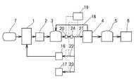
図3は、本発明に係るバイオガスの処理利用システムの別の実施形態の構成例を示す概略説明図である。図において、1は消化槽、2は脱硫装置、3は第1ガスホルダ、15はバイオガス精製装置、5は第2ガスホルダ、6はバイオガス消費機器であって、上記実施形態と同じ機能を有する装置は同じ符号をもって示す。 FIG. 3 is a schematic explanatory diagram showing a configuration example of another embodiment of the biogas processing and utilization system according to the present invention. In the figure, 1 is a digestion tank, 2 is a desulfurization device, 3 is a first gas holder, 15 is a biogas purification device, 5 is a second gas holder, and 6 is a biogas consuming device, which has the same function as the above embodiment. Devices are indicated with the same reference numerals.
消化槽1は、ここに下水汚泥等の有機性廃棄物7を導入し嫌気性発酵を行なってバイオガスを発生させる。消化槽1で発生したバイオガスには、少なからずH2Sなどの硫黄化合物を含む(多くて1000ppm前後)ことが懸念されるので、このH2Sなどを、脱硫装置2を通すことで除去し、除去後のバイオガスを第1ガスホルダ3に蓄える。この第1ガスホルダ3に蓄えたバイオガスは、大略、CH4を約60容量%と、CO2を約40容量%含む組成を有する。The
第1ガスホルダ3に蓄えたバイオガスは、その一部が第1ガスホルダ3から、例えばバイオガスの消費機器6の1つである加温用ボイラ16に供給され、消化槽1の発酵効率を高めるための加温に用いられる。また、必要によりバイオガスの消費機器6の1つであるガスタービン17などにも供給される。他は、第1ガスホルダ3からバイオガス精製装置15に供給される。このバイオガス精製装置15に供給されたバイオガスは、CO2が除去されて可燃成分であるCH4が95容量%以上に濃縮される。このバイオガスの精製過程でバイオガス精製装置15によって除去されたCO2を主成分(約95容量%)とする排気ガス中には、約5容量%のCH4が存在している。この排気ガスは、第1ガスホルダ3とバイオガス精製装置15との間に設けられた戻し流路(管路)18を介して、バイオガス精製装置15から第1ガスホルダ3へと戻される。一方、95容量%以上に濃縮されたCH4は、第2ガスホルダ5に蓄えられ、上述の実施形態と同様に必要に応じてバイオガスの消費機器6に供給される。バイオガスの消費機器6としては、例えば、余剰ガス燃焼装置、ガスエンジン、温水ボイラ、更にはガス充填装置を介して天然ガスを燃料とした自動車(CNG自動車)の充填容器などの消費機器が例示できる。
また、本実施形態においてはバイオガス精製装置の手前で分岐し、バイオガス消費機器として加温用ボイラやガスタービンを用いたが、これに限定されず、ガスエンジンや、余剰ガス燃焼装置といったものも利用できる。A part of the biogas stored in the
Further, in this embodiment, a heating boiler or a gas turbine is used as a biogas consuming device that branches off before the biogas purifying device, but is not limited to this, such as a gas engine or a surplus gas combustion device. Can also be used.
なお、図3において、19は濃度制御装置であって、この濃度制御装置19は、第1ガスホルダ3から送気されるバイオガス中のCH4、CO2の濃度を濃度計20によって測定し、その測定結果を基にバイオガス精製装置15、加温用ボイラ16やガスタービン17へのバイオガスの供給量を流量調整弁21〜23を介して調整するものである。
本実施形態においては、CH4、CO2濃度計の後段に分岐路を設け、加温用ボイラーやガスタービンへ分岐する構成としたが、分岐路の位置はこれに限定されず、濃度計の手前で分岐する構成としても良い。
本実施形態においては、ガス精製装置での排気ガスを第1ガスホルダに戻すため、バイオガス中のCO2濃度が上昇する。これをそのまま放置すると、ガス精製装置への負荷が大きくなるとともに、得られるCH4の純度が低下するおそれがある。そのため、分岐路で分岐し、ガスタービンや加温用ボイラでバイオガスの一部を消費することにより、系外にCO2を排出し、系内のCO2濃度がある一定以上の濃度になることを防いでいる。
また、バイオガス精製装置へ供給されるCH4とCO2濃度を測定し、CO2の割合がある一定以下になるようにバイオガス精製装置側と加温用ボイラ、ガスタービンに流す流量を調整するので、バイオガス精製装置に供給されるバイオガス中のCO2濃度を調整することが可能となる。バイオガス精製装置に供給されるバイオガス中のCO2濃度としては例えば60%以下になるように加温用ボイラーやガスタービン側に取り出すバイオガスの量を調整することが好ましく、更には50%以下になるように調整するのが好ましい。また、24はシロキサン化合物の除去装置であって、本例では第1ガスホルダ3の出側に設置し、第1ガスホルダ3から送気されるバイオガス中のシロキサン化合物を除去するようにしたが、ガスタービン17などの、必要とするバイオガスの消費機器の入り側に設置してもよい。In FIG. 3, 19 is a concentration control device, and this
In the present embodiment, a branch path is provided at the subsequent stage of the CH4 and CO2 concentration meter, and it is configured to branch to a heating boiler or a gas turbine. However, the position of the branch path is not limited to this, and the concentration meter It is good also as a structure branched before this.
In the present embodiment, the exhaust gas in the gas purifier is returned to the first gas holder, so that the CO2 concentration in the biogas increases. If this is left as it is, the load on the gas purifier increases and the purity of the resulting CH4 may be reduced. Therefore, by branching at a branch path and consuming part of biogas with a gas turbine or a heating boiler, CO2 is discharged out of the system, and the CO2 concentration in the system becomes a certain level or higher. It prevents that.
Also, the CH4 and CO2 concentrations supplied to the biogas purifier are measured, and the flow rate to the biogas purifier, the heating boiler, and the gas turbine are adjusted so that the CO2 ratio is below a certain level. Therefore, it is possible to adjust the CO2 concentration in the biogas supplied to the biogas purification apparatus. It is preferable to adjust the amount of biogas to be taken out to the heating boiler or gas turbine so that the CO2 concentration in the biogas supplied to the biogas purifier is, for example, 60% or less, and further 50% It is preferable to adjust to be as follows. In addition, 24 is a siloxane compound removal device, which is installed on the outlet side of the
図4は、バイオガス精製装置15として高圧水方式を採用した場合の要部の構成例を示す概略説明図である。上記実施形態と同じ機能を有する装置は同じ符号をもって示す。この図4におけるバイオガス精製装置15は、ガス吸着塔8、ガス脱着塔9及び大気圧開放タンク10を備えて構成されている。第1ガスホルダ3から出たバイオガスは、ガス圧縮機11で所定圧力に加圧され、冷却器12で冷却された後、ガス吸着塔8の下部より内部に送気される。一方、ガス吸着塔8の上部からは、吸着液(処理水)が高圧ポンプ13により所定圧力に加圧され注水される。
この吸着液とバイオガスを接触させる圧力としてはCO2の吸着液への吸収効率と、加圧にかかるエネルギーの観点から、0.2〜1MPaで行うのが好ましく、さらに好ましくは0.6〜0.9MPaで行うのが好ましい。FIG. 4 is a schematic explanatory diagram showing a configuration example of a main part when a high-pressure water system is adopted as the biogas purification device 15. Devices having the same functions as those in the above embodiment are denoted by the same reference numerals. The biogas purification apparatus 15 in FIG. 4 includes a
The pressure at which the adsorbed liquid and biogas are brought into contact is preferably 0.2 to 1 MPa, more preferably 0.6 to 0.6 from the viewpoint of the absorption efficiency of CO2 into the adsorbed liquid and the energy required for pressurization. It is preferable to carry out at 0.9 MPa.
上記ガス吸着塔8における処理水とバイオガスの気液対向流によって、バイオガス中のCO2が処理水に溶解、除去され、可燃成分であるCH4が濃縮されてガス吸着塔8の頂部から排出され、ガス乾燥器14で乾燥されて第2ガスホルダ5に蓄えられる。一方、CO2を溶解した処理水は、僅かにCH4をも溶解しており、ガス吸着塔8の下部に溜まる。また、前記ガス乾燥器14においても処理水が溜まるので、これら溜まった処理水は、ガス脱着塔9に供給し、CH4やCO2などのガス成分を分離する。この分離では大気圧より高圧であるため分離後の処理水中には、なおCH4やCO2などのガス成分が大気圧下で放出される可能性があるため、分離後の処理水を大気圧開放タンク10に送水し大気圧開放を行なう。この大気圧開放タンク10内で放出されたCH4やCO2などのガス及び前記ガス脱着塔9で分離されたCH4やCO2などのガスは、戻し流路(管路)18を介して第1ガスホルダ3へと戻される。From the gas-liquid counter flow of the treated water and the biogas in the
1:消化槽 2:脱硫装置 3:第1ガスホルダ
4:バイオガス精製装置 5:第2ガスホルダ 6:バイオガス消費機器
7:有機性廃棄物 8:ガス吸着塔 9:ガス脱着塔
10:大気圧開放タンク 11:ガス圧縮機 12:冷却器
13:高圧ポンプ 14:ガス乾燥器 15:バイオガス精製装置
16:加温用ボイラ 17:ガスタービン 18:戻し流路
19:濃度制御装置 20:濃度計 21〜23:流量調整弁
24:シロキサン化合物の除去装置
1: Digestion tank 2: Desulfurization equipment 3: First gas holder 4: Biogas purification equipment 5: Second gas holder 6: Biogas consuming equipment 7: Organic waste 8: Gas adsorption tower 9: Gas desorption tower 10: Atmospheric pressure Open tank 11: Gas compressor 12: Cooler 13: High pressure pump 14: Gas dryer 15: Biogas refining device 16: Heating boiler 17: Gas turbine 18: Return flow path 19: Concentration controller 20: Concentration meter 21-23: Flow control valve 24: Siloxane compound removal device
Claims (7)
Translated fromJapaneseIt is a processing utilization method for using biogas in a biogas consuming device, wherein the biogas generated from the digestion tank is desulfurized, and the biogas after the sulfur compound is removed is absorbed into the absorbing solution and 0.2 Mpa or more. A method for processing and utilizing a biogas, comprising contacting under a high-pressure atmosphere, absorbing an impure gas such as carbon dioxide in an absorbent, and increasing the concentration of methane in the biogas to recover.
Priority Applications (1)
| Application Number | Priority Date | Filing Date | Title |
|---|---|---|---|
| JP2004215969AJP2006036849A (en) | 2004-07-23 | 2004-07-23 | System for treating and utilizing biomass and method for treating and utilizing biomass gas |
Applications Claiming Priority (1)
| Application Number | Priority Date | Filing Date | Title |
|---|---|---|---|
| JP2004215969AJP2006036849A (en) | 2004-07-23 | 2004-07-23 | System for treating and utilizing biomass and method for treating and utilizing biomass gas |
Publications (1)
| Publication Number | Publication Date |
|---|---|
| JP2006036849Atrue JP2006036849A (en) | 2006-02-09 |
Family
ID=35902197
Family Applications (1)
| Application Number | Title | Priority Date | Filing Date |
|---|---|---|---|
| JP2004215969APendingJP2006036849A (en) | 2004-07-23 | 2004-07-23 | System for treating and utilizing biomass and method for treating and utilizing biomass gas |
Country Status (1)
| Country | Link |
|---|---|
| JP (1) | JP2006036849A (en) |
Cited By (51)
| Publication number | Priority date | Publication date | Assignee | Title |
|---|---|---|---|---|
| JP2007237112A (en)* | 2006-03-10 | 2007-09-20 | Univ Of Tsukuba | Stabilization system for methane concentration in biogas and method for stabilizing methane concentration in biogas |
| JP2008062138A (en)* | 2006-09-05 | 2008-03-21 | Kanbe Ichi | Biogas purification method and biogas purification equipment |
| JP2008063392A (en)* | 2006-09-05 | 2008-03-21 | Kanbe Ichi | Methane recovery method and digestion gas purification device |
| JP2008063393A (en)* | 2006-09-05 | 2008-03-21 | Kanbe Ichi | Digestion gas purification method and purification apparatus in digestion gas utilization system |
| JP2008163804A (en)* | 2006-12-27 | 2008-07-17 | Toshiba Corp | Methane fermentation gas vehicle system |
| GB2448331A (en)* | 2007-04-11 | 2008-10-15 | Nicholas Paul Robinson | Fuel store featuring removal of CO2 |
| KR100924165B1 (en)* | 2007-09-21 | 2009-10-28 | 한국가스공사연구개발원 | Automobile fuel manufacturing system using biogas and its manufacturing method |
| JP2010180197A (en)* | 2008-08-27 | 2010-08-19 | Kobelco Eco-Solutions Co Ltd | Method for deoxidation of digestive gas and apparatus therefor |
| JP2010209706A (en)* | 2009-03-06 | 2010-09-24 | Yanmar Co Ltd | Biogas power generation apparatus |
| JP2011504136A (en)* | 2007-11-12 | 2011-02-03 | エクソンモービル アップストリーム リサーチ カンパニー | Production and use of utility gas |
| JP2011523671A (en)* | 2008-05-30 | 2011-08-18 | デーゲーエー デーエル.−インジェニエーア. ギュンター エンジニアリング ゲーエムベーハー | Biogas purification method and system for methane extraction |
| JP2011206740A (en)* | 2010-03-30 | 2011-10-20 | Mitsui Zosen Environment Engineering Corp | Purification treatment apparatus for gas to be treated |
| WO2012132338A1 (en)* | 2011-03-30 | 2012-10-04 | 川崎重工業株式会社 | Storage facility for waste-derived solid fuel and storage method therefor |
| CN103525490A (en)* | 2012-07-05 | 2014-01-22 | 上海寰球石油化学工程有限公司 | Process for preparing compressed natural gas for vehicle by using biogas |
| US8921637B2 (en) | 2010-11-15 | 2014-12-30 | Exxonmobil Upstream Research Company | Kinetic fractionators, and cycling processes for fractionation of gas mixtures |
| US9017457B2 (en) | 2011-03-01 | 2015-04-28 | Exxonmobil Upstream Research Company | Apparatus and systems having a reciprocating valve head assembly and swing adsorption processes related thereto |
| US9034079B2 (en) | 2011-03-01 | 2015-05-19 | Exxonmobil Upstream Research Company | Methods of removing contaminants from hydrocarbon stream by swing adsorption and related apparatus and systems |
| US9034078B2 (en) | 2012-09-05 | 2015-05-19 | Exxonmobil Upstream Research Company | Apparatus and systems having an adsorbent contactor and swing adsorption processes related thereto |
| US9067168B2 (en) | 2010-05-28 | 2015-06-30 | Exxonmobil Upstream Research Company | Integrated adsorber head and valve design and swing adsorption methods related thereto |
| US9120049B2 (en) | 2011-03-01 | 2015-09-01 | Exxonmobil Upstream Research Company | Apparatus and systems having a rotary valve assembly and swing adsorption processes related thereto |
| US9126138B2 (en) | 2008-04-30 | 2015-09-08 | Exxonmobil Upstream Research Company | Method and apparatus for removal of oil from utility gas stream |
| US9162175B2 (en) | 2011-03-01 | 2015-10-20 | Exxonmobil Upstream Research Company | Apparatus and systems having compact configuration multiple swing adsorption beds and methods related thereto |
| US9168485B2 (en) | 2011-03-01 | 2015-10-27 | Exxonmobil Upstream Research Company | Methods of removing contaminants from a hydrocarbon stream by swing adsorption and related apparatus and systems |
| US9352269B2 (en) | 2011-03-01 | 2016-05-31 | Exxonmobil Upstream Research Company | Apparatus and systems having a rotary valve assembly and swing adsorption processes related thereto |
| US9358493B2 (en) | 2011-03-01 | 2016-06-07 | Exxonmobil Upstream Research Company | Apparatus and systems having an encased adsorbent contactor and swing adsorption processes related thereto |
| US9675925B2 (en) | 2014-07-25 | 2017-06-13 | Exxonmobil Upstream Research Company | Apparatus and system having a valve assembly and swing adsorption processes related thereto |
| US9713787B2 (en) | 2014-12-10 | 2017-07-25 | Exxonmobil Upstream Research Company | Adsorbent-incorporated polymer fibers in packed bed and fabric contactors, and methods and devices using same |
| US9744521B2 (en) | 2014-12-23 | 2017-08-29 | Exxonmobil Upstream Research Company | Structured adsorbent beds, methods of producing the same and uses thereof |
| US9751041B2 (en) | 2015-05-15 | 2017-09-05 | Exxonmobil Upstream Research Company | Apparatus and system for swing adsorption processes related thereto |
| US9861929B2 (en) | 2015-05-15 | 2018-01-09 | Exxonmobil Upstream Research Company | Apparatus and system for swing adsorption processes related thereto |
| US10040022B2 (en) | 2015-10-27 | 2018-08-07 | Exxonmobil Upstream Research Company | Apparatus and system for swing adsorption processes related thereto |
| US10080991B2 (en) | 2015-09-02 | 2018-09-25 | Exxonmobil Upstream Research Company | Apparatus and system for swing adsorption processes related thereto |
| US10220346B2 (en) | 2015-10-27 | 2019-03-05 | Exxonmobil Upstream Research Company | Apparatus and system for swing adsorption processes related thereto |
| US10220345B2 (en) | 2015-09-02 | 2019-03-05 | Exxonmobil Upstream Research Company | Apparatus and system for swing adsorption processes related thereto |
| US10322365B2 (en) | 2015-10-27 | 2019-06-18 | Exxonmobil Upstream Reseach Company | Apparatus and system for swing adsorption processes related thereto |
| US10328382B2 (en) | 2016-09-29 | 2019-06-25 | Exxonmobil Upstream Research Company | Apparatus and system for testing swing adsorption processes |
| US10427091B2 (en) | 2016-05-31 | 2019-10-01 | Exxonmobil Upstream Research Company | Apparatus and system for swing adsorption processes |
| US10427089B2 (en) | 2016-05-31 | 2019-10-01 | Exxonmobil Upstream Research Company | Apparatus and system for swing adsorption processes |
| US10427088B2 (en) | 2016-03-18 | 2019-10-01 | Exxonmobil Upstream Research Company | Apparatus and system for swing adsorption processes related thereto |
| US10434458B2 (en) | 2016-08-31 | 2019-10-08 | Exxonmobil Upstream Research Company | Apparatus and system for swing adsorption processes related thereto |
| US10549230B2 (en) | 2016-12-21 | 2020-02-04 | Exxonmobil Upstream Research Company | Self-supporting structures having active materials |
| US10603626B2 (en) | 2016-09-01 | 2020-03-31 | Exxonmobil Upstream Research Company | Swing adsorption processes using zeolite structures |
| US10675615B2 (en) | 2014-11-11 | 2020-06-09 | Exxonmobil Upstream Research Company | High capacity structures and monoliths via paste imprinting |
| US10710053B2 (en) | 2016-12-21 | 2020-07-14 | Exxonmobil Upstream Research Company | Self-supporting structures having active materials |
| US10744449B2 (en) | 2015-11-16 | 2020-08-18 | Exxonmobil Upstream Research Company | Adsorbent materials and methods of adsorbing carbon dioxide |
| US11318410B2 (en) | 2018-12-21 | 2022-05-03 | Exxonmobil Upstream Research Company | Flow modulation systems, apparatus, and methods for cyclical swing adsorption |
| US11331620B2 (en) | 2018-01-24 | 2022-05-17 | Exxonmobil Upstream Research Company | Apparatus and system for swing adsorption processes |
| US11376545B2 (en) | 2019-04-30 | 2022-07-05 | Exxonmobil Upstream Research Company | Rapid cycle adsorbent bed |
| US11413567B2 (en) | 2018-02-28 | 2022-08-16 | Exxonmobil Upstream Research Company | Apparatus and system for swing adsorption processes |
| US11433346B2 (en) | 2019-10-16 | 2022-09-06 | Exxonmobil Upstream Research Company | Dehydration processes utilizing cationic zeolite RHO |
| US11655910B2 (en) | 2019-10-07 | 2023-05-23 | ExxonMobil Technology and Engineering Company | Adsorption processes and systems utilizing step lift control of hydraulically actuated poppet valves |
- 2004
- 2004-07-23JPJP2004215969Apatent/JP2006036849A/enactivePending
Cited By (73)
| Publication number | Priority date | Publication date | Assignee | Title |
|---|---|---|---|---|
| JP2007237112A (en)* | 2006-03-10 | 2007-09-20 | Univ Of Tsukuba | Stabilization system for methane concentration in biogas and method for stabilizing methane concentration in biogas |
| JP2008062138A (en)* | 2006-09-05 | 2008-03-21 | Kanbe Ichi | Biogas purification method and biogas purification equipment |
| JP2008063392A (en)* | 2006-09-05 | 2008-03-21 | Kanbe Ichi | Methane recovery method and digestion gas purification device |
| JP2008063393A (en)* | 2006-09-05 | 2008-03-21 | Kanbe Ichi | Digestion gas purification method and purification apparatus in digestion gas utilization system |
| JP2008163804A (en)* | 2006-12-27 | 2008-07-17 | Toshiba Corp | Methane fermentation gas vehicle system |
| GB2448331A (en)* | 2007-04-11 | 2008-10-15 | Nicholas Paul Robinson | Fuel store featuring removal of CO2 |
| KR100924165B1 (en)* | 2007-09-21 | 2009-10-28 | 한국가스공사연구개발원 | Automobile fuel manufacturing system using biogas and its manufacturing method |
| JP2011504136A (en)* | 2007-11-12 | 2011-02-03 | エクソンモービル アップストリーム リサーチ カンパニー | Production and use of utility gas |
| US8906138B2 (en) | 2007-11-12 | 2014-12-09 | Exxonmobil Upstream Research Company | Methods of generating and utilizing utility gas |
| US10035096B2 (en) | 2008-04-30 | 2018-07-31 | Exxonmobil Upstream Research Company | Method and apparatus for removal of oil from utility gas stream |
| US9126138B2 (en) | 2008-04-30 | 2015-09-08 | Exxonmobil Upstream Research Company | Method and apparatus for removal of oil from utility gas stream |
| JP2011523671A (en)* | 2008-05-30 | 2011-08-18 | デーゲーエー デーエル.−インジェニエーア. ギュンター エンジニアリング ゲーエムベーハー | Biogas purification method and system for methane extraction |
| JP2010180197A (en)* | 2008-08-27 | 2010-08-19 | Kobelco Eco-Solutions Co Ltd | Method for deoxidation of digestive gas and apparatus therefor |
| JP2010209706A (en)* | 2009-03-06 | 2010-09-24 | Yanmar Co Ltd | Biogas power generation apparatus |
| JP2011206740A (en)* | 2010-03-30 | 2011-10-20 | Mitsui Zosen Environment Engineering Corp | Purification treatment apparatus for gas to be treated |
| US9067168B2 (en) | 2010-05-28 | 2015-06-30 | Exxonmobil Upstream Research Company | Integrated adsorber head and valve design and swing adsorption methods related thereto |
| US8921637B2 (en) | 2010-11-15 | 2014-12-30 | Exxonmobil Upstream Research Company | Kinetic fractionators, and cycling processes for fractionation of gas mixtures |
| US9034079B2 (en) | 2011-03-01 | 2015-05-19 | Exxonmobil Upstream Research Company | Methods of removing contaminants from hydrocarbon stream by swing adsorption and related apparatus and systems |
| US10016715B2 (en) | 2011-03-01 | 2018-07-10 | Exxonmobil Upstream Research Company | Apparatus and systems having an encased adsorbent contactor and swing adsorption processes related thereto |
| US9593778B2 (en) | 2011-03-01 | 2017-03-14 | Exxonmobil Upstream Research Company | Apparatus and systems having a reciprocating valve head assembly and swing adsorption processes related thereto |
| US9017457B2 (en) | 2011-03-01 | 2015-04-28 | Exxonmobil Upstream Research Company | Apparatus and systems having a reciprocating valve head assembly and swing adsorption processes related thereto |
| US9120049B2 (en) | 2011-03-01 | 2015-09-01 | Exxonmobil Upstream Research Company | Apparatus and systems having a rotary valve assembly and swing adsorption processes related thereto |
| US9358493B2 (en) | 2011-03-01 | 2016-06-07 | Exxonmobil Upstream Research Company | Apparatus and systems having an encased adsorbent contactor and swing adsorption processes related thereto |
| US9162175B2 (en) | 2011-03-01 | 2015-10-20 | Exxonmobil Upstream Research Company | Apparatus and systems having compact configuration multiple swing adsorption beds and methods related thereto |
| US9168485B2 (en) | 2011-03-01 | 2015-10-27 | Exxonmobil Upstream Research Company | Methods of removing contaminants from a hydrocarbon stream by swing adsorption and related apparatus and systems |
| US9352269B2 (en) | 2011-03-01 | 2016-05-31 | Exxonmobil Upstream Research Company | Apparatus and systems having a rotary valve assembly and swing adsorption processes related thereto |
| KR101503205B1 (en) | 2011-03-30 | 2015-03-16 | 카와사키 주코교 카부시키 카이샤 | Storage facility for waste-derived solid fuel and storage method therefor |
| WO2012132338A1 (en)* | 2011-03-30 | 2012-10-04 | 川崎重工業株式会社 | Storage facility for waste-derived solid fuel and storage method therefor |
| CN103525490A (en)* | 2012-07-05 | 2014-01-22 | 上海寰球石油化学工程有限公司 | Process for preparing compressed natural gas for vehicle by using biogas |
| US9034078B2 (en) | 2012-09-05 | 2015-05-19 | Exxonmobil Upstream Research Company | Apparatus and systems having an adsorbent contactor and swing adsorption processes related thereto |
| US9675925B2 (en) | 2014-07-25 | 2017-06-13 | Exxonmobil Upstream Research Company | Apparatus and system having a valve assembly and swing adsorption processes related thereto |
| US10675615B2 (en) | 2014-11-11 | 2020-06-09 | Exxonmobil Upstream Research Company | High capacity structures and monoliths via paste imprinting |
| US9713787B2 (en) | 2014-12-10 | 2017-07-25 | Exxonmobil Upstream Research Company | Adsorbent-incorporated polymer fibers in packed bed and fabric contactors, and methods and devices using same |
| US10464009B2 (en) | 2014-12-10 | 2019-11-05 | Exxonmobil Upstream Research Company | Adsorbent-incorporated polymer fibers in packed bed and fabric contactors, and methods and devices using same |
| US9744521B2 (en) | 2014-12-23 | 2017-08-29 | Exxonmobil Upstream Research Company | Structured adsorbent beds, methods of producing the same and uses thereof |
| US10512893B2 (en) | 2014-12-23 | 2019-12-24 | Exxonmobil Upstream Research Company | Structured adsorbent beds, methods of producing the same and uses thereof |
| US9751041B2 (en) | 2015-05-15 | 2017-09-05 | Exxonmobil Upstream Research Company | Apparatus and system for swing adsorption processes related thereto |
| US9861929B2 (en) | 2015-05-15 | 2018-01-09 | Exxonmobil Upstream Research Company | Apparatus and system for swing adsorption processes related thereto |
| US10080992B2 (en) | 2015-09-02 | 2018-09-25 | Exxonmobil Upstream Research Company | Apparatus and system for swing adsorption processes related thereto |
| US10220345B2 (en) | 2015-09-02 | 2019-03-05 | Exxonmobil Upstream Research Company | Apparatus and system for swing adsorption processes related thereto |
| US10293298B2 (en) | 2015-09-02 | 2019-05-21 | Exxonmobil Upstream Research Company | Apparatus and system for combined temperature and pressure swing adsorption processes related thereto |
| US10080991B2 (en) | 2015-09-02 | 2018-09-25 | Exxonmobil Upstream Research Company | Apparatus and system for swing adsorption processes related thereto |
| US10124286B2 (en) | 2015-09-02 | 2018-11-13 | Exxonmobil Upstream Research Company | Apparatus and system for swing adsorption processes related thereto |
| US10220346B2 (en) | 2015-10-27 | 2019-03-05 | Exxonmobil Upstream Research Company | Apparatus and system for swing adsorption processes related thereto |
| US10322365B2 (en) | 2015-10-27 | 2019-06-18 | Exxonmobil Upstream Reseach Company | Apparatus and system for swing adsorption processes related thereto |
| US10040022B2 (en) | 2015-10-27 | 2018-08-07 | Exxonmobil Upstream Research Company | Apparatus and system for swing adsorption processes related thereto |
| US12059647B2 (en) | 2015-11-16 | 2024-08-13 | ExxonMobil Technology and Engineering Company | Adsorbent materials and methods of adsorbing carbon dioxide |
| US12042761B2 (en) | 2015-11-16 | 2024-07-23 | ExxonMobil Technology and Engineering Company | Adsorbent materials and methods of adsorbing carbon dioxide |
| US11642619B2 (en) | 2015-11-16 | 2023-05-09 | Georgia Tech Research Corporation | Adsorbent materials and methods of adsorbing carbon dioxide |
| US10744449B2 (en) | 2015-11-16 | 2020-08-18 | Exxonmobil Upstream Research Company | Adsorbent materials and methods of adsorbing carbon dioxide |
| US10427088B2 (en) | 2016-03-18 | 2019-10-01 | Exxonmobil Upstream Research Company | Apparatus and system for swing adsorption processes related thereto |
| US11260339B2 (en) | 2016-03-18 | 2022-03-01 | Exxonmobil Upstream Research Company | Apparatus and system for swing adsorption processes related thereto |
| US10427089B2 (en) | 2016-05-31 | 2019-10-01 | Exxonmobil Upstream Research Company | Apparatus and system for swing adsorption processes |
| US10427091B2 (en) | 2016-05-31 | 2019-10-01 | Exxonmobil Upstream Research Company | Apparatus and system for swing adsorption processes |
| US11033854B2 (en) | 2016-05-31 | 2021-06-15 | Exxonmobil Upstream Research Company | Apparatus and system for swing adsorption processes |
| US11033852B2 (en) | 2016-05-31 | 2021-06-15 | Exxonmobil Upstream Research Company | Apparatus and system for swing adsorption processes |
| US10434458B2 (en) | 2016-08-31 | 2019-10-08 | Exxonmobil Upstream Research Company | Apparatus and system for swing adsorption processes related thereto |
| US11110388B2 (en) | 2016-08-31 | 2021-09-07 | Exxonmobil Upstream Research Company | Apparatus and system for swing adsorption processes related thereto |
| US10603626B2 (en) | 2016-09-01 | 2020-03-31 | Exxonmobil Upstream Research Company | Swing adsorption processes using zeolite structures |
| US11318413B2 (en) | 2016-09-01 | 2022-05-03 | Exxonmobil Upstream Research Company | Swing adsorption processes using zeolite structures |
| US10328382B2 (en) | 2016-09-29 | 2019-06-25 | Exxonmobil Upstream Research Company | Apparatus and system for testing swing adsorption processes |
| US11148091B2 (en) | 2016-12-21 | 2021-10-19 | Exxonmobil Upstream Research Company | Self-supporting structures having active materials |
| US10710053B2 (en) | 2016-12-21 | 2020-07-14 | Exxonmobil Upstream Research Company | Self-supporting structures having active materials |
| US10549230B2 (en) | 2016-12-21 | 2020-02-04 | Exxonmobil Upstream Research Company | Self-supporting structures having active materials |
| US11707729B2 (en) | 2016-12-21 | 2023-07-25 | ExxonMobil Technology and Engineering Company | Self-supporting structures having active materials |
| US11857913B2 (en) | 2018-01-24 | 2024-01-02 | ExxonMobil Technology and Engineering Company | Apparatus and system for swing adsorption processes |
| US11331620B2 (en) | 2018-01-24 | 2022-05-17 | Exxonmobil Upstream Research Company | Apparatus and system for swing adsorption processes |
| US12172122B2 (en) | 2018-01-24 | 2024-12-24 | ExxonMobil Technology and Engineering Company | Apparatus and system for swing adsorption processes |
| US11413567B2 (en) | 2018-02-28 | 2022-08-16 | Exxonmobil Upstream Research Company | Apparatus and system for swing adsorption processes |
| US11318410B2 (en) | 2018-12-21 | 2022-05-03 | Exxonmobil Upstream Research Company | Flow modulation systems, apparatus, and methods for cyclical swing adsorption |
| US11376545B2 (en) | 2019-04-30 | 2022-07-05 | Exxonmobil Upstream Research Company | Rapid cycle adsorbent bed |
| US11655910B2 (en) | 2019-10-07 | 2023-05-23 | ExxonMobil Technology and Engineering Company | Adsorption processes and systems utilizing step lift control of hydraulically actuated poppet valves |
| US11433346B2 (en) | 2019-10-16 | 2022-09-06 | Exxonmobil Upstream Research Company | Dehydration processes utilizing cationic zeolite RHO |
Similar Documents
| Publication | Publication Date | Title |
|---|---|---|
| JP2006036849A (en) | System for treating and utilizing biomass and method for treating and utilizing biomass gas | |
| KR100985911B1 (en) | System for preprocessing of bio-gas | |
| JP4022555B2 (en) | Biogas purification method and biogas purification equipment | |
| CA3032787C (en) | Method and device for biogas upgrading and hydrogen production from anaerobic fermentation of biological material | |
| JP4344773B1 (en) | Digestion gas desulfurization method and apparatus | |
| JP2685247B2 (en) | How to remove ammonia | |
| JP2011153245A (en) | Treatment method and treatment system for gas mainly composed of methane | |
| US20180257034A1 (en) | Gas treatment method | |
| KR101442730B1 (en) | Apparatus for preprocessing of bio-gas | |
| JP5166014B2 (en) | Equipment for removing dissolved hydrogen sulfide in anaerobic treatment | |
| JP2006083156A (en) | Gas purification method | |
| KR20150104368A (en) | Biomethane and Power Generation Unit by integrating membrane separation process and internal combustion engine | |
| KR101441492B1 (en) | Biogas fuel cells system and gas supplying method thereto | |
| JP2008208268A (en) | Methane gas purification device and methane gas purification device system | |
| JP5277886B2 (en) | Energy gas refining wastewater treatment method and energy gas refining wastewater treatment apparatus | |
| JP5773381B2 (en) | Ammonia removing apparatus, organic waste processing apparatus and processing method using the same | |
| JP2010024443A (en) | Method for desulfurizing digestion gas and desulfurizer therefor | |
| JP5112664B2 (en) | Methane recovery method and digestion gas purification device | |
| WO2022264732A1 (en) | Hydrogen and ammonia production system | |
| JP5181072B1 (en) | Biogas deoxygenation method and apparatus | |
| JP5743686B2 (en) | Biogas purification equipment | |
| JP4453337B2 (en) | Biogas fuel cell power generation device and biogas hydrogen production device | |
| JP5248352B2 (en) | Gas purification equipment | |
| JP5119370B1 (en) | Biogas injection facility for city gas pipeline | |
| KR20160097668A (en) | Fuel cell power generating system |