JP2006034578A - Catheter tube for medical use and manufacturing method therefor - Google Patents
Catheter tube for medical use and manufacturing method thereforDownload PDFInfo
- Publication number
- JP2006034578A JP2006034578AJP2004218565AJP2004218565AJP2006034578AJP 2006034578 AJP2006034578 AJP 2006034578AJP 2004218565 AJP2004218565 AJP 2004218565AJP 2004218565 AJP2004218565 AJP 2004218565AJP 2006034578 AJP2006034578 AJP 2006034578A
- Authority
- JP
- Japan
- Prior art keywords
- tube
- reinforcing material
- layer
- catheter tube
- shore
- Prior art date
- Legal status (The legal status is an assumption and is not a legal conclusion. Google has not performed a legal analysis and makes no representation as to the accuracy of the status listed.)
- Pending
Links
- 238000004519manufacturing processMethods0.000titleclaimsabstractdescription36
- 239000012779reinforcing materialSubstances0.000claimsabstractdescription68
- 238000004804windingMethods0.000claimsabstractdescription55
- 239000011347resinSubstances0.000claimsabstractdescription43
- 229920005989resinPolymers0.000claimsabstractdescription43
- 230000003014reinforcing effectEffects0.000claimsabstractdescription11
- 230000005540biological transmissionEffects0.000claimsabstractdescription9
- 235000019589hardnessNutrition0.000claimsdescription58
- 238000000034methodMethods0.000claimsdescription18
- 239000003550markerSubstances0.000claimsdescription13
- 230000007423decreaseEffects0.000claimsdescription11
- 210000001577neostriatumAnatomy0.000claimsdescription9
- 238000005452bendingMethods0.000claimsdescription7
- 239000011248coating agentSubstances0.000claimsdescription6
- 238000000576coating methodMethods0.000claimsdescription6
- 230000006698inductionEffects0.000claimsdescription4
- 230000001747exhibiting effectEffects0.000claimsdescription2
- 229910052751metalInorganic materials0.000description24
- 239000002184metalSubstances0.000description24
- -1polytetrafluoroethylenePolymers0.000description20
- 229910045601alloyInorganic materials0.000description17
- 239000000956alloySubstances0.000description17
- 239000000463materialSubstances0.000description17
- BASFCYQUMIYNBI-UHFFFAOYSA-NplatinumChemical compound[Pt]BASFCYQUMIYNBI-UHFFFAOYSA-N0.000description12
- 210000004204blood vesselAnatomy0.000description8
- 238000010586diagramMethods0.000description8
- 229920001971elastomerPolymers0.000description8
- 239000000806elastomerSubstances0.000description8
- 239000002504physiological saline solutionSubstances0.000description8
- 229920000728polyesterPolymers0.000description8
- XLYOFNOQVPJJNP-UHFFFAOYSA-NwaterSubstancesOXLYOFNOQVPJJNP-UHFFFAOYSA-N0.000description8
- 239000004952PolyamideSubstances0.000description7
- 229920002614Polyether block amidePolymers0.000description7
- 229920002647polyamidePolymers0.000description7
- 239000000126substanceSubstances0.000description7
- 229920001343polytetrafluoroethylenePolymers0.000description6
- 239000004810polytetrafluoroethyleneSubstances0.000description6
- FAPWRFPIFSIZLT-UHFFFAOYSA-MSodium chlorideChemical compound[Na+].[Cl-]FAPWRFPIFSIZLT-UHFFFAOYSA-M0.000description5
- 229910052782aluminiumInorganic materials0.000description5
- 229920001577copolymerPolymers0.000description5
- 239000011780sodium chlorideSubstances0.000description5
- 239000004677NylonSubstances0.000description4
- 229910002835Pt–IrInorganic materials0.000description4
- 229910002845Pt–NiInorganic materials0.000description4
- 229910001080W alloyInorganic materials0.000description4
- XAGFODPZIPBFFR-UHFFFAOYSA-NaluminiumChemical compound[Al]XAGFODPZIPBFFR-UHFFFAOYSA-N0.000description4
- PCHJSUWPFVWCPO-UHFFFAOYSA-NgoldChemical compound[Au]PCHJSUWPFVWCPO-UHFFFAOYSA-N0.000description4
- 229910052737goldInorganic materials0.000description4
- 239000010931goldSubstances0.000description4
- 238000003780insertionMethods0.000description4
- 230000037431insertionEffects0.000description4
- 229920001778nylonPolymers0.000description4
- 229920003023plasticPolymers0.000description4
- 239000004033plasticSubstances0.000description4
- 229910052697platinumInorganic materials0.000description4
- 229920001707polybutylene terephthalatePolymers0.000description4
- 229920000139polyethylene terephthalatePolymers0.000description4
- 239000005020polyethylene terephthalateSubstances0.000description4
- 229920000642polymerPolymers0.000description4
- 229920006324polyoxymethylenePolymers0.000description4
- 230000002787reinforcementEffects0.000description4
- 239000004721Polyphenylene oxideSubstances0.000description3
- 239000000470constituentSubstances0.000description3
- 238000001125extrusionMethods0.000description3
- 239000000835fiberSubstances0.000description3
- 239000000203mixtureSubstances0.000description3
- 239000002861polymer materialSubstances0.000description3
- 238000007493shaping processMethods0.000description3
- 229910052709silverInorganic materials0.000description3
- 239000004332silverSubstances0.000description3
- 238000009751slip formingMethods0.000description3
- LCGLNKUTAGEVQW-UHFFFAOYSA-NDimethyl etherChemical compoundCOCLCGLNKUTAGEVQW-UHFFFAOYSA-N0.000description2
- YCKRFDGAMUMZLT-UHFFFAOYSA-NFluorine atomChemical compound[F]YCKRFDGAMUMZLT-UHFFFAOYSA-N0.000description2
- PXHVJJICTQNCMI-UHFFFAOYSA-NNickelChemical compound[Ni]PXHVJJICTQNCMI-UHFFFAOYSA-N0.000description2
- 229930040373ParaformaldehydeNatural products0.000description2
- 229930182556PolyacetalNatural products0.000description2
- 239000004698PolyethyleneSubstances0.000description2
- 239000004743PolypropyleneSubstances0.000description2
- 239000004793PolystyreneSubstances0.000description2
- 229920003235aromatic polyamidePolymers0.000description2
- TZCXTZWJZNENPQ-UHFFFAOYSA-Lbarium sulfateChemical compound[Ba+2].[O-]S([O-])(=O)=OTZCXTZWJZNENPQ-UHFFFAOYSA-L0.000description2
- 229920001400block copolymerPolymers0.000description2
- 239000008280bloodSubstances0.000description2
- 210000004369bloodAnatomy0.000description2
- 230000036760body temperatureEffects0.000description2
- 230000000052comparative effectEffects0.000description2
- 230000003247decreasing effectEffects0.000description2
- 238000006073displacement reactionMethods0.000description2
- 229910052731fluorineInorganic materials0.000description2
- 239000011737fluorineSubstances0.000description2
- 238000010438heat treatmentMethods0.000description2
- 229920001477hydrophilic polymerPolymers0.000description2
- FPYJFEHAWHCUMM-UHFFFAOYSA-Nmaleic anhydrideChemical compoundO=C1OC(=O)C=C1FPYJFEHAWHCUMM-UHFFFAOYSA-N0.000description2
- 239000007769metal materialSubstances0.000description2
- 230000002093peripheral effectEffects0.000description2
- 239000004014plasticizerSubstances0.000description2
- 229920001200poly(ethylene-vinyl acetate)Polymers0.000description2
- 229920003229poly(methyl methacrylate)Polymers0.000description2
- 229920002401polyacrylamidePolymers0.000description2
- 229920000570polyetherPolymers0.000description2
- 239000004926polymethyl methacrylateSubstances0.000description2
- 229920000098polyolefinPolymers0.000description2
- 229920002223polystyrenePolymers0.000description2
- 239000004800polyvinyl chlorideSubstances0.000description2
- 229920000915polyvinyl chloridePolymers0.000description2
- 229920002981polyvinylidene fluoridePolymers0.000description2
- 229920006395saturated elastomerPolymers0.000description2
- 238000007789sealingMethods0.000description2
- 239000010935stainless steelSubstances0.000description2
- 229910001220stainless steelInorganic materials0.000description2
- 229920005992thermoplastic resinPolymers0.000description2
- 229920000178Acrylic resinPolymers0.000description1
- 239000004925Acrylic resinSubstances0.000description1
- 239000004953Aliphatic polyamideSubstances0.000description1
- 229910000014Bismuth subcarbonateInorganic materials0.000description1
- 229920000049Carbon (fiber)Polymers0.000description1
- 229910000531Co alloyInorganic materials0.000description1
- RYGMFSIKBFXOCR-UHFFFAOYSA-NCopperChemical compound[Cu]RYGMFSIKBFXOCR-UHFFFAOYSA-N0.000description1
- 229910017518Cu ZnInorganic materials0.000description1
- 229910017752Cu-ZnInorganic materials0.000description1
- 229910017943Cu—ZnInorganic materials0.000description1
- 229920000219Ethylene vinyl alcoholPolymers0.000description1
- 229920002153Hydroxypropyl cellulosePolymers0.000description1
- 229920000271Kevlar®Polymers0.000description1
- JHWNWJKBPDFINM-UHFFFAOYSA-NLaurolactamChemical compoundO=C1CCCCCCCCCCCN1JHWNWJKBPDFINM-UHFFFAOYSA-N0.000description1
- 229910003310Ni-AlInorganic materials0.000description1
- 229920000571Nylon 11Polymers0.000description1
- 229920000299Nylon 12Polymers0.000description1
- 229920003189Nylon 4,6Polymers0.000description1
- 229920002292Nylon 6Polymers0.000description1
- 229920000305Nylon 6,10Polymers0.000description1
- 229920002302Nylon 6,6Polymers0.000description1
- 229920000572Nylon 6/12Polymers0.000description1
- 239000002033PVDF binderSubstances0.000description1
- 229920003171Poly (ethylene oxide)Polymers0.000description1
- 239000004695Polyether sulfoneSubstances0.000description1
- 239000002202Polyethylene glycolSubstances0.000description1
- 239000004642PolyimideSubstances0.000description1
- 239000004734Polyphenylene sulfideSubstances0.000description1
- 239000004372Polyvinyl alcoholSubstances0.000description1
- 239000004433Thermoplastic polyurethaneSubstances0.000description1
- 208000007536ThrombosisDiseases0.000description1
- RTAQQCXQSZGOHL-UHFFFAOYSA-NTitaniumChemical compound[Ti]RTAQQCXQSZGOHL-UHFFFAOYSA-N0.000description1
- 229920000122acrylonitrile butadiene styrenePolymers0.000description1
- 239000001361adipic acidSubstances0.000description1
- 125000001931aliphatic groupChemical group0.000description1
- 229920003231aliphatic polyamidePolymers0.000description1
- 239000004760aramidSubstances0.000description1
- 125000003118aryl groupChemical group0.000description1
- 229910052790berylliumInorganic materials0.000description1
- 229910052797bismuthInorganic materials0.000description1
- JCXGWMGPZLAOME-UHFFFAOYSA-Nbismuth atomChemical compound[Bi]JCXGWMGPZLAOME-UHFFFAOYSA-N0.000description1
- 229910000416bismuth oxideInorganic materials0.000description1
- 229940073609bismuth oxychlorideDrugs0.000description1
- MGLUJXPJRXTKJM-UHFFFAOYSA-Lbismuth subcarbonateChemical compoundO=[Bi]OC(=O)O[Bi]=OMGLUJXPJRXTKJM-UHFFFAOYSA-L0.000description1
- 229940036358bismuth subcarbonateDrugs0.000description1
- 238000009954braidingMethods0.000description1
- 239000004917carbon fiberSubstances0.000description1
- 239000003795chemical substances by applicationSubstances0.000description1
- 238000001816coolingMethods0.000description1
- 229910052802copperInorganic materials0.000description1
- 239000010949copperSubstances0.000description1
- TVZPLCNGKSPOJA-UHFFFAOYSA-Ncopper zincChemical compound[Cu].[Zn]TVZPLCNGKSPOJA-UHFFFAOYSA-N0.000description1
- 229910003460diamondInorganic materials0.000description1
- 239000010432diamondSubstances0.000description1
- TYIXMATWDRGMPF-UHFFFAOYSA-Ndibismuth;oxygen(2-)Chemical compound[O-2].[O-2].[O-2].[Bi+3].[Bi+3]TYIXMATWDRGMPF-UHFFFAOYSA-N0.000description1
- 239000003814drugSubstances0.000description1
- 229940079593drugDrugs0.000description1
- 230000000694effectsEffects0.000description1
- 238000010291electrical methodMethods0.000description1
- UFRKOOWSQGXVKV-UHFFFAOYSA-Nethene;ethenolChemical compoundC=C.OC=CUFRKOOWSQGXVKV-UHFFFAOYSA-N0.000description1
- 229920000840ethylene tetrafluoroethylene copolymerPolymers0.000description1
- 239000005038ethylene vinyl acetateSubstances0.000description1
- 239000004715ethylene vinyl alcoholSubstances0.000description1
- 229910052733galliumInorganic materials0.000description1
- 239000003365glass fiberSubstances0.000description1
- 238000010559graft polymerization reactionMethods0.000description1
- 239000001863hydroxypropyl celluloseSubstances0.000description1
- 235000010977hydroxypropyl celluloseNutrition0.000description1
- KHYBPSFKEHXSLX-UHFFFAOYSA-NiminotitaniumChemical compound[Ti]=NKHYBPSFKEHXSLX-UHFFFAOYSA-N0.000description1
- 239000007924injectionSubstances0.000description1
- 238000002347injectionMethods0.000description1
- 230000001678irradiating effectEffects0.000description1
- 239000004761kevlarSubstances0.000description1
- 229920000126latexPolymers0.000description1
- 239000007788liquidSubstances0.000description1
- URXNVXOMQQCBHS-UHFFFAOYSA-Nnaphthalene;sodiumChemical compound[Na].C1=CC=CC2=CC=CC=C21URXNVXOMQQCBHS-UHFFFAOYSA-N0.000description1
- 229920005615natural polymerPolymers0.000description1
- 229910052759nickelInorganic materials0.000description1
- 229910001000nickel titaniumInorganic materials0.000description1
- BWOROQSFKKODDR-UHFFFAOYSA-Noxobismuth;hydrochlorideChemical compoundCl.[Bi]=OBWOROQSFKKODDR-UHFFFAOYSA-N0.000description1
- 229920001643poly(ether ketone)Polymers0.000description1
- 229920002492poly(sulfone)Polymers0.000description1
- 229920001230polyarylatePolymers0.000description1
- 239000004417polycarbonateSubstances0.000description1
- 229920000515polycarbonatePolymers0.000description1
- 229920006393polyether sulfonePolymers0.000description1
- 229920000573polyethylenePolymers0.000description1
- 229920001223polyethylene glycolPolymers0.000description1
- 229920001721polyimidePolymers0.000description1
- 229920002959polymer blendPolymers0.000description1
- 238000006116polymerization reactionMethods0.000description1
- 229920006380polyphenylene oxidePolymers0.000description1
- 229920000069polyphenylene sulfidePolymers0.000description1
- 229920001155polypropylenePolymers0.000description1
- 229920005606polypropylene copolymerPolymers0.000description1
- 229920005990polystyrene resinPolymers0.000description1
- 229920002635polyurethanePolymers0.000description1
- 239000004814polyurethaneSubstances0.000description1
- 229920003225polyurethane elastomerPolymers0.000description1
- 229920002451polyvinyl alcoholPolymers0.000description1
- 239000000843powderSubstances0.000description1
- 229910052710siliconInorganic materials0.000description1
- 229920002379silicone rubberPolymers0.000description1
- 239000004945silicone rubberSubstances0.000description1
- 229920001059synthetic polymerPolymers0.000description1
- 229920002803thermoplastic polyurethanePolymers0.000description1
- 229910052718tinInorganic materials0.000description1
- 239000010936titaniumSubstances0.000description1
- 229910052719titaniumInorganic materials0.000description1
- 230000001988toxicityEffects0.000description1
- 231100000419toxicityToxicity0.000description1
- WFKWXMTUELFFGS-UHFFFAOYSA-NtungstenChemical compound[W]WFKWXMTUELFFGS-UHFFFAOYSA-N0.000description1
- 229910052721tungstenInorganic materials0.000description1
- 239000010937tungstenSubstances0.000description1
- CMPGARWFYBADJI-UHFFFAOYSA-Ltungstic acidChemical compoundO[W](O)(=O)=OCMPGARWFYBADJI-UHFFFAOYSA-L0.000description1
- 230000002792vascularEffects0.000description1
- 230000024883vasodilationEffects0.000description1
- 229920003169water-soluble polymerPolymers0.000description1
- 238000003466weldingMethods0.000description1
Images


Landscapes
- Media Introduction/Drainage Providing Device (AREA)
Abstract
Description
Translated fromJapanese本発明は、優れた位置調整性、トルク伝達性、耐キンク性、剛性と柔軟性の傾斜制御の高い調節自由度、多様なアクセス経路に応じた調子設定性等を有する医療用カテーテルチューブならびにその製造方法に関する。 The present invention relates to a medical catheter tube having excellent position adjustability, torque transmission performance, kink resistance, high degree of freedom of adjustment of inclination control of rigidity and flexibility, tone setting property according to various access paths, and the like. It relates to a manufacturing method.
カテーテルチューブは体内の腔、管、血管等に挿入する中空状の医療器具であり、例えば選択的血管造影剤等の液体の注入、血栓の吸引、閉塞状態にある血管の通路確保、血管拡張術等に用いられるもので、通常チューブ体からなっている。このようなカテーテルでは、細く複雑なパターンの血管系などに迅速かつ確実な選択性をもって挿入しうるような優れた操作性が要求される。 A catheter tube is a hollow medical device that is inserted into a body cavity, tube, blood vessel, etc., for example, injection of a liquid such as a selective angiographic agent, suction of a thrombus, securing a passage of a blood vessel in an obstructed state, vasodilation Etc., and usually consists of a tube body. Such a catheter is required to have excellent operability so that it can be quickly and reliably inserted into a vascular system having a thin and complicated pattern.
このようなカテーテルチューブの操作性について詳しく述べると、血管内等を挿入、引き出しなど、術者の操作が基部から先端部に確実に伝達されるための位置調整性や、内部に薬液等を流通させる際の耐圧性が必要とされる。また、カテーテルチューブの基部で加えられた回転力が確実に伝達されるためのトルク伝達性、血管内を前進させるために施術者の押し込み力が基端側から先端側に確実に伝達されうる押し込み性も必要となる。さらに複雑な形状に曲がった血管等を先行するガイドワイヤーに沿って円滑かつ血管内壁等を損傷することなく挿入、引き出しが行えるよう、カテーテルチューブの内面が滑性を呈するガイドワイヤー追随性とカテーテル外面の血液や組織に対する親和性が必要となる。加えて、目的とする位置までカテーテルチューブ先端が到達し、ガイドワイヤーを引き抜いた状態でも、血管の湾曲部、屈曲部でカテーテルチューブに折れ曲がりが生じない耐キンク性と、血管形状に応じた形状を保つ先端部の柔軟性が必要となる。 The operability of such a catheter tube will be described in detail. Position adjustment to ensure that the operator's operation is transmitted from the base to the distal end, such as insertion and withdrawal in the blood vessel, etc., and chemicals etc. are circulated inside The pressure resistance at the time of making it is required. Also, torque transmission to ensure that the rotational force applied at the base of the catheter tube is transmitted reliably, and push-in that allows the operator's pushing force to be reliably transmitted from the proximal side to the distal side to advance in the blood vessel Sex is also required. In addition, the guide tube followability and the outer surface of the catheter tube that the inner surface of the catheter tube is slidable so that the blood vessel bent into a complicated shape can be smoothly inserted and pulled along the preceding guide wire without damaging the inner wall of the blood vessel. Affinity for blood and tissues is required. In addition, even when the distal end of the catheter tube reaches the target position and the guide wire is pulled out, kink resistance that prevents the catheter tube from bending at the curved and bent portions of the blood vessel and the shape according to the blood vessel shape The flexibility of the tip to keep is required.
このような要求に応じた特性を付与するために一般的には、基部が比較的剛直で、先端部にかけて次第に柔軟性を有する構造、構成とするのがよいことが知られている。 In general, it is known that a structure and a configuration in which the base portion is relatively rigid and gradually becomes flexible toward the distal end portion should be used in order to provide such characteristics according to the requirements.
上述のような特性のカテーテルチューブを得るために、内層管に補強材層として線条体をコイル状に巻き付けたり、編組を施した上で、外層を被覆してカテーテルチューブを構成する方法が知られている。 In order to obtain a catheter tube having the above-mentioned characteristics, a method is known in which a linear tube is wound around an inner layer tube as a reinforcing material layer in a coil shape or braided, and then the outer layer is covered to form a catheter tube. It has been.
内層管に補強材層として線条体をコイル状に巻き付けるものとして、特許文献1では可撓性を有する内管および外管が補強材層を介して接合された部分を有するカテーテル本体を有し、前記補強材層は、線条体を格子状に形成したものであり、前記カテーテル本体の軸方向に沿って、前記線条体のカテーテル本体の軸に対する傾斜角度が連続的または段階的に変化するか、あるいは前記線条体の格子点のカテーテル本体軸方向の間隔が連続的または段階的に変化することによって曲げ剛性が大なる領域と曲げ剛性が小なる領域を形成するカテーテルチューブが開示されている。
しかしながら、このカテーテルチューブでは剛性の高い基部と柔軟性が高い先端部を形成することはできるが、その剛性と柔軟性の傾斜制御の自由度が低く、さらにこの柔軟性の傾斜を発現させるには比較的大きな内外径を有するカテーテルチューブとする必要性があり、カテーテルチューブ壁厚を薄くしようとした際に耐キンク性に劣る。さらに多様なアクセス経路に応じてカテーテルチューブの調子を設定するという思想はない。 However, this catheter tube can form a rigid base and a highly flexible tip, but the degree of freedom in controlling the rigidity and flexibility of the tilt is low. There is a need for a catheter tube having a relatively large inner and outer diameter, and the kink resistance is inferior when attempting to reduce the catheter tube wall thickness. Furthermore, there is no idea of setting the condition of the catheter tube according to various access routes.
また、内層管に補強材層として線条体をコイル状に巻き付けるものとして、特許文献2のように、近位端、遠位端、およびこれら端部間を伸びる内腔を規定する通路を有する細長い管状部材を備えたカテーテルチューブであって、該細長い管状部材は、第1のカバー材料を有する外部管状カバーと同軸関係にある第1のライナー材料よりなる内部管状ライナーと、1つの回りを有し、該内部管状ライナーの外側にらせん状および同軸状に巻かれ、該外部管状カバーによって覆われる少なくとも1つの第1のリボン補強材とを備えるカテーテルチューブが開示されている。 In addition, as a reinforcing material layer wound around the inner tube in a coil shape, as in
しかしながら、この構成でもその剛性と柔軟性の傾斜制御の自由度が低く、さらにその製造上、リボン補強材の弾性力により切断端が内部管状ライナーや外部管状カバーを突き破るなどの不具合が生じて生産性に劣る。さらに多様なアクセス経路に応じてカテーテルチューブの調子を設定するという思想はない。 However, even in this configuration, the degree of freedom in controlling the inclination of the rigidity and flexibility is low, and in addition, due to the elastic force of the ribbon reinforcing material, the cut end breaks through the inner tubular liner and the outer tubular cover, resulting in production. Inferior to sex. Furthermore, there is no idea of setting the condition of the catheter tube according to various access routes.
さらに特許文献3では各々可撓性を有する略円筒状の内管と外管とを、内管が外管の内側となるように補強材層を介して固着してなる補強材層介在部を備える可撓性チューブであって、前記補強材層は、引張強さ500MPa〜2000MPaの一または複数本の平角線条体が網状に編組されてなりかつ該内管の軸線方向に対して各平角線条体の成す角度が該軸線方向に概ね沿って段階的にまたは連続的に変化するような補強材を有することを特徴とする可撓性チューブが開示されている。 Further, in
しかしながらこのカテーテルチューブでも剛性の高い基部と柔軟性が高い先端部を形成することはできるが、その剛性と柔軟性の傾斜制御の自由度が低く、さらにこの柔軟性の傾斜を発現させるには比較的大きな内外径を有するカテーテルチューブとする必要性があり、カテーテルチューブ壁厚を薄くしようとした際に耐キンク性に劣る。さらに多様なアクセス経路に応じてカテーテルチューブの調子を設定するという思想はない。 However, even with this catheter tube, a rigid base and a flexible tip can be formed, but the degree of freedom in controlling the rigidity and flexibility of the tilt is low. There is a need for a catheter tube having a particularly large inner and outer diameter, and the kink resistance is inferior when attempting to reduce the catheter tube wall thickness. Furthermore, there is no idea of setting the condition of the catheter tube according to various access routes.
加えて、特許文献4のように、可撓性を有する管状のカテーテル本体と、該カテーテル本体の壁内に埋設された、補強効果を有するコイルとを備えたカテーテルであって、前記カテーテル本体は、前記カテーテルの最も先端側に位置する第1領域と、該第1領域よりも基端側に位置する第2領域とを備えており、前記コイルは、前記第1領域から前記第2領域にわたって延在しており、前記第2領域では、前記コイルが全長にわたって相対的に大きい巻きピッチで巻かれており、前記第1領域では、前記コイルが全長にわたって隣接する巻回同士が隔たりをなす相対的に小さい巻きピッチで巻かれており、かつ、該コイルの巻きピッチは先端側に向かって徐々に小さくなっており、前記第2領域に比べて前記第1領域でのカテーテルの剛性が小さくなるように構成したことを特徴とするカテーテルチューブが開示されている。 In addition, as disclosed in
しかしながら、このカテーテルチューブは剛性の高い基部と柔軟性が高い先端部を形成することは可能であり、曲げ剛性のバランスを保つことはできるが、多様なアクセス経路に応じてカテーテルチューブの調子を設定するという思想はない。 However, this catheter tube can form a rigid base and a flexible tip and can maintain the balance of bending rigidity, but the catheter tube can be adjusted according to various access routes. There is no idea of doing.
また、内層管に補強材層として線条体を編組するものとして、特許文献5では、金属芯線が挿入された熱可塑性樹脂からなるチューブ体の外周全体に亘って金属編組を連続的に被覆形成してトルク伝達部を連続的に形成した後、その外側から波長1.06μmのレーザー光を照射して上記編組の一部をその長さ方向に亘って間欠的に除去してそのチューブ体の長さ方向に亘って一定幅の挿入先端部を所定の間隔を隔てて複数形成し、その後、上記金属芯線を抜き取った後、上記各挿入先端部の端部で上記チューブ体を複数に分割して上記トルク伝達部の先端部に上記挿入先端部を連続的に形成するようにしたことを特徴とするカテーテルチューブの製造方法が開示されている。 Further, in
しかしながら、波長1.06μmのレーザー光を照射して上記編組の一部をその長さ方向に亘って間欠的に除去する工程が非常に煩瑣なものとなる。さらにその後工程の金属芯線が挿入された熱可塑性樹脂からなるチューブ体の外周全体に亘って金属編組を連続的に被覆形成した後、このチューブ体を加熱軟化してその外面に上記編組をその厚さの1/2〜1/5程度食い込ませて固定化させてトルク伝達部を連続的に形成する際にも、チューブ体を加熱軟化して編組を食い込ませる際に金属編組の弾性力により、切断端が反ることによりチューブ表面に金属編組が飛び出すなどの不具合を生じ生産性に劣る。さらに剛性と柔軟性の傾斜制御も充分なものが得られない。さらに多様なアクセス経路に応じてカテーテルチューブの調子を設定するという思想はない。
本発明は、優れた位置調整性、トルク伝達性、柔軟性、耐キンク性、耐圧性、押し込み性等を有する医療用カテーテルチューブを提供し、その製造方法を開示することにある。
特に本発明の医療用カテーテルチューブは、種々の患部に使用されるゆえ、その対象部位へのアクセス経路も多様であるがために、剛性と柔軟性の傾斜制御の高い調節自由度を有すると同時に、多様なアクセス経路に応じた調子の設定が可能な医療用カテーテルチューブを提供し、その製造方法を開示することにある。An object of the present invention is to provide a medical catheter tube having excellent position adjustability, torque transmission performance, flexibility, kink resistance, pressure resistance, pushability, and the like, and to disclose a manufacturing method thereof.
In particular, since the medical catheter tube of the present invention is used in various affected areas, there are various access paths to the target site. Therefore, the medical catheter tube has a high degree of freedom in adjusting the inclination control of rigidity and flexibility. An object of the present invention is to provide a medical catheter tube capable of setting a tone according to various access paths and to disclose a manufacturing method thereof.
本発明は、滑性を呈しかつ柔軟性を有する樹脂管からなる内層管、柔軟性を調整しさらに耐キンク性、トルク伝達性、押し込み性等を付与する線条体を内層管上に巻回してなる補強材層、および補強材層を覆い柔軟性を有する樹脂管からなる外層管が一体となった医療用カテーテルチューブであって、該カテーテルチューブが基部と先端部を有し、線条体を内層管上に螺旋状を以て基部から先端部にかけて巻回して補強層を形成し、該内層管先端部における線条体の巻回開始端部は該線条体を巻き覆うことによって、線条体を内層管に固定し、外層管は基部から先端部にかけてそれを形成する樹脂管が一段階以上のショアD硬度を有するものが配され、補強材層が存在しない先端部を有し、該補強材層と該外層管の存在により、基部から先端部にかけての曲げ剛性が段階的または連続的に小さくなるように構成したことを特徴とする医療用カテーテルチューブに関する。 The present invention comprises an inner layer tube made of a resin tube that exhibits lubricity and flexibility, and a linear member that adjusts flexibility and further imparts kink resistance, torque transmission property, pushability, etc. is wound around the inner layer tube. A medical catheter tube in which a reinforcing material layer and an outer tube made of a flexible resin tube covering the reinforcing material layer are integrated, the catheter tube having a base portion and a distal end portion, Is wound spirally on the inner layer tube from the base portion to the tip portion to form a reinforcing layer, and the winding start end of the filament body at the inner layer tube tip portion covers the filament body, thereby The body is fixed to the inner layer pipe, and the outer layer pipe is provided with a resin pipe having a Shore D hardness of one or more steps from the base part to the tip part, and has a tip part without a reinforcing material layer, From the base to the tip due to the presence of the reinforcement layer and the outer tube The flexural rigidity of the subjected is configured to be stepwise or continuously decreased to medical catheter tube according to claim.
また本発明の医療用カテーテルチューブは補強材層を形成する線条体の巻回が、その端部が素線自身により内層管に対して固定され、その巻回が等傾斜角度および/または等間隔、および/または連続的および/または段階的に傾斜角度および/または間隔が変化するものである。 Further, in the medical catheter tube of the present invention, the winding of the linear body forming the reinforcing material layer is fixed to the inner tube by the strand itself, and the winding is at an equal inclination angle and / or the like. The inclination angle and / or the inclination angle and / or the interval change continuously and / or stepwise.
また本発明の前記医療用カテーテルチューブは、基部から先端部にかけて、外層管を形成する樹脂管のショアD硬度の配列が段階的に小さくなるものである。 In the medical catheter tube of the present invention, the Shore D hardness array of the resin tube forming the outer layer tube gradually decreases from the base to the tip.
さらに本発明の医療用カテーテルチューブは前記補強材層を形成する素線の巻回と、前記基部から先端部にかけて外層管を形成する樹脂管のショアD硬度の配列が段階的に小さくなることによって、多様な調子が設定できることを特徴とする。 Furthermore, the medical catheter tube of the present invention has a stepwise decrease in the winding of the strands forming the reinforcing material layer and the Shore D hardness of the resin tube forming the outer layer tube from the base to the tip. It is characterized by being able to set various tones.
また、本発明の前記医療用カテーテルチューブの 先端部が、補強材層が存在せず内層管と外層管のみが接合された最先端部分と、該最先端部よりも基部寄りの位置に、内層管と外層管との間に存在しX線不透過性のマーカーを有するものである。 Further, the distal end portion of the medical catheter tube of the present invention has an inner layer at a distal end portion where no reinforcing material layer is present and only the inner layer tube and the outer layer tube are joined, and at a position closer to the base portion than the distal end portion. It is present between the tube and the outer layer tube and has a radiopaque marker.
さらに、本発明の前記医療用カテーテルチューブは内層管と外層管とが補強材層を介して接合されていることに特徴がある。 Furthermore, the medical catheter tube of the present invention is characterized in that an inner layer tube and an outer layer tube are joined via a reinforcing material layer.
本発明の前記医療用カテーテルチューブは内層管がその中を通るガイドワイヤー等に対して滑性を呈する樹脂からなるものである。 The medical catheter tube of the present invention is made of a resin exhibiting slidability with respect to a guide wire or the like through which an inner layer tube passes.
また、本発明の前記医療用カテーテルチューブの最先端部において、外層管の外径が変化しアール形状またはテーパー状に成形され、および/または内層管の内外径が変化するものである。 Moreover, in the most advanced part of the medical catheter tube of the present invention, the outer diameter of the outer layer tube is changed and formed into a round shape or a tapered shape, and / or the inner and outer diameters of the inner layer tube are changed.
本発明の前記医療用カテーテルチューブは、外層管が親水性コーティングされてなるものである。 In the medical catheter tube of the present invention, the outer tube is coated with a hydrophilic coating.
また、本発明の前記医療用カテーテルの製造方法であって、内層管の外周に補強材層を形成した後、外層管を被覆してカテーテルチューブを製造するに際し、補強材層の形成は、前記内層管の外周に線条体供給部から供給される線条体を螺旋状に巻回し、前記内層管と前記線条体供給部との相対移動速度および/または相対回転速度を変えること、および/または前記内層管と前記線条体供給部の相対移動方向を変化させることにより、カテーテルチューブの軸方向に沿って、前記線条体のカテーテルチューブ軸に対する傾斜角度と間隔を連続的および/または段階的に変化させることを特徴とする。 Further, in the method for producing a medical catheter according to the present invention, the reinforcing material layer is formed on the outer periphery of the inner layer tube, and then the outer layer tube is covered to manufacture the catheter tube. Winding a linear body supplied from a linear body supply unit around the outer circumference of the inner layer pipe in a spiral manner, and changing a relative movement speed and / or a relative rotation speed between the inner layer pipe and the linear body supply unit; and By changing the relative movement direction of the inner layer tube and the striate body supply section, the inclination angle and the interval of the striatum with respect to the catheter tube axis can be continuously and / or along the axial direction of the catheter tube. It is characterized by being changed in stages.
加えて、本発明の前記医療用カテーテルチューブの製造方法であって、内層管の外周に補強材層を形成した後、外層管を被覆してカテーテルチューブを製造するに際し、外層管はそれを形成する樹脂管のショアD硬度の配列が一段階以上となるように配置し、および該樹脂管のショアD硬度を多段階とする際には該ショアD硬度の配列が基部から先端部にかけて段階的に小さくなるように配置し、多様な調子が設定できることを特徴としている。 In addition, in the method for manufacturing a medical catheter tube according to the present invention, a reinforcing material layer is formed on the outer periphery of the inner layer tube, and then the outer layer tube is coated to manufacture the catheter tube. When the shore D hardness of the resin pipe is arranged in one or more stages, and when the shore D hardness of the resin pipe is multistage, the shore D hardness arrangement is stepwise from the base to the tip. It is characterized by being arranged so as to be smaller and various tones can be set.
さらに、前記医療用カテーテルチューブの製造方法であって、内層管の外周に補強材層を形成した後、外層管を被覆してカテーテルチューブを製造するに際し、外層管はそれを形成する樹脂管のショアD硬度が一段階以上となるように配置し、および該樹脂管のショアD硬度を多段階とする際には該ショアD硬度が基部から先端部にかけて次第に小さくなるように配置し、その全体をシュリンクチューブで被覆、加熱し、内層管、補強材層、外層管を一体化せしめ、さらに最先端部をアール形状またはテーパー形状に成形された上で、該シュリンクチューブが冷却された後にこれを剥がして医療用カテーテルチューブを得る方法を特徴としている。 Furthermore, in the method for manufacturing the medical catheter tube, when the reinforcing material layer is formed on the outer periphery of the inner layer tube and then the outer layer tube is coated to manufacture the catheter tube, the outer layer tube is a resin tube that forms the outer tube. Arranged so that the Shore D hardness is one or more steps, and when the Shore D hardness of the resin tube is multi-staged, arrange the Shore D hardness so that it gradually decreases from the base to the tip. Cover the tube with a shrink tube and heat it to integrate the inner layer tube, reinforcement layer, and outer layer tube, and further shape the leading edge into a round shape or taper shape, and then cool the shrink tube after cooling it. It features a method of peeling to obtain a medical catheter tube.
また、本発明の医療用カテーテルチューブの製造方法であって、内層管の外周に補強材層を形成した後、外層管を被覆してカテーテルチューブを製造するに際し、外層管はそれを形成する樹脂管のショアD硬度が一段階以上となるように配置し、および該樹脂管のショアD硬度を多段階とする際には該ショアD硬度が基部から先端部にかけて次第に小さくなるように配置し、電熱ヒーターおよび/または高周波誘導によって加熱される金型内を通過させて、内層管、補強材層、外層管を一体化せしめ、さらに最先端部をアール形状またはテーパー形状に成形して医療用カテーテルチューブを得る製造方法を特徴としている。 Further, in the method for producing a medical catheter tube of the present invention, a reinforcing material layer is formed on the outer periphery of the inner layer tube, and then the outer layer tube is coated to manufacture the catheter tube. Arranged so that the Shore D hardness of the pipe is one or more steps, and when the Shore D hardness of the resin tube is multistage, arrange the Shore D hardness so that it gradually decreases from the base to the tip, The catheter is passed through an electric heater and / or a mold heated by high-frequency induction to integrate the inner layer tube, the reinforcing material layer, and the outer layer tube, and the most advanced portion is formed into a round shape or a tapered shape. It features a manufacturing method for obtaining a tube.
さらに、本発明の医療用カテーテルチューブの製造方法であって、内層管の外周に補強材層を形成した後、外層管を被覆してカテーテルチューブを製造するに際し、被覆押出成形により内層管の外周に補強材層を形成した構造体にショアD硬度が一段階以上となるように外層管を被覆押出して形成し、およびショアD硬度を多段階とする際には該ショアD硬度が基部から先端部にかけて次第に小さくなるように外層管を被覆押出して形成し、内層管、補強材層、外層管を一体化せしめ、さらに最先端をアール形状またはテーパー形状に成形して医療用カテーテルを得る製造方法を特徴としている。 Furthermore, in the method for manufacturing a medical catheter tube according to the present invention, a reinforcing material layer is formed on the outer periphery of the inner layer tube, and then the outer layer tube is coated to manufacture the catheter tube. The outer layer tube is formed by covering and extruding the structure having the reinforcing material layer formed thereon so that the Shore D hardness becomes one step or more, and when the Shore D hardness is multistage, the Shore D hardness is from the base to the tip. A manufacturing method for obtaining a medical catheter by forming the outer layer tube so as to gradually become smaller over the part, integrating the inner layer tube, the reinforcing material layer, and the outer layer tube, and further forming the leading edge into a round shape or a tapered shape. It is characterized by.
上述した課題を解決するための手段によって、本発明は優れたガイドワイヤー追随性を伴う位置調整性、術者が回転力を与えた際のトルク伝達性、基部から先端部にかけて連続的な柔軟性の変化があり、剛性と柔軟性の高い調節自由度、多様なアクセス経路に応じた調子設定性、また複雑な屈曲が生じた際にも折れ曲がりが生じない耐キンク性、ガイドワイヤー追随性、生産性等を有する医療用カテーテルチューブを提供できる効果がある。 By means for solving the above-mentioned problems, the present invention is capable of adjusting the position with excellent guide wire followability, torque transmission when the operator gives a rotational force, and continuous flexibility from the base to the tip. Changes in rigidity, high flexibility in flexibility, tone setting according to various access routes, kink resistance that does not cause bending even when complicated bending occurs, guide wire followability, production There is an effect of providing a medical catheter tube having the characteristics.
以下に本発明の医療用カテーテルチューブの最良の形態および製造方法を図面を使って説明する。これらの図は本発明の構成の特徴を模式的に示したものであり、各部分の長さや径に関しては、医療用カテーテルチューブとして好適に用いることができるものであれば、任意のものとなっている。 The best mode and manufacturing method of the medical catheter tube of the present invention will be described below with reference to the drawings. These drawings schematically show the characteristics of the configuration of the present invention, and the length and diameter of each part are arbitrary as long as they can be suitably used as a medical catheter tube. ing.
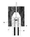
まず、図1のように金属芯線に被覆された内層管を準備する。また図1では便宜上、左側を基部とし、右側を先端部としている。 First, as shown in FIG. 1, an inner layer tube covered with a metal core wire is prepared. In FIG. 1, for the sake of convenience, the left side is the base and the right side is the tip.
この内層管の構成材料として、例えば、ポリテトラフルオロエチレン、テトラフルオロエチレン−パーフルオロアルキルビニルエーテル共重合体、テトラフルオロエチレン−ヘキサフルオロプロピレン共重合体、エチレン−テトラフルオロエチレン共重合体等のフッ素系樹脂、ポリプロピレン、ポリエチレン、エチレン−酢酸ビニル共重合体等のポリオレフィン、ポリアミド、ポリエチレンテレフタレート、ポリブチレンテレフタレート等のポリエステル、ポリウレタン、ポリ塩化ビニル、ポリスチレン系樹脂、ポリイミド等の樹脂、およびその混合物が挙げられるが、完成後の製品が内層管を通るガイドワイヤー等に対して優れた滑性を呈し、ガイドワイヤー追随性を伴う位置調整性を得る観点からは、ポリテトラフルオロエチレンまたはテトラフルオロエチレン−パーフルオロアルキルビニルエーテル共重合体で構成することが好ましい。 As a constituent material of the inner layer tube, for example, fluorine-based polytetrafluoroethylene, tetrafluoroethylene-perfluoroalkyl vinyl ether copolymer, tetrafluoroethylene-hexafluoropropylene copolymer, ethylene-tetrafluoroethylene copolymer, etc. Examples thereof include resins, polyolefins such as polypropylene, polyethylene, and ethylene-vinyl acetate copolymer, polyesters such as polyamide, polyethylene terephthalate, and polybutylene terephthalate, resins such as polyurethane, polyvinyl chloride, polystyrene resins, and polyimides, and mixtures thereof. However, from the viewpoint of obtaining excellent position-adjustability with a guide wire following property, the finished product exhibits excellent lubricity with respect to the guide wire or the like passing through the inner layer tube, or polytetrafluoroethylene or It is preferably made of a perfluoroalkyl vinyl ether copolymer - tetrafluoroethylene.
金属芯線に被覆された内層管は金属芯線に対して、充分な被着力を有していることが好ましい。さらに後の外層管を被覆する工程で、内層管と外層管との被着力を高める目的で、内層管表面に機械的な方法(軸方向とは直角な方向にサンドペーパーなどで内層管表面を擦るなどの手段)および/または化学的な方法(ナトリウムナフタリン+ジメチルエーテル等の薬剤の使用)、および/またはプラズマなどの電気的な方法でで凹凸を形成したり、表面改質したりしてもよい。 It is preferable that the inner layer tube covered with the metal core wire has a sufficient adherence to the metal core wire. Further, in the process of coating the outer tube, the inner tube surface is mechanically applied to the inner tube surface with sandpaper or the like in the direction perpendicular to the axial direction in order to increase the adhesion between the inner tube and the outer tube. The surface may be modified or surface-modified by means such as rubbing) and / or chemical methods (use of drugs such as sodium naphthalene + dimethyl ether) and / or electrical methods such as plasma. Good.
また、内層管の先端部はその外径が最先端部に向かうにしたがって次第に小さくなるよう、機械的、化学的な手段を以て加工してもよい。 Moreover, you may process the front-end | tip part of an inner-layer pipe | tube with a mechanical or chemical means so that the outer diameter may become small gradually as it goes to the most advanced part.
ついで図2のように断面が円形の線条体を線条体端部を線条体自身で巻き覆うことにより固定し、内層管の基部から線条体がほどけないようにして巻回を開始する。このような内層管に対して線条体がほどけず、緩まないように巻回することによって、空回りやズレなどの不具合が生じず、線条体を内層管に対して強く巻回することができる。 Next, as shown in Fig. 2, the linear member having a circular cross section is fixed by covering the end of the linear member with the linear member itself, and winding is started so that the linear member is not unwound from the base of the inner tube. To do. By winding so that the striate does not unravel and loosen around such an inner layer pipe, it is possible to wind the striate body tightly around the inner layer pipe without causing problems such as idling and displacement. it can.
さらに、図3のように先端部より基部にかけて線条体を巻回する。この巻回は等傾斜角度および/または等間隔、および/または連続的および/または段階的に傾斜角度および/または間隔が変化するものである。ここでの線条体の間隔はaで示し、線条体の傾斜角度はθで示されるものである。線条体の間隔aおよび線条体の傾斜角度θは、先端部に近いほどaが小さく、θは大きな角度をとることが好ましい。 Further, as shown in FIG. 3, the filament is wound from the tip to the base. In this winding, the inclination angle and / or the interval are changed, and / or the inclination angle and / or the interval change continuously and / or stepwise. The space | interval of a linear body here is shown by a, and the inclination-angle of a linear body is shown by (theta). As for the space | interval a of a filament, and the inclination | tilt angle (theta) of a filament, it is preferable that a is so small that it is near a front-end | tip part, and (theta) takes a big angle.
この補強層を構成する線条体の構成材料としては十分な補強効果が得られる程度の剛性を有するものであればいかなるものでもよく、例えば、ステンレス鋼、銅、タングステン、白金(Pt)、金、Pt−Ir合金、Pt−W合金、Pt−Ni合金、ニッケル、チタン、ピアノ線、Ni−Ti合金、Ni−Ti−Co合金、Ni−Al合金、Cu−Zn合金、Cu−Zn−X合金(例えば、X=Be、Si、Sn、Al、Ga)のような超弾性合金、アモルファス合金等の各種金属材料や、例えば、ポリエチレンテレフタレート(PET)、ポリブチレンテレフタレート(PBT)、ポリメチレンテレフタレート(PPT)のようなポリエステル、ポリエチレン、ポリプロピレンのようなポリオレフィン、硬質ポリ塩化ビニル、ポリアミド、ポリイミド、ポリスチレン、熱可塑性ポリウレタン、ポリカーボネート、ABS樹脂、アクリル樹脂、ポリメチルメタクリレート(PMMA)、ポリアセタール(PA)、ポリアリレート、ポリオキシメチレン(POM)、高張力ポリビニルアルコール、フッ素樹脂、ポリフッ化ビニリデン(PVdF)、ポリテトラフルオロエチレン、エチレン−酢酸ビニルケン化物(EVOH)、ポリスルホン、ポリエーテルスルホン、ポリエーテルケトン、ポリフェニレンオキサイド、ポリフェニレンスルフィド、ケブラーに代表される芳香族ポリアラミドなど、これらのうちのいずれかを含むポリマーアロイ、カーボンファイバー、グラスファイバーが挙げられる。これらの材料のうち、加工性、経済性、毒性がないこと等の理由からは、ステンレス鋼が好ましい。 Any material may be used as a constituent material of the striatum constituting the reinforcing layer as long as it has a rigidity sufficient to obtain a sufficient reinforcing effect. For example, stainless steel, copper, tungsten, platinum (Pt), gold , Pt—Ir alloy, Pt—W alloy, Pt—Ni alloy, nickel, titanium, piano wire, Ni—Ti alloy, Ni—Ti—Co alloy, Ni—Al alloy, Cu—Zn alloy, Cu—Zn—X Various metal materials such as superelastic alloys such as alloys (for example, X = Be, Si, Sn, Al, Ga) and amorphous alloys, for example, polyethylene terephthalate (PET), polybutylene terephthalate (PBT), polymethylene terephthalate Polyester such as (PPT), polyethylene, polyolefin such as polypropylene, rigid polyvinyl chloride, polyamide, Riimide, polystyrene, thermoplastic polyurethane, polycarbonate, ABS resin, acrylic resin, polymethyl methacrylate (PMMA), polyacetal (PA), polyarylate, polyoxymethylene (POM), high tension polyvinyl alcohol, fluororesin, polyvinylidene fluoride ( PVdF), polytetrafluoroethylene, ethylene-vinyl acetate saponified product (EVOH), polysulfone, polyethersulfone, polyetherketone, polyphenylene oxide, polyphenylene sulfide, aromatic polyaramid represented by Kevlar, etc. Examples thereof include polymer alloys, carbon fibers, and glass fibers. Of these materials, stainless steel is preferred for reasons such as workability, economy, and lack of toxicity.
なお、線条体は、上記材料等による単繊維または繊維の集合体(例えば単繊維を縒ったもの)のいずれでもよい。また、線条体の太さは、その構成材料との関係で必要かつ十分な補強効果が得られる程度のものとされ、例えば上記金属材料による場合は、直径5〜50μm程度とするのが好ましい。なお、線条体は、単一で用いても、複数本を束ねた状態で用いてもよい。 The filament may be either a single fiber or an aggregate of fibers (for example, a single fiber). Further, the thickness of the striatum is such that a necessary and sufficient reinforcing effect is obtained in relation to its constituent materials. For example, in the case of using the above metal material, the diameter is preferably about 5 to 50 μm. . In addition, a linear body may be used by single, or may be used in the state which bundled multiple pieces.
ここで、十分な補強効果が得られる程度の剛性を有する線条体は、同時に弾性を有することがあるので、この終端は巻回がほどけるのを防止するためにアルミなどの塑性金属素線を巻回して固定した後に線条体を切断したり、シュリンクチューブを被覆後、加熱して収縮せしめ、固定した後に線条体を切断することが好ましい。 Here, since the wire body having a rigidity sufficient to obtain a sufficient reinforcing effect may have elasticity at the same time, the end of the wire is made of a plastic metal wire such as aluminum in order to prevent unwinding. It is preferable to cut the striated body after it is wound and fixed, or after the shrink tube is coated, heated and contracted, and fixed.
かかる補強層を形成するための線条体の巻回方法は、内層管の外周に線条体供給部から供給される線条体を螺旋状に巻回し、前記内層管と前記線状体供給部の相対的位置を左右に変化させること、前記内層管と前記線条体供給部との相対移動速度および/または相対回転速度を変えることにより、カテーテルチューブの軸方向に沿って、前記線条体のカテーテルチューブ軸に対する傾斜角度および/または間隔を連続的および/または段階的に変化させることによってなされる。 The method of winding the filament for forming the reinforcing layer is to spirally wind the filament supplied from the filament supply unit on the outer periphery of the inner tube, and supply the inner tube and the linear member. By changing the relative position of the part to the left and right, and changing the relative moving speed and / or the relative rotational speed of the inner layer tube and the striate body supply part, the striate is along the axial direction of the catheter tube. This is done by changing the tilt angle and / or spacing of the body relative to the catheter tube axis continuously and / or stepwise.
また、上記の線条体の巻回は、線条体の供給部を固定し金属芯金に被覆された内層管を回転させることによっても達成し得るし、逆に金属芯金に被覆された内層管を固定し線条体の供給部を回転させることによっても達成しうる。さらに、巻回を行う際、内層管に巻回された線条体のずれを防止する観点から、線条体と内層管の間には一定の張力が保持され続けることが好ましい。 Further, the winding of the above-mentioned wire rod can be achieved by fixing the supply portion of the wire rod and rotating the inner tube covered with the metal core, or conversely, the wire core covered This can also be achieved by fixing the inner layer tube and rotating the supply portion of the striate body. Furthermore, when performing winding, it is preferable to maintain a constant tension between the linear body and the inner layer pipe from the viewpoint of preventing displacement of the linear body wound around the inner layer pipe.
続いて図4のようにX線不透過性のマーカーを配する。補強材層を形成する線条体が既にX線不透過性を有する場合は、その先端部分をX線不透過性のマーカーとすることができる。また、補強材層とは別にX線不透過性のマーカーを設置する際には、位置としては補強材層に接して、その材質と形状、手段については、白金(Pt)、Pt−Ir合金、Pt−W合金、Pt−Ni合金、金、銀などの素線を巻き付けたり、白金(Pt)、金、Pt−Ir合金、Pt−W合金、Pt−Ni合金、銀などの管を配置したり、白金(Pt)、Pt−Ir合金、Pt−W合金、Pt−Ni合金、金、銀などの板を円筒形にして配置したり、硫酸バリウム、酸化ビスマス、次炭酸ビスマス、タングステン酸ビスマス、ビスマス−オキシクロライド等の粉体を混練した樹脂チューブを配置してもよい。 Subsequently, a radiopaque marker is arranged as shown in FIG. When the striatum forming the reinforcing material layer already has radiopacity, the tip portion can be used as a radiopaque marker. When a radiopaque marker is installed separately from the reinforcing material layer, the position is in contact with the reinforcing material layer, and the material, shape and means thereof are platinum (Pt), Pt-Ir alloy. , Pt-W alloy, Pt-Ni alloy, gold, silver or other wire is wound, or platinum (Pt), gold, Pt-Ir alloy, Pt-W alloy, Pt-Ni alloy, silver, etc. are arranged Or platinum (Pt), Pt—Ir alloy, Pt—W alloy, Pt—Ni alloy, gold, silver, etc. are arranged in a cylindrical shape, barium sulfate, bismuth oxide, bismuth subcarbonate, tungstic acid A resin tube in which powders such as bismuth and bismuth-oxychloride are kneaded may be disposed.
次いで補強材層を形成する線条体がX線不透過性を有しないものを使用する場合には、図5のようにX線不透過性のマーカーを固定するために、これをかしめるか、および/または前記内層管と接着するか、前記補強材層と接着、溶着、溶接するか、および/またはX線不透過性のマーカーに接してアルミなどの塑性金属素線(丸線または角線)を巻回して固定し構造体を形成することが好ましい。 Next, when using a wire body that does not have radiopacity as the striation body forming the reinforcing material layer, is it caulked to fix the radiopaque marker as shown in FIG. And / or bonded to the inner layer tube, bonded to the reinforcing material layer, welded, welded, and / or a plastic metal wire such as aluminum (round line or corner in contact with a radiopaque marker) It is preferable to form a structure by winding and fixing the wire.
さらに図6のように外層管を基部から先端部にかけてそれを形成する樹脂管が一段階以上のショアD硬度の有するものを配置する。図6では四種類のショアD硬度を有するものを密接させて配置した状態を示したが、基部から先端部にかけて徐々にショアD硬度が低くなるように配置する必要がある。ショアD硬度は20〜80程度であるものが好適に用いられる。一種類のショアD硬度を有する外層管のみを配置する際には、前記一種類のショアD硬度を有する外層管を複数本に分割して密接させて配置してもよい。 Further, as shown in FIG. 6, the outer layer tube is arranged from the base portion to the tip portion, and the resin tube forming the outer tube has one or more stages of Shore D hardness. Although FIG. 6 shows a state in which four types of Shore D hardness are closely arranged, it is necessary to arrange the Shore D hardness to gradually decrease from the base to the tip. Those having a Shore D hardness of about 20 to 80 are preferably used. When only the outer layer pipe having one type of Shore D hardness is arranged, the outer layer pipe having one type of Shore D hardness may be divided into a plurality of pieces and arranged closely.
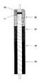
このように前記補強材の巻回の長さと間隔、傾斜角度と、ショアDの異なる樹脂管の配置とその長さの設定とが相まって、剛性と柔軟性の傾斜制御の高い調節自由度、多様なアクセス経路に応じた調子設定性が発揮される。ここでいう調子とは図7のように先端部の高い柔軟性を有する領域の位置が異なっていることである。この図7において直線部分は先端部に比較して剛性は高いが柔軟性も同時に確保されていることを示している。多様な調子を設定できることによって、図7において、1号調に近いほど先端部の状況をダイレクトに感度よく伝えると同時にトルクの伝達能が高く、5号調に近いほど複雑な経路への侵入、深奥部への到達が行いやすくなるなどの使用上の事項に加え、多様な患部に対して施術者の手術方法の意図が反映され、かつ選択できるといった利点がある。 In this way, the length and interval of winding of the reinforcing material, the inclination angle, the arrangement of the resin pipes with different Shore D and the setting of the length are combined, and the degree of freedom of adjustment of the inclination control of rigidity and flexibility is high and various. Tone setting according to various access routes is demonstrated. The term “tone” here means that the position of the highly flexible region at the tip is different as shown in FIG. In FIG. 7, the straight line portion has higher rigidity than the tip portion, but shows that flexibility is secured at the same time. By being able to set various tones, in Fig. 7, the closer to No. 1 tone, the more sensitive the torque of the tip part is, and at the same time the higher the torque transmission capability, the closer to No. 5 tone, In addition to the matter of use such as easy access to the deep part, there is an advantage that the intention of the surgeon's surgical method is reflected and selected for various affected parts.
外層管を形成する樹脂管の材質としてはポリアミドエラストマー、ポリエステルエラストマー、ポリウレタンエラストマー、ポリスチレンエラストマー、フッ素系エラストマー、シリコーンゴム、ラテックスゴム等の各種エラストマー、またはこれらのうちの2以上を組み合わせたものが使用可能である。 As the material of the resin tube forming the outer tube, various elastomers such as polyamide elastomer, polyester elastomer, polyurethane elastomer, polystyrene elastomer, fluorine elastomer, silicone rubber, latex rubber, or a combination of two or more of these are used. Is possible.
ここで、ポリアミドエラストマーとは、例えば、ナイロン6、ナイロン64、ナイロン66、ナイロン610、ナイロン612、ナイロン46、ナイロン9、ナイロン11、ナイロン12、N−アルコキシメチル変性ナイロン、ヘキサメチレンジアミン−イソフタル酸縮重合体、メタキシロイルジアミン−アジピン酸縮重合体のような各種脂肪族または芳香族ポリアミドをハードセグメントとし、ポリエステル、ポリエーテル等のポリマーをソフトセグメントとするブロック共重合体が代表的であり、その他、前記ポリアミドと柔軟性に富む樹脂とのポリマーアロイ(ポリマーブレンド、グラフト重合、ランダム重合等)や、前記ポリアミドを可塑剤等で軟質化したもの、さらには、これらの混合物をも含む概念である。 Here, the polyamide elastomer is, for example,
また、ポリエステルエラストマーとは、ポリエチレンテレフタレート、ポリブチレンテレフタレート等の飽和ポリエステルと、ポリエーテルまたはポリエステルとのブロック共重合体が代表的であり、その他、これらのポリマーアロイや前記飽和ポリエステルを可塑剤等で軟質化したもの、さらには、これらの混合物をも含む概念である。 The polyester elastomer is typically a block copolymer of a saturated polyester such as polyethylene terephthalate or polybutylene terephthalate and a polyether or polyester. In addition, the polymer alloy or the saturated polyester may be used as a plasticizer. It is a concept that includes a softened material and a mixture thereof.
好適に用いられる材料としては、その加工性、柔軟性の観点からポリアミドエラストマーが好ましく、例えばelf atochem社製のPEBAXなどがその代表として挙げられる。 As a material suitably used, a polyamide elastomer is preferable from the viewpoint of processability and flexibility. For example, PEBAX manufactured by elf atochem is representative.
続いて、外層管の内周面が内層管の外周面、および補強層を形成する線条体、加えて隣接しショアD硬度の異なる外層管同士を密着接合し、一体化させる方法としては、たとえば次のものが挙げられる。図8のように構成体全体を、加熱することによりその径が縮小する性質を有するシュリンクチューブで覆い、ヒーターで加熱融着させるか、および/または高周波電磁波を加えて加熱融着、一体化する方法が好適に用いうる方法である。これにより内層管、補強材層、外層管が相互に密着一体化し、さらに軟質の外層管最先端部が樹脂の軟化とシュリンクチューブの収縮によりアール状に賦形される。また、この賦形により後述の金属芯金引き抜き時に内層管の内外径が小さくなる場合もある。 Subsequently, the inner peripheral surface of the outer layer tube is the outer peripheral surface of the inner layer tube, and the striatum forming the reinforcing layer, in addition, the adjacent outer layer tubes having different Shore D hardnesses are closely bonded and integrated, For example: As shown in FIG. 8, the entire structure is covered with a shrink tube having the property of reducing its diameter when heated and heated and fused with a heater and / or heated and fused and integrated by applying high-frequency electromagnetic waves. The method can be suitably used. As a result, the inner layer tube, the reinforcing material layer, and the outer layer tube are tightly integrated with each other, and the leading end portion of the soft outer layer tube is shaped like a round shape by the softening of the resin and the shrinkage of the shrink tube. In addition, due to this shaping, the inner and outer diameters of the inner tube may be reduced when the metal core is pulled out as described later.
この外層管形成に際しては図6のように外層管を基部から先端部にかけてそれを形成する樹脂管が一段階以上のショアD硬度の有するものを配置し、および該樹脂管のショアD硬度を多段階とする際には該ショアD硬度が基部から先端部にかけて次第に小さくなるように配置した上で、その全体を電熱ヒーターおよび/または高周波誘導により加熱できる金型内を通過させることにより、内層管、補強材層、外層管を一体化せしめる方法をとることができる(図示せず)。 When forming this outer layer tube, as shown in FIG. 6, the resin tube forming the outer layer tube from the base to the tip is arranged with one or more stages of Shore D hardness, and the resin tube has a large Shore D hardness. When setting the stage, the Shore D hardness is arranged so as to gradually decrease from the base portion to the tip portion, and then the whole is passed through a mold that can be heated by an electric heater and / or high-frequency induction, thereby forming an inner tube The reinforcing material layer and the outer layer tube can be integrated (not shown).
また、図5の状態にある構造体にショアD硬度が一段階以上となるように外層管を被覆押出し、およびショアD硬度を多段階とする際には該ショアD硬度が基部から先端部にかけて次第に小さくなるように外層管を被覆押出して形成し、内層管、補強材層、外層管を一体化せしめる方法を採ることもできる(図示せず)。この際、多段階、たとえば3段階のショアD硬度の樹脂を被覆する際には、一つの押出金型に3台の押出機をつなぎ、目標外径になるように制御しながら、順次この3台の押出機を運転・停止させて外層管を形成することができる。また、弁機構を有する金型に3台の押出機をつなぎ、連続的に押出をしながら、順次ショアD硬度の異なる樹脂を押出流路内に導入・排出を切り替えながら被覆して外層管を形成することもできる。このように被覆押出を行う際には、図5の状態にある構造体の金属芯金部分を多数本、直列に溶接などの方法で連結してもよい。 Further, when the outer layer tube is coated and extruded to the structure in the state of FIG. 5 so that the Shore D hardness becomes one step or more, and when the Shore D hardness is made multi-step, the Shore D hardness extends from the base portion to the tip portion. It is also possible to adopt a method in which the outer layer tube is formed by covering and extruding so as to gradually become smaller, and the inner layer tube, the reinforcing material layer, and the outer layer tube are integrated (not shown). At this time, when coating a resin having a multi-stage, for example, three-stage Shore D hardness, three extruders are connected to one extrusion mold and controlled so as to achieve a target outer diameter, and the three are sequentially applied. The outer layer tube can be formed by operating and stopping the extruder of the table. In addition, three extruders are connected to a mold having a valve mechanism, and while continuously extruding, a resin having a different Shore D hardness is sequentially applied to the extrusion flow channel while covering and switching the outer tube. It can also be formed. Thus, when performing coating extrusion, you may connect many metal core metal parts of the structure in the state of FIG. 5 by methods, such as welding, in series.
さらに外層管最先端部をテーパー形状またはテーパー状に成形に形成する必要があるときには図9のように内面がポリテトラフルオロエチレンに代表される非着性コーティングで被覆され、ヒーターで加熱できるような金型を用意し、図10のように該金型内に外層管最先端部を挿入して、その形状をテーパー形状とすることができる。図9、10では図8のシュリンクチューブが被覆された状態での成形となっているが、上述した内層管、補強材層、外層管を電熱ヒータおよび/または高周波誘導により加熱できる金型内を通過させて一体化せしめたもの、または図5の状態にある構造体にショアD硬度が一段階以上となるように外層管を被覆押出し、およびショアD硬度を多段階とする際には該ショアD硬度が基部から先端部にかけて次第に小さくなるように外層管を被覆押出して形成し、内層管、補強材層、外層管を一体化せしめたものの外層管最先端部を図9のような金型を用いてテーパー形状またはテーパー状に成形に賦形することも可能である。 Further, when it is necessary to form the tip of the outer layer tube into a taper shape or a taper shape, the inner surface is coated with a non-stick coating typified by polytetrafluoroethylene as shown in FIG. 9 and can be heated with a heater. A mold can be prepared and the outermost tube outermost portion can be inserted into the mold as shown in FIG. In FIGS. 9 and 10, the shrink tube shown in FIG. 8 is coated. However, the inner layer pipe, the reinforcing material layer, and the outer layer pipe described above are heated inside the mold that can be heated by an electric heater and / or high frequency induction. When the outer layer tube is coated and extruded so that the Shore D hardness becomes one step or more to the structure that is passed through and integrated, or the structure in the state shown in FIG. The outer layer tube is formed by covering and extruding the outer layer tube so that the D hardness gradually decreases from the base to the tip, and the inner layer tube, the reinforcing material layer, and the outer layer tube are integrated into the die as shown in FIG. It is also possible to form into a tapered shape or a tapered shape using
次いで図11のようにシュリンクチューブを剥がし、図12のように金属芯金を引き抜くとカテーテルチューブが得られる。ここで基部端はその整形のために高速回転する円盤状のダイヤモンドカッターなどの手段で内層、補強層、外層を切断し、基部端断面を単一平面に仕上げることができる(図示しない)。 Next, the shrink tube is peeled off as shown in FIG. 11 and the metal core is pulled out as shown in FIG. 12 to obtain a catheter tube. Here, the base end can be cut into an inner layer, a reinforcing layer, and an outer layer by means such as a disk-shaped diamond cutter that rotates at high speed for shaping, and the base end cross section can be finished into a single plane (not shown).
さらにここでは図示しないがカテーテルチューブ表面を親水性(または水溶性)高分子物質で覆われていることが好ましい。これにより、カテーテルチューブの外表面が血液または生理食塩水等に接触したときに、摩擦係数が減少して潤滑性が付与され、カテーテルチューブの摺動性が一段と向上し、その結果、押し込み性、追随性、耐キンク性および安全性が一段と高まる。親水性高分子物質としては、たとえば以下のような天然または合成の高分子物質、あるいはその誘導体が挙げられる。特に、セルロース系高分子物質(例えば、ヒドロキシプロピルセルロース)、ポリエチレンオキサイド系高分子物質(ポリエチレングリコール)、無水マレイン酸系高分子物質(例えば、メチルビニルエーテル無水マレイン酸共重合体のような無水マレイン酸共重合体)、アクリルアミド系高分子物質(例えば、ポリアクリルアミド)、水溶性ナイロンは、低い摩擦係数が安定的に得られるので好ましい。 Further, although not shown here, the catheter tube surface is preferably covered with a hydrophilic (or water-soluble) polymer substance. As a result, when the outer surface of the catheter tube comes into contact with blood or saline, the friction coefficient is reduced and lubricity is imparted, and the slidability of the catheter tube is further improved. Followability, kink resistance and safety are further enhanced. Examples of the hydrophilic polymer substance include the following natural or synthetic polymer substances or derivatives thereof. In particular, cellulosic polymer materials (eg, hydroxypropyl cellulose), polyethylene oxide polymer materials (polyethylene glycol), maleic anhydride polymer materials (eg, maleic anhydride such as methyl vinyl ether maleic anhydride copolymer) Copolymers), acrylamide polymer substances (for example, polyacrylamide), and water-soluble nylon are preferable because a low coefficient of friction can be stably obtained.
加えてここでは図示しないが、基部端に適切な形状のハブを取り付けて、目的とする最良の形態の医療用カテーテルチューブが得られる。 In addition, although not shown here, a hub having an appropriate shape is attached to the base end to obtain the medical catheter tube of the best form of interest.
なお、その使用に際しては上述のまま使用してもよいし、必要があるならば、予め医療用カテーテルチューブの一部をヒーターなどで加熱し、湾曲部を形成しておくこともできる。 In addition, when using it, it may be used as described above, and if necessary, a part of the medical catheter tube may be heated with a heater or the like in advance to form a curved portion.
以下、本発明の医療用カテーテルチューブの具体例について説明する。 Hereinafter, specific examples of the medical catheter tube of the present invention will be described.
(実施例1)
図1〜8、11、12にに示したように、医療用カテーテルチューブを製造した。なお補強材層の製造は巻回機を用いて作成した。外層管はシュリンクチューブを用いて一体化させた。
カテーテルチューブ全体長:カテーテル先端部より1000mm。
内層管と外層管のみからなる部分:先端より0mm〜1mm、領域長さ1.0mm
マーカー部分:先端より1mm〜2mm、領域長さ1.0mm
補強材の直径:13μm、補強材の材質:SUS304製
補強材の巻回ピッチと長さ:
先端より2mm〜4mm:巻きピッチ100μm、領域長さ2mm
先端より4mm〜6mm:巻きピッチ120μm、領域長さ2mm
先端より6mm〜8mm:巻きピッチ150μm、領域長さ2mm
先端より8mm〜10mm:巻きピッチ180μm、領域長さ2mm
先端より10mm〜60mm:巻きピッチ200μm、領域長さ50mm
先端より60mm〜120mm:巻きピッチ220μm、領域長さ60mm
先端より120mm〜180mm:巻きピッチ250μm、領域長さ60mm
先端より180mm〜300mm:巻きピッチ300μm、領域長さ120mm
先端より300mm〜1000mm:巻きピッチ350μm、領域長さ700mm
内層管の内直径:0.42mm
内層管の外直径:0.47mm
内層管を構成する材料:ポリテトラフルオロエチレン
カテーテルチューブ完成後の外層管外直径:0.57mm
外層管を構成する材料と長さ
先端部0〜100mmの領域:elf atochem社製Pebax2533(ショアD硬度25D)
基端部より100mm〜300mmの領域:elf atochem社製Pebax4033(ショアD硬度40D)
基端部より300mm〜1000mmの領域:elf atochem社製Pebax6333(ショアD硬度63D)
このように構成したカテーテルチューブの基端部にハブを取り付けて、先端部より5mmの位置から直径3mmの金属棒に5回巻き付けて固定し、基端部にハブを取り付けそのカテーテルチューブ全体を37℃の体温付近に設定した恒温下の温水中に没し、ハブより注射器を用いて食紅で染色した生理食塩水を0.2cc/minの速度で注入した。Example 1
As shown in FIGS. 1-8, 11, and 12, a medical catheter tube was manufactured. The reinforcing material layer was produced using a winding machine. The outer layer tube was integrated using a shrink tube.
Total length of catheter tube: 1000 mm from the distal end of the catheter.
Portion consisting only of inner layer tube and outer layer tube: 0mm to 1mm from the tip, region length 1.0mm
Marker part: 1 mm to 2 mm from the tip, area length 1.0 mm
Diameter of reinforcing material: 13 μm, Material of reinforcing material: Winding pitch and length of reinforcing material made of SUS304:
2 mm to 4 mm from the tip: winding pitch 100 μm,
4 mm to 6 mm from the tip: winding pitch 120 μm,
6 mm to 8 mm from the tip: winding pitch 150 μm,
8 mm to 10 mm from the tip: winding pitch 180 μm,
10 mm to 60 mm from the tip: winding pitch 200 μm, region length 50 mm
60 mm to 120 mm from the tip: winding pitch 220 μm, region length 60 mm
120 mm to 180 mm from the tip: winding pitch 250 μm, region length 60 mm
180 mm to 300 mm from tip: winding pitch 300 μm, region length 120 mm
300 mm to 1000 mm from the tip: winding pitch 350 μm, region length 700 mm
Inner diameter of inner tube: 0.42mm
Outer diameter of inner layer tube: 0.47mm
Material composing inner layer tube: Outer diameter of outer layer tube after completion of polytetrafluoroethylene catheter tube: 0.57 mm
Material constituting the outer tube and length 0 to 100 mm: Pebax 2533 manufactured by elf atochem (Shore D hardness 25D)
Area from 100 mm to 300 mm from the base end: Pebax 4033 (Shore D hardness 40D) manufactured by elf atochem
300 mm to 1000 mm region from the base end: Pebax 6333 manufactured by elf atochem (Shore D hardness 63D)
A hub is attached to the proximal end portion of the catheter tube configured as described above, and is fixed by winding it around a metal rod having a diameter of 3 mm from a
この結果、生理食塩水は連続的に安定して先端部より放出されて、温水中から取り出した際にも5回巻き付け部分にはキンクが生じていないことが確認された。 As a result, it was confirmed that the physiological saline was continuously and stably released from the tip portion, and even when taken out from the warm water, no kinks were generated in the portion wound five times.
(実施例2)
図1〜8、11、12にに示したように、医療用カテーテルチューブを製造した。なお補強材層の製造は巻回機を用いて作成した。外層管はシュリンクチューブを用いて一体化させた。
カテーテルチューブ全体長:カテーテル先端部より1300mm。
内層管と外層管のみからなる部分:先端より0mm〜1mm、領域長さ1.0mm
マーカー部分:先端より1mm〜2mm、領域長さ1.0mm
補強材の直径:13μm、補強材の材質:SUS304製
補強材の巻回ピッチと長さ:
先端より2mm〜4mm:巻きピッチ90μm、領域長さ2mm
先端より4mm〜6mm:巻きピッチ100μm、領域長さ2mm
先端より6mm〜8mm:巻きピッチ120μm、領域長さ2mm
先端より8mm〜10mm:巻きピッチ150μm、領域長さ2mm
先端より10mm〜60mm:巻きピッチ180μm、領域長さ50mm
先端より60mm〜120mm:巻きピッチ200μm、領域長さ60mm
先端より120mm〜180mm:巻きピッチ250μm、領域長さ60mm
先端より180mm〜300mm:巻きピッチ300μm、領域長さ120mm
先端より300mm〜1300mm:巻きピッチ350μm、領域長さ700mm
内層管の内直径:0.45mm
内層管の外直径:0.49mm
内層管を構成する材料:ポリテトラフルオロエチレン
カテーテルチューブ完成後の外層管外直径:0.59mm
外層管を構成する材料と長さ
先端部0〜100mmの領域:elf atochem社製Pebax2533(ショアD硬度25D)
基端部より100mm〜300mmの領域:elf atochem社製Pebax4033(ショアD硬度40D)
基端部より300mm〜1300mmの領域:elf atochem社製Pebax6333(ショアD硬度63D)
このように構成したカテーテルチューブの基端部にハブを取り付けて、先端部より5mmの位置から直径3mmの金属棒に5回巻き付けて固定し、基端部にハブを取り付けそのカテーテルチューブ全体を37℃の体温付近に設定した恒温下の温水中に没し、ハブより注射器を用いて食紅で染色した生理食塩水を0.2cc/minの速度で注入した。(Example 2)
As shown in FIGS. 1-8, 11, and 12, a medical catheter tube was manufactured. The reinforcing material layer was produced using a winding machine. The outer layer tube was integrated using a shrink tube.
Total length of catheter tube: 1300 mm from the distal end of the catheter.
Portion consisting only of inner layer tube and outer layer tube: 0mm to 1mm from the tip, region length 1.0mm
Marker part: 1 mm to 2 mm from the tip, area length 1.0 mm
Diameter of reinforcing material: 13 μm, Material of reinforcing material: Winding pitch and length of reinforcing material made of SUS304:
2 mm to 4 mm from the tip: winding pitch 90 μm,
4 mm to 6 mm from the tip: winding pitch 100 μm,
6 mm to 8 mm from the tip: winding pitch 120 μm,
8 mm to 10 mm from the tip: winding pitch 150 μm,
10 mm to 60 mm from the tip: winding pitch 180 μm, region length 50 mm
60 mm to 120 mm from the tip: winding pitch 200 μm, region length 60 mm
120 mm to 180 mm from the tip: winding pitch 250 μm, region length 60 mm
180 mm to 300 mm from the tip: winding pitch 300 μm, region length 120 mm
300 mm to 1300 mm from the tip: winding pitch 350 μm, region length 700 mm
Inner diameter of inner tube: 0.45mm
Outer diameter of inner layer tube: 0.49mm
Material constituting inner layer tube: outer diameter of outer layer tube after completion of polytetrafluoroethylene catheter tube: 0.59 mm
Material constituting the outer tube and length 0 to 100 mm region: Pebax 2533 manufactured by elf atochem (Shore D hardness 25D)
Area from 100 mm to 300 mm from the base end: Pebax 4033 (Shore D hardness 40D) manufactured by elf atochem
300 mm to 1300 mm region from the base end: Pebax 6333 (Shore D hardness 63D) manufactured by elf atochem
A hub is attached to the proximal end portion of the catheter tube configured as described above, and is fixed by winding it around a metal rod having a diameter of 3 mm from a
この結果、生理食塩水は連続的に安定して先端部より放出されて、温水中から取り出した際にも5回巻き付け部分にはキンクが生じていないことが確認された。 As a result, it was confirmed that the physiological saline was continuously and stably released from the tip portion, and even when taken out from the warm water, no kinks were generated in the portion wound five times.
(比較例1)
実施例1で内層管、外層管の構成は変えずに線条体の巻回による補強材層を設けないチューブを作成した。(Comparative Example 1)
In Example 1, the inner layer tube and the outer layer tube were not changed in configuration, and a tube in which a reinforcing material layer was not provided by winding the filament was prepared.
このカテーテルチューブの基端部にハブを取り付けて、先端部より5mmの位置から直径3mmの金属棒に5回巻き付けて固定し、基端部にハブを取り付けそのカテーテルチューブ全体を37℃の体温付近に設定した恒温下の温水中に没し、ハブより注射器を用いて食紅で染色した生理食塩水を0.2cc/minの速度で注入した。 Attach a hub to the proximal end of this catheter tube, wrap it around a metal rod with a diameter of 3 mm from a
この結果、生理食塩水は断続的に不安定にしか先端部より放出されず、温水中から取り出した際にも5回巻き付け部分にはキンクが生じいることが確認された。 As a result, it was confirmed that the physiological saline was intermittently released from the tip only unstablely, and even when taken out from the warm water, kinks were generated at the portion wound five times.
(比較例2)
実施例2で内層管、外層管の構成は変えずに線条体の巻回による補強材層を設けないチューブを作成した。(Comparative Example 2)
In Example 2, the inner layer tube and the outer layer tube were not changed in configuration, and a tube without a reinforcing material layer formed by winding the filament was prepared.
このカテーテルチューブの基端部にハブを取り付けて、先端部より5mmの位置から直径5mmの金属棒に5回巻き付けて固定し、基端部にハブを取り付けそのカテーテルチューブ全体を37℃の体温付近に設定した恒温下の温水中に没し、ハブより注射器を用いて食紅で染色した生理食塩水を0.8cc/minの速度で注入した。 A hub is attached to the proximal end of this catheter tube, and it is fixed by wrapping around a metal rod with a diameter of 5 mm from a
この結果、生理食塩水は断続的に不安定にしか先端部より放出されず、温水中から取り出した際にも5回巻き付け部分にはキンクが生じいることが確認された。 As a result, it was confirmed that the physiological saline was intermittently released from the tip only unstablely, and even when taken out from the warm water, kinks were generated at the portion wound five times.
a 線条体の間隔
θ 線条体の傾斜角度
1 X線不透過性のマーカー
2 X線不透過性のマーカーを固定するためのアルミなどの塑性金属素線の巻回部
3 構成する外層管のうち最高ショアD硬度を有する外層樹脂管
4 構成する外層管のうち高ショアD硬度を有する外層樹脂管
5 構成する外層管のうち低ショアD硬度を有する外層樹脂管
6 構成する外層管のうち最低ショアD硬度を有する外層樹脂管a Streak interval θ Inclination angle of the
Claims (14)
Translated fromJapanese該カテーテルチューブが基部と先端部を有し、
線条体を内層管上に螺旋状を以て基部から先端部にかけて巻回して補強層を形成し、
該内層管先端部における線条体の巻回開始端部は該線条体を巻き覆うことによって、線条体を内層管に固定し、
外層管は基部から先端部にかけてそれを形成する樹脂管が一段階以上のショアD硬度を有するものが配され、
補強材層が存在しない先端部を有し、
該補強材層と該外層管の存在により、基部から先端部にかけての曲げ剛性が段階的または連続的に小さくなるように構成したことを特徴とする
医療用カテーテルチューブ。Inner layer tube made of a resin tube that exhibits lubricity and flexibility, and a reinforcing material obtained by winding a linear body on the inner layer tube that adjusts flexibility and further imparts kink resistance, torque transmission, pushability, etc. A medical catheter tube in which an outer layer pipe made of a resin pipe covering a layer and a reinforcing material layer and having flexibility is integrated,
The catheter tube has a base and a distal end;
A reinforcing layer is formed by winding the striated body from the base to the tip with a spiral on the inner layer pipe,
The winding start end of the striate body at the tip of the inner layer pipe covers the striate, thereby fixing the striatum to the inner layer pipe,
The outer tube is arranged such that the resin tube forming it from the base to the tip has a Shore D hardness of one or more stages,
It has a tip where no reinforcing material layer exists,
A medical catheter tube characterized in that bending rigidity from a base portion to a distal end portion decreases stepwise or continuously due to the presence of the reinforcing material layer and the outer layer tube.
Priority Applications (1)
| Application Number | Priority Date | Filing Date | Title |
|---|---|---|---|
| JP2004218565AJP2006034578A (en) | 2004-07-27 | 2004-07-27 | Catheter tube for medical use and manufacturing method therefor |
Applications Claiming Priority (1)
| Application Number | Priority Date | Filing Date | Title |
|---|---|---|---|
| JP2004218565AJP2006034578A (en) | 2004-07-27 | 2004-07-27 | Catheter tube for medical use and manufacturing method therefor |
Publications (1)
| Publication Number | Publication Date |
|---|---|
| JP2006034578Atrue JP2006034578A (en) | 2006-02-09 |
Family
ID=35900206
Family Applications (1)
| Application Number | Title | Priority Date | Filing Date |
|---|---|---|---|
| JP2004218565APendingJP2006034578A (en) | 2004-07-27 | 2004-07-27 | Catheter tube for medical use and manufacturing method therefor |
Country Status (1)
| Country | Link |
|---|---|
| JP (1) | JP2006034578A (en) |
Cited By (4)
| Publication number | Priority date | Publication date | Assignee | Title |
|---|---|---|---|---|
| JP2011010787A (en)* | 2009-07-01 | 2011-01-20 | Kaneka Corp | Catheter |
| CN109999317A (en)* | 2019-05-21 | 2019-07-12 | 心凯诺医疗科技(上海)有限公司 | A kind of conduit and intervention device of adjustable hardness |
| CN113476709A (en)* | 2021-06-25 | 2021-10-08 | 浙江大学 | Suction type bite-block for tracheal intubation |
| US12186495B2 (en) | 2018-10-11 | 2025-01-07 | Asahi Intecc Co., Ltd. | Medical multi-lumen tube and method for producing the same |
- 2004
- 2004-07-27JPJP2004218565Apatent/JP2006034578A/enactivePending
Cited By (5)
| Publication number | Priority date | Publication date | Assignee | Title |
|---|---|---|---|---|
| JP2011010787A (en)* | 2009-07-01 | 2011-01-20 | Kaneka Corp | Catheter |
| US12186495B2 (en) | 2018-10-11 | 2025-01-07 | Asahi Intecc Co., Ltd. | Medical multi-lumen tube and method for producing the same |
| CN109999317A (en)* | 2019-05-21 | 2019-07-12 | 心凯诺医疗科技(上海)有限公司 | A kind of conduit and intervention device of adjustable hardness |
| CN113476709A (en)* | 2021-06-25 | 2021-10-08 | 浙江大学 | Suction type bite-block for tracheal intubation |
| CN113476709B (en)* | 2021-06-25 | 2023-08-08 | 浙江大学 | Tooth pad for suction type tracheal cannula |
Similar Documents
| Publication | Publication Date | Title |
|---|---|---|
| JP4924418B2 (en) | Medical catheter tube and manufacturing method thereof | |
| JP4501938B2 (en) | Medical catheter tube and manufacturing method thereof | |
| JP4553010B2 (en) | Medical catheter tube and manufacturing method thereof | |
| JPWO2006016481A1 (en) | Medical catheter tube and manufacturing method thereof | |
| JP4854458B2 (en) | Medical multi-lumen tube | |
| JP4647299B2 (en) | Medical catheter tube and manufacturing method thereof | |
| JP5233156B2 (en) | Medical catheter tube | |
| JPWO2008056625A1 (en) | Medical catheter tube | |
| JP2006034347A (en) | Catheter tube for medical use and manufacturing method therefor | |
| JP2005312633A (en) | Medical catheter tube and method of manufacturing same | |
| JP2006051080A (en) | Medical catheter tube and method for manufacturing the same | |
| JP2006051081A (en) | Medical catheter tube and method for manufacturing the same | |
| JP2006218085A (en) | Medical catheter tube and its manufacturing method | |
| JP2006288943A (en) | Medical catheter tube, and its manufacturing method | |
| JP2006034578A (en) | Catheter tube for medical use and manufacturing method therefor | |
| JP2007296030A (en) | Medical catheter tube and its manufacturing method | |
| JP2007029120A (en) | Medical catheter tube and its manufacturing method | |
| JP4777132B2 (en) | Medical catheter tube and manufacturing method thereof | |
| JP2005334396A (en) | Medical catheter tube and method for manufacturing it | |
| JP2006288944A (en) | Catheter tube for medical use, and its manufacturing method | |
| JP4397319B2 (en) | Microcatheter manufacturing method and microcatheter | |
| JP2005334242A (en) | Medical catheter tube and method for manufacturing it | |
| JP2005319195A (en) | Medical catheter tube and method of manufacturing the same | |
| JP2006158878A (en) | Catheter tube for medical use and manufacturing method thereof | |
| JP2014100327A (en) | Catheter tube manufacturing method |