JP2006033570A - Image generating device - Google Patents
Image generating deviceDownload PDFInfo
- Publication number
- JP2006033570A JP2006033570AJP2004211371AJP2004211371AJP2006033570AJP 2006033570 AJP2006033570 AJP 2006033570AJP 2004211371 AJP2004211371 AJP 2004211371AJP 2004211371 AJP2004211371 AJP 2004211371AJP 2006033570 AJP2006033570 AJP 2006033570A
- Authority
- JP
- Japan
- Prior art keywords
- image
- imaging
- stereo
- panoramic camera
- camera unit
- Prior art date
- Legal status (The legal status is an assumption and is not a legal conclusion. Google has not performed a legal analysis and makes no representation as to the accuracy of the status listed.)
- Pending
Links
Images


Classifications
- G—PHYSICS
- G06—COMPUTING OR CALCULATING; COUNTING
- G06T—IMAGE DATA PROCESSING OR GENERATION, IN GENERAL
- G06T5/00—Image enhancement or restoration
- G06T5/80—Geometric correction
- G—PHYSICS
- G06—COMPUTING OR CALCULATING; COUNTING
- G06T—IMAGE DATA PROCESSING OR GENERATION, IN GENERAL
- G06T7/00—Image analysis
- G06T7/50—Depth or shape recovery
- G06T7/55—Depth or shape recovery from multiple images
- G06T7/593—Depth or shape recovery from multiple images from stereo images
- G—PHYSICS
- G06—COMPUTING OR CALCULATING; COUNTING
- G06T—IMAGE DATA PROCESSING OR GENERATION, IN GENERAL
- G06T7/00—Image analysis
- G06T7/80—Analysis of captured images to determine intrinsic or extrinsic camera parameters, i.e. camera calibration
- G06T7/85—Stereo camera calibration
- H—ELECTRICITY
- H04—ELECTRIC COMMUNICATION TECHNIQUE
- H04N—PICTORIAL COMMUNICATION, e.g. TELEVISION
- H04N13/00—Stereoscopic video systems; Multi-view video systems; Details thereof
- H04N13/10—Processing, recording or transmission of stereoscopic or multi-view image signals
- H04N13/106—Processing image signals
- H04N13/111—Transformation of image signals corresponding to virtual viewpoints, e.g. spatial image interpolation
- H04N13/117—Transformation of image signals corresponding to virtual viewpoints, e.g. spatial image interpolation the virtual viewpoint locations being selected by the viewers or determined by viewer tracking
- H—ELECTRICITY
- H04—ELECTRIC COMMUNICATION TECHNIQUE
- H04N—PICTORIAL COMMUNICATION, e.g. TELEVISION
- H04N13/00—Stereoscopic video systems; Multi-view video systems; Details thereof
- H04N13/20—Image signal generators
- H04N13/204—Image signal generators using stereoscopic image cameras
- H04N13/239—Image signal generators using stereoscopic image cameras using two 2D image sensors having a relative position equal to or related to the interocular distance
- H—ELECTRICITY
- H04—ELECTRIC COMMUNICATION TECHNIQUE
- H04N—PICTORIAL COMMUNICATION, e.g. TELEVISION
- H04N13/00—Stereoscopic video systems; Multi-view video systems; Details thereof
- H04N13/20—Image signal generators
- H04N13/204—Image signal generators using stereoscopic image cameras
- H04N13/243—Image signal generators using stereoscopic image cameras using three or more 2D image sensors
- G—PHYSICS
- G06—COMPUTING OR CALCULATING; COUNTING
- G06T—IMAGE DATA PROCESSING OR GENERATION, IN GENERAL
- G06T2207/00—Indexing scheme for image analysis or image enhancement
- G06T2207/10—Image acquisition modality
- G06T2207/10004—Still image; Photographic image
- G06T2207/10012—Stereo images
Landscapes
- Engineering & Computer Science (AREA)
- Physics & Mathematics (AREA)
- General Physics & Mathematics (AREA)
- Theoretical Computer Science (AREA)
- Multimedia (AREA)
- Signal Processing (AREA)
- Computer Vision & Pattern Recognition (AREA)
- Studio Devices (AREA)
- Closed-Circuit Television Systems (AREA)
- Testing, Inspecting, Measuring Of Stereoscopic Televisions And Televisions (AREA)
- Stereoscopic And Panoramic Photography (AREA)
Abstract
Description
Translated fromJapanese本発明は画像生成装置に係り、特に複数の撮像手段で撮像した画像を元にして、視点変換画像を生成して表示する場合に好適な画像生成装置に関する。 The present invention relates to an image generation apparatus, and more particularly to an image generation apparatus suitable for generating and displaying a viewpoint conversion image based on images captured by a plurality of imaging units.
ある特定エリアを監視等の目的のためモニタ画面上に表示するには、複数台のカメラで広範囲を撮影し得られた画像を1つの画面上に分割表示したり、時間毎に撮像した画像を順次切替えて表示したりしている。また、車両にカメラを搭載し、車両後方に向けられたカメラを利用して運転者が直接又は間接的に視認できない領域を撮影して運転席に設けたモニタに表示することにより安全運転に寄与させるようにしている。 In order to display a specific area on a monitor screen for monitoring or other purposes, images obtained by photographing a wide area with multiple cameras can be divided and displayed on a single screen, or images taken every time can be displayed. It is switched and displayed sequentially. In addition, by mounting a camera on the vehicle, using the camera directed to the rear of the vehicle, the area that the driver cannot see directly or indirectly is photographed and displayed on the monitor provided in the driver's seat, contributing to safe driving I try to let them.
しかし、これらの監視装置はカメラ単位の画像表示であるため、広い領域を撮影しようとすると設置台数が多くなってしまい、広角カメラを用いれば設置台数は減るがモニタに表示した画像精度が粗く表示画像が見にくく監視機能が低下してしまう。このようなことから、複数のカメラの画像を合成して1つの画像として表示する技術が提案されている。 However, because these monitoring devices display images on a camera-by-camera basis, the number of installations increases when shooting a wide area, and the number of installations decreases when a wide-angle camera is used, but the accuracy of the image displayed on the monitor is displayed roughly. The image is difficult to see and the monitoring function is degraded. For this reason, a technique has been proposed in which images from a plurality of cameras are combined and displayed as one image.
この画像生成の際、車両と車両の周囲に存在する障害物等の距離データを計測し、画像上に障害物を表示するデータとして用いて画像生成を行っている。
例えば、特許文献1には、車両周囲の状況表示に関して、車両に設置した複数台のカメラで車両周囲を撮影し、任意の視点による合成画像を表示するようにした技術が提案されている。これは各カメラの映像出力を画素単位で仮想視点から見た二次元平面上に座標変換して展開し、複数のカメラ画像を仮想視点から見た1つの画像に合成してモニタ画面に表示するようにしたものである。これにより、1枚の仮想視点画像から車両の全周囲にわたってどのような物体が存在するかを運転者が瞬時に把握することができるようになる。この際距離センサを用いて車両と車両の周囲に存在する障害物との距離に基づいて空間モデルについたて面を表示する方法が開示されている。At the time of image generation, distance data such as obstacles existing around the vehicle is measured, and image generation is performed using the data as data for displaying the obstacle on the image.
For example,
また、引用文献2では、レーザを用いて測距離データを計測し、撮像手段による画像データとを3次元の地図座標上にマッチングさせた空間画像を生成する方法が開示されている。
しかしながら特許文献1の生成画像は合成画像処理を高速にするため3次元画像の画質を落として表示しているので、生成画像が鮮明でなく、表示画像に不明瞭な部分が発生する。 However, since the generated image of
また、特許文献2による測距データはいずれも、センサあるいはレーザ等を用いた距離のデータに過ぎず、画像データに変換する作業を伴うものであった。このため、3次元位置を確定するためのデータ処理が複雑で、モデル生成に時間がかかってしまう等の問題が生じていた。 In addition, the distance measurement data according to
そこで本発明は上記従来技術の問題点を解決すべく、複数の撮像手段からの画像による視点変換画像の生成において、複数の撮像手段による認識度の高い視点変換画像を生成することができる画像生成装置を提供することを目的としている。 Therefore, in order to solve the above-described problems of the prior art, the present invention can generate a viewpoint-converted image with a high degree of recognition by a plurality of imaging means in generating a viewpoint-converted image from images from a plurality of imaging means. The object is to provide a device.
本発明に係る画像生成装置は、車両に配置された1又は複数の撮像手段による画像情報に基づいて視点変換画像を生成する装置であって、前記撮像手段を視点の異なる2つのカメラを組み合わせたパノラマカメラユニットにより構成し、前記パノラマカメラユニットによる広画角撮像と、前記パノラマカメラユニットを対に並べて形成し、撮像レンズの光軸方向が並行となるような位置関係をもって配置された前記カメラの組合せによるステレオ撮像が可能に構成されたことを特徴としている。 An image generation apparatus according to the present invention is an apparatus that generates a viewpoint conversion image based on image information from one or a plurality of imaging units arranged in a vehicle, and combines the imaging unit with two cameras having different viewpoints. The panoramic camera unit includes the panoramic camera unit and the panoramic camera unit arranged side by side and arranged in a positional relationship such that the optical axis directions of the imaging lenses are parallel to each other. It is characterized in that stereo imaging by combination is possible.
この場合において、前記パノラマカメラユニットによる広画角撮像により取得した画像に適用する広画角撮像処理と、撮像レンズの光軸方向が並行となるような位置関係をもって配置された前記カメラの組合せによるステレオ撮像により取得した画像に適用するステレオ撮像処理との切替手段を設けるとよい。また、前記ステレオ画像処理は、対に組み合わせた前記パノラマカメラユニットにおける撮像レンズの光軸方向が並行となるような位置関係をもって配置された2つのカメラの左右いずれかの片側視野から撮像させるように切替可能とするとよい。 In this case, by a combination of a wide-angle imaging process applied to an image acquired by wide-angle imaging by the panoramic camera unit and the camera arranged with a positional relationship such that the optical axis direction of the imaging lens is parallel. It is preferable to provide means for switching to stereo imaging processing applied to an image acquired by stereo imaging. Further, the stereo image processing is performed so that images are taken from one of the left and right visual fields of two cameras arranged in a positional relationship such that the optical axis directions of the imaging lenses in the panoramic camera unit combined in a pair are parallel. It should be switchable.
また、本発明に係る画像生成装置は、1又は複数の撮像手段による画像情報に基づいて視点変換画像を生成する装置であって、前記撮像手段を視点の異なる2つのカメラを組み合わせたパノラマカメラユニットにより構成し、前記パノラマカメラユニットによる広画角撮像と、前記パノラマカメラユニットを対に並べて形成し、撮像レンズの光軸方向が並行となるような位置関係をもって配置された前記カメラの組合せによるステレオ撮像が可能に構成されたことを特徴としている。 An image generation apparatus according to the present invention is an apparatus for generating a viewpoint-converted image based on image information from one or a plurality of imaging means, and is a panoramic camera unit that combines the imaging means with two cameras having different viewpoints. A stereo image obtained by combining the cameras having a wide angle of view with the panoramic camera unit and the panoramic camera units arranged side by side and arranged in a positional relationship such that the optical axis directions of the imaging lenses are parallel to each other. It is characterized in that it can be imaged.
この場合において、前記パノラマカメラユニットによる広画角撮像により取得した画像に適用する広画角撮像処理と、撮像レンズの光軸方向が並行となるような位置関係をもって配置された前記カメラの組合せによるステレオ撮像により取得した画像に適用するステレオ撮像処理との切替手段を設けるとよい。また、前記ステレオ画像処理は、対に組み合わせた前記パノラマカメラユニットにおける撮像レンズの光軸方向が並行となる位置関係をもって配置された2つのカメラの左右いずれかの片側視野から撮像させるように切替可能とするとよい。さらに、前記撮像手段は建築物に配置するとよい。 In this case, by a combination of a wide-angle imaging process applied to an image acquired by wide-angle imaging by the panoramic camera unit and the camera arranged with a positional relationship such that the optical axis direction of the imaging lens is parallel. It is preferable to provide means for switching to stereo imaging processing applied to an image acquired by stereo imaging. In addition, the stereo image processing can be switched so that images are taken from one of the left and right visual fields of two cameras arranged with a positional relationship in which the optical axis directions of the imaging lenses in the panoramic camera unit combined in a pair are parallel. It is good to do. Furthermore, the imaging means may be arranged in a building.
上記構成による画像生成装置によれば、1又は複数の撮像手段によるパノラマユニットを形成したことにより、広画角撮像と、ステレオ撮像が可能となる。このため、撮像手段の画面上で距離測定を行うことができ、距離画像データを用いて画像生成の精度を上げることができる。よって、認識度の高い視点変換画像を生成することができる。 According to the image generating apparatus having the above-described configuration, wide-angle imaging and stereo imaging can be performed by forming a panoramic unit using one or a plurality of imaging units. For this reason, distance measurement can be performed on the screen of the imaging means, and the accuracy of image generation can be increased using the distance image data. Therefore, it is possible to generate a viewpoint conversion image with a high degree of recognition.
また、ステレオ画像処理は2つのカメラの左右いずれかの対となる片側視野から撮像しているので、歪み補正処理が共通となる。このため補正処理が簡略化でき、空間データを容易に生成することができる。 In addition, since the stereo image processing is picked up from one side view that is a pair on either the left or right of the two cameras, the distortion correction processing is common. For this reason, correction processing can be simplified and spatial data can be easily generated.
以下、本発明に係る画像生成装置の実施形態を添付した図面に基づいて詳細に説明する。
図1は本実施形態に係る画像生成装置の構成を示したシステムブロック図である。このシステムの基本的な構成は、複数の撮像手段と、この撮像手段によって取得した画像データを処理してカメラ視点とは異なる仮想の視点から見た合成画像として再生表示するための画像生成装置となる視点変換合成画像の生成/表示装置10から構成されている。Hereinafter, an embodiment of an image generation device according to the present invention will be described in detail with reference to the accompanying drawings.
FIG. 1 is a system block diagram illustrating a configuration of an image generation apparatus according to the present embodiment. The basic configuration of this system includes a plurality of imaging means, an image generation apparatus for processing image data acquired by the imaging means, and reproducing and displaying them as a composite image viewed from a virtual viewpoint different from the camera viewpoint. The viewpoint conversion composite image generation /
視点変換合成画像の生成/表示装置10における基本的な処理は、各撮像手段の視点で撮影された画像を入力し、車両などの撮像手段配置物体が置かれる3次元空間を設定し、この3次元空間を任意に設定した原点(仮想視点)によって特定し、当該特定された仮想視点から見た3次元空間内に画像データの画素を座標変換して対応させ、仮想視点からみた画像平面上に画素を再配置させる処理を行う。これにより、カメラ視点で得られた画像データの画素を、仮想視点によって規定される3次元空間内に再配置して合成した画像が得られ、カメラ視点ではない所望の視点からの合成画像を作成出力して表示させることができるのである。 The basic processing in the viewpoint conversion composite image generation /
視点変換合成画像生成/表示装置10に用いる撮像手段は、1又は複数の撮像手段を視点の異なる2つのカメラを組み合わせたパノラマカメラユニット12により構成している。 The imaging means used in the viewpoint conversion composite image generation /
図2はパノラマカメラユニットの概略構成を示す図である。車両に配置される複数のパノラマカメラユニット12は、図2(1)に示すパノラマカメラユニット12Aと、同図(2)に示すパノラマカメラユニット12Bいずれか一方の種類、もしくはその組合せで構成されている。 FIG. 2 is a diagram showing a schematic configuration of the panoramic camera unit. The plurality of panoramic camera units 12 arranged in the vehicle is configured by one type of
パノラマカメラユニット12Aは、前レンズ群52aと後レンズ群52bと撮像素子52cからなる単体の単眼カメラを2台設置した構成としている。2台の単眼カメラは光軸間の輻輳角が開くように設置し、広範囲が撮像できるようにしている。画角を広くする必要がなければ前レンズ群に相当するワイドコンバージョンレンズ群は省略することができる。 The
一方、パノラマカメラユニット12Bは単眼カメラにステレオアダプタ50を設置している。ステレオアダプタ50は単眼カメラの前方に取り付けた構成とし、ステレオアダプタ50を介して単眼カメラ左右の光軸間の輻輳角が開くように配置している。ステレオアダプタ50は視差程度離れた位置にミラー50aを2つ配置し、更にこれらのミラー50aで反射した光をカメラ側に導くためのミラー50bを2つ配置して構成されている。左右2つのミラー50a,50bの前方光軸上には、リレーレンズ54aと前レンズ群54bを設置してある。また、ミラー50a,50b間には、リレーレンズ54cが設置してある。さらに、ミラー50bの後方光軸上には後レンズ54dを設置してある。パノラマカメラユニット12Bはミラー50a,50bで分割して1つの撮像素子54eに対して結像させている。もちろん、画角を広くする必要がなければ前レンズ群に相当するワイドコンバージョンレンズ群やリレーレンズは省略することができ、ミラーと結像系レンズ群で構成するようにしても良い。 On the other hand, the
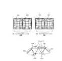
図3は単眼カメラの組合せによるパノラマカメラユニット配置構成を示す図である。パノラマカメラユニット12Aは、同一平面に2台の単眼カメラを画角が僅かに重なるように広画角に配置した構成としている(ユニット12AR,12AL)。単眼カメラの組合せによるパノラマカメラユニット12Aで格子パターン58A,58Bを撮像した場合、左右のパノラマ撮像範囲をそれぞれ60,62に示す。パノラマ撮像による画像は画像の周辺部で著しく丸みを帯びた歪みが生じる。同図のパノラマ撮像は格子パターンの歪みを補正し、画像を凹状に示したものである。 FIG. 3 is a diagram showing a panoramic camera unit arrangement configuration by a combination of monocular cameras. The
図4は単眼カメラの組合せによるパノラマカメラユニット対の配置構成を示す図である。パノラマカメラユニット12A1,12A2を2台設置した場合、単眼カメラの12A1Lと12A2Rを光軸方向が並行となるように配置している。これにより、12A1Lと12A2Rとを組み合わせてステレオ撮像することができる。また、パノラマカメラユニット12A1,12A2でそれぞれ撮像した画像を64,66に示す。図示のように、画像64,66はいずれも格子パターンが略同じように歪んでいる。このようにいずれの画像も、近似したモデルで歪みを表せるので、歪み補正のパラメータが近似した形になり、ステレオ測距時のキャリブレーションデータに基づきステレオの左右画像の歪曲収差の補正を含み、視差を算出する際のエピポーララインが左右画像で同一画像で同一線上に一致するように画像を幾何変換するレクティフィケーション処理を簡素化することができる。 FIG. 4 is a diagram showing an arrangement configuration of a panoramic camera unit pair by a combination of monocular cameras. When two panoramic camera units 12A1 and 12A2 are installed, the monocular cameras 12A1L and 12A2R are arranged so that the optical axis directions are parallel. Thereby, stereo imaging can be performed by combining 12A1L and 12A2R. Reference numerals 64 and 66 denote images captured by the panoramic camera units 12A1 and 12A2, respectively. As shown in the figure, the images 64 and 66 are distorted in substantially the same lattice pattern. Thus, since any image can represent distortion with an approximate model, the distortion correction parameters are approximated, including correction of distortion aberration of the left and right stereo images based on calibration data during stereo distance measurement, Rectification processing for geometrically transforming images so that epipolar lines when calculating parallax are the same in the same image in the left and right images can be simplified.
図5はステレオアダプタを用いたパノラマカメラユニット配置構成を示す図である。パノラマカメラユニット12Bを前述の図3と同様に、左右の撮像範囲が僅かに重なるように配置している。また、図3同様に格子パターン58A,58Bを撮像した場合、左右のパノラマ撮像範囲をそれぞれ68,70に示す。この場合、ステレオアダプタを用いると撮像素子一つで、前述の撮像素子2つ分のパノラマカメラユニット12Aと同じ撮像領域を撮像することになる。このため図示のようにパノラマカメラユニット12Aと比べ、画像の周辺部で格子パターンの歪みが左右で異なっている。 FIG. 5 is a diagram showing a panoramic camera unit arrangement configuration using a stereo adapter. The
図6はステレオアダプタを用いたパノラマカメラユニット対の配置構成を示す図である。パノラマカメラユニット12B1,12B2は、同一側面上に2つ並べて配置してある。これにより、ユニット対12B1R−12B2R、及び12B1L−12B2Lの組合せによる撮像レンズの光軸方向が並行となり、ステレオ撮像することができる。 FIG. 6 is a diagram showing an arrangement configuration of a panoramic camera unit pair using a stereo adapter. Two panoramic camera units 12B1 and 12B2 are arranged side by side on the same side surface. Thereby, the optical axis direction of the imaging lens by the combination of unit pair 12B1R-12B2R and 12B1L-12B2L becomes parallel, and stereo imaging can be performed.
また、パノラマカメラユニット12B1,12B2でそれぞれ撮像した画像を68,70に示す。図示のように、ステレオアダプタのミラーの角度を変えて光軸間の輻輳角が開くような構造にしたパノラマカメラユニット12Bの画像は、左右(58A,58Bあるいは58C,58D)で歪みの出方が著しく異なっている。これは、ステレオアダプタを用いた場合には折り曲げミラーを介して前レンズ群のディストーション(歪み)と後レンズ群のディストーションの複合ディストーションとなり、かつ共軸ではないためである。このため左右で歪み方が異なる。 68 and 70 show images captured by the panoramic camera units 12B1 and 12B2, respectively. As shown in the figure, the image of the
したがって、歪み方が共通となるユニット対12B1R−12B2R、あるいは12B1L−12B2Lの分割視野画像を用いたほうが、歪みがいずれも近似しているため、歪み補正後の解像度差も少ないので、ステレオの対応点探索が容易になる。 Therefore, using the divided field images of the unit pairs 12B1R-12B2R or 12B1L-12B2L, which share the same distortion, since the distortions are close to each other, the resolution difference after distortion correction is smaller, so stereo support Point search becomes easy.
なお、撮像手段となるパノラマカメラユニット12は、撮像素子を2台配置するユニット12A、あるいはステレオアダプタ50を用いたユニット12Bのいずれか一方を対に組み合わせた構成とし、このユニット12の対(12A1−12A2,12B1−12B2)は任意に選択することができる。 The panoramic camera unit 12 serving as an image pickup means is configured by combining either a
図7は実施形態に係るパノラマカメラユニット12Aの車両の搭載構成を示す図である。図示のように、撮像手段配置物体としての車両40の前後部には、撮像手段としてのパノラマカメラユニット12Aが複数装備されている。図示の例では、車両40の前部にパノラマカメラユニット12A1,12A2が装備されている。各カメラは車両前方のパノラマ撮像範囲a−b,c−dを撮像するようにしている。また、車両の後部にも、撮像手段としてのパノラマカメラユニット12A1,12A2が装備されている。同様に各カメラは車両後方におけるパノラマ撮像範囲a−b,c−dを撮像するようにしている。 FIG. 7 is a diagram illustrating a vehicle mounting configuration of the
この実施形態では、車両の前後に配置したパノラマカメラユニット12A1,12A2からの画像データを取り込むための画像選択装置30(30a、30b)が設けられ、運転席近傍に設けられた視点変換画像生成/表示装置10からの画像選択コマンドを受け、必要画像を選択して画像情報として視点変換画像生成/表示装置10に返すように構成されている。なお、データ送受信は車内LAN回線を通じて行うようにしても良い。 In this embodiment, an image selection device 30 (30a, 30b) for capturing image data from panoramic camera units 12A1, 12A2 arranged in front of and behind the vehicle is provided, and a viewpoint-converted image generator / It is configured to receive an image selection command from the
図8は実施形態に係るパノラマカメラとステレオカメラの撮像範囲を示す図である。同図(1)は、車両40の後方パノラマカメラユニット12A1によるパノラマカメラ撮像範囲を示す。同図(2)は同じく後方パノラマカメラユニット12A2のパノラマ撮像範囲を示す。同図(3)は、後方パノラマカメラユニット12A1bと、12A2cの組合せによるステレオ撮像範囲を示す。図示のように、後方パノラマカメラユニット12A1bと、12A2cの組合せは撮像レンズの光軸方向が並行となるように配置しているためステレオ撮像が可能となる。したがって、ステレオ撮像による後述の距離画像データを生成することができる。 FIG. 8 is a diagram illustrating an imaging range of the panoramic camera and the stereo camera according to the embodiment. FIG. 1A shows a panoramic camera imaging range by the rear panoramic camera unit 12A1 of the
なお、画像選択装置30の読み出し方を変えることで、パノラマ撮像による広画角撮像と、ステレオ撮像による空間モデル生成のためのステレオ測距を任意に実施することができる。 Note that by changing the reading method of the
各パノラマカメラユニット12により撮影された画像データは画像選択装置30にパケット送信するようになっている。各パノラマカメラユニット12から取得すべき画像データは、設定される仮想視点によって決定するので、設定された仮想視点に対応する画像データを取得すべく画像選択装置30を設けている。この画像選択装置30によって任意のパノラマカメラユニット12に付帯したバッファ装置から入力してくる画像データパケットから、設定された仮想視点に対応する画像データパケットが選択され、後段の画像合成処理に利用される。 The image data photographed by each panorama camera unit 12 is packet-transmitted to the
また、撮像手段は画像選択装置30によって、複数のパノラマカメラユニット12の切替えを行う。制御手段となる画像選択装置30はパノラマカメラユニット12による広画角撮像と、パノラマカメラユニット対の組合せで構成されるステレオ撮像とに切替える。画像選択装置30は後述の視点選択装置36の仮想視点に基づいて広画角撮像あるいはステレオ撮像を切替え制御している。さらに、パノラマカメラユニット12Bでは、撮像レンズの光軸方向が並行となる位置に配置された2つのカメラの左右いずれかの片側視野から撮像させるように切替えを行うことができる。撮像手段の実写画像データは実写画像データ記憶装置32に一時保管される。 Further, the imaging means switches the plurality of panoramic camera units 12 by the
ところで、測距手段となる測距装置13は、本実施形態ではステレオ撮像による測距と、レーザレーダやミリ波レーダなどのレーダによる測距とを併用しても良い。 By the way, in the present embodiment, the
ステレオ撮像による測距は複数の異なる視点から同一の被写体を撮影し、これらの画像中における被写体の同一点の対応を求め、三角測量の原理によって被写体までの距離を算出している。より具体的にはステレオ撮像手段によって撮像された画像の右画像全体を小領域に分割してステレオ測距計算を行う範囲を決定して、ついで左画像の同一画像とされる画像の位置を検出して、それらの画像の視差を算出して、左右カメラの取り付け位置の関係から対象物までの距離を演算するようにすればよい。このステレオカメラにより撮像された2またはそれ以上の画像間のステレオ測距で得られた距離情報により、距離画像が生成される。 In the distance measurement by stereo imaging, the same subject is photographed from a plurality of different viewpoints, the correspondence of the same point of the subject in these images is obtained, and the distance to the subject is calculated by the principle of triangulation. More specifically, the entire right image of the image captured by the stereo imaging means is divided into small areas to determine a range for performing stereo distance measurement, and then the position of the image that is the same as the left image is detected. Then, the parallax of those images may be calculated, and the distance to the object may be calculated from the relationship between the attachment positions of the left and right cameras. A distance image is generated based on distance information obtained by stereo distance measurement between two or more images captured by the stereo camera.
また、キャリブレーション装置18は3次元の実世界に配置された撮像手段についての、その3次元実世界における、撮像手段の取付位置、取付角度、レンズ歪み補正値、レンズの焦点距離等のカメラ特性を表すカメラパラメータを決定し、特定する。キャリブレーションによって得られたカメラパラメータはキャリブレーションデータとしてキャリブレーションデータ記憶装置17に一時に格納される。 Further, the
空間モデル生成装置15ではパノラマカメラユニット12による広画角撮像およびステレオ撮像の画像情報と、測距装置13による距離画像データ28に基づいて空間モデルを生成することができる。 The spatial
合成画像生成手段となる空間再構成装置14は、撮像手段から得られた画像を構成する各々の画素と、3次元座標系の点との対応関係を計算し、空間データを生成し、空間データ記憶装置24に一時保管する。前記計算は各々の撮像手段から得られた画像のすべての画素に対して実施する。 The
視点変換手段となる視点変換装置19は、3次元空間の画像を任意の視点位置から見込んだ画像に変換可能とし、任意に設定した視点を指定できる。すなわち、前記三次元座標系の、どの位置から、どの角度で、どれだけの倍率で、画像を見たいかを指定する。また、前記視点からの画像を、前記空間データから再現し、表示手段となる表示装置20に表示する。 The
なお、視点変換画像生成/表示装置10には、自車モデルを記憶格納している撮像装置配置物体モデル記憶装置34が設けられ、空間再構成する場合に自車モデルを同時に表示できるようにしている。また、視点選択装置36が設けられており、予め規定されている設定仮想視点に対応する画像データを仮想視点データ記憶装置38に格納しておき、視点選択処理が行われたときに即時に対応画像を用いて視点変換装置19に送信し、選択された仮想視点に対応する変換画像を表示させるようにしている。 Note that the viewpoint conversion image generation /
上記構成による本発明に係る画像生成装置を用いた画像の生成方法を、図9を用いて説明する。図9は本発明に係る画像生成方法の処理手順を示すフローチャートである。
(S102)表示する任意の仮想視点を視点選択装置36で選択する。
(S104)複数のパノラマカメラユニット12による、広画角あるいはステレオの撮像を選択する。
(S106)選択したパノラマカメラユニット12による撮像を行なう。
(S108)あらかじめキャリブレーション装置18によってステレオマッチングに用いるキャリブレーションを実施し、選択したパノラマカメラユニット12に応じた基線長、内部、外部のカメラパラメータ等のキャリブレーションデータを生成して選択する。
(S110)得られたキャリブレーションデータをもとに選択した撮像画像のステレオマッチングを行う。すなわち、ステレオ視した左右の画像から所定のウィンドを切り出し、エピポーラ線上をスキャンしながら、ウィンド画像の正規化相関値などを算出することにより、対応点を検索し、左右画像の画素間の視差を算出する。上記視差から、キャリブレーションデータを基に距離を算出し、得られた距離データを距離画像データとする。
(S112)空間モデル更新手段となる空間再構成装置14には、パノラマカメラユニット12による広画角撮像およびステレオ撮像の画像情報と、距離画像データが入力される。これらを所望の距離で選択的に用いることにより、より詳細な空間モデルが生成される。
(S114)この空間モデルに対応する実写画像データをキャリブレーションデータに従って撮像手段からの入力画像を3次元空間の空間モデルにマッピングする。テクスチャマッピングがなされた空間データが生成される。
(S116)空間再構成装置14によって作成された空間データを参照して、所望の仮想視点から見た視点変換画像を視点変換装置19で生成する。
(S118)生成した視点変換画像データを表示装置20で表示する。An image generation method using the image generation apparatus according to the present invention having the above configuration will be described with reference to FIG. FIG. 9 is a flowchart showing the processing procedure of the image generation method according to the present invention.
(S102) The
(S104) Wide-angle or stereo imaging by a plurality of panoramic camera units 12 is selected.
(S106) Imaging by the selected panoramic camera unit 12 is performed.
(S108) Calibration for stereo matching is performed by the
(S110) Stereo matching of the picked-up image selected based on the obtained calibration data is performed. In other words, a predetermined window is cut out from the left and right images viewed in stereo, and the corresponding correlation is searched by calculating the normalized correlation value of the window image while scanning the epipolar line, and the parallax between the pixels of the left and right images is calculated. calculate. From the parallax, the distance is calculated based on the calibration data, and the obtained distance data is used as the distance image data.
(S112) The
(S114) The actual image data corresponding to the space model is mapped to the space model in the three-dimensional space according to the calibration data. Spatial data subjected to texture mapping is generated.
(S116) With reference to the spatial data created by the
(S118) The generated viewpoint conversion image data is displayed on the
ところで、本実施形態に係るステレオ撮像のステレオマッチングによる距離画像の生成を示すフローチャートを図10に示す。ここでは、ステレオアダプタ50のパノラマカメラユニット12B1,12B2を用いた場合について説明する。以下、左パノラマカメラユニットと、右パノラマカメラユニットから入力された画像のうち、ステレオペアを形成する右側(12B1R−12B2R)の視野画像を用いる例を示す。 Incidentally, a flowchart showing generation of a distance image by stereo matching of stereo imaging according to the present embodiment is shown in FIG. Here, a case where the panoramic camera units 12B1 and 12B2 of the stereo adapter 50 are used will be described. Hereinafter, an example of using the right (12B1R-12B2R) visual field image forming a stereo pair among the images input from the left panorama camera unit and the right panorama camera unit will be described.
それぞれのステレオカメラユニット12B1,12B2の撮像画像の右側視野部分を右側視野切り出し処理により、所定の大きさに切り出し(S200),(S204)、ステレオ左画像と、ステレオ右画像を生成する。
(S202)得られたステレオ左画像。
(S206)得られたステレオ右画像。
(S208)得られたレクティフィケーション・キャリブレーションデータ。あらかじめキャリブレーション装置18によってレクティフィケーションに用いるキャリブレーションを実施し、選択したステレオカメラユニットの右側カメラあるいは左側カメラに応じた基線長、内部、外部のカメラパラメータ等のキャリブレーションデータを生成する。
(S210)次に、左右それぞれのステレオ画像をレクティフィケーション用のキャリブレーションデータに基づいて、ステレオの左右画像の歪曲収差の補正を行い、エピポーラ線上に左右画像の対応点が同一線上に来るように画像を幾何変換するレクティフィケーション処理を行なう。
(S212)得られたレクティフィケーション後のステレオ左画像。
(S214)得られたレクティフィケーション後のステレオ右画像。
(S216)このレクティフィケーション後の左右画像をステレオマッチング処理し、対応点検索を行い、視差を算出する。これにより、画像上の各点の視差量のマップが生成され、これが視差データとなる。
(S218)得られた視差データ。
(S220)得られたステレオ距離キャリブレーションデータ。あらかじめキャリブレーション装置18によってステレオ測距に用いるキャリブレーションを実施し、選択したステレオカメラユニットに応じた基線長、内部、外部のカメラパラメータ等のキャリブレーションデータを生成する。
(S222)ステレオ距離キャリブレーションにより、視差量は基準点からの距離に変換され、距離画像データが生成される。
(S224)得られた距離画像データ。The right visual field portion of the captured image of each stereo camera unit 12B1, 12B2 is cut into a predetermined size by right visual field cutout processing (S200), (S204), and a stereo left image and a stereo right image are generated.
(S202) The obtained stereo left image.
(S206) The obtained stereo right image.
(S208) The obtained rectification calibration data. The
(S210) Next, the left and right stereo images are corrected for distortion aberration of the stereo left and right images based on the calibration data for rectification so that the corresponding points of the left and right images are on the same line on the epipolar line. A rectification process for geometrically transforming the image is performed.
(S212) The obtained stereo left image after rectification.
(S214) The obtained stereo right image after rectification.
(S216) The left and right images after this rectification are subjected to stereo matching processing, corresponding point search is performed, and parallax is calculated. Thereby, a map of the amount of parallax at each point on the image is generated, and this becomes parallax data.
(S218) The obtained parallax data.
(S220) The obtained stereo distance calibration data. Calibration for use in stereo distance measurement is performed in advance by the
(S222) By the stereo distance calibration, the parallax amount is converted into a distance from the reference point, and distance image data is generated.
(S224) The obtained distance image data.
以上のような処理を行うことにより、複数のステレオカメラの画像から距離画像データを算出することができる。得られた距離画像データは空間モデルの生成に用いている。 By performing the processing as described above, distance image data can be calculated from images of a plurality of stereo cameras. The obtained distance image data is used for generating a spatial model.
このような画像生成装置10によれば、車両に配置された1又は複数の撮像手段による画像情報に基づいて視点変換画像を生成する装置であって、前記撮像手段を視点の異なる2つのカメラを組み合わせたパノラマカメラユニットにより構成し、前記パノラマカメラユニットによる広画角撮像と、前記パノラマカメラユニットを対に並べて形成し、撮像レンズの光軸方向が並行となる位置に配置された前記カメラの組合せによるステレオ撮像と、が可能となるように構成しているため、撮像画面上の対象物の距離測定を行うことができ、この距離画像データを用いて画像生成の精度を上げることができる。 According to such an
また、前記パノラマカメラユニットによる広画角撮像により取得した画像に適用する広画角撮像処理と、撮像レンズの光軸方向が並行となる位置に配置された前記カメラの組合せによるステレオ撮像により取得した画像に適用するステレオ撮像処理との切替手段を設けたことにより、広画角による画像データと距離画像データを用いることができ画像生成の精度を向上させることができる。 Moreover, it acquired by the stereo imaging | photography by the combination of the said camera arrange | positioned in the position where the optical axis direction of an imaging lens and the wide-angle imaging processing applied to the image acquired by the said panoramic camera unit by the wide-angle imaging | photography is parallel. By providing switching means for stereo imaging processing applied to an image, image data with a wide angle of view and distance image data can be used, and the accuracy of image generation can be improved.
前記ステレオ画像処理は、対に組み合わせた前記パノラマカメラユニットにおける撮像レンズの光軸方向が並行となる位置に配置された2つのカメラの左右いずれかの片側視野から撮像させるように切替可能にしているため、ステレオ画像処理は2つのカメラの左右いずれかの対となる片側視野から撮像することができ、歪み補正処理が共通となり、処理が簡略化でき、空間モデルを容易に生成することができる。 The stereo image processing can be switched so that an image is taken from one of the left and right visual fields of two cameras arranged at positions where the optical axis directions of the imaging lenses in the panoramic camera unit combined in a pair are parallel. Therefore, the stereo image processing can be taken from one side view that is a pair of left and right of the two cameras, the distortion correction processing is common, the processing can be simplified, and a spatial model can be easily generated.
生成した仮想視点画像を車両のモニタに表示すれば車両周辺状況を広範囲で確認することが可能となり、安全性を大幅に向上させることができる。
また、撮像手段は建築物に配置することにより、前述同様に建築物の内部又は外部周辺状況の画像生成における画像精度を向上させることができる。If the generated virtual viewpoint image is displayed on the monitor of the vehicle, it is possible to check the situation around the vehicle in a wide range, and the safety can be greatly improved.
Further, by arranging the imaging means in the building, the image accuracy in generating an image of the internal or external surrounding situation of the building can be improved as described above.
上述した各例において、複数の撮像装置は、それらによって、いわゆる3眼ステレオカメラを構成するように用いても、あるいは4眼ステレオカメラを構成するように用いてもよい。このように3眼あるいは4眼ステレオカメラを用いると、3次元再構成処理などにおいて、より信頼度が高く、安定した処理結果が得られることが知られている(富田文明:情報処理学会発行「情報処理」第42巻第4号の「高機能3次元視覚システム」等)。特に複数カメラを2方向の基線長方向にカメラを複数台配置するといわゆるマルチベースライン方式のステレオカメラを実現することが可能となり、より高精度のステレオ測距が可能となる。 In each of the above-described examples, the plurality of imaging devices may be used so as to configure a so-called trinocular stereo camera or may be used so as to configure a four-eye stereo camera. In this way, it is known that using a three-lens or four-eye stereo camera provides more reliable and stable processing results in three-dimensional reconstruction processing (Fumiaki Tomita: published by the Information Processing Society of Japan) Information processing "Volume 42 No.4" High-function 3D visual system "). In particular, when a plurality of cameras are arranged in two base length directions, a so-called multi-baseline stereo camera can be realized, and more accurate stereo distance measurement can be realized.
なお、カメラなど撮像手段を所定の形態で設置する対象物は、車両に装着した例を示しているが、撮像装置配置物体として例えば、歩行者、街路、店舗や住居、オフィスなどの建築物などに取り付けた場合でも同様の画像生成の実施が可能である。このように構成することで、監視カメラや人に取り付けた、映像ベースの情報取得を実施するウェアラブルコンピュータなどへの適応が可能となる。 In addition, although the object which installs imaging means, such as a camera in a predetermined form, shows an example mounted on a vehicle, examples of imaging device placement objects include buildings such as pedestrians, streets, stores, houses, offices, etc. The same image generation can be performed even when attached to the. With this configuration, it is possible to adapt to a monitoring camera or a wearable computer that is attached to a person and performs video-based information acquisition.
10………視点変換画像生成/表示装置、12………パノラマカメラユニット、13………測距装置、14………空間再構成装置、15………空間モデル生成装置、18………キャリブレーション装置、19………視点変換装置、20………表示装置、22………空間モデル記憶装置、24………空間データ記憶装置、26………視点変換画像データ記憶装置、28………距離画像データ記憶装置、30………画像選択装置、32………実写画像データ記憶装置、34………撮像装置配置物体モデル記憶装置、36………視点選択装置、38………仮想視点データ記憶装置、40………車両、50………ステレオアダプタ。DESCRIPTION OF
Claims (7)
Translated fromJapaneseThe image generating apparatus according to claim 4, wherein the imaging unit is disposed in a building.
Priority Applications (3)
| Application Number | Priority Date | Filing Date | Title |
|---|---|---|---|
| JP2004211371AJP2006033570A (en) | 2004-07-20 | 2004-07-20 | Image generating device |
| US11/177,983US20060018509A1 (en) | 2004-07-20 | 2005-07-08 | Image generation device |
| CNB2005100850581ACN100452869C (en) | 2004-07-20 | 2005-07-20 | Image generation device |
Applications Claiming Priority (1)
| Application Number | Priority Date | Filing Date | Title |
|---|---|---|---|
| JP2004211371AJP2006033570A (en) | 2004-07-20 | 2004-07-20 | Image generating device |
Publications (1)
| Publication Number | Publication Date |
|---|---|
| JP2006033570Atrue JP2006033570A (en) | 2006-02-02 |
Family
ID=35657168
Family Applications (1)
| Application Number | Title | Priority Date | Filing Date |
|---|---|---|---|
| JP2004211371APendingJP2006033570A (en) | 2004-07-20 | 2004-07-20 | Image generating device |
Country Status (3)
| Country | Link |
|---|---|
| US (1) | US20060018509A1 (en) |
| JP (1) | JP2006033570A (en) |
| CN (1) | CN100452869C (en) |
Cited By (7)
| Publication number | Priority date | Publication date | Assignee | Title |
|---|---|---|---|---|
| JP2008247239A (en)* | 2007-03-30 | 2008-10-16 | Aisin Seiki Co Ltd | Blind spot image display device for vehicles |
| JP2009077092A (en)* | 2007-09-20 | 2009-04-09 | Hitachi Ltd | Multi camera system |
| JP2010524279A (en)* | 2007-03-09 | 2010-07-15 | イーストマン コダック カンパニー | Distance map generation type multi-lens camera |
| KR20160043138A (en)* | 2012-03-09 | 2016-04-20 | 가부시키가이샤 리코 | Image capturing apparatus, image capture system, image processing method, information processing apparatus, and computer-readable storage medium |
| JP2016175586A (en)* | 2015-03-20 | 2016-10-06 | 株式会社デンソーアイティーラボラトリ | Vehicle periphery monitoring device, vehicle periphery monitoring method, and program |
| JP2018533248A (en)* | 2015-08-24 | 2018-11-08 | フラウンホーファー−ゲゼルシャフト・ツール・フェルデルング・デル・アンゲヴァンテン・フォルシュング・アインゲトラーゲネル・フェライン | 3D multi-aperture imaging device |
| US11244434B2 (en) | 2015-08-24 | 2022-02-08 | Fraunhofer-Gesellschaft zur Förderung der angewandten Forschung e.V. | Multi-aperture imaging device |
Families Citing this family (89)
| Publication number | Priority date | Publication date | Assignee | Title |
|---|---|---|---|---|
| US8170284B2 (en)* | 2005-01-11 | 2012-05-01 | Pioneer Corporation | Apparatus and method for displaying image of view in front of vehicle |
| US8154599B2 (en)* | 2005-07-29 | 2012-04-10 | Panasonic Corporation | Imaging region adjustment device |
| JP4812510B2 (en)* | 2006-05-17 | 2011-11-09 | アルパイン株式会社 | Vehicle peripheral image generation apparatus and photometric adjustment method for imaging apparatus |
| US8269820B2 (en)* | 2006-11-02 | 2012-09-18 | Konica Minolta Holdings, Inc. | Wide-angle image acquiring method and wide-angle stereo camera device |
| DE102006052779A1 (en)* | 2006-11-09 | 2008-05-15 | Bayerische Motoren Werke Ag | Method for generating an overall image of the surroundings of a motor vehicle |
| US8009178B2 (en)* | 2007-06-29 | 2011-08-30 | Microsoft Corporation | Augmenting images for panoramic display |
| US11792538B2 (en) | 2008-05-20 | 2023-10-17 | Adeia Imaging Llc | Capturing and processing of images including occlusions focused on an image sensor by a lens stack array |
| DK3876510T3 (en) | 2008-05-20 | 2024-11-11 | Adeia Imaging Llc | CAPTURE AND PROCESSING OF IMAGES USING MONOLITHIC CAMERA ARRAY WITH HETEROGENEOUS IMAGES |
| US8866920B2 (en) | 2008-05-20 | 2014-10-21 | Pelican Imaging Corporation | Capturing and processing of images using monolithic camera array with heterogeneous imagers |
| CN101321302B (en)* | 2008-07-08 | 2010-06-09 | 浙江大学 | 3D real-time acquisition system based on camera array |
| JP5247590B2 (en)* | 2009-05-21 | 2013-07-24 | キヤノン株式会社 | Information processing apparatus and calibration processing method |
| JP5337658B2 (en)* | 2009-10-02 | 2013-11-06 | 株式会社トプコン | Wide-angle imaging device and measurement system |
| JP2011091527A (en)* | 2009-10-21 | 2011-05-06 | Panasonic Corp | Video conversion device and imaging apparatus |
| EP2502115A4 (en) | 2009-11-20 | 2013-11-06 | Pelican Imaging Corp | CAPTURE AND IMAGE PROCESSING USING A MONOLITHIC CAMERAS NETWORK EQUIPPED WITH HETEROGENEOUS IMAGERS |
| JP2011209269A (en)* | 2010-03-08 | 2011-10-20 | Ricoh Co Ltd | Image pickup apparatus and range obtaining system |
| JP5479956B2 (en) | 2010-03-10 | 2014-04-23 | クラリオン株式会社 | Ambient monitoring device for vehicles |
| US8928793B2 (en) | 2010-05-12 | 2015-01-06 | Pelican Imaging Corporation | Imager array interfaces |
| US9264695B2 (en) | 2010-05-14 | 2016-02-16 | Hewlett-Packard Development Company, L.P. | System and method for multi-viewpoint video capture |
| JP5450330B2 (en)* | 2010-09-16 | 2014-03-26 | 株式会社ジャパンディスプレイ | Image processing apparatus and method, and stereoscopic image display apparatus |
| JP5481337B2 (en)* | 2010-09-24 | 2014-04-23 | 株式会社東芝 | Image processing device |
| US8878950B2 (en) | 2010-12-14 | 2014-11-04 | Pelican Imaging Corporation | Systems and methods for synthesizing high resolution images using super-resolution processes |
| DE102011010865A1 (en) | 2011-02-10 | 2012-03-08 | Daimler Ag | Vehicle with a device for detecting a vehicle environment |
| EP2708019B1 (en) | 2011-05-11 | 2019-10-16 | FotoNation Limited | Systems and methods for transmitting and receiving array camera image data |
| DE102011080702B3 (en)* | 2011-08-09 | 2012-12-13 | 3Vi Gmbh | Object detection device for a vehicle, vehicle having such an object detection device |
| US20130070060A1 (en) | 2011-09-19 | 2013-03-21 | Pelican Imaging Corporation | Systems and methods for determining depth from multiple views of a scene that include aliasing using hypothesized fusion |
| CN104081414B (en) | 2011-09-28 | 2017-08-01 | Fotonation开曼有限公司 | Systems and methods for encoding and decoding light field image files |
| EP2817955B1 (en) | 2012-02-21 | 2018-04-11 | FotoNation Cayman Limited | Systems and methods for the manipulation of captured light field image data |
| US9210392B2 (en) | 2012-05-01 | 2015-12-08 | Pelican Imaging Coporation | Camera modules patterned with pi filter groups |
| JP2015534734A (en) | 2012-06-28 | 2015-12-03 | ペリカン イメージング コーポレイション | System and method for detecting defective camera arrays, optical arrays, and sensors |
| US20140002674A1 (en) | 2012-06-30 | 2014-01-02 | Pelican Imaging Corporation | Systems and Methods for Manufacturing Camera Modules Using Active Alignment of Lens Stack Arrays and Sensors |
| PL4296963T3 (en) | 2012-08-21 | 2025-04-28 | Adeia Imaging Llc | Method for depth detection in images captured using array cameras |
| WO2014032020A2 (en) | 2012-08-23 | 2014-02-27 | Pelican Imaging Corporation | Feature based high resolution motion estimation from low resolution images captured using an array source |
| US8948497B2 (en)* | 2012-09-04 | 2015-02-03 | Digital Signal Corporation | System and method for increasing resolution of images obtained from a three-dimensional measurement system |
| EP4307659A1 (en) | 2012-09-28 | 2024-01-17 | Adeia Imaging LLC | Generating images from light fields utilizing virtual viewpoints |
| WO2014078443A1 (en) | 2012-11-13 | 2014-05-22 | Pelican Imaging Corporation | Systems and methods for array camera focal plane control |
| US9091628B2 (en) | 2012-12-21 | 2015-07-28 | L-3 Communications Security And Detection Systems, Inc. | 3D mapping with two orthogonal imaging views |
| US9462164B2 (en) | 2013-02-21 | 2016-10-04 | Pelican Imaging Corporation | Systems and methods for generating compressed light field representation data using captured light fields, array geometry, and parallax information |
| US9374512B2 (en) | 2013-02-24 | 2016-06-21 | Pelican Imaging Corporation | Thin form factor computational array cameras and modular array cameras |
| CN103149696A (en)* | 2013-02-28 | 2013-06-12 | 京东方科技集团股份有限公司 | Display system |
| US9774789B2 (en) | 2013-03-08 | 2017-09-26 | Fotonation Cayman Limited | Systems and methods for high dynamic range imaging using array cameras |
| US8866912B2 (en) | 2013-03-10 | 2014-10-21 | Pelican Imaging Corporation | System and methods for calibration of an array camera using a single captured image |
| US9888194B2 (en) | 2013-03-13 | 2018-02-06 | Fotonation Cayman Limited | Array camera architecture implementing quantum film image sensors |
| US9106784B2 (en) | 2013-03-13 | 2015-08-11 | Pelican Imaging Corporation | Systems and methods for controlling aliasing in images captured by an array camera for use in super-resolution processing |
| US9124831B2 (en) | 2013-03-13 | 2015-09-01 | Pelican Imaging Corporation | System and methods for calibration of an array camera |
| WO2014165244A1 (en) | 2013-03-13 | 2014-10-09 | Pelican Imaging Corporation | Systems and methods for synthesizing images from image data captured by an array camera using restricted depth of field depth maps in which depth estimation precision varies |
| US9578259B2 (en) | 2013-03-14 | 2017-02-21 | Fotonation Cayman Limited | Systems and methods for reducing motion blur in images or video in ultra low light with array cameras |
| WO2014153098A1 (en) | 2013-03-14 | 2014-09-25 | Pelican Imaging Corporation | Photmetric normalization in array cameras |
| US9497429B2 (en) | 2013-03-15 | 2016-11-15 | Pelican Imaging Corporation | Extended color processing on pelican array cameras |
| US9438888B2 (en) | 2013-03-15 | 2016-09-06 | Pelican Imaging Corporation | Systems and methods for stereo imaging with camera arrays |
| US9445003B1 (en) | 2013-03-15 | 2016-09-13 | Pelican Imaging Corporation | Systems and methods for synthesizing high resolution images using image deconvolution based on motion and depth information |
| US10122993B2 (en) | 2013-03-15 | 2018-11-06 | Fotonation Limited | Autofocus system for a conventional camera that uses depth information from an array camera |
| US9898856B2 (en) | 2013-09-27 | 2018-02-20 | Fotonation Cayman Limited | Systems and methods for depth-assisted perspective distortion correction |
| WO2015061769A1 (en)* | 2013-10-26 | 2015-04-30 | The Lightco Inc. | Methods and apparatus for use with multiple optical chains |
| US9467627B2 (en) | 2013-10-26 | 2016-10-11 | The Lightco Inc. | Methods and apparatus for use with multiple optical chains |
| US9264592B2 (en) | 2013-11-07 | 2016-02-16 | Pelican Imaging Corporation | Array camera modules incorporating independently aligned lens stacks |
| US10119808B2 (en) | 2013-11-18 | 2018-11-06 | Fotonation Limited | Systems and methods for estimating depth from projected texture using camera arrays |
| WO2015081279A1 (en) | 2013-11-26 | 2015-06-04 | Pelican Imaging Corporation | Array camera configurations incorporating multiple constituent array cameras |
| US10089740B2 (en) | 2014-03-07 | 2018-10-02 | Fotonation Limited | System and methods for depth regularization and semiautomatic interactive matting using RGB-D images |
| CN104079917A (en)* | 2014-07-14 | 2014-10-01 | 中国地质大学(武汉) | A 360-degree panoramic stereo camera |
| JP2017531976A (en) | 2014-09-29 | 2017-10-26 | フォトネイション ケイマン リミテッド | System and method for dynamically calibrating an array camera |
| US10412274B2 (en)* | 2015-03-18 | 2019-09-10 | Ricoh Company, Ltd. | Imaging unit, vehicle control unit and heat transfer method for imaging unit |
| US9942474B2 (en) | 2015-04-17 | 2018-04-10 | Fotonation Cayman Limited | Systems and methods for performing high speed video capture and depth estimation using array cameras |
| KR102483838B1 (en) | 2015-04-19 | 2023-01-02 | 포토내이션 리미티드 | Multi-Baseline Camera Array System Architecture for Depth Augmentation in VR/AR Applications |
| JP6416408B2 (en)* | 2015-09-28 | 2018-11-07 | 富士フイルム株式会社 | Ranging device, ranging method, and ranging program |
| JP6672075B2 (en)* | 2016-05-25 | 2020-03-25 | キヤノン株式会社 | CONTROL DEVICE, CONTROL METHOD, AND PROGRAM |
| CN108616719B (en)* | 2016-12-29 | 2021-04-27 | 杭州海康威视数字技术股份有限公司 | Method, device and system for monitoring video display |
| US10482618B2 (en) | 2017-08-21 | 2019-11-19 | Fotonation Limited | Systems and methods for hybrid depth regularization |
| JP7069692B2 (en)* | 2017-12-20 | 2022-05-18 | トヨタ自動車株式会社 | Image display device |
| FR3080937B1 (en)* | 2018-05-03 | 2021-06-04 | Commissariat Energie Atomique | REAL-TIME DISTANCE RECOGNITION METHOD AND DEVICE |
| CN109903344B (en)* | 2019-02-28 | 2021-04-20 | 东软睿驰汽车技术(沈阳)有限公司 | Calibration method and device |
| CN111753584B (en)* | 2019-03-28 | 2023-09-26 | 杭州海康威视数字技术股份有限公司 | Intelligent analysis method and system |
| US12092800B2 (en) | 2019-06-24 | 2024-09-17 | Circle Optics, Inc. | Opto-mechanics of panoramic capture devices with abutting cameras |
| US11270110B2 (en) | 2019-09-17 | 2022-03-08 | Boston Polarimetrics, Inc. | Systems and methods for surface modeling using polarization cues |
| WO2021071992A1 (en) | 2019-10-07 | 2021-04-15 | Boston Polarimetrics, Inc. | Systems and methods for augmentation of sensor systems and imaging systems with polarization |
| DE112020005932T5 (en) | 2019-11-30 | 2023-01-05 | Boston Polarimetrics, Inc. | SYSTEMS AND METHODS FOR SEGMENTATION OF TRANSPARENT OBJECTS USING POLARIZATION CHARACTERISTICS |
| EP4081933A4 (en) | 2020-01-29 | 2024-03-20 | Intrinsic Innovation LLC | Systems and methods for characterizing object pose detection and measurement systems |
| US11797863B2 (en) | 2020-01-30 | 2023-10-24 | Intrinsic Innovation Llc | Systems and methods for synthesizing data for training statistical models on different imaging modalities including polarized images |
| US11953700B2 (en) | 2020-05-27 | 2024-04-09 | Intrinsic Innovation Llc | Multi-aperture polarization optical systems using beam splitters |
| US12020455B2 (en) | 2021-03-10 | 2024-06-25 | Intrinsic Innovation Llc | Systems and methods for high dynamic range image reconstruction |
| US12069227B2 (en) | 2021-03-10 | 2024-08-20 | Intrinsic Innovation Llc | Multi-modal and multi-spectral stereo camera arrays |
| US11954886B2 (en) | 2021-04-15 | 2024-04-09 | Intrinsic Innovation Llc | Systems and methods for six-degree of freedom pose estimation of deformable objects |
| US11290658B1 (en) | 2021-04-15 | 2022-03-29 | Boston Polarimetrics, Inc. | Systems and methods for camera exposure control |
| US12067746B2 (en) | 2021-05-07 | 2024-08-20 | Intrinsic Innovation Llc | Systems and methods for using computer vision to pick up small objects |
| US12175741B2 (en) | 2021-06-22 | 2024-12-24 | Intrinsic Innovation Llc | Systems and methods for a vision guided end effector |
| US12340538B2 (en) | 2021-06-25 | 2025-06-24 | Intrinsic Innovation Llc | Systems and methods for generating and using visual datasets for training computer vision models |
| US12172310B2 (en) | 2021-06-29 | 2024-12-24 | Intrinsic Innovation Llc | Systems and methods for picking objects using 3-D geometry and segmentation |
| US11689813B2 (en) | 2021-07-01 | 2023-06-27 | Intrinsic Innovation Llc | Systems and methods for high dynamic range imaging using crossed polarizers |
| US12293535B2 (en) | 2021-08-03 | 2025-05-06 | Intrinsic Innovation Llc | Systems and methods for training pose estimators in computer vision |
| DE102022103940A1 (en)* | 2022-02-18 | 2023-08-24 | Dspace Gmbh | Test setup and method for testing a stereo camera |
Citations (3)
| Publication number | Priority date | Publication date | Assignee | Title |
|---|---|---|---|---|
| JP2000092521A (en)* | 1998-08-28 | 2000-03-31 | Lucent Technol Inc | Stereoscopic panoramic image display system |
| JP2002027494A (en)* | 2000-07-07 | 2002-01-25 | Matsushita Electric Works Ltd | System for imaging and presenting stereoscopic image |
| JP2003312415A (en)* | 2002-04-23 | 2003-11-06 | Nissan Motor Co Ltd | Pre-presentation device for vehicles |
Family Cites Families (7)
| Publication number | Priority date | Publication date | Assignee | Title |
|---|---|---|---|---|
| GB2185360B (en)* | 1986-01-11 | 1989-10-25 | Pilkington Perkin Elmer Ltd | Display system |
| JPH0767022A (en)* | 1993-08-26 | 1995-03-10 | Canon Inc | Compound eye imaging device |
| US6111702A (en)* | 1995-11-30 | 2000-08-29 | Lucent Technologies Inc. | Panoramic viewing system with offset virtual optical centers |
| US6055012A (en)* | 1995-12-29 | 2000-04-25 | Lucent Technologies Inc. | Digital multi-view video compression with complexity and compatibility constraints |
| JP2000259997A (en)* | 1999-03-05 | 2000-09-22 | Nissan Motor Co Ltd | Height and inter-vehicle distance measuring device for preceding vehicle |
| WO2001028250A1 (en)* | 1999-10-12 | 2001-04-19 | Matsushita Electric Industrial Co., Ltd. | Monitor camera, method of adjusting camera, and vehicle monitor system |
| US20050146607A1 (en)* | 2004-01-06 | 2005-07-07 | Romeo Linn | Object Approaching Detection Anti Blind e-Mirrors System |
- 2004
- 2004-07-20JPJP2004211371Apatent/JP2006033570A/enactivePending
- 2005
- 2005-07-08USUS11/177,983patent/US20060018509A1/ennot_activeAbandoned
- 2005-07-20CNCNB2005100850581Apatent/CN100452869C/ennot_activeExpired - Fee Related
Patent Citations (3)
| Publication number | Priority date | Publication date | Assignee | Title |
|---|---|---|---|---|
| JP2000092521A (en)* | 1998-08-28 | 2000-03-31 | Lucent Technol Inc | Stereoscopic panoramic image display system |
| JP2002027494A (en)* | 2000-07-07 | 2002-01-25 | Matsushita Electric Works Ltd | System for imaging and presenting stereoscopic image |
| JP2003312415A (en)* | 2002-04-23 | 2003-11-06 | Nissan Motor Co Ltd | Pre-presentation device for vehicles |
Cited By (11)
| Publication number | Priority date | Publication date | Assignee | Title |
|---|---|---|---|---|
| JP2010524279A (en)* | 2007-03-09 | 2010-07-15 | イーストマン コダック カンパニー | Distance map generation type multi-lens camera |
| JP2008247239A (en)* | 2007-03-30 | 2008-10-16 | Aisin Seiki Co Ltd | Blind spot image display device for vehicles |
| JP2009077092A (en)* | 2007-09-20 | 2009-04-09 | Hitachi Ltd | Multi camera system |
| KR20160043138A (en)* | 2012-03-09 | 2016-04-20 | 가부시키가이샤 리코 | Image capturing apparatus, image capture system, image processing method, information processing apparatus, and computer-readable storage medium |
| KR101692194B1 (en) | 2012-03-09 | 2017-01-02 | 가부시키가이샤 리코 | Image capturing apparatus, image capture system, image processing method, information processing apparatus, and computer-readable storage medium |
| US9607358B2 (en) | 2012-03-09 | 2017-03-28 | Ricoh Company, Limited | Image capturing apparatus, image capture system, image processing method, information processing apparatus, and computer-readable storage medium |
| US11049215B2 (en) | 2012-03-09 | 2021-06-29 | Ricoh Company, Ltd. | Image capturing apparatus, image capture system, image processing method, information processing apparatus, and computer-readable storage medium |
| JP2016175586A (en)* | 2015-03-20 | 2016-10-06 | 株式会社デンソーアイティーラボラトリ | Vehicle periphery monitoring device, vehicle periphery monitoring method, and program |
| JP2018533248A (en)* | 2015-08-24 | 2018-11-08 | フラウンホーファー−ゲゼルシャフト・ツール・フェルデルング・デル・アンゲヴァンテン・フォルシュング・アインゲトラーゲネル・フェライン | 3D multi-aperture imaging device |
| US10701340B2 (en) | 2015-08-24 | 2020-06-30 | Fraunhofer-Gesellschaft zur Förderung der angewandten Forschung e.V. | 3D multi-aperture imaging device |
| US11244434B2 (en) | 2015-08-24 | 2022-02-08 | Fraunhofer-Gesellschaft zur Förderung der angewandten Forschung e.V. | Multi-aperture imaging device |
Also Published As
| Publication number | Publication date |
|---|---|
| CN100452869C (en) | 2009-01-14 |
| CN1725857A (en) | 2006-01-25 |
| US20060018509A1 (en) | 2006-01-26 |
Similar Documents
| Publication | Publication Date | Title |
|---|---|---|
| JP2006033570A (en) | Image generating device | |
| US20240000295A1 (en) | Light field capture and rendering for head-mounted displays | |
| JP4257356B2 (en) | Image generating apparatus and image generating method | |
| US20060029256A1 (en) | Method of generating image and device | |
| KR101666959B1 (en) | Image processing apparatus having a function for automatically correcting image acquired from the camera and method therefor | |
| JP3593466B2 (en) | Method and apparatus for generating virtual viewpoint image | |
| CN115023736B (en) | Method for measuring the topography of an environment | |
| CN108765496A (en) | A kind of multiple views automobile looks around DAS (Driver Assistant System) and method | |
| KR101077584B1 (en) | Apparatus and method for processing images obtained by a plurality of cameras | |
| JP4414661B2 (en) | Stereo adapter and range image input device using the same | |
| JP2016531281A (en) | System and method for modeling and calibration of imaging apparatus | |
| JP2008085446A (en) | Image generating apparatus and image generating method | |
| JP2014520337A (en) | 3D image synthesizing apparatus and method for visualizing vehicle periphery | |
| JP2006060425A (en) | Image generating method and apparatus thereof | |
| WO1999058927A1 (en) | Image generating device and method | |
| JP2006119843A (en) | Image forming method, and apparatus thereof | |
| JP4545503B2 (en) | Image generating apparatus and method | |
| US20230379445A1 (en) | Image processing device, moving apparatus, image processing method, and storage medium | |
| JP7442072B2 (en) | Three-dimensional displacement measurement method and three-dimensional displacement measurement device | |
| JP4581512B2 (en) | Three-dimensional image processing apparatus, optical axis adjustment method, and optical axis adjustment support method | |
| US20250078208A1 (en) | Image processing system, movable apparatus, image processing method, and storage medium | |
| JP2006031101A (en) | Image generation method and device therefor | |
| JPH09305796A (en) | Image information processing device | |
| KR101857977B1 (en) | Image apparatus for combining plenoptic camera and depth camera, and image processing method | |
| JP2006054503A (en) | Image generation method and apparatus |
Legal Events
| Date | Code | Title | Description |
|---|---|---|---|
| A621 | Written request for application examination | Free format text:JAPANESE INTERMEDIATE CODE: A621 Effective date:20070706 | |
| A977 | Report on retrieval | Free format text:JAPANESE INTERMEDIATE CODE: A971007 Effective date:20091214 | |
| A131 | Notification of reasons for refusal | Free format text:JAPANESE INTERMEDIATE CODE: A131 Effective date:20091217 | |
| A02 | Decision of refusal | Free format text:JAPANESE INTERMEDIATE CODE: A02 Effective date:20100407 |