JP2006033203A - Mobile terminal - Google Patents
Mobile terminalDownload PDFInfo
- Publication number
- JP2006033203A JP2006033203AJP2004206563AJP2004206563AJP2006033203AJP 2006033203 AJP2006033203 AJP 2006033203AJP 2004206563 AJP2004206563 AJP 2004206563AJP 2004206563 AJP2004206563 AJP 2004206563AJP 2006033203 AJP2006033203 AJP 2006033203A
- Authority
- JP
- Japan
- Prior art keywords
- key
- unit
- sheet
- board
- terminal device
- Prior art date
- Legal status (The legal status is an assumption and is not a legal conclusion. Google has not performed a legal analysis and makes no representation as to the accuracy of the status listed.)
- Pending
Links
Images


Landscapes
- Switch Cases, Indication, And Locking (AREA)
- Push-Button Switches (AREA)
- Telephone Set Structure (AREA)
Abstract
Translated fromJapaneseDescription
Translated fromJapanese本発明は、携帯端末装置に関するものである。 The present invention relates to a portable terminal device.
キー入力部の防水性能を向上させた携帯端末装置としては、特許文献1記載のものが知られている。この従来例において、キートップユニットは、スペーサシートを挟んだ上下電極とドームシートとを有するキー基板上に防滴シートを積層して形成される。防滴シートの表面周縁にはリブが形成され、該リブとケース裏面とによりキートップユニットを挟み付けることにより防水のためのシーリングがなされる。
しかし、上述した従来例におけるシーリングは、防滴シートのリブをパッキンとして機能させることにより達成されるものであるが、ケース、あるいはリブの製造誤差の集積によってリブの撓み代にはばらつきが発生することは避けられない。 However, the sealing in the conventional example described above is achieved by causing the ribs of the drip-proof sheet to function as packings, but variations in the bending allowance of the ribs occur due to accumulation of case or rib manufacturing errors. It is inevitable.
この結果、リブの撓み代が過小になって所望のシール性能が発揮されないことがあり、信頼性に欠けるという欠点がある。
本発明は、以上の欠点を解消すべくなされたものであって、防水性能の信頼性を高めた携帯端末装置の提供を目的とする。As a result, there is a drawback in that the bending allowance of the rib becomes too small and the desired sealing performance may not be exhibited, resulting in lack of reliability.
The present invention has been made to solve the above drawbacks, and an object of the present invention is to provide a portable terminal device with improved waterproof performance.
携帯情報端末装置のキー操作面は、フロントケース9に形成されたキーユニット収容凹部10内にキーユニット8を保持して形成される。キーユニット8は、キー基板6と、このキー基板6上に積層されるキートップユニット7とを有して構成され、キー基板6の電極等への浸水を防止するために、キー基板6とキートップユニット7との間に防水シート11が介装される。 The key operation surface of the portable information terminal device is formed by holding the
防水シート11は、キートップユニット7への操作力が効率よくキー基板6に伝達されるように、薄い膜状に形成され、裏面四周がキーユニット収容凹部10の底壁部に接合される。薄膜に形成される防水シート11を裏面においてフロントケース9に接着することにより、シーリング面を確実に確保することができ、シーリングの信頼性が向上する。 The
防水シート11のフロントケース9への接合には、防水シート11の裏面に予め貼り付けておいた粘着テープを利用することができる。 For joining the
本発明によれば、防水性能の信頼性を高めることができる。 According to the present invention, the reliability of waterproof performance can be increased.
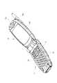
図1に携帯電話として構成された本発明の実施の形態を示す。携帯電話は、固定側本体17に対して可動側本体18を折り畳み可能に連結して形成される。可動側本体18には、アンテナ18aが装着され、図1に示す使用姿勢において、正面に現れる位置に液晶表示部18bおよびスピーカ18cが配置される。 FIG. 1 shows an embodiment of the present invention configured as a mobile phone. The mobile phone is formed by connecting the
一方、使用姿勢において、表面に複数のキートップ19、19・・が並んだキー操作面が現れる固定側本体17は、図4に示すように、リアケース20とフロントケース9とを重ね合わせて形成されるケース本体内に制御基板21を収容して形成される。リアケース20とフロントケース9との連結界面には、ケース本体内への水等の侵入を防止するために適宜のパッキン(図示せず)が介装される。リアケース20の底壁には、制御基板21を固定するための取付ボス20aが立設される。 On the other hand, in the use posture, the fixed-side
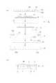
上記キー操作面は、フロントケース9の表面にキーユニット8を配置して形成される。図3に示すように、キーユニット8は、キー基板6と、このキー基板6上に配置されるキートップユニット7とからなり、これらキー基板6とキートップユニット7との間に防水シート11が介装される。図3(b)に示すように、キー基板6は、フレキシブルプリント基板2上に形成される下部電極1と、上部電極シート4上の上部電極4aとをスペーサシート3により形成される間隙を隔てて対峙させ、さらに上部電極シート4上に操作時の節度感等を付与する目的でドームシート5を被せて形成される。また、フレキシブルプリント基板2上には、後述するキートップ19を照らす光源として使用されるLED(小型点灯デバイス12)が実装され、さらに、一端部には配線部(ケーブル14)が形成される。 The key operation surface is formed by arranging the
一方、キートップユニット7は、複数のキートップ19、19・・を同一のシート上に形成したもので、キートップ19には所定の数字等が表示される。このキートップユニット7は、キートップ19をキーカバー16の開口16aから外部に露出させた状態で配置され、所定のキートップ19を押圧操作すると、上下電極4a、1が接触してキー押圧が検知される。 On the other hand, the key
上記防水シート11は、透水しない柔軟な合成樹脂製のシートで、この実施の形態においては、板厚0.08(mm)程度のPET樹脂が使用される。また、この防水シート11は、フレキシブルプリント基板2上のLED12からの照射光をキートップに有効に伝達するために、透明に形成される。 The
以上のように構成されるキーユニット8を収容するフロントケース9には、防水シート11から上方の構成要素を嵌合、収容するキーユニット収容凹部10と、キーユニット収容凹部10の中央部をさらに窪ませて形成され、上記キーユニット8および防水シート11より小さなキー基板6を収容するキー基板収容凹部13とが形成される。キー基板収容凹部13は、上記キー基板6の高さにほぼ等しい深さ寸法を有し、所定箇所にキー基板6の配線部14を挿通させるための挿通孔15が開設される。 The
これらの組立に際し、まず、キー基板6をキー基板収容凹部13に嵌合させ、固定する。キー基板6の固定は、配線部14を挿通孔15に挿通させて制御基板21上のコネクタ21aに接続した後、フレキシブルプリント基板2の背面をキー基板収容凹部13の底壁に接着して行われる。接着剤を使用したキー基板6の接着により、挿通孔15およびキー基板6とフロントケース9との接触界面は完全にシーリングされるために、以後、キー基板6近傍からのケース内への水の侵入は完全に防止される。 In assembling these parts, first, the
次いで、上記キー基板6の上に防水シート11が固定される。防水シート11の固定は、接着剤によることも可能であるが、接着剤の流れ出しによるキー基板6の可動部への影響を避け、さらに、防水シート11の接着剤による接着可能性等を考慮して、粘着剤によるのが望ましい。粘着剤による固定は、防水シート11、あるいはフロントケース9側に予め粘着シートを貼り付けて行われる。 Next, the
防水シート11の固定は、上記キー基板収容凹部13を囲むようにして配置されるキーユニット収容凹部10の底壁に対して行われ、四周裏面が固定された防水シート11は、固定時のみ、あるいはそれ自体の柔軟性等によってキートップへの操作性に悪影響を与えることがない。 The
以上のようにして防水シート11を固定すると、キー基板6に対する防水シーリングが確保され、上下電極4a、1間の短絡等が防止される。また、防水シート11は、広げられた状態で四周裏面が粘着されるために、薄膜状であるにもかかわらず、シーリングの信頼性も高い。 When the
キートップユニット7は、上記防水シート11上に載置され、キーカバー16により固定される。上述したようにキーカバー16には、キートップが挿通する開口16aが各キートップ19に対応して複数設けられる。また、図2に示すように、キーカバー16は側縁から垂下する垂下壁16dを備えており、この垂下壁16dの下端でキートップユニット7の周縁を押さえ付け、キートップユニット7のめくれ上がりを規制する。 The key
さらに、上記垂下壁16dには、係止脚16bが形成される。係止脚16bには係止部16cが突設され、キーカバー16は、この係止部16cをキーユニット収容凹部10の側壁に形成された被係止部10aに係止して着脱可能に装着される。キーカバー16を係止状態で装着し、フロントケース9に対して着脱可能とすることにより、砂等が紛れ込んだ際には、ユーザがキーカバー16を取り外して砂等を取り除くことが可能になり、しかも、内部の気密は防水シート11およびキー基板6により保障されるために、機能障害の原因となることもない。 Further, a
1 下部電極
2 プリント基板
3 スペーサシート
4 上部電極シート
5 ドームシート
6 キー基板
7 キートップユニット
8 キーユニット
9 フロントケース
10 キーユニット収容凹部
11 防水シート
12 小型点灯デバイス
13 キー基板収容凹部
14 ケーブル
15 挿通孔
16 キーカバーDESCRIPTION OF
Claims (5)
Translated fromJapaneseフロントケース表面に形成されたキーユニット収容凹部内にキーユニットを固定した携帯情報端末装置であって、
前記キー基板とキートップユニットの間には、四周裏面がキーユニット収容凹部の底壁に接着されて該接着界面を防水シーリング面とする薄膜状の防水シートが介装される携帯情報端末装置。A key unit having a key board in which a spacer sheet, an upper electrode sheet, and a dome sheet are laminated on a printed board on which a lower electrode is formed, and a key top unit laminated on the key board;
A portable information terminal device in which a key unit is fixed in a key unit housing recess formed on the front case surface,
A portable information terminal device is provided between the key substrate and the key top unit, with a thin-film waterproof sheet having a four-sided back surface bonded to the bottom wall of the key unit housing recess and having the adhesive interface as a waterproof sealing surface.
防水シートは透光性を有する材料により形成される請求項1記載の携帯情報端末装置。On the printed circuit board, a small lighting device is mounted,
The portable information terminal device according to claim 1, wherein the waterproof sheet is formed of a translucent material.
かつ、キー基板収容凹部には、キー基板からケース内部空間内に導入されるケーブルの挿通孔が開設される請求項3記載の携帯情報端末装置。The key board is fixed to the bottom wall surface of the key board housing recess by an adhesive layer whose back four sides also serve as waterproof sealing,
4. The portable information terminal device according to claim 3, wherein an insertion hole for a cable introduced from the key board into the case internal space is opened in the key board housing recess.
5. The portable information terminal device according to claim 1, wherein the key top unit is pressed by a key cover that can be attached to and detached from the key unit housing recess to prevent the key top unit from falling off the front case.
Priority Applications (1)
| Application Number | Priority Date | Filing Date | Title |
|---|---|---|---|
| JP2004206563AJP2006033203A (en) | 2004-07-13 | 2004-07-13 | Mobile terminal |
Applications Claiming Priority (1)
| Application Number | Priority Date | Filing Date | Title |
|---|---|---|---|
| JP2004206563AJP2006033203A (en) | 2004-07-13 | 2004-07-13 | Mobile terminal |
Publications (2)
| Publication Number | Publication Date |
|---|---|
| JP2006033203Atrue JP2006033203A (en) | 2006-02-02 |
| JP2006033203A5 JP2006033203A5 (en) | 2007-05-24 |
Family
ID=35899058
Family Applications (1)
| Application Number | Title | Priority Date | Filing Date |
|---|---|---|---|
| JP2004206563APendingJP2006033203A (en) | 2004-07-13 | 2004-07-13 | Mobile terminal |
Country Status (1)
| Country | Link |
|---|---|
| JP (1) | JP2006033203A (en) |
Cited By (12)
| Publication number | Priority date | Publication date | Assignee | Title |
|---|---|---|---|---|
| JP2007068160A (en)* | 2005-08-26 | 2007-03-15 | Lg Electronics Inc | Keypad assembly and mobile communication terminal including the same |
| JP2008052606A (en)* | 2006-08-25 | 2008-03-06 | Kyocera Corp | Electronics |
| JP2008288151A (en)* | 2007-05-21 | 2008-11-27 | Casio Hitachi Mobile Communications Co Ltd | Waterproofing terminal structure |
| WO2011032313A1 (en)* | 2009-09-17 | 2011-03-24 | 海能达通信股份有限公司 | Communication device |
| JP2012059487A (en)* | 2010-09-08 | 2012-03-22 | Fujitsu Toshiba Mobile Communications Ltd | Key panel unit and electronic apparatus equipped with the key panel unit |
| US8248810B2 (en) | 2006-08-25 | 2012-08-21 | Kyocera Corporation | Electronic device |
| KR101263123B1 (en) | 2010-11-09 | 2013-05-15 | 후지쯔 가부시끼가이샤 | Electronic device |
| US8569640B2 (en)* | 2008-07-14 | 2013-10-29 | Oki Electric Industry Co., Ltd. | Key switch structure |
| WO2015192473A1 (en)* | 2014-06-17 | 2015-12-23 | 中兴通讯股份有限公司 | Waterproof apparatus for terminal side-key, and terminal |
| JP2016193009A (en)* | 2015-03-31 | 2016-11-17 | 京楽産業.株式会社 | Game machine |
| JP2018148459A (en)* | 2017-03-07 | 2018-09-20 | 京セラ株式会社 | Electronics |
| JP2023514892A (en)* | 2021-01-27 | 2023-04-12 | サムスン エレクトロニクス カンパニー リミテッド | Electronic device including sealing member |
- 2004
- 2004-07-13JPJP2004206563Apatent/JP2006033203A/enactivePending
Cited By (17)
| Publication number | Priority date | Publication date | Assignee | Title |
|---|---|---|---|---|
| US7773958B2 (en) | 2005-08-26 | 2010-08-10 | Lg Electronics Inc. | Key pad assembly and mobile communication terminal having the same |
| JP2007068160A (en)* | 2005-08-26 | 2007-03-15 | Lg Electronics Inc | Keypad assembly and mobile communication terminal including the same |
| US8248810B2 (en) | 2006-08-25 | 2012-08-21 | Kyocera Corporation | Electronic device |
| JP2008052606A (en)* | 2006-08-25 | 2008-03-06 | Kyocera Corp | Electronics |
| JP2008288151A (en)* | 2007-05-21 | 2008-11-27 | Casio Hitachi Mobile Communications Co Ltd | Waterproofing terminal structure |
| US8569640B2 (en)* | 2008-07-14 | 2013-10-29 | Oki Electric Industry Co., Ltd. | Key switch structure |
| WO2011032313A1 (en)* | 2009-09-17 | 2011-03-24 | 海能达通信股份有限公司 | Communication device |
| US8750950B2 (en) | 2009-09-17 | 2014-06-10 | Hytera Communications Corp., Ltd. | Communication device |
| JP2012059487A (en)* | 2010-09-08 | 2012-03-22 | Fujitsu Toshiba Mobile Communications Ltd | Key panel unit and electronic apparatus equipped with the key panel unit |
| KR101263123B1 (en) | 2010-11-09 | 2013-05-15 | 후지쯔 가부시끼가이샤 | Electronic device |
| WO2015192473A1 (en)* | 2014-06-17 | 2015-12-23 | 中兴通讯股份有限公司 | Waterproof apparatus for terminal side-key, and terminal |
| US9875862B2 (en) | 2014-06-17 | 2018-01-23 | Zte Corporation | Waterproof sealing arrangement for a side key on a terminal |
| JP2016193009A (en)* | 2015-03-31 | 2016-11-17 | 京楽産業.株式会社 | Game machine |
| JP2018148459A (en)* | 2017-03-07 | 2018-09-20 | 京セラ株式会社 | Electronics |
| JP2023514892A (en)* | 2021-01-27 | 2023-04-12 | サムスン エレクトロニクス カンパニー リミテッド | Electronic device including sealing member |
| JP7365490B2 (en) | 2021-01-27 | 2023-10-19 | サムスン エレクトロニクス カンパニー リミテッド | Electronic devices including sealing members |
| US12072742B2 (en) | 2021-01-27 | 2024-08-27 | Samsung Electronics Co., Ltd. | Electronic device including sealing member |
Similar Documents
| Publication | Publication Date | Title |
|---|---|---|
| US9839151B2 (en) | Electronic device having a waterproof structure | |
| US8008591B2 (en) | Key button structure for electronic device | |
| JP4538483B2 (en) | Waterproof structure and electronic equipment | |
| US10129994B1 (en) | Water-tight electronic device display | |
| CN106128827B (en) | Side key structure and mobile terminal | |
| JP2006344528A (en) | Waterproof structure of push-button switch | |
| JPH0373973B2 (en) | ||
| JP2006033203A (en) | Mobile terminal | |
| US20050202787A1 (en) | Keypad assembly | |
| JP2001102763A (en) | Portable input device | |
| JP5354639B2 (en) | Waterproof housing structure and electronic device | |
| CN215833928U (en) | Waterproof fingerprint module and terminal | |
| WO2019184778A1 (en) | Press key device and terminal apparatus | |
| JP4886465B2 (en) | Electronics | |
| JP2012199867A (en) | Portable wireless device | |
| CN102548281B (en) | Mobile device | |
| CN215955140U (en) | Key structure and electronic equipment | |
| JP2009215739A (en) | Portable machine of electronic key system | |
| CN215118180U (en) | display device | |
| JP4609801B2 (en) | Key device and mobile phone | |
| JP2008009904A (en) | Electronic device | |
| JP2004193496A (en) | Drip-proof structure of electronic equipment | |
| CN217426599U (en) | Soft touch type key unit and electronic equipment | |
| JP3108352U (en) | Waterproof key unit and electronic device including the same | |
| JP2013168890A (en) | Portable terminal |
Legal Events
| Date | Code | Title | Description |
|---|---|---|---|
| A521 | Written amendment | Free format text:JAPANESE INTERMEDIATE CODE: A523 Effective date:20070329 | |
| A621 | Written request for application examination | Free format text:JAPANESE INTERMEDIATE CODE: A621 Effective date:20070705 | |
| A977 | Report on retrieval | Free format text:JAPANESE INTERMEDIATE CODE: A971007 Effective date:20090217 | |
| A131 | Notification of reasons for refusal | Free format text:JAPANESE INTERMEDIATE CODE: A131 Effective date:20090414 | |
| A02 | Decision of refusal | Free format text:JAPANESE INTERMEDIATE CODE: A02 Effective date:20091110 |