JP2006030483A - Rinsing method and development processing method - Google Patents
Rinsing method and development processing methodDownload PDFInfo
- Publication number
- JP2006030483A JP2006030483AJP2004207574AJP2004207574AJP2006030483AJP 2006030483 AJP2006030483 AJP 2006030483AJP 2004207574 AJP2004207574 AJP 2004207574AJP 2004207574 AJP2004207574 AJP 2004207574AJP 2006030483 AJP2006030483 AJP 2006030483A
- Authority
- JP
- Japan
- Prior art keywords
- substrate
- surfactant
- development
- pure water
- polyethylene glycol
- Prior art date
- Legal status (The legal status is an assumption and is not a legal conclusion. Google has not performed a legal analysis and makes no representation as to the accuracy of the status listed.)
- Pending
Links
- 238000000034methodMethods0.000titleclaimsabstractdescription81
- 238000003672processing methodMethods0.000titleclaimsabstractdescription39
- 239000000758substrateSubstances0.000claimsabstractdescription143
- 239000004094surface-active agentSubstances0.000claimsabstractdescription138
- 239000007788liquidSubstances0.000claimsabstractdescription129
- 239000002202Polyethylene glycolSubstances0.000claimsabstractdescription47
- 229920001223polyethylene glycolPolymers0.000claimsabstractdescription47
- -1acetylene glycolChemical compound0.000claimsabstractdescription40
- 125000001165hydrophobic groupChemical group0.000claimsabstractdescription30
- HSFWRNGVRCDJHI-UHFFFAOYSA-Nalpha-acetyleneNatural productsC#CHSFWRNGVRCDJHI-UHFFFAOYSA-N0.000claimsabstractdescription28
- LYCAIKOWRPUZTN-UHFFFAOYSA-Nethylene glycolNatural productsOCCOLYCAIKOWRPUZTN-UHFFFAOYSA-N0.000claimsabstractdescription28
- WGCNASOHLSPBMP-UHFFFAOYSA-NhydroxyacetaldehydeNatural productsOCC=OWGCNASOHLSPBMP-UHFFFAOYSA-N0.000claimsabstractdescription28
- 239000000693micelleSubstances0.000claimsabstractdescription26
- OKTJSMMVPCPJKN-UHFFFAOYSA-NCarbonChemical compound[C]OKTJSMMVPCPJKN-UHFFFAOYSA-N0.000claimsabstractdescription5
- 229910052799carbonInorganic materials0.000claimsabstractdescription5
- XLYOFNOQVPJJNP-UHFFFAOYSA-NwaterSubstancesOXLYOFNOQVPJJNP-UHFFFAOYSA-N0.000claimsdescription95
- 238000001035dryingMethods0.000claimsdescription23
- 235000014113dietary fatty acidsNutrition0.000claimsdescription11
- 229930195729fatty acidNatural products0.000claimsdescription11
- 239000000194fatty acidSubstances0.000claimsdescription11
- 125000000217alkyl groupChemical group0.000claimsdescription9
- USIUVYZYUHIAEV-UHFFFAOYSA-Ndiphenyl etherChemical compoundC=1C=CC=CC=1OC1=CC=CC=C1USIUVYZYUHIAEV-UHFFFAOYSA-N0.000claimsdescription8
- 238000007599dischargingMethods0.000claimsdescription8
- 125000004432carbon atomChemical groupC*0.000claimsdescription5
- 150000005215alkyl ethersChemical class0.000claimsdescription3
- 230000007547defectEffects0.000abstractdescription22
- 238000004090dissolutionMethods0.000abstractdescription6
- 238000002425crystallisationMethods0.000abstract1
- 230000008025crystallizationEffects0.000abstract1
- 239000000243solutionSubstances0.000description54
- 238000001556precipitationMethods0.000description21
- 239000007864aqueous solutionSubstances0.000description18
- 230000007246mechanismEffects0.000description16
- 239000013256coordination polymerSubstances0.000description12
- 238000004140cleaningMethods0.000description9
- 238000002156mixingMethods0.000description9
- 239000000126substanceSubstances0.000description9
- 239000002245particleSubstances0.000description8
- 239000004065semiconductorSubstances0.000description6
- 230000000694effectsEffects0.000description4
- 239000002699waste materialSubstances0.000description4
- 230000015572biosynthetic processEffects0.000description3
- 230000003028elevating effectEffects0.000description3
- 238000004519manufacturing processMethods0.000description3
- RTZKZFJDLAIYFH-UHFFFAOYSA-NDiethyl etherChemical compoundCCOCCRTZKZFJDLAIYFH-UHFFFAOYSA-N0.000description2
- 206010047571Visual impairmentDiseases0.000description2
- 238000006243chemical reactionMethods0.000description2
- 239000000470constituentSubstances0.000description2
- 230000007423decreaseEffects0.000description2
- 238000010586diagramMethods0.000description2
- 238000000206photolithographyMethods0.000description2
- 239000012190activatorSubstances0.000description1
- 239000003795chemical substances by applicationSubstances0.000description1
- 238000001816coolingMethods0.000description1
- 238000007865dilutingMethods0.000description1
- 238000009826distributionMethods0.000description1
- 238000004945emulsificationMethods0.000description1
- 238000005516engineering processMethods0.000description1
- 230000002708enhancing effectEffects0.000description1
- 239000004973liquid crystal related substanceSubstances0.000description1
- 238000006116polymerization reactionMethods0.000description1
- 239000012487rinsing solutionSubstances0.000description1
- 230000009466transformationEffects0.000description1
- 238000011144upstream manufacturingMethods0.000description1
Images


Classifications
- G—PHYSICS
- G03—PHOTOGRAPHY; CINEMATOGRAPHY; ANALOGOUS TECHNIQUES USING WAVES OTHER THAN OPTICAL WAVES; ELECTROGRAPHY; HOLOGRAPHY
- G03F—PHOTOMECHANICAL PRODUCTION OF TEXTURED OR PATTERNED SURFACES, e.g. FOR PRINTING, FOR PROCESSING OF SEMICONDUCTOR DEVICES; MATERIALS THEREFOR; ORIGINALS THEREFOR; APPARATUS SPECIALLY ADAPTED THEREFOR
- G03F7/00—Photomechanical, e.g. photolithographic, production of textured or patterned surfaces, e.g. printing surfaces; Materials therefor, e.g. comprising photoresists; Apparatus specially adapted therefor
- G03F7/26—Processing photosensitive materials; Apparatus therefor
- G03F7/40—Treatment after imagewise removal, e.g. baking
- H—ELECTRICITY
- H01—ELECTRIC ELEMENTS
- H01L—SEMICONDUCTOR DEVICES NOT COVERED BY CLASS H10
- H01L21/00—Processes or apparatus adapted for the manufacture or treatment of semiconductor or solid state devices or of parts thereof
- H01L21/67—Apparatus specially adapted for handling semiconductor or electric solid state devices during manufacture or treatment thereof; Apparatus specially adapted for handling wafers during manufacture or treatment of semiconductor or electric solid state devices or components ; Apparatus not specifically provided for elsewhere
- H01L21/67005—Apparatus not specifically provided for elsewhere
- H01L21/67011—Apparatus for manufacture or treatment
- H01L21/67017—Apparatus for fluid treatment
- H01L21/67028—Apparatus for fluid treatment for cleaning followed by drying, rinsing, stripping, blasting or the like
- H01L21/6704—Apparatus for fluid treatment for cleaning followed by drying, rinsing, stripping, blasting or the like for wet cleaning or washing
- H01L21/67051—Apparatus for fluid treatment for cleaning followed by drying, rinsing, stripping, blasting or the like for wet cleaning or washing using mainly spraying means, e.g. nozzles
Landscapes
- Physics & Mathematics (AREA)
- General Physics & Mathematics (AREA)
- Engineering & Computer Science (AREA)
- Condensed Matter Physics & Semiconductors (AREA)
- Manufacturing & Machinery (AREA)
- Computer Hardware Design (AREA)
- Microelectronics & Electronic Packaging (AREA)
- Power Engineering (AREA)
- Photosensitive Polymer And Photoresist Processing (AREA)
- Exposure Of Semiconductors, Excluding Electron Or Ion Beam Exposure (AREA)
Abstract
Description
Translated fromJapanese本発明は、露光パターンを現像処理した後の半導体ウエハ等の基板をリンス処理するリンス処理方法およびそのようなリンス処理を含む現像処理方法に関する。 The present invention relates to a rinsing method for rinsing a substrate such as a semiconductor wafer after developing an exposure pattern, and a developing method including such a rinsing process.
例えば、半導体デバイスの製造プロセスにおいては、半導体ウエハ(以下「ウエハ」という)の表面にレジスト液を塗布してレジスト膜を形成し、このレジスト膜を所定パターンで露光処理し、こうしてレジスト膜に形成された露光パターンを現像するという、いわゆるフォトリソグラフィー技術が用いられており、現像処理によって露光パターンに対応したレジストパターンが形成される。 For example, in a semiconductor device manufacturing process, a resist solution is applied to the surface of a semiconductor wafer (hereinafter referred to as “wafer”) to form a resist film, and this resist film is exposed in a predetermined pattern, thus forming a resist film. A so-called photolithography technique for developing the exposed exposure pattern is used, and a resist pattern corresponding to the exposure pattern is formed by development processing.
このようなフォトリソグラフィー技術の各工程の中の現像処理においては、ウエハに現像液を供給して現像液パドルを形成し、所定時間自然対流により現像処理を進行させた後、現像液を振り切り、次いで、洗浄液として純水を供給してウエハ上に残存する現像液を洗い流し、その後、ウエハを高速で回転してウエハ上に残存する現像液および洗浄液を振り切りウエハを乾燥させている。 In the development process in each step of such a photolithography technique, a developer is supplied to the wafer to form a developer paddle, and after a predetermined time of natural convection, the developer is shaken off. Next, pure water is supplied as a cleaning solution to wash away the developer remaining on the wafer, and then the wafer is rotated at a high speed to shake off the developer and cleaning solution remaining on the wafer to dry the wafer.
ところで、近時、露光技術等の進歩により半導体デバイスの微細化が一層進行しており、微細かつ高アスペクト比のレジストパターンが出現するに至り、上述のような現像工程における最終の振り切り乾燥において、リンス液がパターン間から抜け出る際に、リンス液の表面張力によりレジストパターンが引っ張られて倒れるという、いわゆる「パターン倒れ」が発生することが問題となっている。 By the way, in recent years, semiconductor devices have been further miniaturized due to advances in exposure technology and the like, leading to the appearance of fine and high aspect ratio resist patterns, in the final shake-off drying in the development process as described above, When the rinsing liquid comes out between the patterns, there is a problem that a so-called “pattern collapse” occurs in which the resist pattern is pulled and falls due to the surface tension of the rinsing liquid.
このような問題を解決する技術として、特許文献1には、例えばリンス液中に界面活性剤溶液を混入してリンス液の表面張力を低下させる技術が提案されている。また、特許文献2には、現像処理後に基板のリンス処理を行う際に界面活性剤を供給するプロセスが開示されている。 As a technique for solving such a problem, Patent Document 1 proposes a technique for reducing the surface tension of a rinsing liquid by mixing a surfactant solution in the rinsing liquid, for example. Patent Document 2 discloses a process for supplying a surfactant when the substrate is rinsed after the development process.
しかしながら、リンス液にこのような界面活性剤を用いる場合には、従来の純水とは異なり、界面活性剤がパーティクルになってウエハを汚染する、つまり、析出系欠陥が生じて品質を低下させるという問題が生じている。また、界面活性剤がレジストパターンを溶解したり、CD(Critical Dimension)に変動を与えるという問題も発生している。界面活性剤を用いたリンス処理において、これらの問題を考慮した最適なプロセスは未だ見出されていない。
本発明はかかる事情に鑑みてなされたものであって、現像処理における析出系欠陥の発生を抑制するリンス処理方法および現像処理方法を提供することを目的とする。また、本発明はCD変動を抑制するリンス処理方法および現像処理方法を提供することを目的とする。さらに本発明は、リンス液によるレジストパターンの溶解を抑制するリンス処理方法および現像処理方法を提供することを目的とする。 This invention is made | formed in view of this situation, Comprising: It aims at providing the rinse processing method and development processing method which suppress generation | occurrence | production of the precipitation type | system | group defect in image development processing. Another object of the present invention is to provide a rinse processing method and a development processing method that suppress CD fluctuation. A further object of the present invention is to provide a rinse treatment method and a development treatment method that suppress dissolution of a resist pattern by a rinse solution.
上記課題を解決するために、本発明の第1の観点では、露光パターンを現像処理した後の基板に、臨界ミセル濃度以下のポリエチレングリコール系またはアセチレングリコール系の界面活性剤を含有するリンス液を供給してリンス処理することを特徴とするリンス処理方法、を提供する。
このリンス処理方法では、さらに前記界面活性剤として、その分子量が1280以上であり、かつ、その疎水基の炭素数が14以上のものを用いることが好ましく、また、前記界面活性剤の疎水基が二重結合および三重結合を有していないものを用いることが好ましい。In order to solve the above-described problems, in the first aspect of the present invention, a rinse solution containing a polyethylene glycol-based or acetylene glycol-based surfactant having a critical micelle concentration or less is applied to a substrate after developing an exposure pattern. There is provided a rinsing method characterized by supplying and rinsing.
In this rinsing method, it is preferable to use a surfactant having a molecular weight of 1280 or more and a hydrophobic group having 14 or more carbon atoms, and the surfactant has a hydrophobic group. It is preferable to use one having no double bond or triple bond.
本発明の第2の観点では、露光パターンを現像処理した後の基板に、水溶性であり、その分子量が1280以上であり、かつ、その疎水基の炭素数が14以上であるポリエチレングリコール系またはアセチレングリコール系の界面活性剤を含有するリンス液を供給してリンス処理することを特徴とするリンス処理方法、を提供する。
このリンス処理方法では、さらに前記界面活性剤として、その疎水基が二重結合および三重結合を有していないものを用いることが好ましい。In the second aspect of the present invention, the substrate after the exposure pattern is developed is water-soluble, has a molecular weight of 1280 or more, and has a hydrophobic group with a carbon number of 14 or more. There is provided a rinsing method characterized by supplying a rinsing liquid containing an acetylene glycol surfactant and rinsing.
In this rinsing method, it is preferable to use a surfactant whose hydrophobic group does not have a double bond or a triple bond.
本発明の第3の観点では、露光パターンを現像処理した後の基板に、ポリエチレングリコール系またはアセチレングリコール系の、その疎水基に二重結合および三重結合を含まない界面活性剤を含有するリンス液を供給してリンス処理することを特徴とするリンス処理方法、を提供する。 In the third aspect of the present invention, a rinsing liquid containing a polyethylene glycol-based or acetylene glycol-based surfactant that does not include a double bond and a triple bond in its hydrophobic group on the substrate after the exposure pattern is developed. And a rinsing process, wherein the rinsing process is performed.
これら第1から第3の観点に係るリンス処理方法に用いられるポリエチレングリコール系の界面活性剤としては、ポリエチレングリコールソルビタン脂肪酸エステル、ポリエチレングリコール直鎖アルキルエーテル、ポリエチレングリコール脂肪酸エステル、直鎖アルキル付加型のポリエチレングリコールフェニルエーテル、分岐鎖アルキル付加型のポリエチレングリコールフェニルエーテルのいずれかが好適に用いられ、前記アセチレングリコール系の界面活性剤としては、EO付加型のアセチレングリコールが好適に用いられる。 Examples of the polyethylene glycol surfactant used in the rinsing method according to the first to third aspects include polyethylene glycol sorbitan fatty acid ester, polyethylene glycol linear alkyl ether, polyethylene glycol fatty acid ester, linear alkyl addition type Either polyethylene glycol phenyl ether or branched alkyl addition type polyethylene glycol phenyl ether is preferably used, and EO addition type acetylene glycol is preferably used as the acetylene glycol surfactant.
リンス液の基板への供給には、リンス液を略帯状に吐出するノズルを用いることが好ましく、ノズルを基板上でスキャンさせながらこのノズルから前記リンス液を略帯状に吐出する方法、または、ノズルを基板の径方向に一致するように基板上に配置し、基板を所定の回転数で回転させながらこのノズルからリンス液を略帯状に吐出する方法、が好適に用いられる。 For supplying the rinsing liquid to the substrate, it is preferable to use a nozzle that discharges the rinsing liquid in a substantially band shape, or a method for discharging the rinsing liquid from the nozzle in a substantially band shape while scanning the nozzle on the substrate, or a nozzle Is preferably used on the substrate so as to coincide with the radial direction of the substrate, and the rinsing liquid is ejected from the nozzle in a substantially strip shape while the substrate is rotated at a predetermined rotational speed.
本発明ではこのようなリンス処理方法を用いた現像処理方法を提供する。すなわち、本発明の第4の観点では、基板上に形成されたレジスト膜を所定パターンに露光した後、露光パターンを現像する現像処理方法であって、
基板上の露光後のレジスト膜に現像液を塗布し、現像を進行させる工程と、
現像後の基板から現像液を振り切る工程と、
基板上に臨界ミセル濃度以下のポリエチレングリコール系またはアセチレングリコール系の界面活性剤を含有するリンス液を供給する工程と、
前記基板を回転させて基板上の前記界面活性剤を含有するリンス液を広げるとともに振り切り、基板を乾燥させる工程と、
を有することを特徴とする現像処理方法、を提供する。The present invention provides a development processing method using such a rinsing method. That is, according to a fourth aspect of the present invention, there is provided a development processing method for developing an exposure pattern after exposing a resist film formed on a substrate to a predetermined pattern,
Applying a developing solution to the resist film after exposure on the substrate and proceeding with development;
Shaking off the developer from the substrate after development;
Supplying a rinsing liquid containing a polyethylene glycol-based or acetylene glycol-based surfactant having a critical micelle concentration or less on the substrate;
Rotating the substrate to spread the rinse solution containing the surfactant on the substrate and shaking it off, and drying the substrate;
A development processing method characterized by comprising:
本発明の第5の観点では、基板上に形成されたレジスト膜を所定パターンに露光した後、露光パターンを現像する現像処理方法であって、
基板上の露光後のレジスト膜に現像液を塗布し、現像を進行させる工程と、
現像後の基板から現像液を振り切る工程と、
基板上に臨界ミセル濃度以下のポリエチレングリコール系またはアセチレングリコール系の界面活性剤を含有するリンス液を供給する工程と、
基板に純水を供給して、基板上のリンス液を純水に置換する工程と、
基板を回転させて基板上の純水を広げるとともに振り切り、基板を乾燥させる工程と、
を有することを特徴とする現像処理方法、が提供する。According to a fifth aspect of the present invention, there is provided a development processing method for developing an exposure pattern after exposing a resist film formed on a substrate to a predetermined pattern,
Applying a developing solution to the resist film after exposure on the substrate and proceeding with development;
Shaking off the developer from the substrate after development;
Supplying a rinsing liquid containing a polyethylene glycol-based or acetylene glycol-based surfactant having a critical micelle concentration or less on the substrate;
Supplying pure water to the substrate and replacing the rinse liquid on the substrate with pure water;
Rotating the substrate to spread pure water on the substrate and shaking it off, drying the substrate,
A development processing method characterized by comprising:
本発明の第6の観点では、基板上に形成されたレジスト膜を所定パターンに露光した後、露光パターンを現像する現像処理方法であって、
基板上の露光後のレジスト膜に現像液を塗布し、現像を進行させる工程と、
現像後の基板から現像液を振り切る工程と、
基板上に純水を供給する工程と、
基板上に臨界ミセル濃度以下のポリエチレングリコール系またはアセチレングリコール系の界面活性剤を含有するリンス液を供給して、基板上の純水を前記リンス液に置換する工程と、
前記基板を回転させて基板上のリンス液を広げるとともに振り切り、基板を乾燥させる工程と、
を有することを特徴とする現像処理方法、を提供する。According to a sixth aspect of the present invention, there is provided a development processing method for developing an exposure pattern after exposing a resist film formed on a substrate to a predetermined pattern,
Applying a developing solution to the resist film after exposure on the substrate and proceeding with development;
Shaking off the developer from the substrate after development;
Supplying pure water on the substrate;
Supplying a rinse solution containing a polyethylene glycol-based or acetylene glycol-based surfactant having a critical micelle concentration or less on the substrate, and replacing the pure water on the substrate with the rinse solution;
Rotating the substrate to spread the rinse liquid on the substrate and shaking it off, drying the substrate;
A development processing method characterized by comprising:
本発明の第7の観点では、基板上に形成されたレジスト膜を所定パターンに露光した後、露光パターンを現像する現像処理方法であって、
基板上の露光後のレジスト膜に現像液を塗布し、現像を進行させる工程と、
現像後の基板から現像液を振り切る工程と、
基板上に純水を供給する工程と、
基板上に臨界ミセル濃度以下のポリエチレングリコール系またはアセチレングリコール系の界面活性剤を含有するリンス液を供給して、基板上の純水を前記リンス液に置換する工程と、
基板上に純水を供給して、基板上のリンス液を純水に置換する工程と、
基板を回転させて基板上の純水を広げるとともに振り切り、基板を乾燥させる工程と、
を有することを特徴とする現像処理方法、を提供する。According to a seventh aspect of the present invention, there is provided a development processing method for developing an exposure pattern after exposing a resist film formed on a substrate to a predetermined pattern,
Applying a developing solution to the resist film after exposure on the substrate and proceeding with development;
Shaking off the developer from the substrate after development;
Supplying pure water on the substrate;
Supplying a rinse solution containing a polyethylene glycol-based or acetylene glycol-based surfactant having a critical micelle concentration or less on the substrate, and replacing the pure water on the substrate with the rinse solution;
Supplying pure water onto the substrate and replacing the rinse liquid on the substrate with pure water;
Rotating the substrate to spread pure water on the substrate and shaking it off, drying the substrate,
A development processing method characterized by comprising:
本発明の第8の観点では、基板上に形成されたレジスト膜を所定パターンに露光した後、露光パターンを現像する現像処理方法であって、
基板上の露光後のレジスト膜に現像液を塗布し、現像を進行させる工程と、
現像後の基板から現像液を振り切る工程と、
基板上に臨界ミセル濃度以下のポリエチレングリコール系またはアセチレングリコール系の界面活性剤を含有するリンス液を供給する工程と、
基板からリンス液を振り切る工程と、
基板上に再び現像液を塗布し、現像を進行させる工程と、
現像後の基板から現像液を振り切る工程と、
基板上に純水を供給する工程と、
基板を回転させて基板上の純水を広げるとともに振り切り、基板を乾燥させる工程と、
を有することを特徴とする現像処理方法、を提供する。According to an eighth aspect of the present invention, there is provided a development processing method for developing an exposure pattern after exposing a resist film formed on a substrate to a predetermined pattern,
Applying a developing solution to the resist film after exposure on the substrate and proceeding with development;
Shaking off the developer from the substrate after development;
Supplying a rinsing liquid containing a polyethylene glycol-based or acetylene glycol-based surfactant having a critical micelle concentration or less on the substrate;
Shaking off the rinse liquid from the substrate;
Applying the developer again on the substrate and proceeding with development;
Shaking off the developer from the substrate after development;
Supplying pure water on the substrate;
Rotating the substrate to spread pure water on the substrate and shaking it off, drying the substrate,
A development processing method characterized by comprising:
本発明の第9の観点では、基板上に形成されたレジスト膜を所定パターンに露光した後、露光パターンを現像する現像処理方法であって、
基板上に臨界ミセル濃度以下のポリエチレングリコール系またはアセチレングリコール系の界面活性剤を含有するリンス液を基板に供給する工程と、
基板から前記リンス液を振り切り、基板を乾燥させる工程と、
基板上に現像液を塗布し、前記レジスト膜の現像を進行させる工程と、
現像後の基板から現像液を振り切る工程と、
基板上に純水を供給する工程と、
基板を回転させて基板上の純水を広げるとともに振り切り、基板を乾燥させる工程と、
を有することを特徴とする現像処理方法、を提供する。According to a ninth aspect of the present invention, there is provided a development processing method for developing an exposure pattern after exposing a resist film formed on a substrate to a predetermined pattern,
Supplying a rinse solution containing a polyethylene glycol-based or acetylene glycol-based surfactant having a critical micelle concentration or less onto the substrate;
Shaking off the rinse liquid from the substrate and drying the substrate;
Applying a developer on the substrate and advancing development of the resist film; and
Shaking off the developer from the substrate after development;
Supplying pure water on the substrate;
Rotating the substrate to spread pure water on the substrate and shaking it off, drying the substrate,
A development processing method characterized by comprising:
これらの現像処理方法でも、リンス液に含まれる界面活性剤の分子量は1280以上であり、かつ、その疎水基の炭素数は14以上であることが好ましく、その疎水基は二重結合および三重結合を有していないことが好ましい。前記ポリエチレングリコール系およびアセチレングリコール系界面活性剤の好ましい物質例およびリンス液の供給方法は前述の通りである。 Also in these development processing methods, the molecular weight of the surfactant contained in the rinsing liquid is preferably 1280 or more, and the hydrophobic group preferably has 14 or more carbon atoms, and the hydrophobic group has a double bond and a triple bond. It is preferable not to have. Preferred examples of the polyethylene glycol-based and acetylene glycol-based surfactants and the method for supplying the rinse liquid are as described above.
本発明によれば、界面活性剤を含有するリンス液を用いたリンス処理を行うことによるパーティクル等の析出系欠陥の発生が抑制され、また、CD変動が抑えられ、レジストパターンの溶解も抑制される。これにより、精密なレジストパターンを得ることができる。勿論、本発明は、パターン倒れの問題も解決するものである。 According to the present invention, the occurrence of precipitation defects such as particles due to rinsing using a rinsing liquid containing a surfactant is suppressed, CD fluctuation is suppressed, and dissolution of the resist pattern is also suppressed. The Thereby, a precise resist pattern can be obtained. Of course, the present invention also solves the problem of pattern collapse.
以下、添付図面を参照して本発明の実施の形態について詳細に説明する。
図1は本発明の一実施形態に係る方法が実施される現像処理装置を示す平面図、図2はその断面図である。なお、図示するように、以下の説明では、水平面の直交する2方向をX方向、Y方向とし、垂直方向をZ方向としている。Hereinafter, embodiments of the present invention will be described in detail with reference to the accompanying drawings.
FIG. 1 is a plan view showing a development processing apparatus in which a method according to an embodiment of the present invention is performed, and FIG. 2 is a sectional view thereof. As shown in the figure, in the following description, the two orthogonal directions in the horizontal plane are the X direction and the Y direction, and the vertical direction is the Z direction.
これらの図に示すように、この現像処理装置(DEV)は筐体1を有し、筐体1の天井には筐体内に清浄空気のダウンフローを形成するためのファン・フィルタユニットFが設けられている。また、筐体1内の中央部には環状のカップCPが配置され、カップCPの内側にはスピンチャック2が配置されている。スピンチャック2は真空吸着によってウエハWを固定保持する。スピンチャック2の下方には駆動モータ3が配置されており、スピンチャック2は駆動モータ3によって回転駆動される。駆動モータ3は床板4に取り付けられている。 As shown in these drawings, this development processing apparatus (DEV) has a casing 1, and a fan / filter unit F for forming a downflow of clean air is provided in the casing on the ceiling of the casing 1. It has been. In addition, an annular cup CP is disposed at the center of the housing 1, and a spin chuck 2 is disposed inside the cup CP. The spin chuck 2 holds and holds the wafer W by vacuum suction. A
カップCPの中には、ウエハWを受け渡しする際の昇降ピン5がエアシリンダ等の駆動機構6により昇降可能に設けられている。また、カップCP内には、廃液用のドレイン口7が設けられている。このドレイン口7に廃液管8(図2参照)が接続され、この廃液管8は、図2に示すように、底板4と筐体1との間の空間Nを通って、下方の図示しない廃液口へ接続されている。 In the cup CP, lift pins 5 for transferring the wafer W are provided so as to be lifted and lowered by a
筐体1の側壁には、ウエハ搬送装置の搬送アームTが侵入するための開口1aが形成されており、この開口1aはシャッタ9により開閉可能となっている。そしてウエハWの搬入出に際しては、シャッタ9が開けられて搬送アームTが筐体1内に侵入する。搬送アームTとスピンチャック2との間のウエハWの受け渡しは、昇降ピン5が上昇した状態で行われる。 An
カップCPの上方には、ウエハWの表面に現像液を供給するための現像液供給ノズル11と、現像後のウエハWに水系洗浄液を供給する純水供給ノズル12と、界面活性剤を純水に溶解させてなるリンス液を供給するリンス液供給ノズル13とが、ウエハW上の供給位置とウエハWの外方の待機位置との間で移動可能に設けられている。以下の説明では、水系洗浄液として純水(DIW)を取り上げて説明することとする。 Above the cup CP, a
現像液供給ノズル11は、長尺状をなしその長手方向を水平にして配置され、下面に複数の吐出口を有しており、吐出された現像液が全体として帯状になるようになっている。そして、この現像液供給ノズル11は、第1のノズルスキャンアーム14の先端部に保持部材15aによって着脱可能に取り付けられており、第1のノズルスキャンアーム14は、底板4の上にY方向に沿って敷設された第1のガイドレール21上から垂直方向に延びた第1の垂直支持部材22の上端部に取り付けられている。そして、現像液供給ノズル11は、第1の垂直支持部材22とともにY軸駆動機構23によってY方向に沿って水平移動するようになっている。また、第1の垂直支持部材22はZ軸駆動機構24によって昇降可能となっており、現像液供給ノズル11は、第1の垂直支持部材22の昇降によってウエハWに近接した吐出可能位置とその上方の非吐出位置との間で移動されるようになっている。 The
ウエハWに現像液を塗布する際には、現像液供給ノズル11はウエハWの上方に位置され、その現像液供給ノズル11から現像液を帯状に吐出させながら、ウエハWを1/2回転以上、例えば1回転させることにより、現像液がウエハW全面に塗布され、現像液パドルが形成される。なお、現像液吐出の際には、ウエハWを回転させずに現像液供給ノズル11を第1のガイドレール21に沿ってスキャンさせてもよい。 When applying the developing solution to the wafer W, the developing
純水供給ノズル12はストレートノズルとして構成されている。この純水供給ノズル12は、第2のノズルスキャンアーム16の先端部に着脱可能に取り付けられている。底板4の上の第1のガイドレール21の外側には第2のガイドレール25が敷設されており、第2のノズルスキャンアーム16は、この第2のガイドレール25上から垂直方向に延びた第2の垂直支持部材26の上端部にX軸駆動機構29を介して取り付けられている。純水供給ノズル12は、第2の垂直支持部材26とともにY軸駆動機構27によってY方向に沿って水平移動するようになっている。また、第2の垂直支持部材26はZ軸駆動機構28によって昇降可能となっており、純水供給ノズル12は、第2の垂直支持部材26の昇降によってウエハWに近接した吐出可能位置とその上方の非吐出位置との間で移動されるようになっている。また、第2のノズルスキャンアーム16は、X軸駆動機構29によりX方向に沿って移動可能に設けられている。なお、純水供給ノズル12の形状は特に限定されず、現像液供給ノズル11と同様、長尺で多数の吐出口が設けられているものであってもよく、吐出口がスリット状のスリットノズルであってもよい。 The pure
リンス液供給ノズル13は現像液供給ノズル11と同様に長尺状をなし、その長手方向を水平にして配置され、下面に複数の吐出口を有しており、吐出されたリンス液が全体として帯状になるようになっている。このリンス液供給ノズル13は、第3のノズルスキャンアーム18の先端部に保持部材15bによって着脱可能に取り付けられている。底板4の上の第2のガイドレール25の外側には第3のガイドレール30が敷設されており、第3のノズルスキャンアーム18は、この第3のガイドレール30上から垂直方向に延びた第3の垂直支持部材31の上端部にX軸駆動機構34を介して取り付けられている。リンス液供給ノズル13は、第3の垂直支持部材31とともにY軸駆動機構32によってY方向に沿って水平移動するようになっている。また、第3の垂直支持部材31はZ軸駆動機構33によって昇降可能となっており、リンス液供給ノズル13は、第3の垂直支持部材31の昇降によってウエハWに近接した吐出可能位置とその上方の非吐出位置との間で移動されるようになっている。また、第3のノズルスキャンアーム18は、X軸駆動機構34によりX方向に沿って移動可能に設けられている。 The rinsing
ウエハWへリンス液を供給する第1の方法は、リンス液供給ノズル13をウエハWの上方に位置させ、ウエハWを回転させながら、このリンス液供給ノズル13からリンス液を帯状に吐出する方法である。ウエハWへリンス液を供給する別の方法は、リンス液供給ノズル13をウエハW上でY方向にスキャンさせながら、このリンス液供給ノズル13からリンス液を帯状に吐出する方法である。この第2の方法では、ウエハWは回転させてもよいし、静止させた状態でもよい。また、リンス液供給ノズル13のY方向スキャンは、ウエハWのY方向端間で行ってもよいし、ウエハWのY方向端とウエハWの中心との間で行ってもよい。リンス液はウエハWから流れ落ちるように連続的に供給してもよいし、リンス液のパドルを形成して、所定時間保持してもよい、 A first method of supplying the rinsing liquid to the wafer W is a method in which the rinsing
Y軸駆動機構23,27,32、Z軸駆動機構24,28,33、X軸駆動機構29,34、および駆動モータ3は、駆動制御部40により制御されるようになっている。純水供給ノズル12とリンス液供給ノズル13は、Y方向で相互に追い越し可能となっている。 The Y-
図2に示すように、カップCPの右側には、現像液供給ノズル11が待機する現像液供給ノズル待機部71が設けられており、この現像液供給ノズル待機部71には現像液供給ノズル11を洗浄する洗浄機構(図示せず)が設けられている。また、カップCPの左側には純水供給ノズル12およびリンス液供給ノズル13がそれぞれ待機する純水供給ノズル待機部72およびリンス液供給ノズル待機部73が設けられており、これらにはそれぞれ純水供給ノズル12およびリンス液供給ノズル13を洗浄する洗浄機構(図示せず)が設けられている。 As shown in FIG. 2, a developer supply
図3に現像処理装置(DEV)の液供給系を示す概略図を示す。図3に示すように、現像液供給ノズル11には、現像液を貯留した現像液タンク41から現像液を供給する現像液供給配管42が接続されている。現像液供給配管42には、現像液を供給するためのポンプ43およびオン・オフバルブ44が介装されている。 FIG. 3 is a schematic view showing a liquid supply system of the development processing apparatus (DEV). As shown in FIG. 3, the
純水供給ノズル12には、純水を貯留した純水タンク46から純水を供給する純水供給配管47が接続されている。純水供給配管47には、純水を供給するためのポンプ48およびオン・オフバルブ49が介装されている。 A pure
リンス液供給ノズル13には、純水タンク46から純水を供給する純水供給配管52が接続されている。そして、純水供給配管52の途中には、ミキシングバルブ54が設けられており、このミキシングバルブ54には界面活性剤溶液を貯留する界面活性剤溶液タンク55から延びる界面活性剤溶液供給配管56が接続されている。そして、ミキシングバルブ54において純水と界面活性剤溶液とが混合されるようになっている。したがって、リンス液供給ノズル13からは、純水と界面活性剤溶液とが混合した界面活性剤入りリンス液が吐出される。純水供給配管52および界面活性剤溶液供給配管56におけるミキシングバルブ54の上流側には、それぞれポンプ53および57が介装されている。また、純水供給配管52におけるミキシングバルブ54の下流側にはオン・オフバルブ58が介装されている。ポンプ43,48,53,57およびオン・オフバルブ44,49,58、ミキシングバルブ54は制御部60により制御されるようになっている。 A pure
このようにして界面活性剤溶液がインラインで希釈されるが、これは、処理条件やパターンの違いにより必要な界面活性剤量が異なるためであり、全ての場合に対応し得る濃度の高い界面活性剤溶液を適宜純水で希釈して用いるようになっている。 In this way, the surfactant solution is diluted in-line, because the required amount of surfactant differs depending on the processing conditions and patterns, and a high concentration of surfactant that can handle all cases. The agent solution is appropriately diluted with pure water for use.
次に、リンス液供給ノズル13から吐出されるリンス液(つまり、界面活性剤溶液タンク55に貯留された界面活性剤溶液そのものがリンス液として用いられる場合にはその界面活性剤溶液を指し、界面活性剤溶液と純水とを所定の割合で混合する場合には混合によって得られる希釈溶液)について説明する。 Next, when the rinsing liquid discharged from the rinsing liquid supply nozzle 13 (that is, when the surfactant solution itself stored in the
ポリエチレングリコール系の界面活性剤の1つであるポリエチレングリコールソルビタン脂肪酸エステルであって、その疎水基の構造が異なる5種類の界面活性剤A〜Eを純水に溶解したときのその濃度と表面張力の関係を示すグラフを図4に、界面活性剤A〜Eを所定濃度含有する水溶液を用いて、現像処理の後にリンス処理を行ったときのCD変動を示すグラフを図5に、界面活性剤A〜Eを所定濃度含有する水溶液を用いて、現像処理の後にリンス処理を行ったときのパーティクル等の析出系欠陥の数を示すグラフを図6に、それぞれ示す。また、表1に、各界面活性剤の疎水基の構造と分子量、HLB(hydrophile-lipophile balance)値、二重結合の有無を示す。 Polyethylene glycol sorbitan fatty acid ester which is one of polyethylene glycol-based surfactants, and its concentration and surface tension when five types of surfactants A to E having different hydrophobic group structures are dissolved in pure water. FIG. 4 is a graph showing the relationship between the surfactants A to E, and FIG. 5 is a graph showing the CD fluctuation when the rinse treatment is performed after the development processing using an aqueous solution containing the surfactants A to E. FIG. FIG. 6 shows graphs showing the number of precipitation defects such as particles when a rinsing process is performed after the development process using an aqueous solution containing A to E at a predetermined concentration. Table 1 shows the structure and molecular weight of the hydrophobic group of each surfactant, the HLB (hydrophile-lipophile balance) value, and the presence or absence of a double bond.

ポリエチレングリコールソルビタン脂肪酸エステルの一般式は、下記化1式で示される。ここで、R1は疎水基を示している。 The general formula of polyethylene glycol sorbitan fatty acid ester is represented by the following chemical formula 1. Here, R1 represents a hydrophobic group.
表1に示されるように、界面活性剤A〜EのHLB値は10以上である。これはHLB値が10未満の場合には、界面活性剤による乳化(つまり、ミセルの発生)が起こり易く、このミセルがウエハW上に残ってパーティクルとなるおそれがあるためである。 As shown in Table 1, the HLB values of the surfactants A to E are 10 or more. This is because when the HLB value is less than 10, emulsification by the surfactant (that is, generation of micelles) is likely to occur, and the micelles may remain on the wafer W and become particles.
図4に示されるように、界面活性剤A〜Eの濃度を高くしていくと、水溶液の表面張力が低下し、やがて一定となる。また、界面活性剤を純水に溶解させようとすると、一定濃度以上では界面活性剤の分子どうしの集合体であるミセルが形成されるようになる。このミセルの形成が始まると水溶液の表面張力は一定となるので、逆に水溶液の表面張力の変化から臨界ミセル濃度(以下「CMC」と記す)を知ることができる。図4に示されるように、界面活性剤A〜Eでは、CMCはおおよそ50〜100ppmの範囲に収まっていることがわかる。 As shown in FIG. 4, when the concentrations of the surfactants A to E are increased, the surface tension of the aqueous solution decreases and becomes constant over time. When the surfactant is dissolved in pure water, micelles that are aggregates of surfactant molecules are formed at a certain concentration or higher. When the micelle formation starts, the surface tension of the aqueous solution becomes constant. Conversely, the critical micelle concentration (hereinafter referred to as “CMC”) can be known from the change in the surface tension of the aqueous solution. As shown in FIG. 4, it can be seen that in the surfactants A to E, CMC is approximately in the range of 50 to 100 ppm.
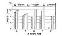
図5に示されるように、CD変動は、界面活性剤の濃度の低い50ppm(CMC以下の濃度)のもので最も小さく、界面活性剤濃度の高い300ppm(CMC以上)で大きくなっている。また、図6に示されるように、析出系欠陥数は、界面活性剤の濃度が100ppm以下の場合には、界面活性剤A〜Eのいずれを用いても、リンス液として純水を用いた場合と比較して、大きくその数が低下していることがわかる。しかしながら、界面活性剤Aでは100ppm以上で、界面活性剤B〜Dでは300ppmで、リンス液として純水を用いた場合と比較して、より多くの析出系欠陥が測定される結果となった。これは、水溶液中に発生したミセルの影響と考えられる。また、同じ300ppmの濃度でも界面活性剤A〜Eで析出系欠陥数に差があるのは、その濃度でのミセルの形成のしやすさが関係しているものと考えられる。 As shown in FIG. 5, the CD fluctuation is the smallest at a low surfactant concentration of 50 ppm (concentration of CMC or less), and is large at a high surfactant concentration of 300 ppm (CMC or more). Further, as shown in FIG. 6, the number of defects in the precipitation system used pure water as the rinsing liquid when any of the surfactants A to E was used when the concentration of the surfactant was 100 ppm or less. Compared to the case, it can be seen that the number is greatly reduced. However, the surfactant A was 100 ppm or more, and the surfactants B to D were 300 ppm. Compared to the case where pure water was used as the rinse liquid, more precipitation defects were measured. This is considered to be the effect of micelles generated in the aqueous solution. The difference in the number of precipitation defects between the surfactants A to E even at the same concentration of 300 ppm is considered to be related to the ease of formation of micelles at that concentration.
これら図5および図6に示される結果によれば、CD変動を抑制し、かつ、析出系欠陥の発生を抑制する観点から、リンス液における界面活性剤濃度はCMC以下とすべきことがわかった。一方、リンス液における界面活性剤の濃度が極端に低いと、水溶液の表面張力が低下しないために、ウエハWに供給されたリンス液をウエハWから振り切る際にパターン倒れが生ずるおそれがあり、また、CD変動および析出系欠陥の発生の抑制効果が得られなくなる。したがって、このパターン倒れを防止する観点をも踏まえると、リンス液における界面活性剤の濃度は、CMC近傍であって、水溶液にミセルが発生しない濃度とすることが好ましい。界面活性剤A〜Eでは、特に界面活性剤Eを用いることが好ましく、その濃度は、50ppmまたはその前後とすることが好ましいことがわかる。 According to the results shown in FIG. 5 and FIG. 6, it was found that the surfactant concentration in the rinsing liquid should be CMC or less from the viewpoint of suppressing CD fluctuation and suppressing the occurrence of precipitation defects. . On the other hand, if the concentration of the surfactant in the rinsing liquid is extremely low, the surface tension of the aqueous solution does not decrease, so that there is a risk of pattern collapse when the rinsing liquid supplied to the wafer W is shaken off from the wafer W. In addition, the effect of suppressing the CD fluctuation and the occurrence of precipitation defects cannot be obtained. Therefore, considering the viewpoint of preventing this pattern collapse, it is preferable that the concentration of the surfactant in the rinsing liquid is in the vicinity of CMC and does not generate micelles in the aqueous solution. In the surfactants A to E, it is found that the surfactant E is particularly preferably used, and the concentration is preferably 50 ppm or around that.
図7に、現像処理の後に界面活性剤A〜Cの100ppm濃度の水溶液を用いてリンス処理を行った場合の、界面活性剤の分子量とCD変動との関係を表すグラフを示す。また、図8に、現像処理の後に界面活性剤A〜Cの100ppm濃度の水溶液を用いてリンス処理を行った場合の、界面活性剤の分子量と析出系欠陥数との関係を表すグラフを示す。図7および図8に示されるように、界面活性剤の分子量が大きくなるとCD変動が抑えられ、また析出系欠陥数も低下することがわかった。 FIG. 7 shows a graph showing the relationship between the molecular weight of the surfactant and the CD variation when the rinse treatment is performed using an aqueous solution of 100 ppm concentration of the surfactants A to C after the development processing. FIG. 8 is a graph showing the relationship between the molecular weight of the surfactant and the number of precipitation defects when the rinse treatment is performed using an aqueous solution of 100 ppm concentration of surfactants A to C after the development treatment. . As shown in FIGS. 7 and 8, it was found that as the molecular weight of the surfactant increases, CD fluctuation is suppressed and the number of precipitation defects is also reduced.
このことから、界面活性剤の分子量は、純水に溶解する範囲で大きいことが好ましいことがわかるが、その中でも界面活性剤の分子量としては、図6に示す純水を用いたリンス処理による析出系欠陥数である約3500を下回る値、つまり1280以上であることが望ましいと判断される。また、界面活性剤A〜Eは基本的に親水基部の分子量はほぼ同じであることから、表1と照合して、疎水基の炭素数は14以上であることが好ましいと判断される。なお、親水基部の重合度には分布があるために、界面活性剤A〜Eの分子量の差は各疎水基の分子量の差と完全には一致しない。 From this, it can be seen that the molecular weight of the surfactant is preferably large in the range that dissolves in pure water. Among them, the molecular weight of the surfactant is the precipitation by rinsing treatment using pure water shown in FIG. It is determined that a value less than about 3500, which is the number of system defects, that is, 1280 or more is desirable. Further, since the surfactants A to E basically have the same molecular weight of the hydrophilic group, it is judged that the hydrophobic group preferably has 14 or more carbon atoms in comparison with Table 1. In addition, since the degree of polymerization of the hydrophilic group has a distribution, the difference in the molecular weight of the surfactants A to E does not completely match the difference in the molecular weight of each hydrophobic group.
図9に、現像処理の後に界面活性剤C・Dの濃度が100ppmの水溶液を用いてリンス処理を行った場合のCD変動を表すグラフを示す。また、図10に、現像処理の後に界面活性剤C・Dの濃度が100ppmの水溶液を用いてリンス処理を行った場合の析出系欠陥数を表すグラフを示す。図9および図10に示されるように、界面活性剤Cの方が界面活性剤DよりもCD変動が抑えられ、また析出系欠陥数も低下していることがわかる。 FIG. 9 is a graph showing the CD fluctuation when the rinse treatment is performed using an aqueous solution having a surfactant C · D concentration of 100 ppm after the development treatment. FIG. 10 is a graph showing the number of precipitation defects when the rinse treatment is performed using an aqueous solution having a surfactant C · D concentration of 100 ppm after the development treatment. As shown in FIGS. 9 and 10, it can be seen that the surfactant C has less CD variation than the surfactant D, and the number of precipitation defects is also reduced.
界面活性剤Cと界面活性剤Dとの違いは、疎水基における二重結合の有無であるので、図9および図10に示す結果は、疎水基の二重結合がレジストパターンを溶解することによって生じたものと考えられる。このことから、リンス液には、疎水基が二重結合を含まず、単結合のみからなる界面活性剤を用いることが好ましいことが明らかとなった。なお、疎水基に三重結合を有する界面活性剤は、二重結合を有する界面活性剤と同様の性質を有すると考えられ、リンス液に含有させないことが好ましいと考えられる。 Since the difference between the surfactant C and the surfactant D is the presence or absence of a double bond in the hydrophobic group, the results shown in FIGS. 9 and 10 show that the double bond of the hydrophobic group dissolves the resist pattern. It is thought to have occurred. From this, it became clear that it is preferable to use a surfactant whose hydrophobic group does not contain a double bond and consists only of a single bond in the rinse solution. The surfactant having a triple bond in the hydrophobic group is considered to have the same properties as the surfactant having a double bond, and it is preferable that the surfactant is not contained in the rinse liquid.
上述の通り、図4〜図10に示した結果から、界面活性剤を含有するリンス液では、界面活性剤の濃度がCMC以下であること、界面活性剤の分子量が大きく(好ましくは1280以上)、疎水基の炭素数が14以上であること、疎水基に二重結合が含まれないこと、の3つ条件のいずれかを満たすことで、CD変動および析出系欠陥の発生が抑制される。リンス液は、これら3つ条件を同時に満足していることが、最も好ましい。 As described above, from the results shown in FIGS. 4 to 10, in the rinse liquid containing the surfactant, the surfactant concentration is CMC or less, and the surfactant has a large molecular weight (preferably 1280 or more). By satisfying any one of the three conditions that the number of carbon atoms of the hydrophobic group is 14 or more and that the hydrophobic group does not include a double bond, the CD fluctuation and the occurrence of precipitation defects are suppressed. It is most preferable that the rinse liquid satisfies these three conditions at the same time.
なお、界面活性剤溶液タンク55に貯留された界面活性剤溶液に界面活性剤のミセルが生成すると、そのような界面活性剤溶液を純水で希釈しても、ミセルが完全に分解してミセルを構成していた界面活性剤が純水に溶解した状態にならないおそれがある。このため、界面活性剤溶液タンク55に貯留される界面活性剤溶液の濃度をCMC以下とすることが望ましい。 When surfactant micelles are generated in the surfactant solution stored in the
リンス液に溶解される界面活性剤はポリエチレングリコールソルビタン脂肪酸エステルに限定されるものではなく、その他のポリエチレングリコール系の界面活性剤、具体的には、下記の化2式に示すポリエチレングリコール直鎖アルキルエーテル、下記の化3式に示すポリエチレングリコール脂肪酸エステル、下記の化4式に示す直鎖アルキル付加型のポリエチレングリコールフェニルエーテル、下記の化5式に示す分岐鎖アルキル付加型のポリエチレングリコールフェニルエーテルでも、上述した界面活性剤濃度や疎水基の炭素数等の条件を満たすことで、ポリエチレングリコールソルビタン脂肪酸エステルを用いた場合と同じ効果が得られる。また、下記の化6式に示すアセチレングリコール系の界面活性剤であるEO付加型のアセチレングリコールについても同様である。なお、化2式〜化6式では、R2〜R5が疎水基を示している。 The surfactant dissolved in the rinsing liquid is not limited to polyethylene glycol sorbitan fatty acid ester, but other polyethylene glycol surfactants, specifically, polyethylene glycol linear alkyl represented by the following chemical formula 2 Ether, polyethylene glycol fatty acid ester represented by the following
次に、現像処理装置(DEV)における現像処理の動作について説明する。この現像処理では、勿論、上述した界面活性剤を所定濃度含有するリンス液がリンス処理に用いられる。 Next, the development processing operation in the development processing apparatus (DEV) will be described. In this development processing, of course, a rinsing solution containing a predetermined concentration of the above-described surfactant is used for the rinsing processing.
図11に第1の現像プロセスを示すフローチャートを示す。最初に、所定のパターンが露光され、ポストエクスポージャーベーク処理および冷却処理されたウエハWが、ウエハ搬送装置の搬送アームTによってカップCPの真上まで搬送され、昇降ピン5に受け渡され、スピンチャック2上に載置され、真空吸着される(STEP1)。 FIG. 11 is a flowchart showing the first development process. First, a wafer W that has been exposed to a predetermined pattern, post-exposure bake processing and cooling processing is transferred to a position just above the cup CP by the transfer arm T of the wafer transfer device, and is transferred to the lift pins 5 to be transferred to the spin chuck. 2 and vacuum-adsorbed (STEP 1).
次いで、現像液供給ノズル11がウエハWの中心の上方に移動し、この現像液供給ノズル11から現像液が帯状に吐出されながら、ウエハWが1/2回転以上、例えば1回転されることにより、現像液がウエハW全面に塗布され、現像液パドルが形成される(STEP2)。なお、現像液供給ノズル11をガイドレール21に沿ってスキャンしながら現像液を吐出してもよい。 Next, the developing
このようにして現像液をウエハW上に塗布した状態で適宜の時間、例えば60秒間静止させることにより現像を進行させる(STEP3)。この際に、現像液供給ノズル11をカップCP外に待避させ、リンス液供給ノズル13のノズルアーム18を移動させて、リンス液供給ノズル13をウエハWの中心の上方に位置させる(STEP4)。 In this way, the developing solution is allowed to stand for an appropriate time, for example, 60 seconds with the developer applied on the wafer W (STEP 3). At this time, the
現像反応を進行させるための所定時間が経過した後に、ウエハWをスピンチャック2により回転させ、現像液を振り切る(STEP5)。次いで、リンス液供給ノズル13から、上述した界面活性剤を所定量含有するリンス液を帯状に吐出しながら、ウエハWを所定の回転数(例えば、500〜2000rpm)で回転させて、リンス液によるリンス処理を行う(STEP6)。ここで、リンス液の供給前には、待避位置においてリンス液供給ノズル13のダミーディスペンスを行って、リンス液供給ノズル13に付着した界面活性剤の残渣等がウエハWに供給されないようにすることが望ましい。これによりリンス液に起因するパーティクルの発生をより確実に排除することができる。 After a predetermined time for advancing the development reaction, the wafer W is rotated by the spin chuck 2 and the developer is shaken off (STEP 5). Next, the wafer W is rotated at a predetermined rotation speed (for example, 500 to 2000 rpm) while discharging a rinse liquid containing a predetermined amount of the above-described surfactant from the rinse
リンス液供給ノズル13を用いることにより、リンス液を低インパクトでウエハWに短時間で供給することができ、これによりCD変動の抑制効果を高めることができる。なお、このリンス処理は、ウエハWを静止させた状態またはウエハWを所定の回転数(例えば、1000rpm以下)で回転させた状態で、リンス液供給ノズル13をガイドレール30に沿ってスキャンさせることによって行ってもよい。 By using the rinsing
所定時間、リンス液を供給した後に、リンス液供給ノズル13をカップCP外に待避させ、ウエハWの回転数を上昇させて、このリンス液を広げるとともにリンス液を振り切って、ウエハWを乾燥させる(STEP7)。この工程は、最初に、ウエハWの回転数を300rpm超1000rpm未満、例えば500rpmとし、5〜15秒、例えば10秒間行い、引き続き、ウエハWの回転数を1000〜4000rpm、例えば2000rpmとし、10〜20秒間、例えば15秒間が行うことが好ましい。このようにしてリンス液をウエハWから振り切ってウエハWをスピン乾燥することによって、パターン倒れの発生を効果的に抑制することができる。 After supplying the rinsing liquid for a predetermined time, the rinsing
こうして乾燥処理されたウエハWは、昇降ピン5によってスピンチャック2の上に持ち上げられ、ウエハ搬送装置の搬送アームTによって現像処理装置(DEV)から搬出され(STEP8)、ポストベーク処理が施される。 The wafer W thus dried is lifted onto the spin chuck 2 by the elevating
このような第1の現像プロセスでは、先に説明した所定の条件を満たす界面活性剤を所定濃度含有するリンス液を用いることによって、純水によるリンス処理を行わなくとも、パーティクル等の析出系欠陥の発生が抑制され、また、CD変動およびレジストパターンの溶解が抑制され、さらにパターン倒れの発生も防止することができる。これによって、高清浄性で精密なレジストパターンを得ることができる。 In such a first development process, by using a rinsing liquid containing a predetermined concentration of the surfactant that satisfies the predetermined conditions described above, precipitation defects such as particles can be obtained without rinsing with pure water. Is suppressed, CD variation and resist pattern dissolution are suppressed, and pattern collapse can be prevented. Thereby, a highly clean and precise resist pattern can be obtained.
次に、第2の現像プロセスについて、図12に示すフローチャートを参照しながら説明する。最初に、第1の現像プロセスと同様にして、露光処理されたウエハWがスピンチャック2に真空吸着される(STEP101)。次いで、現像液供給ノズル11がウエハWの中心の上方に移動し、この現像液供給ノズル11から現像液が帯状に吐出されながら、ウエハWが1/2回転以上、例えば1回転されることにより、現像液がウエハW全面に塗布され、現像液パドルが形成される(STEP102)。 Next, the second development process will be described with reference to the flowchart shown in FIG. First, as in the first development process, the exposed wafer W is vacuum-sucked to the spin chuck 2 (STEP 101). Next, the developing
このようにして現像液をウエハW上に塗布した状態で適宜の時間、例えば60秒間静止させることにより現像を進行させる(STEP103)。この際に、現像液供給ノズル11のノズルアーム14をカップCP外に待避させて、純水供給ノズル12を移動させて、純水供給ノズル12をウエハWの中心の上方に位置させる(STEP104)。 In this way, development is advanced by allowing the developer to be applied on the wafer W for a suitable time, for example, 60 seconds (STEP 103). At this time, the
現像反応を進行させるための所定時間が経過した後に、ウエハWをスピンチャック2により回転させ、現像液を振り切る(STEP105)。次いで、純水によるリンス処理を行う(STEP106)。この際には、ウエハWの回転数が500〜2000rpm、例えば1000rpmになった時点でその回転数を維持しながら純水を2秒間以上、例えば5秒間供給し、次いで、純水を供給したままウエハWの回転数を100〜1000rpm、例えば500rpmまで低下させ、その回転数で2秒間以上、例えば10秒間維持することが好ましい。STEP106でのウエハWの回転数については、処理するウエハWのサイズに合わせて最適な値が選択される。 After a predetermined time for advancing the development reaction, the wafer W is rotated by the spin chuck 2 and the developer is shaken off (STEP 105). Next, rinsing with pure water is performed (STEP 106). At this time, when the rotation speed of the wafer W reaches 500 to 2000 rpm, for example, 1000 rpm, pure water is supplied for 2 seconds or more, for example, 5 seconds while maintaining the rotation speed, and then the pure water is supplied. It is preferable to reduce the rotation speed of the wafer W to 100 to 1000 rpm, for example, 500 rpm, and maintain the rotation speed for 2 seconds or more, for example, 10 seconds. As for the rotation speed of the wafer W in STEP 106, an optimum value is selected according to the size of the wafer W to be processed.
なお、現像液を振り切った後に直接純水を供給するとウエハW上のレジスト膜に通常のリンスでは除去し難い難溶化層が形成される場合があるが、この場合には、純水のみのリンスに先立って純水+現像液のリンスを行うことによりレジスト膜上の難溶化層の生成を防止することができる。 If pure water is supplied directly after the developer is shaken off, a resist layer on the wafer W may form a hardly soluble layer that is difficult to remove by ordinary rinsing. In this case, rinsing with pure water only is performed. Prior to the rinsing, pure water + developer rinsing is performed to prevent formation of a poorly soluble layer on the resist film.
このような純水リンスの後、純水供給ノズル12をカップCP外に待避させ、リンス液供給ノズル13のノズルアーム18を移動させて、リンス液供給ノズル13をウエハWのほぼ中央上方に位置させる(STEP107)。そして、ウエハWを好ましくは500rpm以下、例えば100rpmで回転させながら、上述した界面活性剤を所定量含有するリンス液をウエハWに供給して、レジスト膜上の純水および残留している現像液の大部分をリンス液に置換する(STEP108)。すなわち、レジスト膜の表面がリンス液に置換された状態となる。このように界面活性剤入りのリンス液供給の際にウエハWを500rpm以下で回転させることにより、リンス液の良好な置換性を維持しつつ飛散するリンス液の量を少なくすることができるため、リンス液の使用量を極力少なくすることができる。 After such pure water rinsing, the pure
こうしてウエハW上にリンス液を供給した後に、ウエハWの回転数を上昇させて、リンス液を広げるとともにリンス液を振り切って、ウエハWを乾燥させる(STEP109)。この工程は、最初に、ウエハWの回転数を300rpm超1000rpm未満、例えば500rpmとし、5〜15秒、例えば10秒間行い、引き続き、ウエハWの回転数を1000〜4000rpm、例えば2000rpmとし、10〜20秒間、例えば15秒間が行うことが好ましい。このようにしてリンス液をウエハWから振り切ってウエハWをスピン乾燥することによって、パターン倒れの発生を効果的に抑制することができる。 After supplying the rinsing liquid onto the wafer W in this way, the number of rotations of the wafer W is increased, the rinsing liquid is spread and the rinsing liquid is shaken off, and the wafer W is dried (STEP 109). In this step, first, the rotation speed of the wafer W is set to more than 300 rpm and less than 1000 rpm, for example, 500 rpm, for 5 to 15 seconds, for example, 10 seconds, and subsequently, the rotation speed of the wafer W is set to 1000 to 4000 rpm, for example, 2000 rpm. It is preferable to carry out for 20 seconds, for example, 15 seconds. In this way, the rinse of the rinse liquid from the wafer W and spin drying of the wafer W can effectively suppress the occurrence of pattern collapse.
こうして乾燥処理されたウエハWは、昇降ピン5によってスピンチャック2の上に持ち上げられ、ウエハ搬送装置の搬送アームTによって現像処理装置(DEV)から搬出され(STEP110)、ポストベーク処理が施される。 The wafer W thus dried is lifted onto the spin chuck 2 by the elevating
このような第2の現像プロセスを用いた場合でも、先に説明した所定の条件を満たす界面活性剤を所定濃度含有するリンス液を用いることによって、純水によるリンス処理を行わなくとも、パーティクル等の析出系欠陥の発生が抑制され、また、CD変動およびレジストパターンの溶解が抑制される。さらに界面活性剤を所定濃度含むリンス液がウエハWに供給された後に、これを振り切ってウエハWを乾燥させるために、パターン倒れの発生も防止することができる。 Even when such a second development process is used, particles or the like can be obtained without using a rinse with pure water by using a rinse solution containing a predetermined concentration of the surfactant that satisfies the predetermined conditions described above. The occurrence of precipitation defects is suppressed, and the CD variation and resist pattern dissolution are suppressed. Further, after the rinse liquid containing a predetermined concentration of the surfactant is supplied to the wafer W, the wafer W is shaken off to dry the wafer W, so that the occurrence of pattern collapse can be prevented.
図13は第3〜第6の現像プロセスの概略の処理フローを簡略化して示す図である。このうち第3,第5,第6の現像プロセスは、図13に示されるように、最終的に純水がウエハWの表面に供給された状態で、ウエハWからこの純水を振り切ってウエハWを乾燥させるプロセスであるために、純水の表面張力によるパターン倒れの問題が問題とならないレジストパターンの場合に用いられるプロセスである。なお、図13は先に説明した第1の現像プロセスおよび第2の現像プロセスの処理フローを併記している。 FIG. 13 is a diagram showing a simplified processing flow of the third to sixth development processes. Among these, the third, fifth, and sixth development processes are performed by shaking off the pure water from the wafer W in a state where the pure water is finally supplied to the surface of the wafer W as shown in FIG. Since this is a process of drying W, it is a process used in the case of a resist pattern in which the problem of pattern collapse due to the surface tension of pure water does not matter. FIG. 13 shows the processing flow of the first development process and the second development process described above.
図13に示されるように、第3の現像プロセスは、現像液による現像処理、界面活性剤を含有するリンス液によるリンス処理、純水によるリンス処理、乾燥処理の順序で行われる。第4の現像プロセスは、現像液による現像処理、純水によるリンス処理、界面活性剤を含有するリンス液によるリンス処理、純水によるリンス処理、乾燥処理の順序で行われる。第5の現像プロセスは、現像液による現像処理、界面活性剤を含有するリンス液によるリンス処理、現像液による現像処理、純水によるリンス処理、乾燥処理の順序で行われる。第6の現像プロセスは、界面活性剤を含有するリンス液によるリンス処理、乾燥処理、現像液による現像処理、純水によるリンス処理、乾燥処理の順序で行われる。これらのプロセスによっても、析出系欠陥の発生やCD変動、レジストパターンを溶解を抑制することができる。 As shown in FIG. 13, the third development process is performed in the order of development processing with a developer, rinsing processing with a rinsing liquid containing a surfactant, rinsing processing with pure water, and drying processing. The fourth development process is performed in the order of development processing with a developing solution, rinsing processing with pure water, rinsing processing with a rinsing liquid containing a surfactant, rinsing processing with pure water, and drying processing. The fifth development process is performed in the order of development with a developer, rinse with a rinse containing a surfactant, development with a developer, rinse with pure water, and drying. The sixth development process is performed in the order of a rinse treatment with a rinse solution containing a surfactant, a drying treatment, a development treatment with a developer, a rinse treatment with pure water, and a drying treatment. Also by these processes, generation of precipitation defects, CD fluctuation, and dissolution of the resist pattern can be suppressed.
なお、本発明は上記実施の形態に限定されず、種々の変形が可能である。例えば、上記実施の形態では、水系洗浄液として純水を例示したが、純水に他の物質が多少添加したものであってもよい。また、リンス液供給ノズル13として帯状にリンス液を吐出する形態のものを示したが、リンス液供給ノズル13としては、純水供給ノズル12と同様のストレートタイプのものを用いてもよい。この場合には、必要なリンス液流量が得られる範囲で、できるだけウエハWへのインパクトが小さくなる構造のものを用いることが好ましい。 In addition, this invention is not limited to the said embodiment, A various deformation | transformation is possible. For example, in the above-described embodiment, pure water is exemplified as the aqueous cleaning liquid. However, pure water may be added with other substances to some extent. Moreover, although the thing of the form which discharges a rinse liquid in the strip | belt shape was shown as the rinse
さらに、上記実施の形態では本発明を半導体ウエハの現像処理に適用したが、これに限らず、微細なレジストパターンが形成される基板であれば、液晶表示装置(LCD)用基板等、他の基板の現像処理にも適用することができる。さらに、本発明の範囲を逸脱しない限り、上記実施の形態の構成要素を適宜組み合わせたもの、あるいは上記実施の形態の構成要素を一部取り除いたものも本発明の範囲内である。 Further, in the above embodiment, the present invention is applied to the development processing of a semiconductor wafer. However, the present invention is not limited to this, and any other substrate such as a liquid crystal display (LCD) substrate may be used as long as it is a substrate on which a fine resist pattern is formed. The present invention can also be applied to substrate development processing. Further, a combination of the constituent elements of the above-described embodiment as appropriate or a part of the constituent elements of the above-described embodiment removed is also within the scope of the present invention without departing from the scope of the present invention.
1;筐体
2;スピンチャック
11;現像液供給ノズル
12;純水供給ノズル
13;リンス液供給ノズル
52;純水供給配管
54;ミキシングバルブ
56;界面活性剤溶液供給配管
DEV;現像処理装置
W;半導体ウエハDESCRIPTION OF SYMBOLS 1; Housing | casing 2;
Claims (20)
Translated fromJapanese基板上の露光後のレジスト膜に現像液を塗布し、現像を進行させる工程と、
現像後の基板から現像液を振り切る工程と、
基板上に臨界ミセル濃度以下のポリエチレングリコール系またはアセチレングリコール系の界面活性剤を含有するリンス液を供給する工程と、
前記基板を回転させて基板上の前記界面活性剤を含有するリンス液を広げるとともに振り切り、基板を乾燥させる工程と、
を有することを特徴とする現像処理方法。A development processing method for developing an exposure pattern after exposing a resist film formed on a substrate to a predetermined pattern,
Applying a developing solution to the resist film after exposure on the substrate and proceeding with development;
Shaking off the developer from the substrate after development;
Supplying a rinsing liquid containing a polyethylene glycol-based or acetylene glycol-based surfactant having a critical micelle concentration or less on the substrate;
Rotating the substrate to spread the rinse solution containing the surfactant on the substrate and shaking it off, and drying the substrate;
A development processing method characterized by comprising:
基板上の露光後のレジスト膜に現像液を塗布し、現像を進行させる工程と、
現像後の基板から現像液を振り切る工程と、
基板上に臨界ミセル濃度以下のポリエチレングリコール系またはアセチレングリコール系の界面活性剤を含有するリンス液を供給する工程と、
基板に純水を供給して、基板上のリンス液を純水に置換する工程と、
基板を回転させて基板上の純水を広げるとともに振り切り、基板を乾燥させる工程と、
を有することを特徴とする現像処理方法。A development processing method for developing an exposure pattern after exposing a resist film formed on a substrate to a predetermined pattern,
Applying a developing solution to the resist film after exposure on the substrate and proceeding with development;
Shaking off the developer from the substrate after development;
Supplying a rinsing liquid containing a polyethylene glycol-based or acetylene glycol-based surfactant having a critical micelle concentration or less on the substrate;
Supplying pure water to the substrate and replacing the rinse liquid on the substrate with pure water;
Rotating the substrate to spread pure water on the substrate and shaking it off, drying the substrate,
A development processing method characterized by comprising:
基板上の露光後のレジスト膜に現像液を塗布し、現像を進行させる工程と、
現像後の基板から現像液を振り切る工程と、
基板上に純水を供給する工程と、
基板上に臨界ミセル濃度以下のポリエチレングリコール系またはアセチレングリコール系の界面活性剤を含有するリンス液を供給して、基板上の純水を前記リンス液に置換する工程と、
前記基板を回転させて基板上のリンス液を広げるとともに振り切り、基板を乾燥させる工程と、
を有することを特徴とする現像処理方法。A development processing method for developing an exposure pattern after exposing a resist film formed on a substrate to a predetermined pattern,
Applying a developing solution to the resist film after exposure on the substrate and proceeding with development;
Shaking off the developer from the substrate after development;
Supplying pure water on the substrate;
Supplying a rinse solution containing a polyethylene glycol-based or acetylene glycol-based surfactant having a critical micelle concentration or less on the substrate, and replacing the pure water on the substrate with the rinse solution;
Rotating the substrate to spread the rinse liquid on the substrate and shaking it off, drying the substrate;
A development processing method characterized by comprising:
基板上の露光後のレジスト膜に現像液を塗布し、現像を進行させる工程と、
現像後の基板から現像液を振り切る工程と、
基板上に純水を供給する工程と、
基板上に臨界ミセル濃度以下のポリエチレングリコール系またはアセチレングリコール系の界面活性剤を含有するリンス液を供給して、基板上の純水を前記リンス液に置換する工程と、
基板上に純水を供給して、基板上のリンス液を純水に置換する工程と、
基板を回転させて基板上の純水を広げるとともに振り切り、基板を乾燥させる工程と、
を有することを特徴とする現像処理方法。A development processing method for developing an exposure pattern after exposing a resist film formed on a substrate to a predetermined pattern,
Applying a developing solution to the resist film after exposure on the substrate and proceeding with development;
Shaking off the developer from the substrate after development;
Supplying pure water on the substrate;
Supplying a rinse solution containing a polyethylene glycol-based or acetylene glycol-based surfactant having a critical micelle concentration or less on the substrate, and replacing the pure water on the substrate with the rinse solution;
Supplying pure water onto the substrate and replacing the rinse liquid on the substrate with pure water;
Rotating the substrate to spread pure water on the substrate and shaking it off, drying the substrate,
A development processing method characterized by comprising:
基板上の露光後のレジスト膜に現像液を塗布し、現像を進行させる工程と、
現像後の基板から現像液を振り切る工程と、
基板上に臨界ミセル濃度以下のポリエチレングリコール系またはアセチレングリコール系の界面活性剤を含有するリンス液を供給する工程と、
基板からリンス液を振り切る工程と、
基板上に再び現像液を塗布し、現像を進行させる工程と、
現像後の基板から現像液を振り切る工程と、
基板上に純水を供給する工程と、
基板を回転させて基板上の純水を広げるとともに振り切り、基板を乾燥させる工程と、
を有することを特徴とする現像処理方法。A development processing method for developing an exposure pattern after exposing a resist film formed on a substrate to a predetermined pattern,
Applying a developing solution to the resist film after exposure on the substrate and proceeding with development;
Shaking off the developer from the substrate after development;
Supplying a rinsing liquid containing a polyethylene glycol-based or acetylene glycol-based surfactant having a critical micelle concentration or less on the substrate;
Shaking off the rinse liquid from the substrate;
Applying the developer again on the substrate and proceeding with development;
Shaking off the developer from the substrate after development;
Supplying pure water on the substrate;
Rotating the substrate to spread pure water on the substrate and shaking it off, drying the substrate,
A development processing method characterized by comprising:
基板上に臨界ミセル濃度以下のポリエチレングリコール系またはアセチレングリコール系の界面活性剤を含有するリンス液を基板に供給する工程と、
基板から前記リンス液を振り切り、基板を乾燥させる工程と、
基板上に現像液を塗布し、前記レジスト膜の現像を進行させる工程と、
現像後の基板から現像液を振り切る工程と、
基板上に純水を供給する工程と、
基板を回転させて基板上の純水を広げるとともに振り切り、基板を乾燥させる工程と、
を有することを特徴とする現像処理方法。A development processing method for developing an exposure pattern after exposing a resist film formed on a substrate to a predetermined pattern,
Supplying a rinse solution containing a polyethylene glycol-based or acetylene glycol-based surfactant having a critical micelle concentration or less onto the substrate;
Shaking off the rinse liquid from the substrate and drying the substrate;
Applying a developer on the substrate and advancing development of the resist film; and
Shaking off the developer from the substrate after development;
Supplying pure water on the substrate;
Rotating the substrate to spread pure water on the substrate and shaking it off, drying the substrate,
A development processing method characterized by comprising:
Priority Applications (4)
| Application Number | Priority Date | Filing Date | Title |
|---|---|---|---|
| JP2004207574AJP2006030483A (en) | 2004-07-14 | 2004-07-14 | Rinsing method and development processing method |
| PCT/JP2005/010068WO2006006317A1 (en) | 2004-07-14 | 2005-06-01 | Method of rinse treatment, method of development processing and computer-readable storage medium |
| US11/652,497US7419773B2 (en) | 2004-07-14 | 2007-01-12 | Rinsing method and developing method |
| US12/219,838US20090042149A1 (en) | 2004-07-14 | 2008-07-29 | Rinsing method and developing method |
Applications Claiming Priority (1)
| Application Number | Priority Date | Filing Date | Title |
|---|---|---|---|
| JP2004207574AJP2006030483A (en) | 2004-07-14 | 2004-07-14 | Rinsing method and development processing method |
Related Child Applications (1)
| Application Number | Title | Priority Date | Filing Date |
|---|---|---|---|
| JP2009007350ADivisionJP2009122691A (en) | 2009-01-16 | 2009-01-16 | Developing method and developing device |
Publications (1)
| Publication Number | Publication Date |
|---|---|
| JP2006030483Atrue JP2006030483A (en) | 2006-02-02 |
Family
ID=35783673
Family Applications (1)
| Application Number | Title | Priority Date | Filing Date |
|---|---|---|---|
| JP2004207574APendingJP2006030483A (en) | 2004-07-14 | 2004-07-14 | Rinsing method and development processing method |
Country Status (3)
| Country | Link |
|---|---|
| US (2) | US7419773B2 (en) |
| JP (1) | JP2006030483A (en) |
| WO (1) | WO2006006317A1 (en) |
Cited By (3)
| Publication number | Priority date | Publication date | Assignee | Title |
|---|---|---|---|---|
| WO2008047720A1 (en)* | 2006-10-19 | 2008-04-24 | Az Electronic Materials (Japan) K.K. | Solution for treatment of resist substrate after development processing, and method for treatment of resist substrate using the same |
| WO2014181748A1 (en)* | 2013-05-09 | 2014-11-13 | アーゼット・エレクトロニック・マテリアルズ(ルクセンブルグ)ソシエテ・ア・レスポンサビリテ・リミテ | Rinsing liquid for lithography and pattern forming method using same |
| KR20230001961A (en)* | 2021-06-29 | 2023-01-05 | 세메스 주식회사 | Substrate processing method and substrate processing system |
Families Citing this family (9)
| Publication number | Priority date | Publication date | Assignee | Title |
|---|---|---|---|---|
| JP4045180B2 (en)* | 2002-12-03 | 2008-02-13 | Azエレクトロニックマテリアルズ株式会社 | Rinsing liquid for lithography and resist pattern forming method using the same |
| WO2005101468A1 (en)* | 2004-04-13 | 2005-10-27 | Tokyo Electron Limited | Rinse treatment method and development process method |
| JP4514224B2 (en) | 2005-09-28 | 2010-07-28 | 東京エレクトロン株式会社 | Rinse processing method, development processing method, and development apparatus |
| JP5000260B2 (en)* | 2006-10-19 | 2012-08-15 | AzエレクトロニックマテリアルズIp株式会社 | Method for forming fine pattern and resist substrate processing liquid used therefor |
| JP5306755B2 (en)* | 2008-09-16 | 2013-10-02 | AzエレクトロニックマテリアルズIp株式会社 | Substrate processing liquid and resist substrate processing method using the same |
| JP4927158B2 (en) | 2009-12-25 | 2012-05-09 | 東京エレクトロン株式会社 | Substrate processing method, recording medium storing program for executing substrate processing method, and substrate processing apparatus |
| KR20170044968A (en)* | 2015-10-16 | 2017-04-26 | 삼성전자주식회사 | Method of cleaning a substrate and fabrication method of semiconductor device using the same |
| US11626297B2 (en)* | 2016-10-25 | 2023-04-11 | Acm Research (Shanghai), Inc. | Apparatus and method for wet process on semiconductor substrate |
| KR102247828B1 (en)* | 2018-07-23 | 2021-05-04 | 세메스 주식회사 | Substrate treating method and substrate treating apparatus |
Family Cites Families (9)
| Publication number | Priority date | Publication date | Assignee | Title |
|---|---|---|---|---|
| US4381340A (en)* | 1980-08-08 | 1983-04-26 | American Hoechst Corporation | Method of treating lithographic printing plates with 2-propoxyethanol |
| DE3501675A1 (en)* | 1985-01-19 | 1986-07-24 | Merck Patent Gmbh, 6100 Darmstadt | AGENT AND METHOD FOR REMOVING PHOTORESIST AND STRIPPER REMAINS FROM SEMICONDUCTOR SUBSTRATES |
| JPH07142349A (en) | 1993-11-16 | 1995-06-02 | Mitsubishi Electric Corp | Method for preventing collapse of photoresist pattern in development process |
| US6159662A (en)* | 1999-05-17 | 2000-12-12 | Taiwan Semiconductor Manufacturing Company | Photoresist development method with reduced cycle time and improved performance |
| JP3479613B2 (en)* | 1999-06-21 | 2003-12-15 | 東京エレクトロン株式会社 | Development processing method and development processing apparatus |
| TW558736B (en)* | 2000-02-26 | 2003-10-21 | Shipley Co Llc | Method of reducing defects |
| US6692165B2 (en)* | 2001-03-01 | 2004-02-17 | Dainippon Screen Mfg. Co., Ltd. | Substrate processing apparatus |
| JP3511514B2 (en)* | 2001-05-31 | 2004-03-29 | エム・エフエスアイ株式会社 | Substrate purification processing apparatus, dispenser, substrate holding mechanism, substrate purification processing chamber, and substrate purification method using these |
| JP4045180B2 (en)* | 2002-12-03 | 2008-02-13 | Azエレクトロニックマテリアルズ株式会社 | Rinsing liquid for lithography and resist pattern forming method using the same |
- 2004
- 2004-07-14JPJP2004207574Apatent/JP2006030483A/enactivePending
- 2005
- 2005-06-01WOPCT/JP2005/010068patent/WO2006006317A1/enactiveApplication Filing
- 2007
- 2007-01-12USUS11/652,497patent/US7419773B2/ennot_activeExpired - Fee Related
- 2008
- 2008-07-29USUS12/219,838patent/US20090042149A1/ennot_activeAbandoned
Cited By (8)
| Publication number | Priority date | Publication date | Assignee | Title |
|---|---|---|---|---|
| WO2008047720A1 (en)* | 2006-10-19 | 2008-04-24 | Az Electronic Materials (Japan) K.K. | Solution for treatment of resist substrate after development processing, and method for treatment of resist substrate using the same |
| JP2008102343A (en)* | 2006-10-19 | 2008-05-01 | Az Electronic Materials Kk | Developed resist substrate processing solution and resist substrate processing method using the same |
| WO2014181748A1 (en)* | 2013-05-09 | 2014-11-13 | アーゼット・エレクトロニック・マテリアルズ(ルクセンブルグ)ソシエテ・ア・レスポンサビリテ・リミテ | Rinsing liquid for lithography and pattern forming method using same |
| JP2014219577A (en)* | 2013-05-09 | 2014-11-20 | Azエレクトロニックマテリアルズマニュファクチャリング株式会社 | Rinse liquid for lithography and pattern formation method using the same |
| US9494867B2 (en) | 2013-05-09 | 2016-11-15 | Az Electronic Materials (Luxembourg) S.A.R.L. | Rinsing liquid for lithography and pattern forming method using same |
| KR20230001961A (en)* | 2021-06-29 | 2023-01-05 | 세메스 주식회사 | Substrate processing method and substrate processing system |
| US12198923B2 (en) | 2021-06-29 | 2025-01-14 | Semes Co., Ltd. | Substrate processing method and substrate processing system |
| KR102774680B1 (en)* | 2021-06-29 | 2025-03-04 | 세메스 주식회사 | Substrate processing method and substrate processing system |
Also Published As
| Publication number | Publication date |
|---|---|
| US20090042149A1 (en) | 2009-02-12 |
| US7419773B2 (en) | 2008-09-02 |
| WO2006006317A1 (en) | 2006-01-19 |
| US20070134601A1 (en) | 2007-06-14 |
Similar Documents
| Publication | Publication Date | Title |
|---|---|---|
| US7419773B2 (en) | Rinsing method and developing method | |
| US8398320B2 (en) | Non-transitory storage medium for rinsing or developing sequence | |
| JP5390808B2 (en) | Substrate processing apparatus and substrate processing method | |
| KR100891062B1 (en) | Substrate processing method and substrate processing apparatus | |
| CN1289970C (en) | Developing method | |
| KR100822511B1 (en) | Substrate Processing Apparatus and Substrate Processing Method | |
| JP4866165B2 (en) | Substrate development processing method and substrate development processing apparatus | |
| JP4812563B2 (en) | Substrate processing method and substrate processing apparatus | |
| JP2007157898A (en) | Substrate cleaning method, substrate cleaning device, control program, and computer readable storage medium | |
| JP4514224B2 (en) | Rinse processing method, development processing method, and development apparatus | |
| JP4684858B2 (en) | Rinse processing method, development processing method, development processing apparatus, control program, and computer-readable storage medium | |
| JP5016525B2 (en) | Substrate processing method and substrate processing apparatus | |
| JP2008041722A (en) | Method and device for processing substrate | |
| JP2009212408A (en) | Method and apparatus for processing substrate | |
| CN1841213B (en) | Developing method and method of manufacturing a semiconductor device | |
| JP4504229B2 (en) | Rinse processing method and development processing method | |
| JP2006059918A (en) | Development processing method | |
| JP2009122691A (en) | Developing method and developing device | |
| JP4199102B2 (en) | Substrate processing method, substrate processing system, and developer supply nozzle | |
| JP4554236B2 (en) | Liquid supply mechanism and liquid supply method | |
| JP2004014869A (en) | Developing device | |
| JP4723631B2 (en) | Development processing method, program, computer storage medium, and development processing apparatus | |
| JP4477019B2 (en) | Substrate processing method | |
| JP2019046928A (en) | Substrate processing method and substrate processing apparatus | |
| JP4519751B2 (en) | Substrate development method and substrate development apparatus |
Legal Events
| Date | Code | Title | Description |
|---|---|---|---|
| A621 | Written request for application examination | Free format text:JAPANESE INTERMEDIATE CODE: A621 Effective date:20060627 | |
| A977 | Report on retrieval | Free format text:JAPANESE INTERMEDIATE CODE: A971007 Effective date:20081017 | |
| A131 | Notification of reasons for refusal | Free format text:JAPANESE INTERMEDIATE CODE: A131 Effective date:20081118 | |
| A521 | Written amendment | Free format text:JAPANESE INTERMEDIATE CODE: A523 Effective date:20090116 | |
| A131 | Notification of reasons for refusal | Free format text:JAPANESE INTERMEDIATE CODE: A131 Effective date:20091020 | |
| A521 | Written amendment | Free format text:JAPANESE INTERMEDIATE CODE: A523 Effective date:20091217 | |
| A02 | Decision of refusal | Free format text:JAPANESE INTERMEDIATE CODE: A02 Effective date:20100309 |