JP2006026013A - Biomedical tissue suturing method and apparatus - Google Patents
Biomedical tissue suturing method and apparatusDownload PDFInfo
- Publication number
- JP2006026013A JP2006026013AJP2004207740AJP2004207740AJP2006026013AJP 2006026013 AJP2006026013 AJP 2006026013AJP 2004207740 AJP2004207740 AJP 2004207740AJP 2004207740 AJP2004207740 AJP 2004207740AJP 2006026013 AJP2006026013 AJP 2006026013A
- Authority
- JP
- Japan
- Prior art keywords
- anvil
- staple
- endoscope
- needle
- suture
- Prior art date
- Legal status (The legal status is an assumption and is not a legal conclusion. Google has not performed a legal analysis and makes no representation as to the accuracy of the status listed.)
- Granted
Links
- 238000000034methodMethods0.000titledescription6
- 238000003780insertionMethods0.000claimsabstractdescription129
- 230000037431insertionEffects0.000claimsabstractdescription129
- 238000001514detection methodMethods0.000claimsdescription10
- 230000002093peripheral effectEffects0.000claimsdescription10
- 230000000149penetrating effectEffects0.000claimsdescription5
- 210000001519tissueAnatomy0.000description84
- 210000002429large intestineAnatomy0.000description21
- 230000004308accommodationEffects0.000description20
- 210000000813small intestineAnatomy0.000description19
- 210000002784stomachAnatomy0.000description19
- 230000003872anastomosisEffects0.000description15
- 210000000056organAnatomy0.000description12
- 210000003238esophagusAnatomy0.000description9
- 210000000683abdominal cavityAnatomy0.000description5
- 238000003860storageMethods0.000description5
- 238000004804windingMethods0.000description5
- 238000013459approachMethods0.000description4
- 230000003902lesionEffects0.000description4
- 210000003815abdominal wallAnatomy0.000description3
- 239000000470constituentSubstances0.000description3
- 238000005520cutting processMethods0.000description3
- 230000000694effectsEffects0.000description3
- 210000001035gastrointestinal tractAnatomy0.000description3
- 230000007246mechanismEffects0.000description3
- 230000006378damageEffects0.000description2
- 238000010586diagramMethods0.000description2
- 238000001125extrusionMethods0.000description2
- 208000021302gastroesophageal reflux diseaseDiseases0.000description2
- 210000003205muscleAnatomy0.000description2
- 230000003287optical effectEffects0.000description2
- 208000000689peptic esophagitisDiseases0.000description2
- 230000009467reductionEffects0.000description2
- 239000004065semiconductorSubstances0.000description2
- 238000001356surgical procedureMethods0.000description2
- 230000000007visual effectEffects0.000description2
- 230000009471actionEffects0.000description1
- 210000000436anusAnatomy0.000description1
- 230000005540biological transmissionEffects0.000description1
- 210000002318cardiaAnatomy0.000description1
- 238000006243chemical reactionMethods0.000description1
- 230000023077detection of light stimulusEffects0.000description1
- 230000030808detection of mechanical stimulus involved in sensory perception of soundEffects0.000description1
- 230000005251gamma rayEffects0.000description1
- 230000002496gastric effectEffects0.000description1
- 230000000968intestinal effectEffects0.000description1
- 238000005304joiningMethods0.000description1
- 230000007774longtermEffects0.000description1
- HWYHZTIRURJOHG-UHFFFAOYSA-NluminolChemical compoundO=C1NNC(=O)C2=C1C(N)=CC=C2HWYHZTIRURJOHG-UHFFFAOYSA-N0.000description1
- 238000012986modificationMethods0.000description1
- 230000004048modificationEffects0.000description1
- 230000008520organizationEffects0.000description1
- 238000002360preparation methodMethods0.000description1
- 238000003825pressingMethods0.000description1
- 238000012545processingMethods0.000description1
- 230000005855radiationEffects0.000description1
- 230000000452restraining effectEffects0.000description1
- 238000000926separation methodMethods0.000description1
- 239000000126substanceSubstances0.000description1
- 208000024891symptomDiseases0.000description1
- 230000001225therapeutic effectEffects0.000description1
Images


Classifications
- A—HUMAN NECESSITIES
- A61—MEDICAL OR VETERINARY SCIENCE; HYGIENE
- A61B—DIAGNOSIS; SURGERY; IDENTIFICATION
- A61B17/00—Surgical instruments, devices or methods
- A61B17/11—Surgical instruments, devices or methods for performing anastomosis; Buttons for anastomosis
- A61B17/115—Staplers for performing anastomosis, e.g. in a single operation
- A—HUMAN NECESSITIES
- A61—MEDICAL OR VETERINARY SCIENCE; HYGIENE
- A61B—DIAGNOSIS; SURGERY; IDENTIFICATION
- A61B17/00—Surgical instruments, devices or methods
- A61B17/11—Surgical instruments, devices or methods for performing anastomosis; Buttons for anastomosis
- A61B17/1114—Surgical instruments, devices or methods for performing anastomosis; Buttons for anastomosis of the digestive tract, e.g. bowels or oesophagus
- A—HUMAN NECESSITIES
- A61—MEDICAL OR VETERINARY SCIENCE; HYGIENE
- A61B—DIAGNOSIS; SURGERY; IDENTIFICATION
- A61B17/00—Surgical instruments, devices or methods
- A61B17/068—Surgical staplers, e.g. containing multiple staples or clamps
- A61B17/072—Surgical staplers, e.g. containing multiple staples or clamps for applying a row of staples in a single action, e.g. the staples being applied simultaneously
- A61B17/07207—Surgical staplers, e.g. containing multiple staples or clamps for applying a row of staples in a single action, e.g. the staples being applied simultaneously the staples being applied sequentially
- A—HUMAN NECESSITIES
- A61—MEDICAL OR VETERINARY SCIENCE; HYGIENE
- A61B—DIAGNOSIS; SURGERY; IDENTIFICATION
- A61B17/00—Surgical instruments, devices or methods
- A61B2017/00367—Details of actuation of instruments, e.g. relations between pushing buttons, or the like, and activation of the tool, working tip, or the like
- A61B2017/00398—Details of actuation of instruments, e.g. relations between pushing buttons, or the like, and activation of the tool, working tip, or the like using powered actuators, e.g. stepper motors, solenoids
- A—HUMAN NECESSITIES
- A61—MEDICAL OR VETERINARY SCIENCE; HYGIENE
- A61B—DIAGNOSIS; SURGERY; IDENTIFICATION
- A61B17/00—Surgical instruments, devices or methods
- A61B17/28—Surgical forceps
- A61B17/29—Forceps for use in minimally invasive surgery
- A61B2017/2901—Details of shaft
- A61B2017/2905—Details of shaft flexible
- A—HUMAN NECESSITIES
- A61—MEDICAL OR VETERINARY SCIENCE; HYGIENE
- A61B—DIAGNOSIS; SURGERY; IDENTIFICATION
- A61B17/00—Surgical instruments, devices or methods
- A61B17/28—Surgical forceps
- A61B17/29—Forceps for use in minimally invasive surgery
- A61B2017/2926—Details of heads or jaws
- A—HUMAN NECESSITIES
- A61—MEDICAL OR VETERINARY SCIENCE; HYGIENE
- A61B—DIAGNOSIS; SURGERY; IDENTIFICATION
- A61B17/00—Surgical instruments, devices or methods
- A61B17/30—Surgical pincettes, i.e. surgical tweezers without pivotal connections
- A61B2017/306—Surgical pincettes, i.e. surgical tweezers without pivotal connections holding by means of suction
- A—HUMAN NECESSITIES
- A61—MEDICAL OR VETERINARY SCIENCE; HYGIENE
- A61B—DIAGNOSIS; SURGERY; IDENTIFICATION
- A61B17/00—Surgical instruments, devices or methods
- A61B17/32—Surgical cutting instruments
- A61B2017/320052—Guides for cutting instruments
Landscapes
- Health & Medical Sciences (AREA)
- Surgery (AREA)
- Life Sciences & Earth Sciences (AREA)
- Medical Informatics (AREA)
- Nuclear Medicine, Radiotherapy & Molecular Imaging (AREA)
- Engineering & Computer Science (AREA)
- Biomedical Technology (AREA)
- Heart & Thoracic Surgery (AREA)
- Molecular Biology (AREA)
- Animal Behavior & Ethology (AREA)
- General Health & Medical Sciences (AREA)
- Public Health (AREA)
- Veterinary Medicine (AREA)
- Physiology (AREA)
- Surgical Instruments (AREA)
- Endoscopes (AREA)
Abstract
Description
Translated fromJapaneseこの発明は、例えば外科手術等の手術において食道と胃等の管腔臓器等を吻合もしくは縫合処理する生体組織縫合方法及び生体組織縫合器に関する。 The present invention relates to a living tissue suturing method and a living tissue suturing device for anastomosing or suturing luminal organs such as the esophagus and stomach in surgery such as surgery.
従来より、大腸や小腸等の管腔臓器の病変部を切除した後に正常な管腔臓器の端部同士を管状に吻合したり、胃と小腸とを側方同士に吻合する生体組織縫合器が知られている。このような生体組織縫合器は、環状に配設した縫合針部材である複数のステープルで組織を縫合すると共に、その環状に縫合した組織の略中心部を同時に切除することで手術時間を大幅に短縮させることが可能となる。 Conventionally, there has been a biological tissue suturing device that anastomoses the ends of normal luminal organs in a tubular form after excision of a lesioned part of a luminal organ such as the large intestine and small intestine, or anastomoses the stomach and small intestine laterally. Are known. Such a biological tissue suturing device sutures tissue with a plurality of staples that are suture needle members arranged in an annular shape, and at the same time excise the substantially central portion of the tissue sutured in an annular shape, thereby greatly reducing the operation time. It can be shortened.
ところで、このような生体組織縫合器は、管腔臓器内に挿入(導入)する挿入部の先端に複数のステープルを配設した縫合部が設けられ、この縫合部の先端部には、組織固定部であるアンビルが着脱自在に合体される。このアンビルは、縫合部から突出してくるステープルと当接することで、該ステープルの足部を折り曲げて生体組織の縫合を実現する。また、挿入部の手元側には、操作部が設けられる。 By the way, such a biological tissue suturing device is provided with a suturing portion in which a plurality of staples are disposed at the distal end of an insertion portion to be inserted (introduced) into a hollow organ, and the tissue fixing portion is provided at the distal end portion of the suturing portion. The anvil which is a part is united detachably. The anvil is brought into contact with the staple protruding from the stitched portion, whereby the leg portion of the staple is bent and the biological tissue is stitched. An operation unit is provided on the proximal side of the insertion unit.
このうち管腔臓器内に挿入される挿入部は、最近、管腔臓器深部への挿入性を考慮して柔軟性を持たせて形成されて、その先端に観察光学系を配することにより、挿入性を高めるように構成したものが提案されている(例えば、特許文献1、2参照。)。 Of these, the insertion part to be inserted into the luminal organ has recently been formed with flexibility in consideration of insertion into the deep part of the luminal organ, and by arranging an observation optical system at its tip, The one configured to enhance the insertability has been proposed (see, for example, Patent Documents 1 and 2).
そして、上記挿入部の挿入性を高めた生体組織縫合器を用いて管腔臓器間の吻合を行う場合には、その挿入部及びアンビルを、例えば経口的・経肛門的に管腔臓器内に挿入して、挿入部の先端位置やそれと組合せて使用するアンビルの位置を確認して移動調整し、管腔臓器の目的位置腹腔内で管腔臓器間の吻合が行なわれる。 When an anastomosis between the luminal organs is performed using the biological tissue suturing device with improved insertion property of the insertion part, the insertion part and the anvil are, for example, orally and transanally inserted into the luminal organ. Inserting and confirming the position of the tip of the insertion portion and the position of the anvil used in combination therewith, and adjusting the movement, the anastomosis between the luminal organs is performed within the abdominal cavity of the target position of the luminal organ.
そこで、最近では、硬性鏡や鉗子による補助下での吻合以外に、その縫合部及びアンビルに磁石を対向配設して、その磁石による磁力により接近を可能にすることで、操作性を高めるように構成したものも提案されている(例えば、特許文献3参照。)。
しかしながら、上記特許文献1及び2の生体組織縫合器では、観察光学系を有してはいるが装置自体が管腔臓器内に位置するため、腹腔内で離れた位置にある臓器同士を引寄せながら吻合するには経腹壁的挿入(導入)した硬性鏡や鉗子による補助が必要であるうえ、経腹壁的アプローチを前提としても、管腔臓器内に位置する生体組織縫合器の先端位置やアンビルの位置を経腹壁的に挿入した硬性鏡により確認し把持鉗子で把持誘導しなけらばならないため、その取扱い操作が面倒であるという不都合を有する。 However, the biological tissue suturing devices disclosed in Patent Documents 1 and 2 have an observation optical system, but the device itself is located in the luminal organ. In order to perform anastomosis, an abdominal wall inserted (introduced) with a rigid endoscope and forceps is required, and even if a transabdominal approach is assumed, the tip position of the biological tissue suture device located in the luminal organ and the anvil Since the position must be confirmed with a rigid endoscope inserted transperitoneally and guided with grasping forceps, the handling operation is troublesome.
また、特許文献3の生体組織縫合システムは、その構成上、吻合する生体組織同士が近くにないと効果を発揮できないために、結局経腹壁的に挿入した硬性鏡や把持鉗子の補助が必要となり、略同様の不都合を有する。 Moreover, since the biological tissue suturing system of
この発明は上記の事情に鑑みてなされたもので、簡便にして容易に高精度に縫合処置を実現し得るようにして、その取扱い操作性の向上を図った生体組織縫合器を提供することを目的とする。 The present invention has been made in view of the above circumstances, and provides a living tissue suturing device that can easily and easily realize a suturing treatment with high accuracy and has improved its handling operability. Objective.
この発明は、内視鏡挿通管路が設けられた挿入部と、前記挿入部の先端側に配される複数の針射出部が略環状に設けられた縫合部と、前記挿入部と分離配置され、生体組織を介して前記縫合部と対向された状態で、前記挿入部を介して導入された処置具に把持固定されるものであって、前記縫合部の針射出部から打ち出された縫合針部材の前記生体組織を貫通した先端部を折曲げる針受け部材と、前記針受け部材に設けられ、位置情報を発信する位置情報発信手段とを備えて生体組織縫合器を構成した。 The present invention includes an insertion portion provided with an endoscope insertion conduit, a suture portion provided with a plurality of needle ejection portions arranged on the distal end side of the insertion portion in a substantially annular shape, and a separate arrangement from the insertion portion The suture that is gripped and fixed to the treatment instrument introduced through the insertion portion in a state of being opposed to the suture portion through the living tissue, and is launched from the needle ejection portion of the suture portion A living tissue suturing device is configured by including a needle receiving member that bends the tip of the needle member that penetrates the living tissue, and position information transmitting means that is provided on the needle receiving member and transmits position information.
上記構成によれば、針受け部材は、位置情報発信手段から発信される位置情報を検出することにより、生体組織中における位置の把握が可能となるため、この位置情報に基づいて挿入部に内挿される処置具を操作して、その把持固定が可能となる。従って、感に頼ったりすることなく、簡便にして容易に縫合準備を完了することが可能となり、迅速な縫合処置を実現することができる。 According to the above configuration, the needle receiving member can detect the position in the living tissue by detecting the position information transmitted from the position information transmitting means. The treatment tool to be inserted can be operated and held and fixed. Therefore, it is possible to simply and easily complete the suturing preparation without depending on the feeling, and a quick suturing treatment can be realized.
この発明によれば、簡便にして容易に高精度に縫合処置を実現し得るようにして、その取扱い操作性の向上を図った生体組織縫合器を提供することができる。 According to the present invention, it is possible to provide a biological tissue suturing device that can easily and easily realize a suturing treatment with high accuracy and has improved its handling operability.
以下、この発明の実施の形態について、図面を参照して詳細に説明する。 Hereinafter, embodiments of the present invention will be described in detail with reference to the drawings.
(第1の実施の形態)
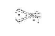
図1は、この発明の第1の実施の形態に係る生体組織縫合器を示すもので、縫合器本体2と分離配置される針受け部材であるアンビル12で構成される。(First embodiment)
FIG. 1 shows a biological tissue suturing device according to a first embodiment of the present invention, which is composed of an
即ち、縫合器本体2は、挿入部3の先端側に縫合部4が設けられ、この挿入部3の手元側に手元側操作部5が設けられる。この挿入部3には、その略中心部に内視鏡挿通管路6が縫合部4から手元側操作部5に至って形成され(図2参照)、この内視鏡挿通管路6には、内視鏡7が内挿される。この内視鏡7の処置具挿通管路8には、処置具、例えばアンビル把持具11が内挿され、このアンビル把持具11の先端のアンビル把持部9で上記アンビル12を開放自在に把持固定する。このアンビル把持具11には、手元側の手元側操作部10が配され、この手元側操作部10は、挿入部3の手元側に操作可能に配設される。 That is, the suturing device main body 2 is provided with a
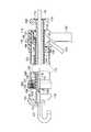
上記縫合部4には、略中空状のステープル収容体41が内挿され、このステープル収容体41の先端面には、複数のステープル収容孔20が、略環状に2重に設けられる(図2参照)。これらステープル収容孔20には、それぞれ略コの字型の縫合針部材であるステープル21が装着される。ここで、複数のステープル収容孔20は、2重に配列した環状の内周側と外周側とで互い違いになるように配設される。 A substantially hollow
また、ステープル収容体41には、そのステープル収容孔20の内周側に環状のカッター部材挿通孔22がステープル収容孔20に並設して設けられる。さらに、ステープル収容体41には、略円筒状の移動部材23が内視鏡挿通管路6を軸にしてその長軸方向に移動自在に内挿される。この移動部材23の手元側の一端には、雌螺子状に形成した螺子部24が設けられ、この螺子部24には、スクリュー部材27が螺合される。このスクリュー部材27は、ケーブル28を介して後述するモータユニット15(図1参照)に連結され、このモータユニット15が駆動されると、その回転力がケーブル28を介して伝達されて移動部材23に対する螺合が調整され、移動部材23を軸方向に移動させる。 Further, the staple accommodating
上記移動部材23の他端には、上記ステープル収容孔20の各々の相対する位置に該ステープル収容孔20に挿通可能な幅と厚みを持った略板状の複数のステープル押出し部材25が設けられ、移動部材23を手元側へ最大に後退させたとき、ステープル押出し部材25の先端がステープル収容孔20の手元側端に位置される。そして、移動部材23は、先端側へ最大に前進された状態で、ステープル押出し部材25を同方向に移動付勢してステープル21に当接させて、該ステープル21をステープル収容孔20の先端面から押出す如く作用する。 At the other end of the moving
また、ステープル押出し部材25の内周側には、円筒状のカッター部材26が内視鏡挿通管路6を全周的に囲む形に設けられる。このカッター部材26の刃先は、移動部材23を手元側へ最も後退させた状態で、縫合部4のステープル収容体41内に位置され、移動部材23が先端側に最も押出された状態で、縫合部4の端面より突出される。 In addition, a
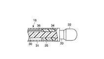
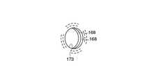
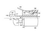
上記アンビル12は、アンビル本体42と軸部材16とを有し、軸部材16が内視鏡挿通管路6に挿通可能な外径形状に形成される。この軸部材16は、アンビル本体42より、軸30が延設され(図3参照)、この軸30の先端側には、略球状の先端把持部32が形成される。そして、この先端把持部32の基端側(後端側)に嵌合溝33が軸16の全周にわたって形成され、この嵌合溝33には、上記アンビル把持部9が選択的に嵌合把持される。 The
また、軸30には、軸カバー部材31が嵌合溝33の後部からアンビル本体42に至る領域を覆うように被着される。この軸カバー部材31には、透明部35が、嵌合部近傍に設けられ、この透明部35内の軸30には、位置情報発信手段である位置情報発信部材、例えばLED等の発光部材34が配設される。この発光部材34は、上記アンビル本体42内に設けられる図示しない電源部材にケーブル36を介して電気的に接続され、該電源部材(図示せず)を介して発光される。 A
他方のアンビル本体42は、2重状に略環状に配したステープル足折曲げ用の複数の凹部17が上記縫合部4のステープル収容孔20に相対する位置に設けられると共に、略環状のカッター部材収容スリット18が、上記縫合部4のカッター部材26に相対する位置に設けられる。また、アンビル本体42には、切除組織収容用の組織収容部19が上記軸部材16の基端を囲むようにう形に設けられると共に、その先端側から組織収容部19に貫通されるガイドワイヤ挿通孔39aが設けられる(図2参照)。 The other anvil
また、手元側操作部5には、折止部材13を介してケーブルチューブ14が延出され、このケーブルチューブ14の端部には、上記モーターユニット15が電気的に接続される。このモーターユニット15内には、図示しないモーターが内挿され、このモーター(図示せず)の回転力が上記ケーブル28に伝達される。このケーブル28は、ケーブルチューブ14から縫合部4までを連通するケーブル管路29内に配設されて上記スクリュー部材27に回転力伝達可能に連結される。 Further, a
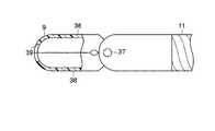
上記アンビル把持具11には、その先端にアンビル把持部9が把持開放自在に設けられる。このアンビル把持部9には、図4に示すように略中空状の一対の把持腕38が上記挿入部3の先端に設けられた軸37を中心に回動式に開閉自在に設けられ、この把持腕38の先端部には、閉じた状態で開口する把持溝39が設けられる。この把持溝39は、把持腕38が閉じられると、上記アンビル12の軸30の嵌合溝33に嵌合される。このアンビル把持部9の一対の把持腕38は、図示しないリンク機構及び操作ワイヤーを介して上記挿入部3の手元側に配した手元側操作部10に連結され、この手元側操作部10の開閉操作により、上記操作ワイヤー(図示せず)及び上記リンク機構(図示せず)を介して開閉操作される。 The
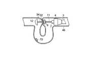
上記構成において、生体組織、例えば大腸を部分切除して縫合する場合には、先ず、図5に示すようにガイドワイヤ45を経肛門的に大腸46の深部まで挿入して、このガイドワイヤ45の肛門側端から、ガイドワイヤ挿通孔39aに通したアンビル12を該ガイドワイヤ45を案内にして大腸46の病変73を越える位置まで挿入する。次に、内視鏡挿通管路に位置検出装置である位置情報検出手段を構成する内視鏡を内挿した縫合器本体の挿入部を、経肛門的に大腸46に挿入し、その内視鏡7を病変73の肛門側手前まで挿入する。 In the above configuration, when a living tissue, for example, the large intestine is partially excised and sutured, first, a
ここで、経腹壁的に挿入した硬性鏡47で上記アンビル12と縫合器本体2の挿入部3を確認する。この際、アンビル12は、その軸30内の発光部材34(図3参照)が発光されると共に、挿入部3に内挿される内視鏡7が発光されていることにより、これら光を位置情報として、大腸46の腸管壁を通して各位置が確認される。そして、経腹壁的に腹腔内へ挿入した誘導部材である誘導手段を構成する把持鉗子74で大腸46の病変部73の近傍を把持して片側に寄せながら、もう一方の把持鉗子48でアンビル12を挿入部3の縫合部4の近傍に引寄せる。 Here, the
例えば大腸46は、略ループを描くようにしながらその側面と側面が寄ると共に、アンビル12と挿入部3の縫合部4とが近接する。アンビル12と縫合部4が近接した状態で、硬性鏡47の射出光量を下げて、内視鏡7で、アンビル12の発光部材34からの発光を経腸壁的に検出する。この光をガイドにアンビル把持具11で腸管壁ごと軸30を把持すると、アンビル12の先端把持部32が把持腕38の中空部に収容されて、該把持腕38の把持溝39と嵌合溝33とが嵌合され、アンビル把持具11で先端把持部32がしっかりと把持固定される(図6及び図7参照)。 For example, while the
次に、大腸46とともにアンビル12を把持した状態で、内視鏡7及びアンビル把持具11を、内視鏡挿通管路6へ引き込み、アンビル12と挿入部3の縫合部4とが2層に重なった大腸壁を間に挟んで当接される。ここで、モーターユニット15を駆動してケーブル28を回転させる。すると、ケーブル28の回転力がスクリュー部材27に伝達されて該スクリュー部材27が回転駆動され、それに伴って移動部材23が先端側方向に直線状に移動される。 Next, in a state where the
ここで、移動部材23は、その先端方向への移動に伴ってステープル押出し部材25を同方向に移動付勢してステープル収容孔20からステープル21を押出し、該ステープル21の先端部を2層に重ねられた大腸壁を穿通させてアンビル本体42の凹部17に圧接し、該凹部17の形状に沿ってその足を内側へ折り曲げて大腸壁を縫合する。そして、このステープル押出し部材25に引き続いてカッター部材26が、移動部材23により、縫合部4より突出されて、大腸壁を切除し吻合開口部49を形成して、その刃先がカッター部材収容スリット18内へ収容される。この際、カッター部材26により切除された生体組織は、組織収容部19へ収容される。 Here, the moving
このように大腸壁の縫合と切除が完了した段階で、一旦、アンビル把持具11を前進させてアンビル12と縫合部4との間に間隙を形成して、ステープル21で縫合された大腸46をリリースし、その後、挿入部を経口的に抜去する(図8参照)。 When the large intestine wall is thus sewn and excised, the
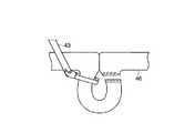
略ループを形成した大腸46は、ループ部内に病変73を内包する形で腸管側面同士が吻合している。このループ部を経腹壁的に腹腔内へ挿入した組織縫合切除器43でループ端部をそれぞれ縫合切離する(図9参照)。 The
なお、上記説明では、大腸部分の切除を行う手順について説明したが、これに限ることなく、その他の生体組織の縫合処置においても、同様に針受け部材であるアンビル12に位置情報発信手段である発光部材34を配し、このアンビル12を第1の生体組織内に挿入し、複数の針射出部が略環状に設けられた上記アンビル12と縫合可能に合体される縫合部4を有し、アンビル把持具11の装着される内視鏡7が挿通される挿入部3を第2の生体組織内に挿入する。 In the above description, the procedure for excising the large intestine portion has been described. However, the present invention is not limited to this, and the position information transmitting means is similarly provided to the
次に、上記アンビル12の発光部材34からの位置情報を、例えば挿入部3に挿通した内視鏡7又は該内視鏡7に装着されるアンビル把持具11、あるいは経腹壁的に挿入した硬性鏡47の少なくとも一方で検出してアンビル12の位置を特定し、誘導手段として上記アンビル把持具11あるいは経腹壁的に挿入した把持具、例えば把持鉗子48で誘導して第1及び第2の生体組織を介してアンビル12をアンビル把持具12で把持固定し、その後、挿入部3の縫合部4とアンビル12により縫合処置が施される。 Next, the position information from the
なお、上記縫合処置手順では、アンビル12からの位置情報を検出する位置情報検出手段及び検出情報に基づいてアンビル12を誘導する誘導手段として、経腹壁的に挿入した硬性鏡47及び把持鉗子48を使用した場合で説明したが、これに限るものでなく、挿入部3の装着した内視鏡7及びアンビル把持具11を用いて構成しても良い。 In the suturing procedure, the
このように、上記生体組織縫合器は、アンビル12に発光部材34を配し、この発光部材34からの位置情報に基づいてアンビル12の位置を特定して挿入部3に挿通した内視鏡7のアンビル把持具11でアンビル12を、縫合部4に対向して把持固定するように構成した。 As described above, the biological tissue suturing device includes the
これによれば、アンビル12の位置情報を経腹壁的に挿入した硬性鏡47で検出し、同様に経腹壁的に挿入した把持鉗子48を用いて高精度な誘導を行うことが可能となり、確実な把持固定を迅速ににして容易に行うことができて、縫合処置の迅速化を図ることができる。 According to this, it is possible to detect the position information of the
例えば把持鉗子48の補助下で、生体組織、例えば大腸等の生体管路内に位置するアンビル12と、挿入部3の縫合部4とを近接させることで、経管壁的に内視鏡で、アンビル12を確認・把持して大腸の吻合を容易に行うことが可能となる。 For example, with the assistance of the grasping
また、これによれば、腸管を切開くことなく大腸等の生体管路部分の切除および吻合が可能となり、信頼性の高い高精度な切除・吻合処理を確実に行うことが可能となる。 Further, according to this, it is possible to excise and anastomoses the body duct such as the large intestine without incising the intestinal tract, and it is possible to reliably perform highly reliable excision / anastomosis processing with high reliability.
なお、上記内視鏡7に装着されるアンビル把持具11のアンビル把持部構造としては、上記説明の構成に限ることなく、その他、図10、図11及び図12、図13及び図14に示すように構成しても同様に有効である。但し、図10乃至図14においては、上記図1乃至図9と同一部分について、同一符号を付して、その説明を省略する。 Note that the anvil gripping portion structure of the
図10のアンビル把持部構造は、アンビル把持部50として、上記手元側操作部10に接続される操作ワイヤ51をシース52の先端部に内挿し、この操作ワイヤ51の先端に、一対の把持腕54を開閉自在に配して構成する。この一対の把持腕54は、シース52の先端部から突出した状態では拡開可能に配され、その先端側に上記アンビル12の軸30の嵌合溝33に嵌合することができる開口部径を有した把持溝53と、アンビル12の先端把持部32を収容する中空部55が設けられる。 The anvil gripping portion structure of FIG. 10 has an
また、図11及び図12のアンビル把持部構造は、アンビル56の軸部材57の先端側に嵌合溝58及び先端把持部59が順に設けられ、先端把持部59の先端側に位置情報発信手段を兼用する磁石部材60が設けられる。そして、アンビル56と組合せて使用するアンビル把持部61は、その先端部に凹部62が上記軸部材57の嵌合溝58に対応して設けられる。そして、凹部62には、上記磁石部材60と協働して位置情報発信手段を兼用する磁石部材63が軸方向に移動自在に収容され、この磁石部材63には、上記手元側操作部10の操作により突没自在な操作ワイヤ64が接続される。 11 and 12 has a
上記構成において、例えば小腸等の生体管路内にアンビル56を挿入し、このアンビル56にアンビル把持具61を近接させると共に、上記手元側操作部10を操作して操作ワイヤ64を押出し、磁石部材63をアンビル把持部61より突出させる。すると、磁石部材63は、アンビル56の磁石部材60と相互の磁力により互いに引き合って接近されて磁気結合される。ここで、再び上記手元側操作部10を操作して操作ワイヤ64を引き込み操作することにより、軸部材57は、アンビル把持部61の内腔へ引き込まれて、その嵌合溝58に対して凸部62が嵌合かれて把持固定される(図12参照)。この相互の磁石部材60と磁石部材63の磁力の作用により、さらに把持固定操作の確実化の促進を図ることが可能となる。 In the above-described configuration, for example, the
図13及び図14のアンビル把持部構造は、アンビル把持部65として、上記手元側操作部10に接続される操作ワイヤ68を操作チューブ67に内挿し、この操作チューブ67を挿入シース66内に軸方向に移動自在に内挿する。そして、操作チューブ67の先端には、一対の把持腕71が挿入シース66より突出した状態では拡開状態となるように開閉自在に設けられる。この一対の把持腕71には、その先端側に上記軸部材57の嵌合溝58(図11参照)に嵌合する開口径を有した把持溝69と、先端把持部59を収容する中空部70が設けられる。 In the anvil gripping portion structure of FIGS. 13 and 14, as the
また、上記操作ワイヤ68の先端には、磁石部材72が、上記アンビル56の軸部材57の軸部材60に対応して設けられ、上記操作チューブ67とともに挿入シース66内を軸方向に移動されて該挿入シース66の先端より出入りされる。 A
上記構成において、先ず,手元側操作部10を操作して操作チューブ67及び操作ワイヤ68を押し出し操作した状態で、アンビル保持部65を、例えば小腸等の生体管路内を挿入したアンビル56に近接させる。すると、アンビル56の磁石部材60と操作ワイヤの磁石部材72とが引き合って接近されて磁気結合される。 In the above-described configuration, first, in the state where the
続いて、操作ワイヤ68を操作チューブ67内へ引き込むと共に、操作チューブ67を挿入シース66内へ引き込に操作する。すると、操作チューブ67の一対の把持腕71が閉じて、その把持溝69がアンビル56の軸部材57の嵌合溝58に嵌合され、アンビル56がアンビル把持部65に把持固定される。 Subsequently, the
なお、上記実施の形態の説明では、位置情報発信部材である位置情報発信手段として、LED等の発光部材34や磁石部材60,63による磁力を利用するように構成した場合で説明したが、これに限ることなく、可視光等の電磁波を位置情報として発信させるように構成してもよい。この位置情報発信手段と、その位置情報を検出する位置検出手段としては、例えばLED等の半導体や有機EL等の電気エネルギーを可視光等の光エネルギーへ変換する手段や、半導体レーザーによるレーザー光、ルミノールを用いた化学反応による発光手段であっても、それ自体が発光せずとも内視鏡からの射出光により蛍光を発する蛍光物質であってもよい。この場合、特に緑色や青色の発 光は、腹腔内での検出が容易となることで、有効な効果が期待される。 In the description of the above embodiment, the position information transmitting means, which is a position information transmitting member, has been described in the case where the magnetic force generated by the
また、発光する光エネルギーにおいても、可視光に限るものでなく、例えばラジオ波やX線、ガンマ線等の極短波長のものや、赤外線等の波長の長いものでよい。また、発信するエネルギとしては、その他、超音波等の振動エネルギーや音響エネルギーを用いることも有効である。これらの位置情報を検出する手段としては、内視鏡先端に設けたCCD等による光の検出以外に、アンテナによるラジオ波の検出、ホール素子等による磁場の検出、シンチレータによる放射線検出、トランスデューサによる超音波の検出等の方法を取ることが可能である。 Also, the light energy emitted is not limited to visible light, and may be one having an extremely short wavelength such as a radio wave, X-ray or gamma ray, or one having a long wavelength such as infrared. In addition, it is also effective to use vibration energy such as ultrasonic waves or acoustic energy as transmitted energy. As means for detecting such position information, in addition to detection of light by a CCD or the like provided at the distal end of the endoscope, detection of radio waves by an antenna, detection of a magnetic field by a Hall element, detection of radiation by a scintillator, detection by a transducer, It is possible to take a method such as detection of sound waves.
さらに、上記第1の実施の形態では、処置具であるアンビル把持具11を、挿入部3に内視鏡7を介して内挿するように構成した場合で説明したが、これに限ることなく、アンビル把持具11を、例えば挿入部3の内視鏡挿通管路6に直接的に内挿するように構成することも可能である。 Further, in the first embodiment, the
(第2の実施の形態)
図15及び図16は、この発明の第2の実施の形態に係る生体組織縫合器の要部を示すもので、図15は把持状態を示し、図16は、縫合状態を示す。但し、図15及び図16においては、上記第1の実施の形態と同一部分について、同一符号を付して、その詳細な説明を省略する。(Second Embodiment)
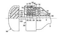
15 and 16 show the main part of the biological tissue suturing device according to the second embodiment of the present invention. FIG. 15 shows a grasping state, and FIG. 16 shows a suturing state. 15 and FIG. 16, the same parts as those in the first embodiment are denoted by the same reference numerals, and detailed description thereof is omitted.
即ち、縫合部76は、上記挿入部3の先端部に設けられ、略環状のステープル収容体77が内挿される。このステープル収容体77には、その先端面に環状に2重に配設される複数のステープル収容孔78が貫通して設けられる。これらステープル収容孔78は、外側と内側とでは、その孔の位置がそれぞれ互い違いになるように設けられ、そのステープル収容体78の手元側端には、図17及び図18に示すようにステープルスライドスリット79がステープル収容孔78をなぞる形に環状に設けられる。 That is, the
これらステープル収容孔78には、それぞれ縫合針部材である略コの字型のステープル80が収容され、そのステープル80の手元側にステープル押出し部材84が対向配置される。このステープル押出し部材84は、ステープル80に当接され、ステープル収容孔78の手元側に設けられた突起部81に当接する突起部82及び突起部81より手元側においてステープルスライドスリット79内に突出する突出部83が設けられる。このステープル押出し部材84の突出部83は、ステープルスライドスリット79の接線方向に沿って斜めにカットした傾斜面を有する。 In these staple accommodation holes 78, substantially
また、ステープル収容体77には、略環状のカッター部材挿通孔85が上記ステープル収容孔78の内周側に設けられる。そして、ステープル収容体77の手元側には、先端側が平面である略筒状の回転部材86が、上記内視鏡挿通管路6を軸にして回動自在に配設される。この回転部材86の先端面には、略板状のステープルスライダ87が設けられる。このステープルスライダ87は、その先端部が斜めにカットされた傾斜面を有し、この傾斜面が、上記突出部83の斜めにカットされた傾斜面に当接される(図17参照)。そして、ステープルスライダ87の内周側には、略薄板状のカッター部材88が設けられる。このカッター部材88は、その刃先が上記カッター部材挿通孔85を挿通してステープル収容体77より先端側へ突出される。 The
上記回転部材86の手元側は、略円筒状の形成され、その内壁側に図示しない歯車が設けられ、この歯車(図示せず)に歯車部材89が噛合される。この歯車部材89は、駆動歯車90が噛合される。この駆動歯車は、ケーブル91を介して上記モーターユニット15に接続され、このモーターユニット5の駆動力がケーブル91を介して伝達されて回転駆動される。 The proximal side of the rotating
ステープル収容体77の先端側には、カバー部材92が被着される。このカバー部材92には、略環状に2重に複数のステープル挿通孔93がステープル収容孔78に相対する位置に設けられ、このステープル挿通孔93の内周部に中心孔94が上記カッター挿通孔85に対応して設けられる。そして、このカバー部材92とステープル収容体77との間には、バネ部材95がステープル収容体77に対してカバー部材92を先端側へ押出すように係着される。このカバー部材92は、その手元側内壁側に設けられた突起97がステープル収容体77の突起部材96に当接されていることで、ステープル収容体77より脱落することがない。 A
また、アンビル98には、上記内視鏡挿通管路6内を挿通したアンビル把持具99に把持固定される軸部材100が略中央部に突設される。そして、この軸部材100の周囲部には、略環状に2重に複数の凹部101が上記ステープル収容孔78及びステープル挿通孔93に相対する位置に設けられると共に、カッター収容スリット102が上記カッター挿通孔85に相対する位置に設けられる。 Further, the
なお、アンビル98には、図15及び図16において図示していないが上記第1の実施の形態と同様に位置情報発信手段として、例えば上記発光部材34が、例えば軸部材100に対応して設けられ、この発光部材34を介して位置情報を発信する。 Although not shown in FIGS. 15 and 16, the
上記構成において、生体管路壁、例えば胃壁103および小腸壁104を縫合する場合には、先ず、アンビル98からの位置情報に基づいて、挿入部3に挿通した内視鏡7に組み込んだアンビル把持具99を操作して、アンビル98の軸部材100を把持して縫合部76とアンビル98との間に、縫合部76とアンビル98との間に胃壁103および小腸壁104位置させる。この状態で、アンビル把持具99を内視鏡挿通管路6内に引き込むと、カバー部材92がバネ部材95の付勢力に抗して手元側に押込まれる。これにより、カッター部材88は、その刃先がカッター部材挿通孔85及び中心孔94を挿通してカバー部材92の先端面より突出し、胃壁103及び小腸壁104を穿通しながらカッター収容スリット102の中へ収容され、縫合部75、胃壁103、小腸壁104及びアンビル98とが密着した状態となる(図16、図18参照)。 In the above configuration, when the biological duct wall, for example, the
ここで、上記挿入部3のモーターユニット15を駆動操作して駆動させる。すると、このモータユニット15の駆動力がケーブル91に伝達されて回転され、駆動歯車90、歯車89を介して回転部材86が回転駆動される。回転部材86は、その回転によりステープルスライダ87をステープルスライドスリット79内を突出部83の斜めにカットした傾斜面に当接しながら移動させ、ステープル押出し部材84及びステープル80を先端側へ押出す。すると、ステープル80は、その足部がステープル挿通孔93を挿通して胃壁103および小腸壁104を穿通し、相対する位置にあるアンビル98の凹部101に当接して、該凹部101に沿って足部が内側へ折り曲げられて胃壁103及び小腸壁104を縫合する。 Here, the
同時に、ステープルスライダ87は、回転部材86の回転に伴ってカッター部材88をカッター挿通孔85に沿って回転させて胃壁103及び小腸壁104を穿通した刃先部で、該胃壁103及び小腸壁104を環状に切除する。 At the same time, the
この第2の実施の形態によれば、略板状のカッター部材88を用いて生体組織を環状に切除することが可能となることにより、ステープル押出し部材84やカッター部材88等の構成部品や生体組織に掛かる力を軽減することができる。従って、生体組織に掛かる力量軽減による生体組織の挫滅等の損傷防止や、駆動力軽減に伴う駆動用ケーブル91の細径化や構成の簡略化を図ることが可能となる。 According to the second embodiment, it is possible to cut the living tissue in an annular shape by using the substantially plate-shaped
(第3の実施の形態)
図19は、この発明の第3の実施の形態に係る生体組織縫合器の要部を取り出して示したものである。但し、図19においては、上記第1の実施の形態と同一部分について、同一符号を付して、その詳細な説明を省略する。(Third embodiment)
FIG. 19 shows an essential part of a biological tissue suturing device according to a third embodiment of the present invention. However, in FIG. 19, the same parts as those in the first embodiment are denoted by the same reference numerals, and detailed description thereof is omitted.
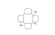
即ち、アンビル150は、アンビル本体152の一端面に球面を有したアンビル先端部151が形成され(図19及び図20参照)、このアンビル本体152の他方面である手前側には、その略中心部に先端把持部159を有した軸部材158が突出して設けられる。また、アンビル本体152には、その周囲部に凹状のアンビル腕収容部153が、複数箇所、例えば略十字状に4箇所設けられ、このアンビル腕収容部153には、針受けを構成するアンビル腕155が回動軸154を介して折畳み展開自在に設けられる。 That is, the
これらアンビル腕155には、その回動軸154と突起部156間に巻きバネ部材157が展開方向に付勢力を付与するようにそれぞれ係着され、この巻きバネ部材157の付勢力により回動軸回りに展開されると、アンビル本体152より周方向に突出される。そして、これらアンビル腕155は、巻きバネ部材157の付勢力に抗して反転されてアンビル腕収容部153に折畳み収容される。これにより、アンビル150は、外形形状がアンビル本体152の外形寸法と略同様となり、所謂、小径化される。 A winding
上記アンビル腕155には、その手元側に凹状の係止部163がそれぞれ設けられ、この各係止部163には、操作ワイヤ165の一端に放射状に形成された突起部164が選択的に係止される。この操作ワイヤ165は、その中間部が上記軸部材158に設けられるワイヤ挿通管路161に軸方向に移動自在に遊挿される。この操作ワイヤ165の基端部には、操作部162が設けられ、この操作部162は、軸部材158に設けられるスリット160に軸方向に移動操作可能に突設される。この操作ワイヤ165は、バネ部材166を介してアンビル本体方向に付勢力が付与され、その操作部162がアンビル把持具170に把持されると、このバネ部材166の付勢力に抗して手元側方向に移動されて、その複数の突起部164がアンビル腕155の係止部163からそれぞれ離脱される。 Each of the
また、上記アンビル150には、図中において図示していないが上記第1の実施の形態と同様に位置情報発信手段として、例えば上記発光部材34が、例えば軸部材158に対応して設けられ、この発光部材34を介して位置情報を発信する。 The
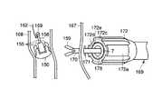
一方、生体組織縫合器を構成する挿入部169の先端側には、縫合部172が設けられる。この縫合部172には、例えば幅広部172aがアンビル150のアンビル腕155に対応して略十字状に4箇所設けられる。この幅広部172aは、アンビル腕155の展開状態に対応して形状が設定され、例えば上述した第1の実施の形態と同様にステープル収容孔20及びカッター部材挿通孔22が設けられる。また、この縫合部172には、同様にアンビル把持具170の挿着される上記内視鏡7が挿通される内視鏡挿通管路178が設けられる。 On the other hand, a
上記構成において、アンビル150は、そのアンビル腕155が回動軸回りに折畳まれてアンビル腕収容部153に収容された状態で、例えば経口的に生体管路である小腸168へ挿入される。他方、挿入部169は、例えば経口的に生体管路である胃167に挿入され、例えば胃167の一部を切開し、その開口部171から腹腔内へアプローチする(図21参照)。この際、小腸168のアンビル150からの位置情報に基づいてアンビル159を確認して、小腸168の一部を切開してアンビル軸部材158を、挿入部のアンビル把持具170で先端把持部159及び操作ワイヤ165の操作部162を併せて把持・固定する(図22参照)。 In the above configuration, the
次に、アンビル把持具170を挿入部内に引き込み操作する。すると、アンビル把持具170により操作ワイヤ165の操作部162がバネ部材166の付勢力に抗して手元側に移動され、その突起部164がアンビル腕155の係止部163から離脱される。これにより、アンビル腕155は、巻きバネ部材157の付勢力により回動軸回りに展開方向に回動されてアンビル腕収容部153から離脱されて展開される。同時に、アンビル把持具170が挿入部169内に引き込まれると、アンビル150は、そのアンビル腕155が縫合部172の幅広部172aに対して胃壁および小腸壁を間に挟んで当接される。 Next, the
ここで、挿入部169の操作部10(図1参照)を操作して、縫合部172のステープル挿通孔172cからステープル(図23では、図の都合上、図示せず)を押し出し操作する。すると、押し出されたステープル21は、その先端部が胃壁と小腸壁に穿通されてアンビル腕155の図示しない凹部に押し付けられて折曲げられて縫合される(図23参照)。その後、縫合部172のカッター部材挿通孔172dよりカッター部材172eが押し出されて縫合した内周側が環状に切除されて、図24に示すように吻合孔173が形成される。 Here, the operation unit 10 (see FIG. 1) of the
この第3の実施の形態によれば、アンビル150の生体管路への容易な挿入を実現したうえで、大口径な縫合を確保することができることにより、さらに、取扱い操作性の向上が図れる。 According to the third embodiment, since easy insertion of the
また、この第3の実施の形態によれば、縫合時における縫合部172とアンビル1509との位置関係が厳密に設定することが可能となる。そして、これによれば、縫合部172とアンビル150との位置関係の調整は、内視鏡7およびアンビル把持具170の捻り操作等により行なうことができることにより、簡便にして容易に正確な把持固定が可能となる。 Further, according to the third embodiment, the positional relationship between the stitched
また、アンビル構造としては、上記構成に限ることなく、その他、図25に示すように構成することも可能である。但し、図25においては、上記図19乃至図24と同一部分について同一符号を付して、その詳細な説明を省略する。 In addition, the anvil structure is not limited to the above-described configuration, but may be configured as shown in FIG. However, in FIG. 25, the same parts as those in FIGS. 19 to 24 are denoted by the same reference numerals, and detailed description thereof is omitted.
即ち、図25においては、上記アンビル本体151の軸部材158の根元側に、例えば略6角形形状の凸状嵌合部158aを設ける。そして、挿入部169の縫合部172には、内視鏡挿通管路178の先端側に略6角形形状の凹状嵌合部172bを形成し、この凹状嵌合部172bに対してアンビル本体151の凸状嵌合部158aを嵌合させた状態で把持固定するように構成したものである。これにより、アンビル150と縫合部172との位置関係が、正確に位置決め固定され、さらに良好な効果が期待される。 That is, in FIG. 25, a substantially hexagonal convex fitting portion 158a is provided on the base side of the
次に、生体組織縫合器の参考例について、図面を参照して説明する。 Next, a reference example of a biological tissue suture device will be described with reference to the drawings.
図26は、第1の参考例に係る生体組織縫合器を示すもので、略軟性な生体組織内へ挿入する挿入部112と、挿入部先端側に設けられた縫合部111と、挿入部手元側に設けられた操作部113と、縫合部111より先端側に配設されるアンビル部114とで構成される。 FIG. 26 shows a biological tissue suturing device according to a first reference example. The
このうちアンビル部114の手元側には、操作軸115が延設される。この操作軸115は、縫合部111、挿入部112及び操作部113を先端から手元側までを連通する操作軸挿通管路116に進退自在に配設され、その手元側が操作部113から突出されて、その手元側端部に把持部119が設けられる。 Among these, the operating shaft 115 is extended on the hand side of the
また、アンビル部114には、その先端側に開口されて手元側まで連通されて上記操作軸115に連通される内視鏡挿通管路121が設けられ、この内視鏡挿通管路121には、内視鏡131が操作自在に挿通される。この内視鏡挿通管路121には、その先端側と手元側に気密弁117,118が所定の間隔を有して設けられる。また、操作軸115には、先端側へ押出された状態で、アンビル部114と縫合部111との間に位置する側壁部位に複数の吸引孔120が設けられると共に、その手元側端部に上記内視鏡挿通管路121と連通される吸引口金122が設けられる。この吸引口金122には、図示しない吸引源が接続され、該吸引源(図示せず)を介して操作軸内を吸引する。 Further, the
上記縫合部111は、先端側が略円筒状に形成され、その手元側に操作軸挿通管路116が設けられる、そして、この操作軸挿通管路116には、上記操作軸115が挿入される。 The
また、縫合部111には、チューブ体を有したステープル収容体123が手元側操作部113まで延設される内蔵される。このステープル収容体123の先端側には、略環状に2重に複数個のステープル収容孔124がステープル収容体123を貫通するよう設けられ、このステープル収容孔124には、ステープル125がそれぞれ収容される。 In addition, the
ステープル収容体123の手元側には、操作軸挿通管路116と同軸に前後動自在に設けられた略円筒状の移動部材126が設けられ、この移動部材126の先端面には、上記ステープル収容孔124に相対する位置に略薄板上のステープル押出し部材127が複数配設される。そして、移動部材126の手元側壁面には、挿入部112の先端から手元側に連通する押出し部材129が手元側操作部113まで延設される。この押出し部材129は、上記操作軸115に外装される押出し部材挿通管路128に移動自在に配設される。 A substantially cylindrical moving
また、上記アンビル部114の手元側端面には、凹部130が上記ステープル収容孔124に相対する位置に設けられる。 Further, a
上記操作部113には、把持用の握り部材132が突出して設けられ、この握り部材132の略根元の部位には、ハンドル部材134が軸133を中心に回動操作自在に設けられる。このハンドル部材134は、操作リング144とリンク135を介してリンク結合される。操作リング144は、上記操作軸挿通管路116と同軸に前後動自在に配設され、上記押出し部材129に取付けられる。 A
また、操作部113の内部には、手元側より内側に突出される略棒状の突起部137が設けられる。この突起部137は、上記操作軸115の側部に設けられた弾性変形自在な片梁バネ部材136に対向配置され、該片梁バネ部材136に選択的に弾性係止される。さらに、操作軸115の突起部137と上記ステープル収容体123との間には、バネ部材138が係着される。 In addition, a substantially rod-shaped
また、操作部113には、スイッチ孔139が片梁バネ部材136に対向して設けられ、このスイッチ孔139には、スイッチ140が押圧操作自在に設けられる。このスイッチ40は、操作軸115の片梁バネ部材136に対向され、その押圧操作により、該片梁バネ部材136を押圧して、操作部113の突起部137との係止を解除する。これにより、操作軸115は、上記バネ部材138の付勢力により手元側に移動付勢される。 In addition, a switch hole 139 is provided in the operation portion 113 so as to face the single
上記構成において、例えば噴門部における組織縫合である胃−食道接合部143に弁構造を形成したりする、所謂、逆流性食道炎の治療等に供される。 In the above configuration, for example, a valve structure is formed in the stomach-esophageal joint 143 that is tissue suture in the cardia, and so-called reflux esophagitis is treated.
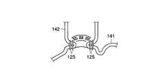
即ち、アンビル部114を含む挿入部112の縫合部111を、操作軸115内に挿通した内視鏡131の視野下において経口的に胃−食道接合部143まで挿入する。次に、操作部113より突出される操作軸115をバネ部材138の圧縮応力に抗して押出し操作する。すると、アンビル部114は、縫合部111より先端側へ突出され、アンビル部114と縫合部111の先端面との間に図26中断面で示すように空間を形成する。ここで、片梁バネ部材136は、操作軸115の突起部137が当接されて保持され、その先端部でスイッチ140を操作部113の外に押し上げる。この際、胃141内へ挿入した内視鏡131を反転してアンビル部114の位置を調整して、該空間が胃−食道接合部143の適切な位置に来るように調整する。 That is, the
ここで、操作軸115の把持部119に設けた吸引口金122に接続した上記吸引源(図示せず)を駆動する。すると、操作軸115内が吸引され、アンビル部114と縫合部111との間に形成した空間内に食道142が吸引される如く引き付けられる(図27参照)。続いて、操作部のスイッチ140を押圧操作する。すると、操作軸115は、バネ部材138の付勢力により手元側方向に押戻される如く移動され、アンビル部114と縫合部111との間に食道142が挟み込まれる。 Here, the suction source (not shown) connected to the
次に、ハンドル134を握り込むと、リンク135を介して操作リング144が先端側側方向に移動され、それに伴い押出し部材129と移動部材126及びステープル押出し部材127が先端側方向に移動される。ここで、ステープル押出し部材127は、ステープル125をステープル収容孔127から突出させ、このステープル125の先端部が食道142を穿通されて、アンビル部114の凹部130に当接され、その先端が内側へ折り曲げて、食道を全周的に縫合する(図28参照)。 Next, when the
この第1の参考例によれば、経口的なアプローチで、かつ一気的に食道−胃接合部を全周的に縫合することができることにより、胃−食道接合部に所望の弁を容易に形成することができるため、逆流性食道炎に対する高い治療効果が得られる。しかも、これによれば、内視鏡視野下で縫合する位置を確認しながら縫合を実施することで、簡便にして容易に確実な治療を実現することが可能となる。 According to the first reference example, a desired valve can be easily formed at the gastric-esophageal junction by being able to suture the entire esophagus-gastric junction at an all-or-two stroke by an oral approach. Therefore, a high therapeutic effect for reflux esophagitis can be obtained. Moreover, according to this, by performing the suturing while confirming the suturing position under the endoscope visual field, it is possible to easily and easily realize a reliable treatment.
また、図29は、第2の参考例に係る生体組織縫合器を示すもので、その先端側に設けられたアンビル部材176には、その手元側に操作軸部材177が突出されて設けられる。これらアンビル部材176及び操作軸部材177には、内視鏡挿通管路178が先端側から手元側に至って形成される。このうち操作軸部材177には、縫合器本体179が前後動自在に外装され、この縫合器本体179の外周部には、針押込み部材180が前後動自在に外装される。上記内視鏡挿通管路178には、内視鏡181が挿入され、その手元側に図示しない手元側操作部が設けられる。 FIG. 29 shows a biological tissue suturing device according to a second reference example. An
他方のアンビル部材176には、その外周壁に複数の長軸方向(前後方向)にスリット部182が所定の間隔を有して設けられる(図30参照)。また、上記縫合器本体179の先端側には、複数の係止針収容スリット部183が、上記スリット部182に対向して所定の間隔を有して設けられる。これら係止針収容スリット部183には、その手元側端部の固定位置185に係止針部材184の手前側の端部が固定されて収容される。 The
これら係止針部材184は、その手前側において、先端側が縫合器本体179の外側方向に開くように傾斜角を有して形成され、その針先端部が縫合器本体179の先端部よりされ、且つ、縫合器本体179の周壁よりも外側に開くように配される。そして、上記針押込み部材180の先端側には、スリット部182及び係止針収容スリット部183に前後動自在に収容される複数の抑え突起186が所定の間隔に設けられる。 These locking
また、上記縫合器本体179の先端部には、その係止針収容スリット183の間に複数のステープル収容孔187が、上記アンビル部材176の手前側面に形成される図示しない針折曲げ用凹部に対応して設けられる。 In addition, a plurality of staple accommodation holes 187 are formed at the distal end portion of the suturing device
上記構成において、先ず、操作軸部材177を引き込み操作してアンビル部材176を縫合器本体179に略当接させると共に、針押込み部材180を先端側方向に移動させる。すると、係止針部材184は、針押し込み部材180の抑え突起186により、押し込まれてアンビル部材176のスリット部182と係止針収容スリット部182内に収容される。 In the above-described configuration, first, the
この状態で、内視鏡挿通管路178に内視鏡181を挿通し、内視鏡181に沿って経口的に食道−胃縫合部189まで全体を挿入する。続いて、胃内において内視鏡181を反転視しつつ、操作軸部材177を突出させて、アンビル部材176と、縫合器本体179の先端部との間に図29中断面で示すように空間を形成する。ここで、針押込み部材180を手元側へ引き戻すと、係止針部材184が針押し込み部材180の外周側へ突出される。 In this state, the
この状態で、全体を経口的に押し進めて、係止針部材184を食道188の筋層まで穿刺し(図31参照)、続いて針押込み部材180を縫合器本体179に対して押し進める。すると、係止針部材184に対して針押込み部材180の抑え突起186が当接されて先端側へ移動されることで、係止針部材184が、再び係止針収容スリット部183内に収容される。これにより、食道188がアンビル部材176と縫合器本体179の先端との間に形成された空間内へ引寄せられる。この状態で操作軸部材177を引き込むことでアンビル部材176と縫合器本体179の先端で食道188を挟み込み、続いて図示しない操作部の操作により、縫合器本体179内に収容配置したステープル(図の都合上、図示せず)で食道組織を略全周的に縫合する。 In this state, the whole is pushed forward orally, and the locking
この第2の参考例によれば、係止針部材184で食道組織を機械的に引き下げるように構成しているため、筋層を含んだ全層で食道組織を全周的に縫合して、食道−胃接合部に弁構造を形成できることにより、形成した弁の長期使用に耐えることが可能となる。 According to the second reference example, since the esophageal tissue is mechanically pulled down by the locking
なお、上記参考例では、生体組織の縫合を全周的に行うように構成した場合で説明したが、これに限るものではなく、例えば縫合する位置を食道−胃接合部の1/3周や半周等一部に限定することも可能である。これにより、例えば症状の比較的軽微な患者において、全周的に弁構造を形成する必要なく、逆に縫合部を限定することで縫合部、アンビル及び食道組織引下げに用いられる係止針部材等の数や外径を少なくすることで、生体組織縫合器の挿入部外径を細径化し、生体組織縫合器の挿入時における患者への負担を軽くすることができる。 In the above-described reference example, the case where the tissue is configured to be sutured all around has been described. However, the present invention is not limited to this. For example, the stitching position is set to 1/3 of the esophagus-gastric junction, It is also possible to limit to a part such as a half circumference. Thus, for example, in patients with relatively mild symptoms, it is not necessary to form a valve structure all around, and conversely, by limiting the sutured portion, the suture needle member used for lowering the sutured portion, anvil and esophageal tissue, etc. By reducing the number and the outer diameter, the outer diameter of the insertion portion of the biological tissue suture device can be reduced, and the burden on the patient when inserting the biological tissue suture device can be reduced.
よって、この発明は、上記実施の形態に限ることなく、その他、実施段階ではその要旨を逸脱しない範囲で種々の変形を実施し得ることが可能である。さらに、上記実施の形態には、種々の段階の発明が含まれており、開示される複数の構成要件における適宜な組合せにより種々の発明が抽出され得る。 Therefore, the present invention is not limited to the above-described embodiment, and various modifications can be made without departing from the scope of the invention in the implementation stage. Further, the above embodiments include inventions at various stages, and various inventions can be extracted by appropriately combining a plurality of disclosed constituent elements.
例えば実施の形態に示される全構成要件から幾つかの構成要件が削除されても、発明が解決しようとする課題の欄で述べた課題が解決でき、発明の効果で述べられている効果が得られる場合には、この構成要件が削除された構成が発明として抽出され得る。 For example, even if some constituent requirements are deleted from all the constituent requirements shown in the embodiment, the problem described in the column of the problem to be solved by the invention can be solved, and the effect described in the effect of the invention can be obtained. In such a case, a configuration in which this configuration requirement is deleted can be extracted as an invention.
また、この発明は、上記各実施の形態によれば、その他、次のような構成を得ることもできる。 In addition, according to each of the above embodiments, the present invention can also obtain the following configuration.
(付記1)
内視鏡挿通管路が設けられた挿入部と、
前記挿入部の先端側に配される複数の針射出部が略環状に設けられた縫合部と、
前記挿入部と分離配置され、生体組織を介して前記縫合部と対向された状態で、前記挿入部を介して導入された処置具に把持固定されるものであって、前記縫合部の針射出部から打ち出された縫合針部材の前記生体組織を貫通した先端部を折曲げる針受け部材と、
前記針受け部材に設けられ、位置情報を発信する位置情報発信部材と、
を具備することを特徴とする生体組織縫合器。(Appendix 1)
An insertion portion provided with an endoscope insertion conduit;
A suture part in which a plurality of needle ejection parts arranged on the distal end side of the insertion part are provided in a substantially annular shape;
The needle is ejected from the suturing portion, arranged separately from the insertion portion, and held and fixed to the treatment instrument introduced via the insertion portion in a state of being opposed to the suturing portion via a living tissue. A needle receiving member that bends the distal end portion penetrating the living tissue of the suture needle member punched from the portion;
A position information transmitting member provided on the needle receiving member for transmitting position information;
A biological tissue suturing device comprising:
(付記2)
前記位置情報発信部材からの位置情報を受信して前記針受け部材の位置を検出する位置検出装置と、
前記位置検出装置の検出情報に基づいて前記針受け部材を誘導するための誘導部材と、
を更に備えることを特徴とする付記1記載の生体組織縫合器。(Appendix 2)
A position detecting device that receives position information from the position information transmitting member and detects the position of the needle receiving member;
A guiding member for guiding the needle receiving member based on detection information of the position detecting device;
The biological tissue suturing device according to appendix 1, further comprising:
(付記3)
前記位置検出装置は、前記挿入部を介して導入される内視鏡又は前記処置具の少なくとも一方に配され、前記誘導部材は、前記挿入部あるいは前記内視鏡を介して導入される前記処置具によって構成されることを特徴とする付記2記載の生体組織縫合器。(Appendix 3)
The position detection device is disposed in at least one of an endoscope or the treatment instrument introduced through the insertion portion, and the guide member is introduced through the insertion portion or the endoscope. The biological tissue suturing device according to appendix 2, characterized by comprising a tool.
(付記4)
前記位置検出装置及び前記誘導部材は、少なくとも一方が経腹壁的に導入される内視鏡及び処置具を含むことを特徴とする付記2の生体組織縫合器。(Appendix 4)
The biological tissue suturing device according to appendix 2, wherein the position detection device and the guide member include an endoscope and a treatment tool, at least one of which is introduced transperitoneally.
(付記5)
前記針受け部材は、前記処置部に対して磁気力により合体されて把持固定されることを特徴とする付記項1乃至4のいずれか記載の生体組織縫合器。(Appendix 5)
The living tissue suturing device according to any one of appendices 1 to 4, wherein the needle receiving member is united and fixed to the treatment portion by a magnetic force.
(付記6)
前記縫合部は、前記針射出部の内周部を切除する切除機構を備えることを特徴とする付記1乃至5のいずれか記載の生体組織縫合器。(Appendix 6)
6. The living tissue suturing device according to any one of appendices 1 to 5, wherein the suturing portion includes an excision mechanism for excising an inner peripheral portion of the needle ejection portion.
(付記7)
前記針受け部材は、被把持部の設けられた本体を、前記縫合部より小径に形成して、この本体に複数の腕部を折畳み展開可能に設けて、前記被把持部の把持状態で、前記複数の腕部が折畳み位置から前記縫合部に対向する位置に展開されるように構成したことを特徴とする付記1乃至6のいずれか記載の生体組織縫合器。(Appendix 7)
The needle receiving member is formed with a main body provided with a gripped portion having a smaller diameter than the stitched portion, and a plurality of arms can be folded and deployed on the main body. 7. The biological tissue suturing device according to any one of appendices 1 to 6, wherein the plurality of arm portions are configured to be deployed from a folded position to a position facing the suture portion.
2…縫合器本体、3…挿入部、4…縫合部、5…手元側操作部、6…内視鏡挿通管路、7…内視鏡、8…処置具挿通管路、9…アンビル把持部、10…手元側操作部、11…アンビル把持具、12…アンビル、13…折止部材部、14…ケーブルチューブ、15…モータユニット、16…軸部材、17…凹部、18…カッター部材収容スリット、19…組織収容部、20…ステープル収容孔、21…ステープル、22…カッター部材挿通孔、23…移動部材、24…螺子部、25…ステープル押出し部材、26…カッター部材、27…スクリュー部材、28…ケーブル、29…ケーブル管路、30…軸、31…軸カバー部材、32…先端把持部、33…嵌合溝、34…発光部材、35…透明窓部材、36…ケーブル、37…軸、38…把持腕、39…把持溝、39a…ガイドワイヤ挿通孔、41…ステープル収容体、42…アンビル本体、43…組織縫合切除器、45…ガイドワイヤ、46…胃、47…硬性鏡、48…把持鉗子、49…吻合開口部、50…アンビル把持部、51…操作ワイヤ、52…シース、53…把持溝、54…把持腕、55…中空部、56…アンビル、57…軸部材、58…嵌合溝、59…先端把持部、60…磁石部材、61…アンビル把持部、62…凹部、63…磁石部材、64…操作ワイヤ、65…アンビル把持具、66…挿入シース、67…操作チューブ、68…操作ワイヤ、69…把持溝、70…中空部、71…把持腕、72…磁石部材、73…病変、74…把持鉗子、76…縫合部、77…ステープル収容体、78…ステープル収容孔、79…ステープルスライドスリット、80…ステープル、81,82…突起部、83…突出部、84…ステープル押出し部材、85…カッター部材挿通孔、86…回転部材、87…ステープルスライダ、88…カッター部材、89…歯車部材、90…駆動歯車、91…ケーブル、92…カバー部材、93…ステープル挿通孔、94…中心孔、95…バネ部材、96…突起部材、97…突起、100…軸部材、101…凹部、102…カッター収容スリット、103…胃壁、104…小腸壁、111…縫合部、112…挿入部、113…操作部、114…アンビル部、115…操作軸、116…操作軸挿通管路、117,118…気密弁、119…把持部、120…吸引孔、121…内視鏡挿通管路、122…吸引口金、123…ステープル収容体、124…ステープル収容孔、125…ステープル、126…移動部材、127…ステープル押出し部材、128…押出し部材挿通管路、129…押出し部材、130…凹部、131…内視鏡、132…握り部材、133…軸、134…ハンドル部材、135…リンク、136…片梁バネ部材、137…突起部、138…バネ部材、139…スイッチ孔、140…スイッチ、141…胃、142…食道、143…胃―食道接合部、144…操作リング、150…アンビル、151…アンビル先端部、152…アンビル本体、153…アンビル腕収容部、154…回動軸、155…アンビル腕、156…突起部、157…巻きバネ部材、158…軸部材、158a…凸状嵌合部、159…先端把持部、160…スリット、161…ワイヤ挿通管路、162…操作部、163…係止部、164…突起部、165…操作ワイヤ、166…バネ部材、167…胃、168…小腸、169…挿入部、170…アンビル把持具、171…開口部、172…縫合部、172a…幅広部、172b…凹状嵌合部、172c…ステープル挿通孔、172d…カッター部材挿通孔,172e…カッター部材、173…吻合部、176…アンビル部、177…操作軸部材、178…内視鏡挿通管路、179…縫合器本体、180…針押込み部材、181…内視鏡、182…スリット部、183…針部材収容スリット部、184…針部材、185…固定位置、186…針抑え突起、187…ステープル収容孔、188…食道、189…胃−食道縫合部。 DESCRIPTION OF SYMBOLS 2 ... Suturing device main body, 3 ... Insertion part, 4 ... Suture part, 5 ... Hand side operation part, 6 ... Endoscope insertion conduit, 7 ... Endoscope, 8 ... Treatment instrument insertion conduit, 9 ...
Claims (7)
Translated fromJapanese前記挿入部の先端側に配される複数の針射出部が略環状に設けられた縫合部と、
前記挿入部と分離配置され、生体組織を介して前記縫合部と対向された状態で、前記挿入部を介して導入された処置具に把持固定されるものであって、前記縫合部の針射出部から打ち出された縫合針部材の前記生体組織を貫通した先端部を折曲げる針受け部材と、
前記針受け部材に設けられ、位置情報を発信する位置情報発信手段と、
を具備することを特徴とする生体組織縫合器。An insertion portion provided with an endoscope insertion conduit;
A suture part in which a plurality of needle ejection parts arranged on the distal end side of the insertion part are provided in a substantially annular shape;
The needle is ejected from the suturing portion, arranged separately from the insertion portion, and held and fixed to the treatment instrument introduced via the insertion portion in a state of being opposed to the suturing portion via a living tissue. A needle receiving member that bends the distal end portion penetrating the living tissue of the suture needle member punched from the portion;
Position information transmitting means provided on the needle receiving member for transmitting position information;
A biological tissue suturing device comprising:
前記位置検出手段の検出情報に基づいて前記針受け部材を誘導するための誘導手段と、
を更に備えることを特徴とする請求項1記載の生体組織縫合器。Position detecting means for receiving position information from the position information transmitting means and detecting the position of the needle receiving member;
Guiding means for guiding the needle receiving member based on detection information of the position detecting means;
The biological tissue suturing device according to claim 1, further comprising:
Priority Applications (6)
| Application Number | Priority Date | Filing Date | Title |
|---|---|---|---|
| JP2004207740AJP4257270B2 (en) | 2004-07-14 | 2004-07-14 | Biological tissue suturing method and biological tissue suturing device |
| US11/179,215US20060011698A1 (en) | 2004-07-14 | 2005-07-12 | Tissue stapling method and tissue stapler |
| CNB2005100831364ACN100473361C (en) | 2004-07-14 | 2005-07-13 | Tissue stapling method and tissue stapler |
| DE602005003985TDE602005003985T2 (en) | 2004-07-14 | 2005-07-14 | Device for clamping soft tissue |
| EP05015373AEP1616526B1 (en) | 2004-07-14 | 2005-07-14 | Tissue stapler |
| US12/436,402US7694864B2 (en) | 2004-07-14 | 2009-05-06 | Tissue stapler with positioning mechanism |
Applications Claiming Priority (1)
| Application Number | Priority Date | Filing Date | Title |
|---|---|---|---|
| JP2004207740AJP4257270B2 (en) | 2004-07-14 | 2004-07-14 | Biological tissue suturing method and biological tissue suturing device |
Publications (2)
| Publication Number | Publication Date |
|---|---|
| JP2006026013Atrue JP2006026013A (en) | 2006-02-02 |
| JP4257270B2 JP4257270B2 (en) | 2009-04-22 |
Family
ID=34937855
Family Applications (1)
| Application Number | Title | Priority Date | Filing Date |
|---|---|---|---|
| JP2004207740AExpired - Fee RelatedJP4257270B2 (en) | 2004-07-14 | 2004-07-14 | Biological tissue suturing method and biological tissue suturing device |
Country Status (5)
| Country | Link |
|---|---|
| US (2) | US20060011698A1 (en) |
| EP (1) | EP1616526B1 (en) |
| JP (1) | JP4257270B2 (en) |
| CN (1) | CN100473361C (en) |
| DE (1) | DE602005003985T2 (en) |
Cited By (6)
| Publication number | Priority date | Publication date | Assignee | Title |
|---|---|---|---|---|
| JP2007229455A (en)* | 2006-02-17 | 2007-09-13 | Ethicon Endo Surgery Inc | Method and device for reducing size of lumen |
| WO2008108030A1 (en)* | 2007-03-02 | 2008-09-12 | Olympus Medical Systems Corp. | Endoscope device |
| JP2013085653A (en)* | 2011-10-17 | 2013-05-13 | Olympus Medical Systems Corp | Endoscope system |
| JP2013535279A (en)* | 2010-07-30 | 2013-09-12 | エシコン・エンド−サージェリィ・インコーポレイテッド | TRANSWALL visualization configuration for a circular surgical stapler |
| JP2017205511A (en)* | 2016-05-17 | 2017-11-24 | コヴィディエン リミテッド パートナーシップ | Adapter assembly for flexible circular stapler |
| JP2020525123A (en)* | 2017-06-27 | 2020-08-27 | エシコン エルエルシーEthicon LLC | Motorized circular stapler with reciprocating drive member that provides independent tissue stapling and cutting |
Families Citing this family (666)
| Publication number | Priority date | Publication date | Assignee | Title |
|---|---|---|---|---|
| ES2435094T3 (en)* | 2000-05-19 | 2013-12-18 | C.R. Bard, Inc. | Device and method of tissue capture and suturing |
| JP4422027B2 (en)* | 2002-10-04 | 2010-02-24 | タイコ ヘルスケア グループ エルピー | Surgical stapling device |
| EP1572012B1 (en)* | 2002-12-20 | 2008-08-20 | Tyco Healthcare Group Lp | Vacuum assisted surgical stapler |
| CN1822794B (en) | 2003-05-16 | 2010-05-26 | C.R.巴德有限公司 | Single cannula, multiple needle endoscopic suturing system |
| US20070084897A1 (en) | 2003-05-20 | 2007-04-19 | Shelton Frederick E Iv | Articulating surgical stapling instrument incorporating a two-piece e-beam firing mechanism |
| US9060770B2 (en) | 2003-05-20 | 2015-06-23 | Ethicon Endo-Surgery, Inc. | Robotically-driven surgical instrument with E-beam driver |
| EP1635712B1 (en)* | 2003-06-20 | 2015-09-30 | Covidien LP | Surgical stapling device |
| US8181840B2 (en) | 2004-03-19 | 2012-05-22 | Tyco Healthcare Group Lp | Tissue tensioner assembly and approximation mechanism for surgical stapling device |
| US20090078736A1 (en)* | 2004-07-26 | 2009-03-26 | Van Lue Stephen J | Surgical stapler with magnetically secured components |
| US8215531B2 (en) | 2004-07-28 | 2012-07-10 | Ethicon Endo-Surgery, Inc. | Surgical stapling instrument having a medical substance dispenser |
| US11998198B2 (en) | 2004-07-28 | 2024-06-04 | Cilag Gmbh International | Surgical stapling instrument incorporating a two-piece E-beam firing mechanism |
| US9072535B2 (en) | 2011-05-27 | 2015-07-07 | Ethicon Endo-Surgery, Inc. | Surgical stapling instruments with rotatable staple deployment arrangements |
| US11890012B2 (en) | 2004-07-28 | 2024-02-06 | Cilag Gmbh International | Staple cartridge comprising cartridge body and attached support |
| US7658751B2 (en) | 2006-09-29 | 2010-02-09 | Biomet Sports Medicine, Llc | Method for implanting soft tissue |
| US8088130B2 (en) | 2006-02-03 | 2012-01-03 | Biomet Sports Medicine, Llc | Method and apparatus for coupling soft tissue to a bone |
| US8118836B2 (en) | 2004-11-05 | 2012-02-21 | Biomet Sports Medicine, Llc | Method and apparatus for coupling soft tissue to a bone |
| US8298262B2 (en) | 2006-02-03 | 2012-10-30 | Biomet Sports Medicine, Llc | Method for tissue fixation |
| US7909851B2 (en) | 2006-02-03 | 2011-03-22 | Biomet Sports Medicine, Llc | Soft tissue repair device and associated methods |
| US8303604B2 (en) | 2004-11-05 | 2012-11-06 | Biomet Sports Medicine, Llc | Soft tissue repair device and method |
| US8137382B2 (en) | 2004-11-05 | 2012-03-20 | Biomet Sports Medicine, Llc | Method and apparatus for coupling anatomical features |
| US8128658B2 (en) | 2004-11-05 | 2012-03-06 | Biomet Sports Medicine, Llc | Method and apparatus for coupling soft tissue to bone |
| US8361113B2 (en) | 2006-02-03 | 2013-01-29 | Biomet Sports Medicine, Llc | Method and apparatus for coupling soft tissue to a bone |
| US9017381B2 (en) | 2007-04-10 | 2015-04-28 | Biomet Sports Medicine, Llc | Adjustable knotless loops |
| US9801708B2 (en) | 2004-11-05 | 2017-10-31 | Biomet Sports Medicine, Llc | Method and apparatus for coupling soft tissue to a bone |
| US7749250B2 (en) | 2006-02-03 | 2010-07-06 | Biomet Sports Medicine, Llc | Soft tissue repair assembly and associated method |
| US7905904B2 (en) | 2006-02-03 | 2011-03-15 | Biomet Sports Medicine, Llc | Soft tissue repair device and associated methods |
| US7846169B2 (en)* | 2005-06-13 | 2010-12-07 | Ethicon Endo-Surgery, Inc. | Adjustable vacuum chamber for a surgical suturing apparatus |
| US11484312B2 (en) | 2005-08-31 | 2022-11-01 | Cilag Gmbh International | Staple cartridge comprising a staple driver arrangement |
| US9237891B2 (en) | 2005-08-31 | 2016-01-19 | Ethicon Endo-Surgery, Inc. | Robotically-controlled surgical stapling devices that produce formed staples having different lengths |
| US11246590B2 (en) | 2005-08-31 | 2022-02-15 | Cilag Gmbh International | Staple cartridge including staple drivers having different unfired heights |
| US7934630B2 (en) | 2005-08-31 | 2011-05-03 | Ethicon Endo-Surgery, Inc. | Staple cartridges for forming staples having differing formed staple heights |
| US10159482B2 (en) | 2005-08-31 | 2018-12-25 | Ethicon Llc | Fastener cartridge assembly comprising a fixed anvil and different staple heights |
| US7669746B2 (en) | 2005-08-31 | 2010-03-02 | Ethicon Endo-Surgery, Inc. | Staple cartridges for forming staples having differing formed staple heights |
| US20070106317A1 (en) | 2005-11-09 | 2007-05-10 | Shelton Frederick E Iv | Hydraulically and electrically actuated articulation joints for surgical instruments |
| US11278279B2 (en) | 2006-01-31 | 2022-03-22 | Cilag Gmbh International | Surgical instrument assembly |
| US20110295295A1 (en) | 2006-01-31 | 2011-12-01 | Ethicon Endo-Surgery, Inc. | Robotically-controlled surgical instrument having recording capabilities |
| US8708213B2 (en) | 2006-01-31 | 2014-04-29 | Ethicon Endo-Surgery, Inc. | Surgical instrument having a feedback system |
| US11224427B2 (en) | 2006-01-31 | 2022-01-18 | Cilag Gmbh International | Surgical stapling system including a console and retraction assembly |
| US20120292367A1 (en) | 2006-01-31 | 2012-11-22 | Ethicon Endo-Surgery, Inc. | Robotically-controlled end effector |
| US7845537B2 (en) | 2006-01-31 | 2010-12-07 | Ethicon Endo-Surgery, Inc. | Surgical instrument having recording capabilities |
| US7753904B2 (en) | 2006-01-31 | 2010-07-13 | Ethicon Endo-Surgery, Inc. | Endoscopic surgical instrument with a handle that can articulate with respect to the shaft |
| US8186555B2 (en) | 2006-01-31 | 2012-05-29 | Ethicon Endo-Surgery, Inc. | Motor-driven surgical cutting and fastening instrument with mechanical closure system |
| US11793518B2 (en) | 2006-01-31 | 2023-10-24 | Cilag Gmbh International | Powered surgical instruments with firing system lockout arrangements |
| US8820603B2 (en) | 2006-01-31 | 2014-09-02 | Ethicon Endo-Surgery, Inc. | Accessing data stored in a memory of a surgical instrument |
| US20110024477A1 (en) | 2009-02-06 | 2011-02-03 | Hall Steven G | Driven Surgical Stapler Improvements |
| US8652172B2 (en) | 2006-02-03 | 2014-02-18 | Biomet Sports Medicine, Llc | Flexible anchors for tissue fixation |
| US10517587B2 (en) | 2006-02-03 | 2019-12-31 | Biomet Sports Medicine, Llc | Method and apparatus for forming a self-locking adjustable loop |
| US11311287B2 (en) | 2006-02-03 | 2022-04-26 | Biomet Sports Medicine, Llc | Method for tissue fixation |
| US9538998B2 (en) | 2006-02-03 | 2017-01-10 | Biomet Sports Medicine, Llc | Method and apparatus for fracture fixation |
| US8801783B2 (en) | 2006-09-29 | 2014-08-12 | Biomet Sports Medicine, Llc | Prosthetic ligament system for knee joint |
| US8562645B2 (en) | 2006-09-29 | 2013-10-22 | Biomet Sports Medicine, Llc | Method and apparatus for forming a self-locking adjustable loop |
| US9078644B2 (en) | 2006-09-29 | 2015-07-14 | Biomet Sports Medicine, Llc | Fracture fixation device |
| US8562647B2 (en) | 2006-09-29 | 2013-10-22 | Biomet Sports Medicine, Llc | Method and apparatus for securing soft tissue to bone |
| US8968364B2 (en) | 2006-02-03 | 2015-03-03 | Biomet Sports Medicine, Llc | Method and apparatus for fixation of an ACL graft |
| US9149267B2 (en) | 2006-02-03 | 2015-10-06 | Biomet Sports Medicine, Llc | Method and apparatus for coupling soft tissue to a bone |
| US11259792B2 (en) | 2006-02-03 | 2022-03-01 | Biomet Sports Medicine, Llc | Method and apparatus for coupling anatomical features |
| US8652171B2 (en) | 2006-02-03 | 2014-02-18 | Biomet Sports Medicine, Llc | Method and apparatus for soft tissue fixation |
| US8597327B2 (en) | 2006-02-03 | 2013-12-03 | Biomet Manufacturing, Llc | Method and apparatus for sternal closure |
| US9468433B2 (en) | 2006-02-03 | 2016-10-18 | Biomet Sports Medicine, Llc | Method and apparatus for forming a self-locking adjustable loop |
| US8992422B2 (en) | 2006-03-23 | 2015-03-31 | Ethicon Endo-Surgery, Inc. | Robotically-controlled endoscopic accessory channel |
| US8540132B2 (en) | 2006-05-16 | 2013-09-24 | Covidien Lp | Tilt anvil assembly |
| US8322455B2 (en) | 2006-06-27 | 2012-12-04 | Ethicon Endo-Surgery, Inc. | Manually driven surgical cutting and fastening instrument |
| US9918826B2 (en) | 2006-09-29 | 2018-03-20 | Biomet Sports Medicine, Llc | Scaffold for spring ligament repair |
| US7506791B2 (en) | 2006-09-29 | 2009-03-24 | Ethicon Endo-Surgery, Inc. | Surgical stapling instrument with mechanical mechanism for limiting maximum tissue compression |
| US10568652B2 (en) | 2006-09-29 | 2020-02-25 | Ethicon Llc | Surgical staples having attached drivers of different heights and stapling instruments for deploying the same |
| US11259794B2 (en) | 2006-09-29 | 2022-03-01 | Biomet Sports Medicine, Llc | Method for implanting soft tissue |
| US8672969B2 (en) | 2006-09-29 | 2014-03-18 | Biomet Sports Medicine, Llc | Fracture fixation device |
| US11980366B2 (en) | 2006-10-03 | 2024-05-14 | Cilag Gmbh International | Surgical instrument |
| CN101522121B (en)* | 2006-10-05 | 2011-09-14 | Tyco医疗健康集团 | Flexible endoscopic stitching devices |
| US7699203B2 (en)* | 2006-11-13 | 2010-04-20 | Warsaw Orthopedic, Inc. | Variable angle surgical staple inserter |
| US11291441B2 (en) | 2007-01-10 | 2022-04-05 | Cilag Gmbh International | Surgical instrument with wireless communication between control unit and remote sensor |
| US8652120B2 (en) | 2007-01-10 | 2014-02-18 | Ethicon Endo-Surgery, Inc. | Surgical instrument with wireless communication between control unit and sensor transponders |
| US8684253B2 (en) | 2007-01-10 | 2014-04-01 | Ethicon Endo-Surgery, Inc. | Surgical instrument with wireless communication between a control unit of a robotic system and remote sensor |
| US8632535B2 (en) | 2007-01-10 | 2014-01-21 | Ethicon Endo-Surgery, Inc. | Interlock and surgical instrument including same |
| US11039836B2 (en) | 2007-01-11 | 2021-06-22 | Cilag Gmbh International | Staple cartridge for use with a surgical stapling instrument |
| US20080169333A1 (en) | 2007-01-11 | 2008-07-17 | Shelton Frederick E | Surgical stapler end effector with tapered distal end |
| JP5070300B2 (en) | 2007-03-07 | 2012-11-07 | コヴィディエン・アクチェンゲゼルシャフト | Mucosal resection stapler |
| US7673782B2 (en) | 2007-03-15 | 2010-03-09 | Ethicon Endo-Surgery, Inc. | Surgical stapling instrument having a releasable buttress material |
| US8893946B2 (en) | 2007-03-28 | 2014-11-25 | Ethicon Endo-Surgery, Inc. | Laparoscopic tissue thickness and clamp load measuring devices |
| US11564682B2 (en) | 2007-06-04 | 2023-01-31 | Cilag Gmbh International | Surgical stapler device |
| US8931682B2 (en) | 2007-06-04 | 2015-01-13 | Ethicon Endo-Surgery, Inc. | Robotically-controlled shaft based rotary drive systems for surgical instruments |
| US7753245B2 (en) | 2007-06-22 | 2010-07-13 | Ethicon Endo-Surgery, Inc. | Surgical stapling instruments |
| US11849941B2 (en) | 2007-06-29 | 2023-12-26 | Cilag Gmbh International | Staple cartridge having staple cavities extending at a transverse angle relative to a longitudinal cartridge axis |
| US7954687B2 (en)* | 2007-11-06 | 2011-06-07 | Tyco Healthcare Group Lp | Coated surgical staples and an illuminated staple cartridge for a surgical stapling instrument |
| WO2009082710A1 (en)* | 2007-12-21 | 2009-07-02 | Endometabolic Solutions, Inc. | Methods and devices for endoscopically creating an anastomosis |
| US8011554B2 (en)* | 2008-01-09 | 2011-09-06 | Tyco Healthcare Group, Lp | Raised boss for staple guide |
| JP5410110B2 (en) | 2008-02-14 | 2014-02-05 | エシコン・エンド−サージェリィ・インコーポレイテッド | Surgical cutting / fixing instrument with RF electrode |
| US7793812B2 (en)* | 2008-02-14 | 2010-09-14 | Ethicon Endo-Surgery, Inc. | Disposable motor-driven loading unit for use with a surgical cutting and stapling apparatus |
| US8573465B2 (en) | 2008-02-14 | 2013-11-05 | Ethicon Endo-Surgery, Inc. | Robotically-controlled surgical end effector system with rotary actuated closure systems |
| US7819298B2 (en) | 2008-02-14 | 2010-10-26 | Ethicon Endo-Surgery, Inc. | Surgical stapling apparatus with control features operable with one hand |
| US9179912B2 (en) | 2008-02-14 | 2015-11-10 | Ethicon Endo-Surgery, Inc. | Robotically-controlled motorized surgical cutting and fastening instrument |
| US8636736B2 (en) | 2008-02-14 | 2014-01-28 | Ethicon Endo-Surgery, Inc. | Motorized surgical cutting and fastening instrument |
| US8758391B2 (en) | 2008-02-14 | 2014-06-24 | Ethicon Endo-Surgery, Inc. | Interchangeable tools for surgical instruments |
| US11986183B2 (en) | 2008-02-14 | 2024-05-21 | Cilag Gmbh International | Surgical cutting and fastening instrument comprising a plurality of sensors to measure an electrical parameter |
| US7866527B2 (en) | 2008-02-14 | 2011-01-11 | Ethicon Endo-Surgery, Inc. | Surgical stapling apparatus with interlockable firing system |
| US9585657B2 (en) | 2008-02-15 | 2017-03-07 | Ethicon Endo-Surgery, Llc | Actuator for releasing a layer of material from a surgical end effector |
| US11272927B2 (en) | 2008-02-15 | 2022-03-15 | Cilag Gmbh International | Layer arrangements for surgical staple cartridges |
| US12419632B2 (en) | 2008-08-22 | 2025-09-23 | Biomet Sports Medicine, Llc | Method and apparatus for coupling anatomical features |
| US12245759B2 (en) | 2008-08-22 | 2025-03-11 | Biomet Sports Medicine, Llc | Method and apparatus for coupling soft tissue to bone |
| US8181838B2 (en) | 2008-09-10 | 2012-05-22 | Tyco Healthcare Group Lp | Surgical stapling device |
| US9005230B2 (en) | 2008-09-23 | 2015-04-14 | Ethicon Endo-Surgery, Inc. | Motorized surgical instrument |
| US8210411B2 (en) | 2008-09-23 | 2012-07-03 | Ethicon Endo-Surgery, Inc. | Motor-driven surgical cutting instrument |
| US9386983B2 (en) | 2008-09-23 | 2016-07-12 | Ethicon Endo-Surgery, Llc | Robotically-controlled motorized surgical instrument |
| US11648005B2 (en) | 2008-09-23 | 2023-05-16 | Cilag Gmbh International | Robotically-controlled motorized surgical instrument with an end effector |
| US8608045B2 (en) | 2008-10-10 | 2013-12-17 | Ethicon Endo-Sugery, Inc. | Powered surgical cutting and stapling apparatus with manually retractable firing system |
| US8231042B2 (en) | 2008-11-06 | 2012-07-31 | Tyco Healthcare Group Lp | Surgical stapler |
| US8408441B2 (en) | 2009-01-06 | 2013-04-02 | Covidien Lp | Surgical stapler |
| US8281974B2 (en) | 2009-01-14 | 2012-10-09 | Tyco Healthcare, Group LP | Surgical stapler with suture locator |
| US8517239B2 (en) | 2009-02-05 | 2013-08-27 | Ethicon Endo-Surgery, Inc. | Surgical stapling instrument comprising a magnetic element driver |
| US8453913B2 (en) | 2009-02-06 | 2013-06-04 | Covidien Lp | Anvil for surgical stapler |
| US8444036B2 (en) | 2009-02-06 | 2013-05-21 | Ethicon Endo-Surgery, Inc. | Motor driven surgical fastener device with mechanisms for adjusting a tissue gap within the end effector |
| RU2525225C2 (en) | 2009-02-06 | 2014-08-10 | Этикон Эндо-Серджери, Инк. | Improvement of drive surgical suturing instrument |
| US12096928B2 (en) | 2009-05-29 | 2024-09-24 | Biomet Sports Medicine, Llc | Method and apparatus for coupling soft tissue to a bone |
| US8146790B2 (en) | 2009-07-11 | 2012-04-03 | Tyco Healthcare Group Lp | Surgical instrument with safety mechanism |
| US8267301B2 (en)* | 2009-08-19 | 2012-09-18 | Tyco Healthcare Group Lp | Surgical stapler |
| US8430292B2 (en)* | 2009-10-28 | 2013-04-30 | Covidien Lp | Surgical fastening apparatus |
| US8322590B2 (en) | 2009-10-28 | 2012-12-04 | Covidien Lp | Surgical stapling instrument |
| US8186558B2 (en) | 2009-11-10 | 2012-05-29 | Tyco Healthcare Group Lp | Locking mechanism for use with loading units |
| US8851354B2 (en) | 2009-12-24 | 2014-10-07 | Ethicon Endo-Surgery, Inc. | Surgical cutting instrument that analyzes tissue thickness |
| US8220688B2 (en) | 2009-12-24 | 2012-07-17 | Ethicon Endo-Surgery, Inc. | Motor-driven surgical cutting instrument with electric actuator directional control assembly |
| JP2011224031A (en)* | 2010-04-15 | 2011-11-10 | Fujifilm Corp | Anastomosis apparatus, endoscope system, and method of controlling anastomosis apparatus |
| US8783543B2 (en) | 2010-07-30 | 2014-07-22 | Ethicon Endo-Surgery, Inc. | Tissue acquisition arrangements and methods for surgical stapling devices |
| US8360296B2 (en) | 2010-09-09 | 2013-01-29 | Ethicon Endo-Surgery, Inc. | Surgical stapling head assembly with firing lockout for a surgical stapler |
| US9788834B2 (en) | 2010-09-30 | 2017-10-17 | Ethicon Llc | Layer comprising deployable attachment members |
| US10945731B2 (en) | 2010-09-30 | 2021-03-16 | Ethicon Llc | Tissue thickness compensator comprising controlled release and expansion |
| US9629814B2 (en) | 2010-09-30 | 2017-04-25 | Ethicon Endo-Surgery, Llc | Tissue thickness compensator configured to redistribute compressive forces |
| US9016542B2 (en) | 2010-09-30 | 2015-04-28 | Ethicon Endo-Surgery, Inc. | Staple cartridge comprising compressible distortion resistant components |
| US11298125B2 (en) | 2010-09-30 | 2022-04-12 | Cilag Gmbh International | Tissue stapler having a thickness compensator |
| US11925354B2 (en) | 2010-09-30 | 2024-03-12 | Cilag Gmbh International | Staple cartridge comprising staples positioned within a compressible portion thereof |
| US11812965B2 (en) | 2010-09-30 | 2023-11-14 | Cilag Gmbh International | Layer of material for a surgical end effector |
| US9386988B2 (en) | 2010-09-30 | 2016-07-12 | Ethicon End-Surgery, LLC | Retainer assembly including a tissue thickness compensator |
| US9351730B2 (en) | 2011-04-29 | 2016-05-31 | Ethicon Endo-Surgery, Llc | Tissue thickness compensator comprising channels |
| US12213666B2 (en) | 2010-09-30 | 2025-02-04 | Cilag Gmbh International | Tissue thickness compensator comprising layers |
| US9364233B2 (en) | 2010-09-30 | 2016-06-14 | Ethicon Endo-Surgery, Llc | Tissue thickness compensators for circular surgical staplers |
| US9232941B2 (en) | 2010-09-30 | 2016-01-12 | Ethicon Endo-Surgery, Inc. | Tissue thickness compensator comprising a reservoir |
| US8695866B2 (en) | 2010-10-01 | 2014-04-15 | Ethicon Endo-Surgery, Inc. | Surgical instrument having a power control circuit |
| US8690902B2 (en)* | 2010-11-04 | 2014-04-08 | Ethicon Endo-Surgery, Inc. | Method of enlarging an anastomosis fistula into a larger anastomosis |
| US9211122B2 (en) | 2011-03-14 | 2015-12-15 | Ethicon Endo-Surgery, Inc. | Surgical access devices with anvil introduction and specimen retrieval structures |
| US9649113B2 (en)* | 2011-04-27 | 2017-05-16 | Covidien Lp | Device for monitoring physiological parameters in vivo |
| AU2012250197B2 (en) | 2011-04-29 | 2017-08-10 | Ethicon Endo-Surgery, Inc. | Staple cartridge comprising staples positioned within a compressible portion thereof |
| US12329373B2 (en) | 2011-05-02 | 2025-06-17 | Biomet Sports Medicine, Llc | Method and apparatus for soft tissue fixation |
| US11207064B2 (en) | 2011-05-27 | 2021-12-28 | Cilag Gmbh International | Automated end effector component reloading system for use with a robotic system |
| US8708212B2 (en) | 2011-10-18 | 2014-04-29 | Covidien Lp | Tilt top anvil with torsion spring |
| US9016547B2 (en) | 2011-10-26 | 2015-04-28 | Covidien Lp | EEA tilt top anvil with ratchet/locking mechanism |
| US9357991B2 (en) | 2011-11-03 | 2016-06-07 | Biomet Sports Medicine, Llc | Method and apparatus for stitching tendons |
| US9314241B2 (en) | 2011-11-10 | 2016-04-19 | Biomet Sports Medicine, Llc | Apparatus for coupling soft tissue to a bone |
| US9381013B2 (en) | 2011-11-10 | 2016-07-05 | Biomet Sports Medicine, Llc | Method for coupling soft tissue to a bone |
| US9186148B2 (en) | 2012-01-05 | 2015-11-17 | Ethicon Endo-Surgery, Inc. | Tissue stapler anvil feature to prevent premature jaw opening |
| US9010605B2 (en) | 2012-01-12 | 2015-04-21 | Covidien Lp | Sliding sleeve for circular stapling instrument reloads |
| US9038882B2 (en) | 2012-02-03 | 2015-05-26 | Covidien Lp | Circular stapling instrument |
| US9044230B2 (en) | 2012-02-13 | 2015-06-02 | Ethicon Endo-Surgery, Inc. | Surgical cutting and fastening instrument with apparatus for determining cartridge and firing motion status |
| US9022274B2 (en) | 2012-02-15 | 2015-05-05 | Covidien Lp | Circular stapler with increased lumen diameter |
| MX358135B (en) | 2012-03-28 | 2018-08-06 | Ethicon Endo Surgery Inc | Tissue thickness compensator comprising a plurality of layers. |
| BR112014024098B1 (en) | 2012-03-28 | 2021-05-25 | Ethicon Endo-Surgery, Inc. | staple cartridge |
| JP6224070B2 (en) | 2012-03-28 | 2017-11-01 | エシコン・エンド−サージェリィ・インコーポレイテッドEthicon Endo−Surgery,Inc. | Retainer assembly including tissue thickness compensator |
| US9186141B2 (en) | 2012-04-12 | 2015-11-17 | Covidien Lp | Circular anastomosis stapling apparatus utilizing a two stroke firing sequence |
| US9101358B2 (en) | 2012-06-15 | 2015-08-11 | Ethicon Endo-Surgery, Inc. | Articulatable surgical instrument comprising a firing drive |
| US9351734B2 (en) | 2012-06-19 | 2016-05-31 | Covidien Lp | Spring loaded anvil retainer |
| US9408606B2 (en) | 2012-06-28 | 2016-08-09 | Ethicon Endo-Surgery, Llc | Robotically powered surgical device with manually-actuatable reversing system |
| US9282974B2 (en) | 2012-06-28 | 2016-03-15 | Ethicon Endo-Surgery, Llc | Empty clip cartridge lockout |
| US9289256B2 (en) | 2012-06-28 | 2016-03-22 | Ethicon Endo-Surgery, Llc | Surgical end effectors having angled tissue-contacting surfaces |
| US12383267B2 (en) | 2012-06-28 | 2025-08-12 | Cilag Gmbh International | Robotically powered surgical device with manually-actuatable reversing system |
| JP6290201B2 (en) | 2012-06-28 | 2018-03-07 | エシコン・エンド−サージェリィ・インコーポレイテッドEthicon Endo−Surgery,Inc. | Lockout for empty clip cartridge |
| US11278284B2 (en) | 2012-06-28 | 2022-03-22 | Cilag Gmbh International | Rotary drive arrangements for surgical instruments |
| US20140001231A1 (en) | 2012-06-28 | 2014-01-02 | Ethicon Endo-Surgery, Inc. | Firing system lockout arrangements for surgical instruments |
| US20140005718A1 (en) | 2012-06-28 | 2014-01-02 | Ethicon Endo-Surgery, Inc. | Multi-functional powered surgical device with external dissection features |
| BR112014032776B1 (en) | 2012-06-28 | 2021-09-08 | Ethicon Endo-Surgery, Inc | SURGICAL INSTRUMENT SYSTEM AND SURGICAL KIT FOR USE WITH A SURGICAL INSTRUMENT SYSTEM |
| US10213205B2 (en)* | 2012-07-06 | 2019-02-26 | Covidien Lp | T-slot tilt anvil for circular stapling instrument |
| US9675359B2 (en) | 2012-10-10 | 2017-06-13 | Covidien Lp | Surgical instrument with preload assembly |
| US9572572B2 (en) | 2012-11-09 | 2017-02-21 | Covidien Lp | Circular stapler mechanical lockout |
| US9351724B2 (en) | 2013-01-11 | 2016-05-31 | Covidien Lp | Circular stapling instrument |
| BR112015021082B1 (en) | 2013-03-01 | 2022-05-10 | Ethicon Endo-Surgery, Inc | surgical instrument |
| RU2672520C2 (en) | 2013-03-01 | 2018-11-15 | Этикон Эндо-Серджери, Инк. | Hingedly turnable surgical instruments with conducting ways for signal transfer |
| US9918827B2 (en) | 2013-03-14 | 2018-03-20 | Biomet Sports Medicine, Llc | Scaffold for spring ligament repair |
| US9808244B2 (en) | 2013-03-14 | 2017-11-07 | Ethicon Llc | Sensor arrangements for absolute positioning system for surgical instruments |
| US9592056B2 (en) | 2013-03-14 | 2017-03-14 | Covidien Lp | Powered stapling apparatus |
| US9629629B2 (en) | 2013-03-14 | 2017-04-25 | Ethicon Endo-Surgey, LLC | Control systems for surgical instruments |
| EP2967831A1 (en)* | 2013-03-14 | 2016-01-20 | Biomet Sports Medicine, LLC | Scaffold for spring ligament repair |
| CN104042292A (en) | 2013-03-15 | 2014-09-17 | 柯惠Lp公司 | Surgical anastomosis device comprising assemblies capable of being repeatedly utilized |
| BR112015026109B1 (en) | 2013-04-16 | 2022-02-22 | Ethicon Endo-Surgery, Inc | surgical instrument |
| US9826976B2 (en) | 2013-04-16 | 2017-11-28 | Ethicon Llc | Motor driven surgical instruments with lockable dual drive shafts |
| US9532780B2 (en) | 2013-06-12 | 2017-01-03 | Covidien Lp | EEA anvil snap ring activator |
| US9668740B2 (en) | 2013-06-14 | 2017-06-06 | Covidien Lp | Anvil assembly with sliding sleeve |
| US10271843B2 (en) | 2013-06-17 | 2019-04-30 | Covidien Lp | Surgical instrument with lockout mechanism |
| US9750503B2 (en) | 2013-07-11 | 2017-09-05 | Covidien Lp | Methods and devices for performing a surgical anastomosis |
| US9775609B2 (en) | 2013-08-23 | 2017-10-03 | Ethicon Llc | Tamper proof circuit for surgical instrument battery pack |
| MX369362B (en) | 2013-08-23 | 2019-11-06 | Ethicon Endo Surgery Llc | Firing member retraction devices for powered surgical instruments. |
| US9693773B2 (en) | 2013-09-11 | 2017-07-04 | Covidien Lp | Anvil assembly with sliding sleeve |
| US9554802B2 (en) | 2013-11-13 | 2017-01-31 | Covidien Lp | Anvil assembly with frangible retaining member |
| US9517070B2 (en) | 2013-11-13 | 2016-12-13 | Covidien Lp | Anvil assembly and delivery system |
| MX369672B (en) | 2013-12-17 | 2019-11-15 | Standard Bariatrics Inc | Resection line guide for a medical procedure and method of using same. |
| US9962161B2 (en) | 2014-02-12 | 2018-05-08 | Ethicon Llc | Deliverable surgical instrument |
| JP6462004B2 (en) | 2014-02-24 | 2019-01-30 | エシコン エルエルシー | Fastening system with launcher lockout |
| US20150272580A1 (en) | 2014-03-26 | 2015-10-01 | Ethicon Endo-Surgery, Inc. | Verification of number of battery exchanges/procedure count |
| US12232723B2 (en) | 2014-03-26 | 2025-02-25 | Cilag Gmbh International | Systems and methods for controlling a segmented circuit |
| US10013049B2 (en) | 2014-03-26 | 2018-07-03 | Ethicon Llc | Power management through sleep options of segmented circuit and wake up control |
| US10004497B2 (en) | 2014-03-26 | 2018-06-26 | Ethicon Llc | Interface systems for use with surgical instruments |
| BR112016021943B1 (en) | 2014-03-26 | 2022-06-14 | Ethicon Endo-Surgery, Llc | SURGICAL INSTRUMENT FOR USE BY AN OPERATOR IN A SURGICAL PROCEDURE |
| WO2015153324A1 (en) | 2014-03-29 | 2015-10-08 | Standard Bariatrics, Inc. | End effectors, surgical stapling devices, and methods of using same |
| AU2015241193B2 (en) | 2014-03-29 | 2020-01-02 | Standard Bariatrics, Inc. | End effectors surgical stapling devices, and methods of using same |
| US10470768B2 (en) | 2014-04-16 | 2019-11-12 | Ethicon Llc | Fastener cartridge including a layer attached thereto |
| CN106456159B (en) | 2014-04-16 | 2019-03-08 | 伊西康内外科有限责任公司 | Fastener Cartridge Assembly and Nail Retainer Cover Arrangement |
| BR112016023825B1 (en) | 2014-04-16 | 2022-08-02 | Ethicon Endo-Surgery, Llc | STAPLE CARTRIDGE FOR USE WITH A SURGICAL STAPLER AND STAPLE CARTRIDGE FOR USE WITH A SURGICAL INSTRUMENT |
| US20150297225A1 (en) | 2014-04-16 | 2015-10-22 | Ethicon Endo-Surgery, Inc. | Fastener cartridges including extensions having different configurations |
| US10327764B2 (en) | 2014-09-26 | 2019-06-25 | Ethicon Llc | Method for creating a flexible staple line |
| CN106456176B (en) | 2014-04-16 | 2019-06-28 | 伊西康内外科有限责任公司 | Fastener Cartridge Including Extensions With Different Configurations |
| US9913643B2 (en) | 2014-05-09 | 2018-03-13 | Covidien Lp | Interlock assemblies for replaceable loading unit |
| CA2949253A1 (en) | 2014-06-12 | 2015-12-17 | Covidien Lp | Surgical stapling apparatus |
| US9861367B2 (en) | 2014-06-24 | 2018-01-09 | Covidien Lp | Anvil assembly delivery systems |
| US9867619B2 (en) | 2014-06-24 | 2018-01-16 | Covidien Lp | System for delivering an anvil assembly to a surgical site |
| WO2016000247A1 (en) | 2014-07-04 | 2016-01-07 | Covidien Lp | Loading unit with shipping member for surgical stapling device |
| US9757133B2 (en) | 2014-07-09 | 2017-09-12 | Covidien Lp | Methods and devices for performing a surgical anastomosis |
| US10135242B2 (en) | 2014-09-05 | 2018-11-20 | Ethicon Llc | Smart cartridge wake up operation and data retention |
| US11311294B2 (en) | 2014-09-05 | 2022-04-26 | Cilag Gmbh International | Powered medical device including measurement of closure state of jaws |
| BR112017004361B1 (en) | 2014-09-05 | 2023-04-11 | Ethicon Llc | ELECTRONIC SYSTEM FOR A SURGICAL INSTRUMENT |
| US10105142B2 (en) | 2014-09-18 | 2018-10-23 | Ethicon Llc | Surgical stapler with plurality of cutting elements |
| CN107427300B (en) | 2014-09-26 | 2020-12-04 | 伊西康有限责任公司 | Surgical suture buttresses and auxiliary materials |
| US11523821B2 (en) | 2014-09-26 | 2022-12-13 | Cilag Gmbh International | Method for creating a flexible staple line |
| US10076325B2 (en) | 2014-10-13 | 2018-09-18 | Ethicon Llc | Surgical stapling apparatus comprising a tissue stop |
| US9924944B2 (en) | 2014-10-16 | 2018-03-27 | Ethicon Llc | Staple cartridge comprising an adjunct material |
| US11141153B2 (en) | 2014-10-29 | 2021-10-12 | Cilag Gmbh International | Staple cartridges comprising driver arrangements |
| US10517594B2 (en) | 2014-10-29 | 2019-12-31 | Ethicon Llc | Cartridge assemblies for surgical staplers |
| US9844376B2 (en) | 2014-11-06 | 2017-12-19 | Ethicon Llc | Staple cartridge comprising a releasable adjunct material |
| US10085744B2 (en) | 2014-12-08 | 2018-10-02 | Covidien Lp | Loading unit attachment band for surgical stapling instrument |
| US9855045B2 (en) | 2014-12-09 | 2018-01-02 | Covidien Lp | Anvil assembly delivery system |
| US10736636B2 (en) | 2014-12-10 | 2020-08-11 | Ethicon Llc | Articulatable surgical instrument system |
| WO2016090594A1 (en) | 2014-12-11 | 2016-06-16 | Covidien Lp | Surgical stapling loading unit |
| EP3229708B1 (en) | 2014-12-11 | 2019-08-28 | Covidien LP | Stapler with automatic lockout mechanism |
| JP6518766B2 (en) | 2014-12-17 | 2019-05-22 | コヴィディエン リミテッド パートナーシップ | Surgical stapling device with firing indicator |
| MX389118B (en) | 2014-12-18 | 2025-03-20 | Ethicon Llc | SURGICAL INSTRUMENT WITH AN ANVIL THAT CAN BE SELECTIVELY MOVED ON A DISCRETE, NON-MOBILE AXIS RELATIVE TO A STAPLE CARTRIDGE. |
| US9987000B2 (en) | 2014-12-18 | 2018-06-05 | Ethicon Llc | Surgical instrument assembly comprising a flexible articulation system |
| US9943309B2 (en) | 2014-12-18 | 2018-04-17 | Ethicon Llc | Surgical instruments with articulatable end effectors and movable firing beam support arrangements |
| US10085748B2 (en) | 2014-12-18 | 2018-10-02 | Ethicon Llc | Locking arrangements for detachable shaft assemblies with articulatable surgical end effectors |
| US9844375B2 (en) | 2014-12-18 | 2017-12-19 | Ethicon Llc | Drive arrangements for articulatable surgical instruments |
| US10188385B2 (en) | 2014-12-18 | 2019-01-29 | Ethicon Llc | Surgical instrument system comprising lockable systems |
| US9844374B2 (en) | 2014-12-18 | 2017-12-19 | Ethicon Llc | Surgical instrument systems comprising an articulatable end effector and means for adjusting the firing stroke of a firing member |
| US10039549B2 (en) | 2015-01-07 | 2018-08-07 | Covidien Lp | Loading unit retention clip for surgical stapling instrument |
| US10022126B2 (en) | 2015-01-07 | 2018-07-17 | Covidien Lp | Loading unit locking collar |
| US10117656B2 (en) | 2015-01-07 | 2018-11-06 | Covidien Lp | Loading unit locking collar |
| CN104644233B (en)* | 2015-01-20 | 2017-02-22 | 西安交通大学医学院第一附属医院 | Anastomat applicable to magnetic surgical department |
| WO2016127433A1 (en) | 2015-02-15 | 2016-08-18 | Covidien Lp | Surgical stapling device with firing indicator of unitary construction |
| US11154301B2 (en) | 2015-02-27 | 2021-10-26 | Cilag Gmbh International | Modular stapling assembly |
| US10159483B2 (en) | 2015-02-27 | 2018-12-25 | Ethicon Llc | Surgical apparatus configured to track an end-of-life parameter |
| US10180463B2 (en) | 2015-02-27 | 2019-01-15 | Ethicon Llc | Surgical apparatus configured to assess whether a performance parameter of the surgical apparatus is within an acceptable performance band |
| US9808246B2 (en) | 2015-03-06 | 2017-11-07 | Ethicon Endo-Surgery, Llc | Method of operating a powered surgical instrument |
| US9901342B2 (en) | 2015-03-06 | 2018-02-27 | Ethicon Endo-Surgery, Llc | Signal and power communication system positioned on a rotatable shaft |
| US10441279B2 (en) | 2015-03-06 | 2019-10-15 | Ethicon Llc | Multiple level thresholds to modify operation of powered surgical instruments |
| JP2020121162A (en) | 2015-03-06 | 2020-08-13 | エシコン エルエルシーEthicon LLC | Time dependent evaluation of sensor data to determine stability element, creep element and viscoelastic element of measurement |
| US9924961B2 (en) | 2015-03-06 | 2018-03-27 | Ethicon Endo-Surgery, Llc | Interactive feedback system for powered surgical instruments |
| US10617412B2 (en) | 2015-03-06 | 2020-04-14 | Ethicon Llc | System for detecting the mis-insertion of a staple cartridge into a surgical stapler |
| US10687806B2 (en) | 2015-03-06 | 2020-06-23 | Ethicon Llc | Adaptive tissue compression techniques to adjust closure rates for multiple tissue types |
| US10245033B2 (en) | 2015-03-06 | 2019-04-02 | Ethicon Llc | Surgical instrument comprising a lockable battery housing |
| US9993248B2 (en) | 2015-03-06 | 2018-06-12 | Ethicon Endo-Surgery, Llc | Smart sensors with local signal processing |
| US10548504B2 (en) | 2015-03-06 | 2020-02-04 | Ethicon Llc | Overlaid multi sensor radio frequency (RF) electrode system to measure tissue compression |
| US10433844B2 (en) | 2015-03-31 | 2019-10-08 | Ethicon Llc | Surgical instrument with selectively disengageable threaded drive systems |
| US10881408B2 (en) | 2015-04-22 | 2021-01-05 | Covidien Lp | Interlock assembly for replaceable loading units |
| DE202015003135U1 (en) | 2015-04-28 | 2015-05-13 | Ronchosan Gmbh | Protective cover for a surgical instrument |
| WO2016174088A1 (en) | 2015-04-28 | 2016-11-03 | Ronchosan Gmbh | Protective cover for a surgical instrument |
| DE202015003133U1 (en) | 2015-04-28 | 2015-06-03 | Ronchosan Gmbh | Protective cover for a surgical instrument |
| US10426480B2 (en) | 2015-04-29 | 2019-10-01 | Covidien Lp | Cutting ring assembly with rigid cutting member |
| US9987001B2 (en) | 2015-06-12 | 2018-06-05 | Covidien Lp | Surgical anastomosis apparatus |
| JP6084350B1 (en)* | 2015-06-18 | 2017-02-22 | オリンパス株式会社 | High frequency treatment tool |
| US9974536B2 (en) | 2015-07-02 | 2018-05-22 | Covidien Lp | Anvil assemblies and delivery systems |
| US10111668B2 (en) | 2015-07-02 | 2018-10-30 | Covidien Lp | Anvil assembly with snap backup ring |
| US10117655B2 (en) | 2015-07-22 | 2018-11-06 | Covidien Lp | Loading unit locking band for surgical stapling instrument |
| US10085756B2 (en) | 2015-07-24 | 2018-10-02 | Covidien Lp | Anvil assembly and anvil assembly delivery system |
| US10117675B2 (en) | 2015-07-28 | 2018-11-06 | Covidien Lp | Trocar tip protector |
| US10201348B2 (en)* | 2015-07-28 | 2019-02-12 | Ethicon Llc | Surgical stapler cartridge with compression features at staple driver edges |
| US10835249B2 (en) | 2015-08-17 | 2020-11-17 | Ethicon Llc | Implantable layers for a surgical instrument |
| US10285837B1 (en) | 2015-09-16 | 2019-05-14 | Standard Bariatrics, Inc. | Systems and methods for measuring volume of potential sleeve in a sleeve gastrectomy |
| US9980730B2 (en) | 2015-09-21 | 2018-05-29 | Covidien Lp | Loading unit locking collar with rotational actuated release |
| US10238386B2 (en) | 2015-09-23 | 2019-03-26 | Ethicon Llc | Surgical stapler having motor control based on an electrical parameter related to a motor current |
| US10327769B2 (en) | 2015-09-23 | 2019-06-25 | Ethicon Llc | Surgical stapler having motor control based on a drive system component |
| US10363036B2 (en) | 2015-09-23 | 2019-07-30 | Ethicon Llc | Surgical stapler having force-based motor control |
| US10105139B2 (en) | 2015-09-23 | 2018-10-23 | Ethicon Llc | Surgical stapler having downstream current-based motor control |
| US10111684B2 (en) | 2015-09-25 | 2018-10-30 | Covidien Lp | Adapter assembly including a removable trocar assembly |
| US10299878B2 (en) | 2015-09-25 | 2019-05-28 | Ethicon Llc | Implantable adjunct systems for determining adjunct skew |
| US10980539B2 (en) | 2015-09-30 | 2021-04-20 | Ethicon Llc | Implantable adjunct comprising bonded layers |
| US10478188B2 (en) | 2015-09-30 | 2019-11-19 | Ethicon Llc | Implantable layer comprising a constricted configuration |
| US10433846B2 (en) | 2015-09-30 | 2019-10-08 | Ethicon Llc | Compressible adjunct with crossing spacer fibers |
| US11890015B2 (en) | 2015-09-30 | 2024-02-06 | Cilag Gmbh International | Compressible adjunct with crossing spacer fibers |
| US10542992B2 (en) | 2015-10-19 | 2020-01-28 | Covidien Lp | Loading unit with stretchable bushing |
| CN111803163B (en) | 2015-10-20 | 2024-04-26 | 柯惠有限合伙公司 | Circular stapler with tissue gap indicator assembly |
| US10842495B2 (en) | 2015-10-21 | 2020-11-24 | Covidien Lp | Annular knife for a surgical stapler |
| US10512466B2 (en) | 2015-11-05 | 2019-12-24 | Covidien Lp | Adapter assembly for surgical device |
| WO2017079970A1 (en) | 2015-11-13 | 2017-05-18 | Covidien Lp | Circular stapler with audible indicator mechanism |
| WO2017096502A1 (en) | 2015-12-07 | 2017-06-15 | Covidien Lp | Anvil assembly and delivery system |
| US10390835B2 (en) | 2015-12-10 | 2019-08-27 | Covidien Lp | Surgical fastener apparatus with linear position sensor |
| US10292704B2 (en) | 2015-12-30 | 2019-05-21 | Ethicon Llc | Mechanisms for compensating for battery pack failure in powered surgical instruments |
| US10265068B2 (en) | 2015-12-30 | 2019-04-23 | Ethicon Llc | Surgical instruments with separable motors and motor control circuits |
| US10368865B2 (en) | 2015-12-30 | 2019-08-06 | Ethicon Llc | Mechanisms for compensating for drivetrain failure in powered surgical instruments |
| US10524797B2 (en) | 2016-01-13 | 2020-01-07 | Covidien Lp | Adapter assembly including a removable trocar assembly |
| EP3410957B1 (en) | 2016-02-04 | 2020-06-03 | Covidien LP | Circular stapler with visual indicator mechanism |
| BR112018016098B1 (en) | 2016-02-09 | 2023-02-23 | Ethicon Llc | SURGICAL INSTRUMENT |
| US10413291B2 (en) | 2016-02-09 | 2019-09-17 | Ethicon Llc | Surgical instrument articulation mechanism with slotted secondary constraint |
| US11213293B2 (en) | 2016-02-09 | 2022-01-04 | Cilag Gmbh International | Articulatable surgical instruments with single articulation link arrangements |
| US10603042B2 (en) | 2016-02-10 | 2020-03-31 | Covidien Lp | Flexible circular stapler |
| US10398439B2 (en) | 2016-02-10 | 2019-09-03 | Covidien Lp | Adapter, extension, and connector assemblies for surgical devices |
| US10258331B2 (en) | 2016-02-12 | 2019-04-16 | Ethicon Llc | Mechanisms for compensating for drivetrain failure in powered surgical instruments |
| US10448948B2 (en) | 2016-02-12 | 2019-10-22 | Ethicon Llc | Mechanisms for compensating for drivetrain failure in powered surgical instruments |
| US11224426B2 (en) | 2016-02-12 | 2022-01-18 | Cilag Gmbh International | Mechanisms for compensating for drivetrain failure in powered surgical instruments |
| US10531874B2 (en) | 2016-04-01 | 2020-01-14 | Ethicon Llc | Surgical cutting and stapling end effector with anvil concentric drive member |
| US10617413B2 (en) | 2016-04-01 | 2020-04-14 | Ethicon Llc | Closure system arrangements for surgical cutting and stapling devices with separate and distinct firing shafts |
| JP7010838B2 (en) | 2016-04-01 | 2022-01-26 | エシコン エルエルシー | Surgical staple fasteners |
| US11284890B2 (en) | 2016-04-01 | 2022-03-29 | Cilag Gmbh International | Circular stapling system comprising an incisable tissue support |
| US10420552B2 (en) | 2016-04-01 | 2019-09-24 | Ethicon Llc | Surgical stapling system configured to provide selective cutting of tissue |
| US10413297B2 (en) | 2016-04-01 | 2019-09-17 | Ethicon Llc | Surgical stapling system configured to apply annular rows of staples having different heights |
| US10335145B2 (en) | 2016-04-15 | 2019-07-02 | Ethicon Llc | Modular surgical instrument with configurable operating mode |
| US10357247B2 (en) | 2016-04-15 | 2019-07-23 | Ethicon Llc | Surgical instrument with multiple program responses during a firing motion |
| US10456137B2 (en) | 2016-04-15 | 2019-10-29 | Ethicon Llc | Staple formation detection mechanisms |
| US10405859B2 (en) | 2016-04-15 | 2019-09-10 | Ethicon Llc | Surgical instrument with adjustable stop/start control during a firing motion |
| US10828028B2 (en) | 2016-04-15 | 2020-11-10 | Ethicon Llc | Surgical instrument with multiple program responses during a firing motion |
| US11607239B2 (en) | 2016-04-15 | 2023-03-21 | Cilag Gmbh International | Systems and methods for controlling a surgical stapling and cutting instrument |
| US10492783B2 (en) | 2016-04-15 | 2019-12-03 | Ethicon, Llc | Surgical instrument with improved stop/start control during a firing motion |
| US11179150B2 (en) | 2016-04-15 | 2021-11-23 | Cilag Gmbh International | Systems and methods for controlling a surgical stapling and cutting instrument |
| US10426467B2 (en) | 2016-04-15 | 2019-10-01 | Ethicon Llc | Surgical instrument with detection sensors |
| US11317917B2 (en) | 2016-04-18 | 2022-05-03 | Cilag Gmbh International | Surgical stapling system comprising a lockable firing assembly |
| US20170296173A1 (en) | 2016-04-18 | 2017-10-19 | Ethicon Endo-Surgery, Llc | Method for operating a surgical instrument |
| US10363037B2 (en) | 2016-04-18 | 2019-07-30 | Ethicon Llc | Surgical instrument system comprising a magnetic lockout |
| US10595871B2 (en) | 2016-05-10 | 2020-03-24 | Covidien Lp | Insertion instrument, adapter assemblies and protector assemblies for a flexible circular stapler |
| US11141162B2 (en) | 2016-07-08 | 2021-10-12 | Covidien Lp | Loading unit locking collar with linearly actuated release |
| US11452522B2 (en) | 2016-08-15 | 2022-09-27 | Covidien Lp | Circular stapling device with articulating anvil retainer assembly |
| US10500000B2 (en) | 2016-08-16 | 2019-12-10 | Ethicon Llc | Surgical tool with manual control of end effector jaws |
| CN106420035B (en)* | 2016-11-02 | 2023-08-04 | 龙光华 | Surgical Kirschner wire cutting and bending manipulator |
| US10499922B2 (en) | 2016-11-04 | 2019-12-10 | Covidien Lp | Stapling device with self-releasing knife carrier pusher |
| US10426470B2 (en) | 2016-11-04 | 2019-10-01 | Covidien Lp | Stapling device with releasable knife carrier |
| US10973516B2 (en) | 2016-12-21 | 2021-04-13 | Ethicon Llc | Surgical end effectors and adaptable firing members therefor |
| US20180168615A1 (en) | 2016-12-21 | 2018-06-21 | Ethicon Endo-Surgery, Llc | Method of deforming staples from two different types of staple cartridges with the same surgical stapling instrument |
| JP7010957B2 (en) | 2016-12-21 | 2022-01-26 | エシコン エルエルシー | Shaft assembly with lockout |
| US10542982B2 (en) | 2016-12-21 | 2020-01-28 | Ethicon Llc | Shaft assembly comprising first and second articulation lockouts |
| JP6983893B2 (en) | 2016-12-21 | 2021-12-17 | エシコン エルエルシーEthicon LLC | Lockout configuration for surgical end effectors and replaceable tool assemblies |
| US10582928B2 (en) | 2016-12-21 | 2020-03-10 | Ethicon Llc | Articulation lock arrangements for locking an end effector in an articulated position in response to actuation of a jaw closure system |
| US10426471B2 (en) | 2016-12-21 | 2019-10-01 | Ethicon Llc | Surgical instrument with multiple failure response modes |
| US20180168625A1 (en) | 2016-12-21 | 2018-06-21 | Ethicon Endo-Surgery, Llc | Surgical stapling instruments with smart staple cartridges |
| US10695055B2 (en) | 2016-12-21 | 2020-06-30 | Ethicon Llc | Firing assembly comprising a lockout |
| US10813638B2 (en) | 2016-12-21 | 2020-10-27 | Ethicon Llc | Surgical end effectors with expandable tissue stop arrangements |
| US10898186B2 (en) | 2016-12-21 | 2021-01-26 | Ethicon Llc | Staple forming pocket arrangements comprising primary sidewalls and pocket sidewalls |
| US11419606B2 (en) | 2016-12-21 | 2022-08-23 | Cilag Gmbh International | Shaft assembly comprising a clutch configured to adapt the output of a rotary firing member to two different systems |
| US10980536B2 (en) | 2016-12-21 | 2021-04-20 | Ethicon Llc | No-cartridge and spent cartridge lockout arrangements for surgical staplers |
| US10485543B2 (en) | 2016-12-21 | 2019-11-26 | Ethicon Llc | Anvil having a knife slot width |
| JP2020501815A (en) | 2016-12-21 | 2020-01-23 | エシコン エルエルシーEthicon LLC | Surgical stapling system |
| US11134942B2 (en) | 2016-12-21 | 2021-10-05 | Cilag Gmbh International | Surgical stapling instruments and staple-forming anvils |
| US10758229B2 (en) | 2016-12-21 | 2020-09-01 | Ethicon Llc | Surgical instrument comprising improved jaw control |
| JP7010956B2 (en) | 2016-12-21 | 2022-01-26 | エシコン エルエルシー | How to staple tissue |
| US10568625B2 (en) | 2016-12-21 | 2020-02-25 | Ethicon Llc | Staple cartridges and arrangements of staples and staple cavities therein |
| MX2019007295A (en) | 2016-12-21 | 2019-10-15 | Ethicon Llc | Surgical instrument system comprising an end effector lockout and a firing assembly lockout. |
| US11090048B2 (en) | 2016-12-21 | 2021-08-17 | Cilag Gmbh International | Method for resetting a fuse of a surgical instrument shaft |
| CN110087565A (en) | 2016-12-21 | 2019-08-02 | 爱惜康有限责任公司 | Surgical stapling system |
| US11241232B2 (en) | 2017-01-24 | 2022-02-08 | Covidien Lp | Surgical stapling device with resettable anvil assembly |
| EP3573543A4 (en) | 2017-01-25 | 2021-03-03 | Covidien LP | Circular stapling device and method of use |
| US10542993B2 (en) | 2017-02-24 | 2020-01-28 | Covidien Lp | Anvil assembly of circular stapling device including alignment splines |
| WO2018161314A1 (en) | 2017-03-09 | 2018-09-13 | Covidien Lp | Surgical stapling device with audible indicator mechanism |
| WO2018161301A1 (en) | 2017-03-09 | 2018-09-13 | Covidien Lp | End effector assembly for circular stapler apparatus |
| US10342534B2 (en) | 2017-03-23 | 2019-07-09 | Covidien Lp | Surgical stapling device with releasable knife carrier |
| US11071549B2 (en) | 2017-03-23 | 2021-07-27 | Covidien Lp | Circular stapling device with alignment splines |
| US10881409B2 (en) | 2017-05-02 | 2021-01-05 | Covidien Lp | Rotation assembly for a surgical device |
| US11045199B2 (en) | 2017-06-09 | 2021-06-29 | Covidien Lp | Handheld electromechanical surgical system |
| US11596400B2 (en) | 2017-06-09 | 2023-03-07 | Covidien Lp | Handheld electromechanical surgical system |
| US10932784B2 (en) | 2017-06-09 | 2021-03-02 | Covidien Lp | Handheld electromechanical surgical system |
| US10779820B2 (en) | 2017-06-20 | 2020-09-22 | Ethicon Llc | Systems and methods for controlling motor speed according to user input for a surgical instrument |
| US10624633B2 (en) | 2017-06-20 | 2020-04-21 | Ethicon Llc | Systems and methods for controlling motor velocity of a surgical stapling and cutting instrument |
| US10327767B2 (en) | 2017-06-20 | 2019-06-25 | Ethicon Llc | Control of motor velocity of a surgical stapling and cutting instrument based on angle of articulation |
| US11517325B2 (en) | 2017-06-20 | 2022-12-06 | Cilag Gmbh International | Closed loop feedback control of motor velocity of a surgical stapling and cutting instrument based on measured displacement distance traveled over a specified time interval |
| US10980537B2 (en) | 2017-06-20 | 2021-04-20 | Ethicon Llc | Closed loop feedback control of motor velocity of a surgical stapling and cutting instrument based on measured time over a specified number of shaft rotations |
| US11653914B2 (en) | 2017-06-20 | 2023-05-23 | Cilag Gmbh International | Systems and methods for controlling motor velocity of a surgical stapling and cutting instrument according to articulation angle of end effector |
| USD879809S1 (en) | 2017-06-20 | 2020-03-31 | Ethicon Llc | Display panel with changeable graphical user interface |
| US10881396B2 (en) | 2017-06-20 | 2021-01-05 | Ethicon Llc | Surgical instrument with variable duration trigger arrangement |
| US11090046B2 (en) | 2017-06-20 | 2021-08-17 | Cilag Gmbh International | Systems and methods for controlling displacement member motion of a surgical stapling and cutting instrument |
| US10307170B2 (en) | 2017-06-20 | 2019-06-04 | Ethicon Llc | Method for closed loop control of motor velocity of a surgical stapling and cutting instrument |
| US11382638B2 (en) | 2017-06-20 | 2022-07-12 | Cilag Gmbh International | Closed loop feedback control of motor velocity of a surgical stapling and cutting instrument based on measured time over a specified displacement distance |
| USD879808S1 (en) | 2017-06-20 | 2020-03-31 | Ethicon Llc | Display panel with graphical user interface |
| US11071554B2 (en) | 2017-06-20 | 2021-07-27 | Cilag Gmbh International | Closed loop feedback control of motor velocity of a surgical stapling and cutting instrument based on magnitude of velocity error measurements |
| US10390841B2 (en) | 2017-06-20 | 2019-08-27 | Ethicon Llc | Control of motor velocity of a surgical stapling and cutting instrument based on angle of articulation |
| US10813639B2 (en) | 2017-06-20 | 2020-10-27 | Ethicon Llc | Closed loop feedback control of motor velocity of a surgical stapling and cutting instrument based on system conditions |
| US10646220B2 (en) | 2017-06-20 | 2020-05-12 | Ethicon Llc | Systems and methods for controlling displacement member velocity for a surgical instrument |
| US10888321B2 (en) | 2017-06-20 | 2021-01-12 | Ethicon Llc | Systems and methods for controlling velocity of a displacement member of a surgical stapling and cutting instrument |
| USD890784S1 (en) | 2017-06-20 | 2020-07-21 | Ethicon Llc | Display panel with changeable graphical user interface |
| US10368864B2 (en) | 2017-06-20 | 2019-08-06 | Ethicon Llc | Systems and methods for controlling displaying motor velocity for a surgical instrument |
| US10881399B2 (en) | 2017-06-20 | 2021-01-05 | Ethicon Llc | Techniques for adaptive control of motor velocity of a surgical stapling and cutting instrument |
| US10772629B2 (en) | 2017-06-27 | 2020-09-15 | Ethicon Llc | Surgical anvil arrangements |
| US10856869B2 (en) | 2017-06-27 | 2020-12-08 | Ethicon Llc | Surgical anvil arrangements |
| US10993716B2 (en) | 2017-06-27 | 2021-05-04 | Ethicon Llc | Surgical anvil arrangements |
| US11324503B2 (en) | 2017-06-27 | 2022-05-10 | Cilag Gmbh International | Surgical firing member arrangements |
| US11266405B2 (en) | 2017-06-27 | 2022-03-08 | Cilag Gmbh International | Surgical anvil manufacturing methods |
| US11090049B2 (en) | 2017-06-27 | 2021-08-17 | Cilag Gmbh International | Staple forming pocket arrangements |
| US11564686B2 (en) | 2017-06-28 | 2023-01-31 | Cilag Gmbh International | Surgical shaft assemblies with flexible interfaces |
| US11246592B2 (en) | 2017-06-28 | 2022-02-15 | Cilag Gmbh International | Surgical instrument comprising an articulation system lockable to a frame |
| USD906355S1 (en) | 2017-06-28 | 2020-12-29 | Ethicon Llc | Display screen or portion thereof with a graphical user interface for a surgical instrument |
| US10758232B2 (en) | 2017-06-28 | 2020-09-01 | Ethicon Llc | Surgical instrument with positive jaw opening features |
| USD851762S1 (en) | 2017-06-28 | 2019-06-18 | Ethicon Llc | Anvil |
| USD854151S1 (en) | 2017-06-28 | 2019-07-16 | Ethicon Llc | Surgical instrument shaft |
| US11484310B2 (en) | 2017-06-28 | 2022-11-01 | Cilag Gmbh International | Surgical instrument comprising a shaft including a closure tube profile |
| US10211586B2 (en) | 2017-06-28 | 2019-02-19 | Ethicon Llc | Surgical shaft assemblies with watertight housings |
| US10903685B2 (en) | 2017-06-28 | 2021-01-26 | Ethicon Llc | Surgical shaft assemblies with slip ring assemblies forming capacitive channels |
| US10716614B2 (en) | 2017-06-28 | 2020-07-21 | Ethicon Llc | Surgical shaft assemblies with slip ring assemblies with increased contact pressure |
| USD869655S1 (en) | 2017-06-28 | 2019-12-10 | Ethicon Llc | Surgical fastener cartridge |
| US11259805B2 (en) | 2017-06-28 | 2022-03-01 | Cilag Gmbh International | Surgical instrument comprising firing member supports |
| EP3420947B1 (en) | 2017-06-28 | 2022-05-25 | Cilag GmbH International | Surgical instrument comprising selectively actuatable rotatable couplers |
| US10765427B2 (en) | 2017-06-28 | 2020-09-08 | Ethicon Llc | Method for articulating a surgical instrument |
| US11007022B2 (en) | 2017-06-29 | 2021-05-18 | Ethicon Llc | Closed loop velocity control techniques based on sensed tissue parameters for robotic surgical instrument |
| US10258418B2 (en) | 2017-06-29 | 2019-04-16 | Ethicon Llc | System for controlling articulation forces |
| US10898183B2 (en) | 2017-06-29 | 2021-01-26 | Ethicon Llc | Robotic surgical instrument with closed loop feedback techniques for advancement of closure member during firing |
| US10398434B2 (en) | 2017-06-29 | 2019-09-03 | Ethicon Llc | Closed loop velocity control of closure member for robotic surgical instrument |
| US10932772B2 (en) | 2017-06-29 | 2021-03-02 | Ethicon Llc | Methods for closed loop velocity control for robotic surgical instrument |
| US10987107B2 (en) | 2017-07-05 | 2021-04-27 | Covidien Lp | Surgical stapling device |
| US11471155B2 (en) | 2017-08-03 | 2022-10-18 | Cilag Gmbh International | Surgical system bailout |
| US11974742B2 (en) | 2017-08-03 | 2024-05-07 | Cilag Gmbh International | Surgical system comprising an articulation bailout |
| US11944300B2 (en) | 2017-08-03 | 2024-04-02 | Cilag Gmbh International | Method for operating a surgical system bailout |
| US11304695B2 (en) | 2017-08-03 | 2022-04-19 | Cilag Gmbh International | Surgical system shaft interconnection |
| US11090054B2 (en) | 2017-08-07 | 2021-08-17 | Covidien Lp | Stapling device with resettable tilt anvil assembly |
| US10828026B2 (en) | 2017-08-08 | 2020-11-10 | Covidien Lp | Tiltable anvil assembly |
| US10912562B2 (en) | 2017-08-14 | 2021-02-09 | Standard Bariatrics, Inc. | End effectors, surgical stapling devices, and methods of using same |
| US10695069B2 (en) | 2017-08-23 | 2020-06-30 | Covidien Lp | Circular stapling device with offset spline tip |
| EP3675748B1 (en) | 2017-09-01 | 2024-06-12 | Covidien LP | Circular stapling device with position ribs |
| USD907647S1 (en) | 2017-09-29 | 2021-01-12 | Ethicon Llc | Display screen or portion thereof with animated graphical user interface |
| US10765429B2 (en) | 2017-09-29 | 2020-09-08 | Ethicon Llc | Systems and methods for providing alerts according to the operational state of a surgical instrument |
| USD917500S1 (en) | 2017-09-29 | 2021-04-27 | Ethicon Llc | Display screen or portion thereof with graphical user interface |
| US10743872B2 (en) | 2017-09-29 | 2020-08-18 | Ethicon Llc | System and methods for controlling a display of a surgical instrument |
| USD907648S1 (en) | 2017-09-29 | 2021-01-12 | Ethicon Llc | Display screen or portion thereof with animated graphical user interface |
| US10796471B2 (en) | 2017-09-29 | 2020-10-06 | Ethicon Llc | Systems and methods of displaying a knife position for a surgical instrument |
| US11399829B2 (en) | 2017-09-29 | 2022-08-02 | Cilag Gmbh International | Systems and methods of initiating a power shutdown mode for a surgical instrument |
| US10729501B2 (en) | 2017-09-29 | 2020-08-04 | Ethicon Llc | Systems and methods for language selection of a surgical instrument |
| US11090075B2 (en) | 2017-10-30 | 2021-08-17 | Cilag Gmbh International | Articulation features for surgical end effector |
| US11134944B2 (en) | 2017-10-30 | 2021-10-05 | Cilag Gmbh International | Surgical stapler knife motion controls |
| US10842490B2 (en) | 2017-10-31 | 2020-11-24 | Ethicon Llc | Cartridge body design with force reduction based on firing completion |
| US10779903B2 (en) | 2017-10-31 | 2020-09-22 | Ethicon Llc | Positive shaft rotation lock activated by jaw closure |
| US11324507B2 (en) | 2017-11-03 | 2022-05-10 | Covidien Lp | Device and method for attachment of a stomal sleeve |
| US11033267B2 (en) | 2017-12-15 | 2021-06-15 | Ethicon Llc | Systems and methods of controlling a clamping member firing rate of a surgical instrument |
| US11006955B2 (en) | 2017-12-15 | 2021-05-18 | Ethicon Llc | End effectors with positive jaw opening features for use with adapters for electromechanical surgical instruments |
| US10779826B2 (en) | 2017-12-15 | 2020-09-22 | Ethicon Llc | Methods of operating surgical end effectors |
| US10869666B2 (en) | 2017-12-15 | 2020-12-22 | Ethicon Llc | Adapters with control systems for controlling multiple motors of an electromechanical surgical instrument |
| US10828033B2 (en) | 2017-12-15 | 2020-11-10 | Ethicon Llc | Handheld electromechanical surgical instruments with improved motor control arrangements for positioning components of an adapter coupled thereto |
| US10687813B2 (en) | 2017-12-15 | 2020-06-23 | Ethicon Llc | Adapters with firing stroke sensing arrangements for use in connection with electromechanical surgical instruments |
| US11071543B2 (en) | 2017-12-15 | 2021-07-27 | Cilag Gmbh International | Surgical end effectors with clamping assemblies configured to increase jaw aperture ranges |
| US10966718B2 (en) | 2017-12-15 | 2021-04-06 | Ethicon Llc | Dynamic clamping assemblies with improved wear characteristics for use in connection with electromechanical surgical instruments |
| US10743875B2 (en) | 2017-12-15 | 2020-08-18 | Ethicon Llc | Surgical end effectors with jaw stiffener arrangements configured to permit monitoring of firing member |
| US10743874B2 (en) | 2017-12-15 | 2020-08-18 | Ethicon Llc | Sealed adapters for use with electromechanical surgical instruments |
| US11197670B2 (en) | 2017-12-15 | 2021-12-14 | Cilag Gmbh International | Surgical end effectors with pivotal jaws configured to touch at their respective distal ends when fully closed |
| US10779825B2 (en) | 2017-12-15 | 2020-09-22 | Ethicon Llc | Adapters with end effector position sensing and control arrangements for use in connection with electromechanical surgical instruments |
| US10729509B2 (en) | 2017-12-19 | 2020-08-04 | Ethicon Llc | Surgical instrument comprising closure and firing locking mechanism |
| US11020112B2 (en) | 2017-12-19 | 2021-06-01 | Ethicon Llc | Surgical tools configured for interchangeable use with different controller interfaces |
| US11045270B2 (en) | 2017-12-19 | 2021-06-29 | Cilag Gmbh International | Robotic attachment comprising exterior drive actuator |
| USD910847S1 (en) | 2017-12-19 | 2021-02-16 | Ethicon Llc | Surgical instrument assembly |
| US10835330B2 (en) | 2017-12-19 | 2020-11-17 | Ethicon Llc | Method for determining the position of a rotatable jaw of a surgical instrument attachment assembly |
| US10716565B2 (en) | 2017-12-19 | 2020-07-21 | Ethicon Llc | Surgical instruments with dual articulation drivers |
| US12336705B2 (en) | 2017-12-21 | 2025-06-24 | Cilag Gmbh International | Continuous use self-propelled stapling instrument |
| US11311290B2 (en) | 2017-12-21 | 2022-04-26 | Cilag Gmbh International | Surgical instrument comprising an end effector dampener |
| US11076853B2 (en) | 2017-12-21 | 2021-08-03 | Cilag Gmbh International | Systems and methods of displaying a knife position during transection for a surgical instrument |
| US11179151B2 (en) | 2017-12-21 | 2021-11-23 | Cilag Gmbh International | Surgical instrument comprising a display |
| US11129680B2 (en) | 2017-12-21 | 2021-09-28 | Cilag Gmbh International | Surgical instrument comprising a projector |
| IL256954A (en)* | 2018-01-16 | 2018-03-29 | Daas Kamal | Anastomosis assembly |
| US11497501B2 (en) | 2018-03-26 | 2022-11-15 | Covidien Lp | Circular stapling device with A-frame splines |
| US11006959B2 (en) | 2018-03-28 | 2021-05-18 | Covidien Lp | Surgical anvil assemblies for surgical stapling instruments |
| US10952734B2 (en) | 2018-04-23 | 2021-03-23 | Covidien Lp | Stapling device with cut ring biasing member |
| CN108742745B (en)* | 2018-06-13 | 2024-06-18 | 中国人民解放军联勤保障部队第九〇〇医院 | Visual guiding anastomat for treating infantile anal occlusion |
| US11197676B2 (en) | 2018-06-28 | 2021-12-14 | Covidien Lp | Tie-down method for anvil assembly delivery system |
| US11241234B2 (en) | 2018-08-14 | 2022-02-08 | Covidien Lp | Anvil assembly with self-retaining backup member |
| US11207065B2 (en) | 2018-08-20 | 2021-12-28 | Cilag Gmbh International | Method for fabricating surgical stapler anvils |
| USD914878S1 (en) | 2018-08-20 | 2021-03-30 | Ethicon Llc | Surgical instrument anvil |
| US11045192B2 (en) | 2018-08-20 | 2021-06-29 | Cilag Gmbh International | Fabricating techniques for surgical stapler anvils |
| US10856870B2 (en) | 2018-08-20 | 2020-12-08 | Ethicon Llc | Switching arrangements for motor powered articulatable surgical instruments |
| US10912559B2 (en) | 2018-08-20 | 2021-02-09 | Ethicon Llc | Reinforced deformable anvil tip for surgical stapler anvil |
| US11324501B2 (en) | 2018-08-20 | 2022-05-10 | Cilag Gmbh International | Surgical stapling devices with improved closure members |
| US11291440B2 (en) | 2018-08-20 | 2022-04-05 | Cilag Gmbh International | Method for operating a powered articulatable surgical instrument |
| US20200054321A1 (en) | 2018-08-20 | 2020-02-20 | Ethicon Llc | Surgical instruments with progressive jaw closure arrangements |
| US11083458B2 (en) | 2018-08-20 | 2021-08-10 | Cilag Gmbh International | Powered surgical instruments with clutching arrangements to convert linear drive motions to rotary drive motions |
| US11253256B2 (en) | 2018-08-20 | 2022-02-22 | Cilag Gmbh International | Articulatable motor powered surgical instruments with dedicated articulation motor arrangements |
| US10842492B2 (en) | 2018-08-20 | 2020-11-24 | Ethicon Llc | Powered articulatable surgical instruments with clutching and locking arrangements for linking an articulation drive system to a firing drive system |
| US11039834B2 (en) | 2018-08-20 | 2021-06-22 | Cilag Gmbh International | Surgical stapler anvils with staple directing protrusions and tissue stability features |
| US10779821B2 (en) | 2018-08-20 | 2020-09-22 | Ethicon Llc | Surgical stapler anvils with tissue stop features configured to avoid tissue pinch |
| US11564691B2 (en) | 2018-08-24 | 2023-01-31 | Covidien Lp | Powered circular stapling device |
| US10973544B2 (en) | 2018-10-02 | 2021-04-13 | Covidien Lp | Retaining mechanism for trocar assembly |
| US11141163B2 (en) | 2018-10-04 | 2021-10-12 | Covidien Lp | Circular stapling device with anvil rotation locking structure |
| US11065005B2 (en) | 2018-11-07 | 2021-07-20 | Covidien Lp | Reload assembly for a circular stapling device |
| US11147561B2 (en) | 2018-11-28 | 2021-10-19 | Covidien Lp | Reload assembly for a circular stapling device |
| US11389263B2 (en) | 2018-12-13 | 2022-07-19 | Covidien Lp | Lockout mechanisms for surgical instruments |
| US11166728B2 (en) | 2019-02-08 | 2021-11-09 | Covidien Lp | Reload assembly for a circular stapling device |
| CN109820558B (en)* | 2019-02-19 | 2023-12-05 | 王锡山 | Puncture extractor for nail supporting seat under endoscope |
| US11547411B2 (en) | 2019-02-22 | 2023-01-10 | Covidien Lp | Anastomosis wound protector |
| US11529144B2 (en) | 2019-02-22 | 2022-12-20 | Covidien Lp | Encapsulated plug assembly for electromechanical surgical devices |
| US11331782B2 (en) | 2019-03-01 | 2022-05-17 | Covidien Lp | Reload assembly for a circular stapling device |
| US11337701B2 (en) | 2019-03-01 | 2022-05-24 | Covidien Lp | Devices and methods for assembling adapter assemblies |
| US11696761B2 (en) | 2019-03-25 | 2023-07-11 | Cilag Gmbh International | Firing drive arrangements for surgical systems |
| US11147553B2 (en) | 2019-03-25 | 2021-10-19 | Cilag Gmbh International | Firing drive arrangements for surgical systems |
| US11147551B2 (en) | 2019-03-25 | 2021-10-19 | Cilag Gmbh International | Firing drive arrangements for surgical systems |
| US11172929B2 (en) | 2019-03-25 | 2021-11-16 | Cilag Gmbh International | Articulation drive arrangements for surgical systems |
| US11457921B2 (en) | 2019-03-26 | 2022-10-04 | Covidien Lp | Anvil assembly for surgical stapling instrument |
| US11534164B2 (en) | 2019-04-05 | 2022-12-27 | Covidien Lp | Strain gauge stabilization in a surgical device |
| US11596410B2 (en) | 2019-04-05 | 2023-03-07 | Covidien Lp | Surgical stapling device |
| US11419631B2 (en) | 2019-04-16 | 2022-08-23 | Covidien Lp | Trocar assemblies for adapter assemblies for surgical stapling instruments |
| US11660116B2 (en) | 2019-04-16 | 2023-05-30 | Covidien Lp | Trocar assemblies for adapter assemblies for surgical stapling instruments |
| US11317945B2 (en) | 2019-04-16 | 2022-05-03 | Covidien Lp | Trocar assemblies for adapter assemblies for surgical stapling instruments |
| US11344330B2 (en) | 2019-04-16 | 2022-05-31 | Covidien Lp | Trocar assemblies for adapter assemblies for surgical stapling instruments |
| US11839378B2 (en) | 2019-04-19 | 2023-12-12 | Covidien Lp | Circular stapling instruments |
| US11399838B2 (en) | 2019-04-22 | 2022-08-02 | Covidien Lp | Reload assembly for circular stapling devices |
| US11246599B2 (en) | 2019-04-25 | 2022-02-15 | Covidien Lp | End effector for circular stapling instrument |
| US11648009B2 (en) | 2019-04-30 | 2023-05-16 | Cilag Gmbh International | Rotatable jaw tip for a surgical instrument |
| US11432816B2 (en) | 2019-04-30 | 2022-09-06 | Cilag Gmbh International | Articulation pin for a surgical instrument |
| US11253254B2 (en) | 2019-04-30 | 2022-02-22 | Cilag Gmbh International | Shaft rotation actuator on a surgical instrument |
| US11903581B2 (en) | 2019-04-30 | 2024-02-20 | Cilag Gmbh International | Methods for stapling tissue using a surgical instrument |
| US20200345359A1 (en) | 2019-04-30 | 2020-11-05 | Ethicon Llc | Tissue stop for a surgical instrument |
| US11426251B2 (en) | 2019-04-30 | 2022-08-30 | Cilag Gmbh International | Articulation directional lights on a surgical instrument |
| US11471157B2 (en) | 2019-04-30 | 2022-10-18 | Cilag Gmbh International | Articulation control mapping for a surgical instrument |
| US11452528B2 (en) | 2019-04-30 | 2022-09-27 | Cilag Gmbh International | Articulation actuators for a surgical instrument |
| CA3139541A1 (en) | 2019-05-31 | 2020-12-03 | Covidien Lp | Circular stapling device |
| US11690624B2 (en) | 2019-06-21 | 2023-07-04 | Covidien Lp | Reload assembly injection molded strain gauge |
| US11123101B2 (en) | 2019-07-05 | 2021-09-21 | Covidien Lp | Retaining mechanisms for trocar assemblies |
| US11446035B2 (en) | 2019-06-24 | 2022-09-20 | Covidien Lp | Retaining mechanisms for trocar assemblies |
| US11224497B2 (en) | 2019-06-28 | 2022-01-18 | Cilag Gmbh International | Surgical systems with multiple RFID tags |
| US11376098B2 (en) | 2019-06-28 | 2022-07-05 | Cilag Gmbh International | Surgical instrument system comprising an RFID system |
| US11478241B2 (en) | 2019-06-28 | 2022-10-25 | Cilag Gmbh International | Staple cartridge including projections |
| US11638587B2 (en) | 2019-06-28 | 2023-05-02 | Cilag Gmbh International | RFID identification systems for surgical instruments |
| US11291451B2 (en) | 2019-06-28 | 2022-04-05 | Cilag Gmbh International | Surgical instrument with battery compatibility verification functionality |
| US11464601B2 (en) | 2019-06-28 | 2022-10-11 | Cilag Gmbh International | Surgical instrument comprising an RFID system for tracking a movable component |
| US11241235B2 (en) | 2019-06-28 | 2022-02-08 | Cilag Gmbh International | Method of using multiple RFID chips with a surgical assembly |
| US11259803B2 (en) | 2019-06-28 | 2022-03-01 | Cilag Gmbh International | Surgical stapling system having an information encryption protocol |
| US11246678B2 (en) | 2019-06-28 | 2022-02-15 | Cilag Gmbh International | Surgical stapling system having a frangible RFID tag |
| US11684434B2 (en) | 2019-06-28 | 2023-06-27 | Cilag Gmbh International | Surgical RFID assemblies for instrument operational setting control |
| US11660163B2 (en) | 2019-06-28 | 2023-05-30 | Cilag Gmbh International | Surgical system with RFID tags for updating motor assembly parameters |
| US11298132B2 (en) | 2019-06-28 | 2022-04-12 | Cilag GmbH Inlernational | Staple cartridge including a honeycomb extension |
| US11219455B2 (en) | 2019-06-28 | 2022-01-11 | Cilag Gmbh International | Surgical instrument including a lockout key |
| US11298127B2 (en) | 2019-06-28 | 2022-04-12 | Cilag GmbH Interational | Surgical stapling system having a lockout mechanism for an incompatible cartridge |
| US11051807B2 (en) | 2019-06-28 | 2021-07-06 | Cilag Gmbh International | Packaging assembly including a particulate trap |
| US11771419B2 (en) | 2019-06-28 | 2023-10-03 | Cilag Gmbh International | Packaging for a replaceable component of a surgical stapling system |
| US11523822B2 (en) | 2019-06-28 | 2022-12-13 | Cilag Gmbh International | Battery pack including a circuit interrupter |
| US11627959B2 (en) | 2019-06-28 | 2023-04-18 | Cilag Gmbh International | Surgical instruments including manual and powered system lockouts |
| US11553971B2 (en) | 2019-06-28 | 2023-01-17 | Cilag Gmbh International | Surgical RFID assemblies for display and communication |
| US12004740B2 (en) | 2019-06-28 | 2024-06-11 | Cilag Gmbh International | Surgical stapling system having an information decryption protocol |
| US11399837B2 (en) | 2019-06-28 | 2022-08-02 | Cilag Gmbh International | Mechanisms for motor control adjustments of a motorized surgical instrument |
| US11497492B2 (en) | 2019-06-28 | 2022-11-15 | Cilag Gmbh International | Surgical instrument including an articulation lock |
| US11426167B2 (en) | 2019-06-28 | 2022-08-30 | Cilag Gmbh International | Mechanisms for proper anvil attachment surgical stapling head assembly |
| US11357509B2 (en) | 2019-07-11 | 2022-06-14 | Covidien Lp | Reload assembly for a circular stapling device |
| US11192227B2 (en) | 2019-07-16 | 2021-12-07 | Covidien Lp | Reload assembly for circular stapling devices |
| US11464510B2 (en) | 2019-07-26 | 2022-10-11 | Covidien Lp | Reload assembly with knife carrier lockout |
| US11253255B2 (en) | 2019-07-26 | 2022-02-22 | Covidien Lp | Knife lockout wedge |
| US11399825B2 (en) | 2019-10-28 | 2022-08-02 | Covidien Lp | Reload assembly with knife carrier lockout |
| BR112022008009A2 (en) | 2019-11-04 | 2022-07-12 | Standard Bariatrics Inc | SYSTEMS AND METHODS OF PERFORMING SURGERY USING LAPLACE'S LAW TENSION RETRACTION DURING SURGERY |
| US12274635B2 (en) | 2019-11-04 | 2025-04-15 | Standard Bariatrics, Inc. | Systems and methods of performing surgery using laplace's law tension retraction during surgery |
| US11553918B2 (en) | 2019-12-16 | 2023-01-17 | Covidien Lp | Reload assembly with knife carrier lockout |
| US12035913B2 (en) | 2019-12-19 | 2024-07-16 | Cilag Gmbh International | Staple cartridge comprising a deployable knife |
| US11844520B2 (en) | 2019-12-19 | 2023-12-19 | Cilag Gmbh International | Staple cartridge comprising driver retention members |
| US11234698B2 (en) | 2019-12-19 | 2022-02-01 | Cilag Gmbh International | Stapling system comprising a clamp lockout and a firing lockout |
| US11559304B2 (en) | 2019-12-19 | 2023-01-24 | Cilag Gmbh International | Surgical instrument comprising a rapid closure mechanism |
| US11911032B2 (en) | 2019-12-19 | 2024-02-27 | Cilag Gmbh International | Staple cartridge comprising a seating cam |
| US11607219B2 (en) | 2019-12-19 | 2023-03-21 | Cilag Gmbh International | Staple cartridge comprising a detachable tissue cutting knife |
| US11931033B2 (en) | 2019-12-19 | 2024-03-19 | Cilag Gmbh International | Staple cartridge comprising a latch lockout |
| US11304696B2 (en) | 2019-12-19 | 2022-04-19 | Cilag Gmbh International | Surgical instrument comprising a powered articulation system |
| US11291447B2 (en) | 2019-12-19 | 2022-04-05 | Cilag Gmbh International | Stapling instrument comprising independent jaw closing and staple firing systems |
| US11529139B2 (en) | 2019-12-19 | 2022-12-20 | Cilag Gmbh International | Motor driven surgical instrument |
| US11464512B2 (en) | 2019-12-19 | 2022-10-11 | Cilag Gmbh International | Staple cartridge comprising a curved deck surface |
| US11446029B2 (en) | 2019-12-19 | 2022-09-20 | Cilag Gmbh International | Staple cartridge comprising projections extending from a curved deck surface |
| US11701111B2 (en) | 2019-12-19 | 2023-07-18 | Cilag Gmbh International | Method for operating a surgical stapling instrument |
| US11529137B2 (en) | 2019-12-19 | 2022-12-20 | Cilag Gmbh International | Staple cartridge comprising driver retention members |
| US11576672B2 (en) | 2019-12-19 | 2023-02-14 | Cilag Gmbh International | Surgical instrument comprising a closure system including a closure member and an opening member driven by a drive screw |
| US11504122B2 (en) | 2019-12-19 | 2022-11-22 | Cilag Gmbh International | Surgical instrument comprising a nested firing member |
| US11517317B2 (en) | 2020-01-06 | 2022-12-06 | Covidien Lp | Trocar release assemblies for a surgical stapler |
| US11730481B2 (en) | 2020-01-06 | 2023-08-22 | Covidien Lp | Assemblies for retaining a trocar assembly |
| US11911038B2 (en) | 2020-01-13 | 2024-02-27 | Covidien Lp | Cut optimization for excessive tissue conditions |
| US11523828B2 (en) | 2020-01-28 | 2022-12-13 | Covidien Lp | Sealed reload assembly for stapling device |
| US11622767B2 (en) | 2020-02-19 | 2023-04-11 | Covidien Lp | Sealed trocar assembly for stapling device |
| US11547438B2 (en) | 2020-02-24 | 2023-01-10 | Covidien Lp | Tip protector for ensuring trocar insertion |
| US11382630B2 (en) | 2020-02-25 | 2022-07-12 | Covidien Lp | Surgical stapling device with two part knife assembly |
| US11779343B2 (en) | 2020-02-26 | 2023-10-10 | Covidien Lp | Staple reload assembly with releasable knife |
| US11298152B2 (en) | 2020-02-28 | 2022-04-12 | Covidien Lp | Trocar retaining mechanism including band support |
| US11272998B2 (en) | 2020-03-04 | 2022-03-15 | Covidien Lp | Strain gage fixation in tension |
| US11350939B2 (en) | 2020-03-24 | 2022-06-07 | Covidien Lp | Retaining mechanisms for trocar assemblies |
| US11426169B2 (en) | 2020-03-24 | 2022-08-30 | Covidien Lp | Retaining mechanisms for trocar assemblies |
| US11426170B2 (en) | 2020-03-24 | 2022-08-30 | Covidien Lp | Retaining mechanisms for trocar assemblies |
| US11653925B2 (en) | 2020-05-21 | 2023-05-23 | Covidien Lp | Tissue relaxation monitoring for optimized tissue stapling |
| US11547405B2 (en) | 2020-05-22 | 2023-01-10 | Covidien Lp | Surgical stapling device |
| USD967421S1 (en) | 2020-06-02 | 2022-10-18 | Cilag Gmbh International | Staple cartridge |
| USD975851S1 (en) | 2020-06-02 | 2023-01-17 | Cilag Gmbh International | Staple cartridge |
| USD966512S1 (en) | 2020-06-02 | 2022-10-11 | Cilag Gmbh International | Staple cartridge |
| USD975278S1 (en) | 2020-06-02 | 2023-01-10 | Cilag Gmbh International | Staple cartridge |
| USD976401S1 (en) | 2020-06-02 | 2023-01-24 | Cilag Gmbh International | Staple cartridge |
| USD975850S1 (en) | 2020-06-02 | 2023-01-17 | Cilag Gmbh International | Staple cartridge |
| USD974560S1 (en) | 2020-06-02 | 2023-01-03 | Cilag Gmbh International | Staple cartridge |
| CN115955943A (en) | 2020-06-30 | 2023-04-11 | 标准肥胖病研究公司 | Systems, devices, and methods for preventing or reducing insufflation loss during laparoscopic procedures |
| US11553921B2 (en) | 2020-07-15 | 2023-01-17 | Covidien Lp | Surgical stapling device with flexible shaft |
| US11547412B2 (en) | 2020-07-22 | 2023-01-10 | Covidien Lp | Surgical instruments and methods of assembly |
| US11871925B2 (en) | 2020-07-28 | 2024-01-16 | Cilag Gmbh International | Surgical instruments with dual spherical articulation joint arrangements |
| US11877744B2 (en) | 2020-08-14 | 2024-01-23 | Covidien Lp | Low-cost powered stapler with end stop selection |
| US11627966B2 (en) | 2020-08-26 | 2023-04-18 | Covidien Lp | Surgical stapling device |
| US11801054B2 (en) | 2020-09-22 | 2023-10-31 | Covidien Lp | Surgical stapler with oval tool assembly |
| US11712509B2 (en) | 2020-10-02 | 2023-08-01 | Covidien Lp | Seal assembly for circular stapling instrument |
| US11844518B2 (en) | 2020-10-29 | 2023-12-19 | Cilag Gmbh International | Method for operating a surgical instrument |
| US12053175B2 (en) | 2020-10-29 | 2024-08-06 | Cilag Gmbh International | Surgical instrument comprising a stowed closure actuator stop |
| US11517390B2 (en) | 2020-10-29 | 2022-12-06 | Cilag Gmbh International | Surgical instrument comprising a limited travel switch |
| US11896217B2 (en) | 2020-10-29 | 2024-02-13 | Cilag Gmbh International | Surgical instrument comprising an articulation lock |
| US11779330B2 (en) | 2020-10-29 | 2023-10-10 | Cilag Gmbh International | Surgical instrument comprising a jaw alignment system |
| US11617577B2 (en) | 2020-10-29 | 2023-04-04 | Cilag Gmbh International | Surgical instrument comprising a sensor configured to sense whether an articulation drive of the surgical instrument is actuatable |
| US11534259B2 (en) | 2020-10-29 | 2022-12-27 | Cilag Gmbh International | Surgical instrument comprising an articulation indicator |
| US11931025B2 (en) | 2020-10-29 | 2024-03-19 | Cilag Gmbh International | Surgical instrument comprising a releasable closure drive lock |
| US11717289B2 (en) | 2020-10-29 | 2023-08-08 | Cilag Gmbh International | Surgical instrument comprising an indicator which indicates that an articulation drive is actuatable |
| USD980425S1 (en) | 2020-10-29 | 2023-03-07 | Cilag Gmbh International | Surgical instrument assembly |
| USD1013170S1 (en) | 2020-10-29 | 2024-01-30 | Cilag Gmbh International | Surgical instrument assembly |
| US11452526B2 (en) | 2020-10-29 | 2022-09-27 | Cilag Gmbh International | Surgical instrument comprising a staged voltage regulation start-up system |
| US11627967B2 (en) | 2020-11-23 | 2023-04-18 | Covidien Lp | Trans-anastomotic insertion device |
| US11627960B2 (en) | 2020-12-02 | 2023-04-18 | Cilag Gmbh International | Powered surgical instruments with smart reload with separately attachable exteriorly mounted wiring connections |
| US11653920B2 (en) | 2020-12-02 | 2023-05-23 | Cilag Gmbh International | Powered surgical instruments with communication interfaces through sterile barrier |
| US11653915B2 (en) | 2020-12-02 | 2023-05-23 | Cilag Gmbh International | Surgical instruments with sled location detection and adjustment features |
| US11737751B2 (en) | 2020-12-02 | 2023-08-29 | Cilag Gmbh International | Devices and methods of managing energy dissipated within sterile barriers of surgical instrument housings |
| US11744581B2 (en) | 2020-12-02 | 2023-09-05 | Cilag Gmbh International | Powered surgical instruments with multi-phase tissue treatment |
| US11944296B2 (en) | 2020-12-02 | 2024-04-02 | Cilag Gmbh International | Powered surgical instruments with external connectors |
| US11678882B2 (en) | 2020-12-02 | 2023-06-20 | Cilag Gmbh International | Surgical instruments with interactive features to remedy incidental sled movements |
| US11890010B2 (en) | 2020-12-02 | 2024-02-06 | Cllag GmbH International | Dual-sided reinforced reload for surgical instruments |
| US11849943B2 (en) | 2020-12-02 | 2023-12-26 | Cilag Gmbh International | Surgical instrument with cartridge release mechanisms |
| EP4262580B1 (en) | 2020-12-15 | 2025-10-08 | Covidien LP | Surgical stapling device rotatable camming element |
| US11877750B2 (en) | 2021-01-21 | 2024-01-23 | Covidien Lp | Surgical stapler with powered and manual functions |
| US11986187B2 (en) | 2021-01-29 | 2024-05-21 | Covidien Lp | Circular stapling device with integrated visualization device |
| US11786241B2 (en) | 2021-02-16 | 2023-10-17 | Covidien Lp | Surgical stapling device including a hydraulic staple formation mechanism |
| US11751869B2 (en) | 2021-02-26 | 2023-09-12 | Cilag Gmbh International | Monitoring of multiple sensors over time to detect moving characteristics of tissue |
| US11793514B2 (en) | 2021-02-26 | 2023-10-24 | Cilag Gmbh International | Staple cartridge comprising sensor array which may be embedded in cartridge body |
| US11696757B2 (en) | 2021-02-26 | 2023-07-11 | Cilag Gmbh International | Monitoring of internal systems to detect and track cartridge motion status |
| US11950779B2 (en) | 2021-02-26 | 2024-04-09 | Cilag Gmbh International | Method of powering and communicating with a staple cartridge |
| US11812964B2 (en) | 2021-02-26 | 2023-11-14 | Cilag Gmbh International | Staple cartridge comprising a power management circuit |
| US11744583B2 (en) | 2021-02-26 | 2023-09-05 | Cilag Gmbh International | Distal communication array to tune frequency of RF systems |
| US11925349B2 (en) | 2021-02-26 | 2024-03-12 | Cilag Gmbh International | Adjustment to transfer parameters to improve available power |
| US11701113B2 (en) | 2021-02-26 | 2023-07-18 | Cilag Gmbh International | Stapling instrument comprising a separate power antenna and a data transfer antenna |
| US11723657B2 (en) | 2021-02-26 | 2023-08-15 | Cilag Gmbh International | Adjustable communication based on available bandwidth and power capacity |
| US11950777B2 (en) | 2021-02-26 | 2024-04-09 | Cilag Gmbh International | Staple cartridge comprising an information access control system |
| US11730473B2 (en) | 2021-02-26 | 2023-08-22 | Cilag Gmbh International | Monitoring of manufacturing life-cycle |
| US11980362B2 (en) | 2021-02-26 | 2024-05-14 | Cilag Gmbh International | Surgical instrument system comprising a power transfer coil |
| US12108951B2 (en) | 2021-02-26 | 2024-10-08 | Cilag Gmbh International | Staple cartridge comprising a sensing array and a temperature control system |
| US12324580B2 (en) | 2021-02-26 | 2025-06-10 | Cilag Gmbh International | Method of powering and communicating with a staple cartridge |
| US11749877B2 (en) | 2021-02-26 | 2023-09-05 | Cilag Gmbh International | Stapling instrument comprising a signal antenna |
| US11806011B2 (en) | 2021-03-22 | 2023-11-07 | Cilag Gmbh International | Stapling instrument comprising tissue compression systems |
| US11737749B2 (en) | 2021-03-22 | 2023-08-29 | Cilag Gmbh International | Surgical stapling instrument comprising a retraction system |
| US11826012B2 (en) | 2021-03-22 | 2023-11-28 | Cilag Gmbh International | Stapling instrument comprising a pulsed motor-driven firing rack |
| US11826042B2 (en) | 2021-03-22 | 2023-11-28 | Cilag Gmbh International | Surgical instrument comprising a firing drive including a selectable leverage mechanism |
| US11717291B2 (en) | 2021-03-22 | 2023-08-08 | Cilag Gmbh International | Staple cartridge comprising staples configured to apply different tissue compression |
| US11723658B2 (en) | 2021-03-22 | 2023-08-15 | Cilag Gmbh International | Staple cartridge comprising a firing lockout |
| US11759202B2 (en) | 2021-03-22 | 2023-09-19 | Cilag Gmbh International | Staple cartridge comprising an implantable layer |
| AU2022242751B2 (en) | 2021-03-23 | 2024-05-02 | Standard Bariatrics, Inc. | Systems and methods for preventing tissue migration in surgical staplers |
| US11793516B2 (en) | 2021-03-24 | 2023-10-24 | Cilag Gmbh International | Surgical staple cartridge comprising longitudinal support beam |
| US11903582B2 (en) | 2021-03-24 | 2024-02-20 | Cilag Gmbh International | Leveraging surfaces for cartridge installation |
| US12102323B2 (en) | 2021-03-24 | 2024-10-01 | Cilag Gmbh International | Rotary-driven surgical stapling assembly comprising a floatable component |
| US11896218B2 (en) | 2021-03-24 | 2024-02-13 | Cilag Gmbh International | Method of using a powered stapling device |
| US11744603B2 (en) | 2021-03-24 | 2023-09-05 | Cilag Gmbh International | Multi-axis pivot joints for surgical instruments and methods for manufacturing same |
| US11849944B2 (en) | 2021-03-24 | 2023-12-26 | Cilag Gmbh International | Drivers for fastener cartridge assemblies having rotary drive screws |
| US11849945B2 (en) | 2021-03-24 | 2023-12-26 | Cilag Gmbh International | Rotary-driven surgical stapling assembly comprising eccentrically driven firing member |
| US11832816B2 (en) | 2021-03-24 | 2023-12-05 | Cilag Gmbh International | Surgical stapling assembly comprising nonplanar staples and planar staples |
| US11786243B2 (en) | 2021-03-24 | 2023-10-17 | Cilag Gmbh International | Firing members having flexible portions for adapting to a load during a surgical firing stroke |
| US11786239B2 (en) | 2021-03-24 | 2023-10-17 | Cilag Gmbh International | Surgical instrument articulation joint arrangements comprising multiple moving linkage features |
| US11944336B2 (en) | 2021-03-24 | 2024-04-02 | Cilag Gmbh International | Joint arrangements for multi-planar alignment and support of operational drive shafts in articulatable surgical instruments |
| US11896219B2 (en) | 2021-03-24 | 2024-02-13 | Cilag Gmbh International | Mating features between drivers and underside of a cartridge deck |
| US11857183B2 (en) | 2021-03-24 | 2024-01-02 | Cilag Gmbh International | Stapling assembly components having metal substrates and plastic bodies |
| US11553920B2 (en) | 2021-05-03 | 2023-01-17 | Covidien Lp | Trocar retainer assembly for surgical stapler |
| US11490894B1 (en) | 2021-05-12 | 2022-11-08 | Covidien Lp | Surgical device with grease filter |
| US11642131B2 (en) | 2021-05-17 | 2023-05-09 | Covidien Lp | Devices and methods for shortening a rectal stump during a lower anterior resection procedure |
| US11612400B2 (en) | 2021-05-24 | 2023-03-28 | Covidien Lp | Trocar assembly with bearing assembly for load sharing |
| CN117715596A (en) | 2021-05-24 | 2024-03-15 | 柯惠有限合伙公司 | Anvil and delivery system components with automatic holding suture release |
| US11826047B2 (en) | 2021-05-28 | 2023-11-28 | Cilag Gmbh International | Stapling instrument comprising jaw mounts |
| US11744592B2 (en) | 2021-08-05 | 2023-09-05 | Covidien Lp | Handheld electromechanical stapler with tissue thickness detection |
| US11737759B2 (en) | 2021-08-05 | 2023-08-29 | Covidien Lp | Surgical stapling device accommodating prolapsed tissue |
| US11819208B2 (en) | 2021-08-05 | 2023-11-21 | Covidien Lp | Handheld electromechanical surgical device with strain gauge drift detection |
| US11883028B2 (en) | 2021-09-08 | 2024-01-30 | Covidien Lp | Systems and methods for post-operative anastomotic leak detection |
| US11717299B2 (en) | 2021-10-12 | 2023-08-08 | Covidien Lp | Surgical stapling device with probiotics |
| US11980363B2 (en) | 2021-10-18 | 2024-05-14 | Cilag Gmbh International | Row-to-row staple array variations |
| US11957337B2 (en) | 2021-10-18 | 2024-04-16 | Cilag Gmbh International | Surgical stapling assembly with offset ramped drive surfaces |
| US12239317B2 (en) | 2021-10-18 | 2025-03-04 | Cilag Gmbh International | Anvil comprising an arrangement of forming pockets proximal to tissue stop |
| US11877745B2 (en) | 2021-10-18 | 2024-01-23 | Cilag Gmbh International | Surgical stapling assembly having longitudinally-repeating staple leg clusters |
| US11937816B2 (en) | 2021-10-28 | 2024-03-26 | Cilag Gmbh International | Electrical lead arrangements for surgical instruments |
| US12089841B2 (en) | 2021-10-28 | 2024-09-17 | Cilag CmbH International | Staple cartridge identification systems |
| US12432790B2 (en) | 2021-10-28 | 2025-09-30 | Cilag Gmbh International | Method and device for transmitting UART communications over a security short range wireless communication |
| US12213674B2 (en) | 2021-12-08 | 2025-02-04 | Covidien Lp | Determination of premature staple ejection |
Family Cites Families (15)
| Publication number | Priority date | Publication date | Assignee | Title |
|---|---|---|---|---|
| US5350104A (en)* | 1991-08-23 | 1994-09-27 | Ethicon, Inc. | Sealing means for endoscopic surgical anastomosis stapling instrument |
| US5474223A (en)* | 1991-10-18 | 1995-12-12 | United States Surgical Corporation | Surgical fastener applying apparatus |
| US5197649A (en)* | 1991-10-29 | 1993-03-30 | The Trustees Of Columbia University In The City Of New York | Gastrointestinal endoscoptic stapler |
| US5355897A (en)* | 1992-04-16 | 1994-10-18 | Ethicon, Inc. | Method of performing a pyloroplasty/pylorectomy using a stapler having a shield |
| DE4300285A1 (en)* | 1993-01-08 | 1994-07-14 | Wolf Gmbh Richard | Instrument for implanting and extracting stents |
| US5868760A (en)* | 1994-12-07 | 1999-02-09 | Mcguckin, Jr.; James F. | Method and apparatus for endolumenally resectioning tissue |
| JP3211141B2 (en)* | 1995-10-04 | 2001-09-25 | 富士写真光機株式会社 | Body lumen identification device |
| US6119913A (en)* | 1996-06-14 | 2000-09-19 | Boston Scientific Corporation | Endoscopic stapler |
| US6338737B1 (en)* | 1997-07-17 | 2002-01-15 | Haviv Toledano | Flexible annular stapler for closed surgery of hollow organs |
| US6279809B1 (en)* | 1998-03-10 | 2001-08-28 | Enrico Nicolo | Circular stapler for side to end, side to side and end to side anastomosis |
| US6126058A (en)* | 1998-06-19 | 2000-10-03 | Scimed Life Systems, Inc. | Method and device for full thickness resectioning of an organ |
| JP3531000B2 (en)* | 1998-12-07 | 2004-05-24 | グンゼ株式会社 | Anastomotic prosthesis |
| JP4447196B2 (en)* | 2000-02-22 | 2010-04-07 | パワー メディカル インターベンションズ, エルエルシー | Telesurgical instrument attachment with electromechanical driver and computer control capability |
| CN2448296Y (en)* | 2000-11-10 | 2001-09-19 | 马剑文 | Kissing head of digestive tract tubular stapler |
| JP4142369B2 (en)* | 2002-08-07 | 2008-09-03 | オリンパス株式会社 | Endoscopic treatment system |
- 2004
- 2004-07-14JPJP2004207740Apatent/JP4257270B2/ennot_activeExpired - Fee Related
- 2005
- 2005-07-12USUS11/179,215patent/US20060011698A1/ennot_activeAbandoned
- 2005-07-13CNCNB2005100831364Apatent/CN100473361C/ennot_activeExpired - Fee Related
- 2005-07-14DEDE602005003985Tpatent/DE602005003985T2/ennot_activeExpired - Lifetime
- 2005-07-14EPEP05015373Apatent/EP1616526B1/ennot_activeExpired - Lifetime
- 2009
- 2009-05-06USUS12/436,402patent/US7694864B2/ennot_activeExpired - Lifetime
Cited By (9)
| Publication number | Priority date | Publication date | Assignee | Title |
|---|---|---|---|---|
| JP2007229455A (en)* | 2006-02-17 | 2007-09-13 | Ethicon Endo Surgery Inc | Method and device for reducing size of lumen |
| WO2008108030A1 (en)* | 2007-03-02 | 2008-09-12 | Olympus Medical Systems Corp. | Endoscope device |
| US9101339B2 (en) | 2007-03-02 | 2015-08-11 | Olympus Corporation | Endoscope apparatus |
| JP2013535279A (en)* | 2010-07-30 | 2013-09-12 | エシコン・エンド−サージェリィ・インコーポレイテッド | TRANSWALL visualization configuration for a circular surgical stapler |
| JP2013085653A (en)* | 2011-10-17 | 2013-05-13 | Olympus Medical Systems Corp | Endoscope system |
| JP2017205511A (en)* | 2016-05-17 | 2017-11-24 | コヴィディエン リミテッド パートナーシップ | Adapter assembly for flexible circular stapler |
| JP2020525123A (en)* | 2017-06-27 | 2020-08-27 | エシコン エルエルシーEthicon LLC | Motorized circular stapler with reciprocating drive member that provides independent tissue stapling and cutting |
| JP7221228B2 (en) | 2017-06-27 | 2023-02-13 | エシコン エルエルシー | A motorized circular stapler with a reciprocating drive member that provides independent tissue stapling and cutting |
| US11944309B2 (en) | 2017-06-27 | 2024-04-02 | Cilag Gmbh International | Powered circular stapler with reciprocating drive member to provide independent stapling and cutting of tissue |
Also Published As
| Publication number | Publication date |
|---|---|
| US20060011698A1 (en) | 2006-01-19 |
| JP4257270B2 (en) | 2009-04-22 |
| EP1616526A1 (en) | 2006-01-18 |
| EP1616526B1 (en) | 2007-12-26 |
| DE602005003985D1 (en) | 2008-02-07 |
| US7694864B2 (en) | 2010-04-13 |
| CN1720872A (en) | 2006-01-18 |
| CN100473361C (en) | 2009-04-01 |
| US20090212088A1 (en) | 2009-08-27 |
| DE602005003985T2 (en) | 2008-12-11 |
Similar Documents
| Publication | Publication Date | Title |
|---|---|---|
| JP4257270B2 (en) | Biological tissue suturing method and biological tissue suturing device | |
| JP4340224B2 (en) | Guide to guide the endoscope | |
| US11701120B2 (en) | Circular anvil introduction system with alignment feature | |
| US10980542B2 (en) | Circular surgical stapler with recessed deck | |
| US10743866B2 (en) | Trans-oral circular anvil introduction system with dilation feature | |
| CN110177510B (en) | Circular surgical stapler with angularly asymmetric platform features | |
| JP4142369B2 (en) | Endoscopic treatment system | |
| US10307165B2 (en) | Apparatus and method for radially bunching a bodily lumen | |
| WO2007037335A1 (en) | Suturing device | |
| JP2008188440A (en) | Grasping instrument | |
| JP2007296348A (en) | Folding sphincter incision tool | |
| JP4523293B2 (en) | Capsule endoscope for follow-up observation of living body, capsule endoscope introduction device, and capsule endoscope introduction system | |
| JP2003019138A (en) | Tissue suturing ligator | |
| JP6755498B2 (en) | Suture device | |
| US11730480B2 (en) | Method and apparatus for accessing matter disposed within an internal body vessel | |
| JP2006198434A (en) | Tissue suturing ligator | |
| JP2024505222A (en) | Circular stapling device with integrated visualization device |
Legal Events
| Date | Code | Title | Description |
|---|---|---|---|
| A621 | Written request for application examination | Free format text:JAPANESE INTERMEDIATE CODE: A621 Effective date:20070523 | |
| A131 | Notification of reasons for refusal | Free format text:JAPANESE INTERMEDIATE CODE: A131 Effective date:20081007 | |
| A977 | Report on retrieval | Free format text:JAPANESE INTERMEDIATE CODE: A971007 Effective date:20081009 | |
| A521 | Request for written amendment filed | Free format text:JAPANESE INTERMEDIATE CODE: A523 Effective date:20081208 | |
| TRDD | Decision of grant or rejection written | ||
| A01 | Written decision to grant a patent or to grant a registration (utility model) | Free format text:JAPANESE INTERMEDIATE CODE: A01 Effective date:20090113 | |
| A01 | Written decision to grant a patent or to grant a registration (utility model) | Free format text:JAPANESE INTERMEDIATE CODE: A01 | |
| A61 | First payment of annual fees (during grant procedure) | Free format text:JAPANESE INTERMEDIATE CODE: A61 Effective date:20090202 | |
| FPAY | Renewal fee payment (event date is renewal date of database) | Free format text:PAYMENT UNTIL: 20120206 Year of fee payment:3 | |
| R151 | Written notification of patent or utility model registration | Ref document number:4257270 Country of ref document:JP Free format text:JAPANESE INTERMEDIATE CODE: R151 | |
| FPAY | Renewal fee payment (event date is renewal date of database) | Free format text:PAYMENT UNTIL: 20120206 Year of fee payment:3 | |
| FPAY | Renewal fee payment (event date is renewal date of database) | Free format text:PAYMENT UNTIL: 20120206 Year of fee payment:3 | |
| FPAY | Renewal fee payment (event date is renewal date of database) | Free format text:PAYMENT UNTIL: 20130206 Year of fee payment:4 | |
| FPAY | Renewal fee payment (event date is renewal date of database) | Free format text:PAYMENT UNTIL: 20140206 Year of fee payment:5 | |
| S531 | Written request for registration of change of domicile | Free format text:JAPANESE INTERMEDIATE CODE: R313531 | |
| R350 | Written notification of registration of transfer | Free format text:JAPANESE INTERMEDIATE CODE: R350 | |
| R250 | Receipt of annual fees | Free format text:JAPANESE INTERMEDIATE CODE: R250 | |
| R250 | Receipt of annual fees | Free format text:JAPANESE INTERMEDIATE CODE: R250 | |
| R250 | Receipt of annual fees | Free format text:JAPANESE INTERMEDIATE CODE: R250 | |
| LAPS | Cancellation because of no payment of annual fees |