JP2006020703A - Ultrasonic endoscope - Google Patents
Ultrasonic endoscopeDownload PDFInfo
- Publication number
- JP2006020703A JP2006020703AJP2004199344AJP2004199344AJP2006020703AJP 2006020703 AJP2006020703 AJP 2006020703AJP 2004199344 AJP2004199344 AJP 2004199344AJP 2004199344 AJP2004199344 AJP 2004199344AJP 2006020703 AJP2006020703 AJP 2006020703A
- Authority
- JP
- Japan
- Prior art keywords
- ultrasonic
- distal end
- endoscope
- observation means
- tunnel
- Prior art date
- Legal status (The legal status is an assumption and is not a legal conclusion. Google has not performed a legal analysis and makes no representation as to the accuracy of the status listed.)
- Granted
Links
- 238000003780insertionMethods0.000claimsabstractdescription33
- 230000037431insertionEffects0.000claimsabstractdescription33
- 230000005540biological transmissionEffects0.000claimsdescription36
- 238000005286illuminationMethods0.000claimsdescription30
- 230000002093peripheral effectEffects0.000claimsdescription20
- 239000007769metal materialSubstances0.000claimsdescription4
- 239000000758substrateSubstances0.000description10
- 239000000463materialSubstances0.000description8
- 238000003384imaging methodMethods0.000description5
- 238000004140cleaningMethods0.000description4
- 230000000007visual effectEffects0.000description4
- 230000003902lesionEffects0.000description3
- XLYOFNOQVPJJNP-UHFFFAOYSA-NwaterSubstancesOXLYOFNOQVPJJNP-UHFFFAOYSA-N0.000description3
- 239000000853adhesiveSubstances0.000description2
- 230000001070adhesive effectEffects0.000description2
- 238000001839endoscopyMethods0.000description2
- 239000012530fluidSubstances0.000description2
- 210000001035gastrointestinal tractAnatomy0.000description2
- 239000013307optical fiberSubstances0.000description2
- 229910001220stainless steelInorganic materials0.000description2
- 239000010935stainless steelSubstances0.000description2
- 210000001124body fluidAnatomy0.000description1
- 239000010839body fluidSubstances0.000description1
- 230000008878couplingEffects0.000description1
- 238000010168coupling processMethods0.000description1
- 238000005859coupling reactionMethods0.000description1
- 238000009795derivationMethods0.000description1
- 238000010586diagramMethods0.000description1
- 238000007599dischargingMethods0.000description1
- 210000001198duodenumAnatomy0.000description1
- 238000002592echocardiographyMethods0.000description1
- 230000000694effectsEffects0.000description1
- 210000003238esophagusAnatomy0.000description1
- 230000002452interceptive effectEffects0.000description1
- 210000002429large intestineAnatomy0.000description1
- 239000002184metalSubstances0.000description1
- 238000000034methodMethods0.000description1
- 230000003287optical effectEffects0.000description1
- 239000007787solidSubstances0.000description1
- 238000002604ultrasonographyMethods0.000description1
- 238000004804windingMethods0.000description1
Images


Landscapes
- Ultra Sonic Daignosis Equipment (AREA)
- Endoscopes (AREA)
Abstract
Description
Translated fromJapanese本発明は、挿入部の先端硬質部に、この先端硬質部の前方に観察視野を有する内視鏡観察手段と、この先端硬質部の軸線と直交する円周状または円弧状の超音波走査面を有する電子走査式の超音波観測手段とを設けた超音波内視鏡に関するものである。 The present invention provides an endoscope observation means having an observation visual field in front of the distal end hard portion at the distal end hard portion of the insertion portion, and a circumferential or arcuate ultrasonic scanning surface orthogonal to the axis of the distal end hard portion. The present invention relates to an ultrasonic endoscope provided with an electronic scanning ultrasonic observation means having
超音波内視鏡は、挿入部の先端硬質部に内視鏡観察手段と超音波観測手段とを装着したものであり、この超音波観測手段による走査態様として、多数の超音波振動子を所定の方向に配列して、これら超音波振動子を順次駆動する、所謂電子走査式としたものは、従来から広く用いられている。そして、内視鏡観察手段における観察視野としては、挿入部の先端硬質部の前方を視野とする直視内視鏡となし、また超音波観測手段による超音波走査面をラジアル方向、つまり円周状または所定の角度範囲とした円弧状としたものが、例えば特許文献1に記載されている。 The ultrasonic endoscope is configured by attaching an endoscope observation means and an ultrasonic observation means to the hard end of the insertion portion, and as a scanning mode by the ultrasonic observation means, a large number of ultrasonic transducers are set in advance. A so-called electronic scanning type that sequentially drives these ultrasonic transducers arranged in the above-mentioned direction has been widely used. An observation field of view in the endoscope observation means is a direct-view endoscope having a visual field in front of the distal end hard portion of the insertion portion, and the ultrasonic scanning surface by the ultrasonic observation means is in a radial direction, that is, in a circumferential shape. Or what was made into circular arc shape made into the predetermined angle range is described in patent document 1, for example.
この特許文献1にある超音波内視鏡は、例えば食道,十二指腸等の上部消化管や、大腸等の下部消化管といった体腔管内に挿入されて、挿入方向の前方を内視鏡観察手段により観察し、その結果病変部等といった関心領域が検出されたときには、この関心領域と対面するように超音波観測手段を位置させて、その部位の体内組織に関する情報を取得することができる。
ところで、前述した特許文献1の構成を有する超音波内視鏡においては、内視鏡観察手段を構成する各部材、最低限照明部及び観察部、さらに鉗子等の処置具を挿通するための処置具挿通チャンネルや観察部を洗浄するための送気送水用のチューブ等といった部材は先端硬質部の先端面に臨むように配置される。超音波観測手段はラジアル方向の超音波走査を行なうものであるから、この超音波観測手段は概略円筒形状となり、超音波観測手段の装着部の内側にトンネル形状の通路が形成され、内視鏡観察手段を構成する各部材はこのトンネル状通路の内部に配置される。 By the way, in the ultrasonic endoscope having the configuration of Patent Document 1 described above, each member constituting the endoscope observation means, a minimum illumination unit and an observation unit, and a treatment for inserting a treatment tool such as a forceps. Members such as an air supply / water supply tube for cleaning the instrument insertion channel and the observation part are arranged so as to face the distal end surface of the distal end hard part. Since the ultrasonic observation means performs the ultrasonic scanning in the radial direction, the ultrasonic observation means has a substantially cylindrical shape, and a tunnel-shaped passage is formed inside the mounting portion of the ultrasonic observation means. Each member constituting the observation means is disposed inside the tunnel-shaped passage.
ここで、ラジアル方向の超音波電子走査を行なう超音波観測手段は、円筒形または円弧形状となるように多数配列した超音波振動子を有し、この超音波振動子の送受信面側、つまり外周側に少なくとも音響レンズ、より厳密に言えば音響整合層と音響レンズが設けられる。一方、超音波振動子の送受信面とは反対側の面にはバッキング材が配設される。従って、バッキング材の内周面がトンネル状通路の内径を形成する。内視鏡観察手段を構成する全ての部材を所定の配置関係としたときに、これら全ての部材がトンネル状通路内に収容させるようになっていなければならない。 Here, the ultrasonic observation means that performs ultrasonic electronic scanning in the radial direction has a plurality of ultrasonic transducers arranged in a cylindrical shape or a circular arc shape, and the transmission / reception surface side of this ultrasonic transducer, that is, the outer periphery The side is provided with at least an acoustic lens, more precisely an acoustic matching layer and an acoustic lens. On the other hand, a backing material is disposed on the surface opposite to the transmitting / receiving surface of the ultrasonic transducer. Therefore, the inner peripheral surface of the backing material forms the inner diameter of the tunnel passage. When all the members constituting the endoscope observation means have a predetermined positional relationship, all these members must be accommodated in the tunnel-shaped passage.
そして、超音波観測手段を構成する超音波振動子,音響レンズ及びバッキング材の厚み寸法も機能上の見地からそれぞれ設定されることになる。そして、トンネル状通路内に挿通される内視鏡観察手段を構成する各部材、例えば照明部を構成する照明用レンズ及びライトガイドの大きさ、観察部を構成する対物レンズ及びその鏡筒や固体撮像素子及びその基板のサイズ、処置具挿通チャンネルの断面サイズ等は、それらの機能を発揮する上で必要な寸法としなければならない。従って、これら超音波観測手段及び内視鏡観察手段を構成する各部のサイズをそれぞれ機能上で必要な寸法とすると、先端硬質部の外径寸法が大きくなり、体腔内への挿入操作性が悪くなるだけでなく、被験者に対する負担も大きくなる。一方、先端硬質部の外径寸法を縮小しようとすると、前述した超音波観測手段または内視鏡観察手段を構成するいずれか1または複数の部材を小型化する必要があり、機能上での制約が生じることになる。 The thickness dimensions of the ultrasonic transducer, the acoustic lens, and the backing material that constitute the ultrasonic observation means are also set from the functional standpoint. And each member constituting the endoscope observation means inserted into the tunnel-shaped passage, for example, the size of the illumination lens and the light guide constituting the illumination unit, the objective lens constituting the observation unit, its lens barrel and the solid The size of the imaging device and its substrate, the cross-sectional size of the treatment instrument insertion channel, and the like must be set to dimensions necessary for performing these functions. Therefore, if the size of each part constituting the ultrasonic observation means and the endoscope observation means is a dimension required for each function, the outer diameter dimension of the distal end hard part increases, and the insertion operability into the body cavity is poor. In addition, the burden on the subject also increases. On the other hand, when trying to reduce the outer diameter of the hard tip portion, it is necessary to downsize any one or a plurality of members constituting the ultrasonic observation means or the endoscope observation means, which is a functional limitation. Will occur.
本発明は以上の点に鑑みてなされたものであって、その目的とするところは、超音波観測手段及び内視鏡観察手段を構成する各部材のサイズを必要以上にまで縮小せずに、挿入部における先端硬質部の外径寸法を最小限に抑制できるようにすることにある。 The present invention has been made in view of the above points, and the object of the present invention is to reduce the size of each member constituting the ultrasonic observation means and the endoscope observation means more than necessary, An object of the present invention is to minimize the outer diameter of the hard tip portion of the insertion portion.
前述した目的を達成するために、本発明は、挿入部の先端硬質部に、前方を観察視野とする内視鏡観察手段と、この先端硬質部の外周部に円周方向に所定数の超音波振動子を配列し、円周状若しくは円弧状の走査範囲を有する超音波観測手段とを装着した超音波内視鏡であって、前記超音波観測手段は、その内周面がバッキング層となり、概略円筒形状のトンネル状通路を有する超音波送受信ユニットを備え、この超音波送受信ユニットの配設部より前記先端硬質部の軸線方向の前方側に先端ブロックを配設させて、この先端ブロックに前記内視鏡観察手段を構成する各部材の先端部を固定し、前記内視鏡観察手段を構成する一部の部材は、前記先端ブロックにおいて、前記トンネル状通路の内径より外周側に向けて部分的にはみ出すように装着する構成としたことをその特徴とするものである。 In order to achieve the above-described object, the present invention provides an endoscope observation means having an observation visual field in front of the distal end hard portion of the insertion portion, and a predetermined number of circumferentially extending outer peripheral portions of the distal end hard portion. An ultrasonic endoscope in which ultrasonic transducers are arranged and mounted with ultrasonic observation means having a circumferential or arcuate scanning range, and the ultrasonic observation means has an inner peripheral surface serving as a backing layer. An ultrasonic transmission / reception unit having a substantially cylindrical tunnel-shaped passage, and a distal end block is disposed on the front side in the axial direction of the distal end hard portion from the disposed portion of the ultrasonic transmission / reception unit. A distal end portion of each member constituting the endoscope observation unit is fixed, and a part of the members constituting the endoscope observation unit is directed toward the outer peripheral side from the inner diameter of the tunnel-shaped passage in the distal end block. So that it partially protrudes That is configured to be worn it is to its features.
内視鏡観察手段を構成する各部材のうち、先端硬質部内に位置する部位において、断面形状が軸線方向に向けて変化するものがある。例えば、照明部を構成するライトガイドより照明用レンズの方が大径となる。また、観察部において、対物レンズは複数のレンズから構成される関係上、レンズ鏡筒内に装着されるが、このレンズ鏡筒の断面形状は円形であるが、対物レンズの結像位置に配置される固体撮像素子は平板状のものであり、かつ基板に搭載される。そして、この基板から信号ケーブルが引き出されている。従って、レンズ鏡筒とそれより基端側に配置した部材とでは、形状及び寸法が異なってくる。そこで、先端ブロックを超音波観測手段によるトンネル状通路が形成されている部位より前方に延在させる。これによって、先端ブロックの外径は超音波観測手段の外径とほぼ同じ寸法とすることができる。その上で、前述したように、先端部分がトンネル状通路の内部に位置する部位より外周側に張り出す部位をこのように拡径させた先端ブロックに設ける。これによって、内視鏡観察手段のトンネル状通路への依存性を解消することができ、それぞれ部材において、その機能を有効に発揮するサイズとしても、先端硬質部が太径化しなくなる。そして、先端ブロックは、内視鏡観察手段を構成する各部材を固定するために、強度及び加工性の点から金属材で形成した内視鏡装着部材と、この内視鏡装着部材が外部に露出しないように嵌合される絶縁部材からなる先端キャップとから構成することができる。そして、少なくともこの先端キャップの位置で、照明部や観察部の直径を大きくしてトンネル状通路の内径より部分的に向けてはみ出すように装着される。特に、照明部は、トンネル状通路内への挿通部分は断面形状が任意に変形できるようになっているので、他の部材と干渉しないように迂回させる等の措置を取ることができる。 Among the members constituting the endoscope observation means, there is a member whose cross-sectional shape changes in the axial direction at a portion located in the distal end hard portion. For example, the illumination lens has a larger diameter than the light guide constituting the illumination unit. In the observation unit, the objective lens is mounted in the lens barrel because of the configuration of a plurality of lenses, but the lens barrel has a circular cross-sectional shape, but is arranged at the imaging position of the objective lens. The solid-state image sensor to be used has a flat plate shape and is mounted on a substrate. And the signal cable is pulled out from this board | substrate. Accordingly, the shape and size of the lens barrel are different from those of the members disposed on the proximal end side. Therefore, the tip block is extended forward from the site where the tunnel-like passage formed by the ultrasonic observation means is formed. As a result, the outer diameter of the tip block can be made substantially the same as the outer diameter of the ultrasonic observation means. In addition, as described above, a portion where the tip portion protrudes to the outer peripheral side from a portion located inside the tunnel-shaped passage is provided in the tip block thus expanded in diameter. As a result, the dependence of the endoscopic observation means on the tunnel-like passage can be eliminated, and the distal end hard portion does not increase in diameter even if each member has a size that effectively exhibits its function. The distal end block includes an endoscope mounting member formed of a metal material from the viewpoint of strength and workability, and the endoscope mounting member to the outside in order to fix each member constituting the endoscope observation means. It can comprise from the front-end | tip cap which consists of an insulating member fitted so that it may not expose. At least at the position of the tip cap, the diameter of the illuminating unit or the observation unit is increased so that it is partially protruded from the inner diameter of the tunnel-shaped passage. In particular, since the illumination portion is designed such that the cross-sectional shape of the insertion portion into the tunnel-shaped passage can be arbitrarily deformed, it is possible to take measures such as detouring so as not to interfere with other members.
以上の構成を採用することによって、内視鏡観察手段を構成するいずれかの部材を、超音波観測手段と干渉させることなくトンネル状通路より外周側に配置することができるようになり、もって挿入部の先端硬質部の細径化が図られる等の効果を奏する。 By adopting the above configuration, any member constituting the endoscope observation means can be disposed on the outer peripheral side from the tunnel-shaped passage without interfering with the ultrasonic observation means, and thus inserted. An effect is achieved such that the diameter of the hard end portion of the portion is reduced.
以下、本発明の実施の形態について図面を参照して詳細に説明する。まず、図1に示したように、超音波内視鏡は本体操作部1,挿入部2及びユニバーサルコード3で大略構成されている。そして、この超音波内視鏡には、光源装置と、映像信号処理装置と、超音波観測装置とが接続されて、全体としてのシステムが構成される。そして、ユニバーサルコード3は本体操作部1から引き出されて、その途中で枝分かれして、光源装置に着脱可能に接続される接続コネクタ3a,映像信号処理装置に着脱可能に接続される接続コネクタ3b及び超音波観測装置に着脱可能に接続される接続コネクタ3cを備えている。 Hereinafter, embodiments of the present invention will be described in detail with reference to the drawings. First, as shown in FIG. 1, the ultrasonic endoscope is roughly composed of a main body operation unit 1, an
本体操作部1は、術者等が片手で把持できるものであり、アングル操作手段4及び処置具導入部5が設けられており、また送気送水ボタン6,吸引ボタン7等の操作ボタンが装着されており、さらに各種のスイッチ類8も備えている。 The main body operation unit 1 can be held by an operator with one hand, is provided with an angle operation means 4 and a treatment
挿入部2は、本体操作部1に連結して設けた所定長さを有するコード状の部材であり、被験者の体内等に挿入されるものである。この挿入部2は、本体操作部1への連結部から大半の長さ分は体腔内等における挿入経路に沿って任意に曲がる構造とした軟性部2aとなっており、この軟性部2aの先端にアングル部2bが連結されており、このアングル部2bに先端硬質部2cが連結されている。そして、アングル部2bは、先端硬質部2cを所望の方向に向けるために、遠隔操作により上下及び左右に湾曲操作できるようになっている。このために、本体操作部1にはアングル操作手段4が設けられており、術者の操作でアングル部2bを湾曲させて、先端硬質部2cを所望の方向に向くように制御される。 The
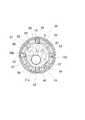
図2に挿入部2の先端部分を示し、また図3に挿入部2における先端硬質部2cの先端面の構成を示す。これらの図から明らかなように、先端硬質部2cにはその軸線の延長線方向、つまり先端硬質部2cの前方を視野とし、所定の視野角Vを有する内視鏡観察手段と、この内視鏡観察手段の視野より基端側の位置で円形若しくは円弧状の超音波走査面Wを有する電子ラジアル走査式の超音波観測手段とが設けられている。 FIG. 2 shows the distal end portion of the
図4に挿入部2の先端部分の断面を示す。この図と図3とから明らかなように、内視鏡観察手段は、照明部10と観察部11とから構成され、照明部10は観察部11を挟んだ両側の位置に配設されている。照明部10は先端硬質部2cの先端面に臨む照明用レンズ10aと、ライトガイド10b(図5〜図8参照)とからなり、ライトガイド10bは、光学繊維束からなり、ユニバーサルコード3の接続コネクタ3aから挿入部2の先端硬質部2cにまで延在されて、その照明光出射端が照明用レンズ10aと対面する位置に臨んでいる。一方、観察部11は対物レンズ11aと、この対物レンズ11aからの光路を90°を曲げるプリズム11bとからなり、対物レンズ11aは鏡筒12内に設けられ、プリズム11bは鏡筒12に固着して設けられる。そして、プリズム11bには固体撮像素子13が接合されており、固体撮像素子13の基板13aには信号線が所定数接続されている。この信号線は束ねられて1本の映像信号ケーブル14としてユニバーサルコード3の接続コネクタ3bにまで延在されている。 FIG. 4 shows a cross section of the distal end portion of the
挿入部2の先端硬質部2cにおける先端面には、さらに鉗子その他の処置具を導出するための処置具導出用開口15が設けられており、この処置具導出用開口15には本体操作部1に設けた処置具導入部5からの処置具挿通チューブが接続される接続パイプ16が装着されている。また、処置具挿通チューブは本体操作部1の内部で吸引通路と合流させるように構成する。さらに、先端硬質部2cには観察部11における対物レンズ11aの先端面が体液等で汚損されたときに、洗浄するためのノズル17が装着されている。そして、このノズル17には送気送水ボタン6により操作される洗浄用流体供給チューブ9が接続されている。 The distal end surface of the distal end
内視鏡観察手段は以上のように構成されるが、これら内視鏡観察手段を構成する各部材の先端部分は、内視鏡装着部材18に固定的に保持されるようになっている。内視鏡装着部材18は、前述した内視鏡観察手段を構成する各部材を挿通させる透孔を複数形成したステンレス等の金属材からなり、この内視鏡装着部材18には先端キャップ19が嵌合されており、この先端キャップ19によって、金属材から構成される内視鏡装着部材18が外部に露出しないようになし、これら内視鏡装着部材18と先端キャップ19とで先端ブロックが構成される。そして、先端キャップ19には、図5に示したように、その厚み方向に向けて2箇所のねじ孔19aが形成されており、これらのねじ孔19aに止めねじ20が螺挿されて、この止めねじ20の先端を内視鏡装着部材18に圧接させると共に内視鏡装着部材18と先端キャップ19との当接面を接着することによって、内視鏡装着部材18と先端キャップ19とからなる先端ブロックが一体化されている。 The endoscope observation means is configured as described above, but the distal end portion of each member constituting the endoscope observation means is fixedly held by the
先端硬質部2cにおける先端キャップ19の基端側位置にラジアル方向の走査面を有する超音波観測手段が装着されている。この超音波観測手段は、図6から明らかなように、多数の超音波振動子21を円周方向に配列したものからなり、超音波振動子21は円周状若しくは円弧状(例えば270°程度)に配列されて、電子走査を行なうように構成したものである。このように配列した超音波振動子21の内周側にはバッキング材22が、また外周側には音響レンズ23が装着されており、これら多数の超音波振動子21とバッキング材22及び音響レンズ23により超音波送受信ユニット24が構成される。 Ultrasonic observation means having a radial scanning surface is attached to the proximal end side position of the
各超音波振動子21はそれぞれ2個の電極25,26を有するものであり、一方の電極25は全ての(若しくは所定数毎の)超音波振動子21に共通の共通電極25であり、また他方の電極26は各超音波振動子21に個別のものである。そして、これら超音波振動子21の共通電極25及び個別電極26は、それぞれフィルム基板に形成した配線パターンの端子部と電気的に接続されることになる。そして、図7に示したように、所定数からなるケーブル27を個別電極26とそれぞれ電気的に接続するために、各超音波振動子21の個別電極26とケーブル27との間にはフィルム基板28が接続されるようになっている。一方、共通電極25とケーブルとの接続は原理的には1本で良いものであり、図示は省略するが、このケーブルの接続は超音波振動子21の先端側で行なうようにしている。そして、バッキング材22の基端側には小径部22aが形成されており、フィルム基板28はこの小径部22aにまで延在されて、各超音波振動子21の個別電極26とケーブル27とがこの小径部22aの位置で接続されるようになっている。これら超音波信号用のケーブル27(共通電極用のケーブルを含む)は、ユニバーサルコード3に設けた接続コネクタ3cにまで延在されて、超音波観測装置に接続されることになる。 Each
以上のように、超音波送受信ユニット24は概略円筒形状となっており、その内周面がトンネル状通路となっており、前述した内視鏡観察手段を構成する各部材はこの超音波送受信ユニット24によるトンネル状通路の内部に挿通されている。そして、超音波送受信ユニット24の基端側は連結部材30と当接しており、この連結部材30は先端硬質部2cにおけるアングル部2bへの連結部を構成する。さらに、この連結部材30の内側には架橋部材31が設けられており、従ってアングル部2bの構造体を構成するアングルリングにおける最先端リング32が連結部材30と架橋部材31とに連結されるようになっている。即ち、図8から明らかなように、連結部材30と架橋部材31との間は複数のねじ33により連結されており、また最先端リング32は複数のねじ34により連結されている。 As described above, the ultrasonic transmission /
そして、この図8に示した先端硬質部2cとアングル部2bとの連結部には、挿入部2内に引き回される各種の部材が挿通されるようになっており、2本に束ねられたライトガイド10b,映像信号ケーブル14と、4本程度に束ねられた超音波信号用のケーブル27が挿通されており、これらは断面形状が任意となる。また、処置具挿通路を構成する接続パイプ16及び洗浄用流体供給チューブ9と、後述するバルーン41内への超音波伝達媒体を供給するためのチューブ43がそれらである。 Then, various members drawn into the
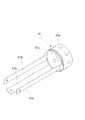
ここで、架橋部材31は、先端硬質部2cの最も基端側に配置されている連結部材30と共にアングル部2bの最先端位置を構成する先端リング32とを連結する機能と、超音波送受信ユニット24を先端硬質部2cの軸線と直交する方向における位置規制を行なう機能と、内視鏡装着部18と先端キャップ19との結合体に対する連結機能とを発揮させるためのものである。従って、この架橋部材31は高い強度を備える必要があり、また外部に露出しない部材であるから、ステンレス等の金属で形成される。そして、図9に示したように、ねじ33及び34により連結部材30及びアングル部2bの最先端リング32に連結される部位は筒状部31aとなっており、この筒状部31aには複数本(本実施の形態においては3本)の連結アーム31bが先端側に向けて延在されている。 Here, the bridging
従って、超音波送受信ユニット24をこれら連結アーム31bに嵌合させることによって、その軸線と直交する方向の位置決めがなされ、また各連結アーム31bの先端部と内視鏡装着部材18との間をねじ35で連結することによって、先端硬質部2cの全体がアセンブルされた状態で固定されることになる。さらに、架橋部材31の筒状部31aの外周面には段差31cが形成されており、この段差31cより基端側が大径になっている。また、連結部材30の内周面にも段差30aが形成されて、この段差30aより基端側の内周面の直径が大きくなっている。この段差30a,31cを接合させることにより超音波送受信ユニット24が先端キャップ19と連結部材30との間に挟持されるようになっている。そして、これら超音波送受信ユニット24の両端面と先端キャップ19の基端面及び連結部材30の先端面とを接着することによって、超音波送受信ユニット24の軸線方向の位置決め及び回転止めがなされ、もって超音波送受信ユニット24は所定位置に固定的に保持されることになる。さらにまた、アングル部2bの外皮層36は連結部材30の基端側の外周面部にまで延在されており、この外皮層36の先端部は糸巻き及び接着剤からなる固着機構37によって、先端硬質部2cの連結部材30に固着されている。 Therefore, by fitting the ultrasonic transmission /
ここで、超音波送受信ユニット24を構成する各超音波振動子21からは体内に向けて超音波を送信し、体内における組織断層部からの反射エコーを受信するが、このように送受信される超音波の減衰を抑制するために、超音波送受信ユニット24の装着部を挟んだ前後の位置、つまり先端キャップ19と連結部材30との外周面には円環状凹溝40,40が設けられており、これら両円環状凹溝40,40間には、図2から明らかなように、超音波伝達媒体が封入されることにより膨出するバルーン41が装着されるようになっている。このバルーン41は筒状をした可撓膜41aからなり、この可撓膜41aの両端には円環状凹溝40に止着される止着リング41bが設けられており、これら止着リング41bは円環状凹溝40に対して締め付け力が作用するようにして止着される。そして、連結部材30には、バルーン41の内部に超音波伝達媒体の給排を行なうための給排通路42が穿設されており、この給排通路42にはチューブ43が接続されている。 Here, each
このように構成することによって、挿入部2を被験者の体腔内に挿入して、内視鏡観察手段を構成する照明部10から体腔内に照明光を照射して、観察部11に装着した対物レンズ11aによって、体腔内の像を固体撮像素子13に結像させて、この固体撮像素子13により体腔内の映像信号を取得して、映像信号処理装置に伝送し、この映像信号処理装置において、所定の信号処理を行なうことによって、内視鏡映像表示用のモニタに体腔内の映像が表示される。従って、このモニタを目視することによって、体腔内の状態に関する内視鏡検査を行なうことができる。 By configuring in this way, the
そして、この内視鏡検査の結果、病変部等といった関心領域があると、超音波観測手段を構成する超音波送受信ユニット24をこの関心領域と対面する位置に移動させる。つまり、挿入部2を所定距離だけ前進させることによって、超音波送受信ユニット24が関心領域に対面する位置に配置される。そして、バルーン41内に超音波伝達媒体を供給して、その可撓膜41aを膨出させて、体腔内壁に密着させる。この状態で、超音波送受信ユニット24を構成する円周方向に配列した超音波振動子21を順次作動させて、体内に向けて超音波パルスを送信して、その反射エコーを受信する。ここで、超音波振動子21は順次1個ずつ作動させることもできるが、複数個の超音波振動子21を所定の時間遅れを持たせて作動させることによって、例えば電子フォーカスをかけることができる。なお、多数配列した超音波振動子21を電子走査する方式については、従来から周知であるので、ここではその説明を省略する。 If there is a region of interest such as a lesion as a result of this endoscopy, the ultrasonic transmission /
以上のようにして、超音波送受信ユニット24を構成する各超音波振動子21により取得した反射エコー信号を超音波観測装置に伝送して、この超音波観測装置で信号処理を行なうことによって、関心領域を含む体内組織の状態に関する断層情報が取得される。そして、この超音波断層像は超音波観測装置に付設したモニタに表示されることになる。これによって、組織内に病変部が含まれるか否か等といった診断が可能になる。 As described above, the reflected echo signals acquired by the respective
先端硬質部2cは、内視鏡観察手段を構成する各部材が内周側に、超音波観測手段を構成する各部材は外周側にそれぞれ配置される。そして、内視鏡観察手段を構成する各部材は、超音波送受信ユニット24により形成されるトンネル状通路を挿通させて、この超音波送受信ユニット24の前方位置に装着した内視鏡装着部材18及び先端キャップ19まで延在されている。そして、先端キャップ19は、超音波送受信ユニット25の外径とほぼ同じ外径寸法としている。従って、超音波送受信ユニット25より前方側には、そのトンネル状通路の寸法に規制されないスペースが確保される。 In the distal end
そこで、照明部10の先端部分の断面構成を図10に示す。この照明部10は、既に説明したように、照明用レンズ10aとライトガイド10bとから構成されるが、ライトガイド10bは光学繊維束からなり、それ自体は曲げ可能であり、かつ断面形状も変形可能となっている。そして、このライトガイド10bの出射端側における所定の長さ分は口金10cに挿入されて、接着剤を用いて固着されている。一方、照明用レンズ10aは、ライトガイド10bからの照明光をロスなく効率的に出射させるために、ライトガイド10bの外径寸法より大きい直径とする。そして、ライトガイド10bは口金10cに挿通されている部位は内視鏡装着部18に形成した透孔18aに挿通されており、照明用レンズ10aは先端キャップ19に形成した透孔19aに装着されている。さらに、ライトガイド10bの口金10cへの挿通部より基端側は変形自在となっている。 Therefore, FIG. 10 shows a cross-sectional configuration of the tip portion of the
以上のことから、照明部10を構成する部材のうち、最も細径であり、しかも曲げ及び変形自在な部位が超音波送受信ユニット24の内部のトンネル状通路という最も狭窄な通路内に挿通されているので、照明部10はトンネル状通路を容易に通過させることができる。また、照明部10のうち、最も大径の部材である照明用レンズ10aはトンネル状通路の前方であって、外径の大きい先端キャップ19に装着されているので、他の部材と干渉するおそれはない。 From the above, among the members constituting the illuminating
また、観察部11を構成する固体撮像素子13及びその基板13aは超音波送受信ユニット24により形成されるトンネル状通路の内部に位置している。基板13aは広い面積を有する板状の部材であるから、その板面が先端硬質部の軸線方向に向くように配設するようになし、かつトンネル状通路の中心近傍の位置に配設している。一方、対物レンズ11a及びその鏡筒12は先端硬質部2cの周縁部に近い位置に配置する。これによって、対物レンズ11a及びその鏡筒12と、固体撮像素子13及びその基板13aというように、異形の部材を連結した観察部11において、固体撮像素子13から斜め前方に向けて傾斜するプリズム11bの背面に超音波送受信ユニット24におけるトンネル状通路を形成するバッキング材22の内周先端部を配置させている。従って、このように異形の部材の連結構造となった観察部11を、狭窄な通路であるトンネル状通路内において、格別のデッドスペースを作ることなく容易に配置でき、かつトンネル状通路の前方位置で外周側に大きく突出させるようにしているので、超音波送受信ユニット24と干渉しないように設置することができる。 In addition, the solid-
以上のように、照明部10及び観察部11を構成する一部の部材をトンネル状通路の内径より外周側に向けて部分的にはみ出すように装着することによって、先端硬質部2cを太径化することなく、全ての部材を合理的に装着できるようになり、挿入部2の細径化が図られる。また、概略円環状部材である超音波送受信ユニット24を先端硬質部2cにおいて、その軸線と直交する方向の位置決めを行なうために、そのトンネル状通路の内部に架橋部材31を挿通させているが、この架橋部材31は超音波送受信ユニット24の内側においては、3本の狭い幅を有する連結アーム31bで構成されており、処置具挿通路を構成する接続パイプ16や鏡筒12が挿通されている部位、さらにライトガイド10bが挿通されている部位等を避けるようにしているので、この連結アーム31bはトンネル状通路内を挿通させた内視鏡観察手段を構成する各部材に対する障害とはならない。 As described above, by attaching a part of the members constituting the
要するに、図3に示したように、先端硬質部2cの最も太径の部位の半径をR1としたときに、この最大半径R1内において、内視鏡観察手段を構成する全ての部材は半径R2内に位置しており、この内視鏡観察手段の装着領域の半径R2は超音波観測手段が配置されていない先端ブロックの位置である。一方、超音波観測手段における内視鏡観察手段を収容するトンネル状通路の内径はR3であるが、この半径R3の位置は内視鏡装着領域が最大半径R2となる位置より基端側であって、R3<R2となっている。従って、その間でオーバーラップしている領域Sの寸法分だけ先端硬質部2cの半径R1を細径化することができる。 In short, as shown in FIG. 3, when the radius of the thickest part of the distal end
1 本体操作部 2 挿入部
2a 軟性部 2b アングル部
2c 先端硬質部 10 照明部
10a 照明用レンズ 10b ライトガイド
11 観察部 11a 対物レンズ
11b プリズム 12 鏡筒
13 固体撮像素子 13a 基板
18 内視鏡装着部材 19 先端キャップ
21 超音波振動子 22 バッキング材
23 音響レンズ 24 超音波送受信ユニット
30 連結部材 31 架橋部材
31a 筒状部 31b 連結アーム
DESCRIPTION OF SYMBOLS 1 Main
Claims (4)
Translated fromJapanese前記超音波観測手段は、その内周面がバッキング層となり、概略円筒形状のトンネル状通路を有する超音波送受信ユニットを備え、
この超音波送受信ユニットの配設部より前記先端硬質部の軸線方向の前方側に先端ブロックを配設させて、この先端ブロックに前記内視鏡観察手段を構成する各部材の先端部を固定し、
前記内視鏡観察手段を構成する一部の部材は、前記先端ブロックにおいて、前記トンネル状通路の内径より外周側に向けて部分的にはみ出すように装着する
構成としたことを特徴とする超音波内視鏡。Endoscopic observation means with an observation field at the front of the distal end hard portion of the insertion portion, and a predetermined number of ultrasonic transducers arranged in the circumferential direction on the outer peripheral portion of the distal end hard portion, are circumferential or arcuate In an ultrasonic endoscope equipped with an ultrasonic observation means having a scanning range of
The ultrasonic observation means includes an ultrasonic transmission / reception unit having an inner circumferential surface serving as a backing layer and having a substantially cylindrical tunnel-shaped passage,
A distal end block is disposed on the front side in the axial direction of the distal end rigid portion from the disposed portion of the ultrasonic transmission / reception unit, and the distal end portion of each member constituting the endoscope observation means is fixed to the distal end block. ,
The ultrasonic wave characterized in that a part of the members constituting the endoscope observation means is mounted on the tip block so as to partially protrude from the inner diameter of the tunnel-shaped passage toward the outer peripheral side. Endoscope.
The distal end block is fitted with an endoscope mounting member formed of a metal material so that the members constituting the endoscope observation means are not exposed to the outside. A tip cap is formed, and at least at the position of the tip cap, the diameter of the illuminating unit or the observation unit is increased so as to partially protrude from the inner diameter of the tunnel-shaped passage. Item 2. The ultrasonic endoscope according to Item 2.
Priority Applications (6)
| Application Number | Priority Date | Filing Date | Title |
|---|---|---|---|
| JP2004199344AJP4618410B2 (en) | 2004-07-06 | 2004-07-06 | Ultrasound endoscope |
| AT05014456TATE372722T1 (en) | 2004-07-06 | 2005-07-04 | ULTRASONIC ENDOSCOPE |
| DE602005002405TDE602005002405T2 (en) | 2004-07-06 | 2005-07-04 | An ultrasonic endoscope |
| EP05014456AEP1614390B1 (en) | 2004-07-06 | 2005-07-04 | Ultrasonic endoscope |
| US11/172,849US7569012B2 (en) | 2004-07-06 | 2005-07-05 | Ultrasonic endoscope |
| CNB2005100822897ACN100387200C (en) | 2004-07-06 | 2005-07-06 | Ultrasonic endoscope |
Applications Claiming Priority (1)
| Application Number | Priority Date | Filing Date | Title |
|---|---|---|---|
| JP2004199344AJP4618410B2 (en) | 2004-07-06 | 2004-07-06 | Ultrasound endoscope |
Publications (2)
| Publication Number | Publication Date |
|---|---|
| JP2006020703Atrue JP2006020703A (en) | 2006-01-26 |
| JP4618410B2 JP4618410B2 (en) | 2011-01-26 |
Family
ID=35794402
Family Applications (1)
| Application Number | Title | Priority Date | Filing Date |
|---|---|---|---|
| JP2004199344AExpired - LifetimeJP4618410B2 (en) | 2004-07-06 | 2004-07-06 | Ultrasound endoscope |
Country Status (2)
| Country | Link |
|---|---|
| JP (1) | JP4618410B2 (en) |
| CN (1) | CN100387200C (en) |
Cited By (1)
| Publication number | Priority date | Publication date | Assignee | Title |
|---|---|---|---|---|
| CN113616302A (en)* | 2021-09-10 | 2021-11-09 | 希罗镜下医疗科技发展(上海)有限公司 | Grabber used under endoscope |
Families Citing this family (24)
| Publication number | Priority date | Publication date | Assignee | Title |
|---|---|---|---|---|
| US20060282097A1 (en) | 2005-06-13 | 2006-12-14 | Ortiz Mark S | Surgical suturing apparatus with a non-visible spectrum sensing member |
| JP2007236414A (en)* | 2006-03-03 | 2007-09-20 | Olympus Medical Systems Corp | Ultrasound endoscope |
| US20080051626A1 (en)* | 2006-08-28 | 2008-02-28 | Olympus Medical Systems Corp. | Fistulectomy method between first duct and second duct, ultrasonic endoscope, catheter with balloon, magnet retaining device, and magnet set |
| CN101703415B (en)* | 2008-10-10 | 2011-04-06 | 广州宝胆医疗器械科技有限公司 | Hard ultrasonic gallbladder endoscope system |
| CN101366649B (en)* | 2008-10-10 | 2010-06-09 | 乔铁 | Bile-preserving series endoscopy system |
| CN102028507A (en)* | 2010-12-30 | 2011-04-27 | 广州宝胆医疗器械科技有限公司 | Integrated color Doppler ultrasonic hysteroscope system |
| CN102008323A (en)* | 2010-12-30 | 2011-04-13 | 广州宝胆医疗器械科技有限公司 | Electronic oviduct lens system having color Doppler ultrasound scanning function |
| CN102068284B (en)* | 2010-12-30 | 2012-07-25 | 广州宝胆医疗器械科技有限公司 | Hard enteroscope system with color Doppler ultrasonic scanning function |
| CN102008322B (en)* | 2010-12-30 | 2012-07-25 | 广州宝胆医疗器械科技有限公司 | Cholecystoscope system with color Doppler ultrasonic scanning function |
| CN102018534B (en)* | 2010-12-30 | 2012-05-23 | 广州宝胆医疗器械科技有限公司 | Integrated color Doppler ultrasound electronic bronchoscope system |
| CN102028505A (en)* | 2010-12-30 | 2011-04-27 | 广州宝胆医疗器械科技有限公司 | Integrated color Doppler ultrasonic cystoscope system |
| CN102028502B (en)* | 2010-12-30 | 2012-07-25 | 广州宝胆医疗器械科技有限公司 | Electronic laryngoscope system with color Doppler ultrasound scanning function |
| CN102018535A (en)* | 2010-12-30 | 2011-04-20 | 广州宝胆医疗器械科技有限公司 | Integrated color doppler ultrasound electronic laryngoscope system |
| CN102068285B (en)* | 2010-12-30 | 2012-09-26 | 广州宝胆医疗器械科技有限公司 | Esophagoscope system with color Doppler ultrasound scanning function |
| CN102068286A (en)* | 2010-12-30 | 2011-05-25 | 广州宝胆医疗器械科技有限公司 | Integrated color Doppler ultrasound electronic falloposcope system |
| CN102028503B (en)* | 2010-12-30 | 2012-07-25 | 广州宝胆医疗器械科技有限公司 | Hysteroscope system with color Doppler ultrasonic scanning function |
| CN102028506A (en)* | 2010-12-30 | 2011-04-27 | 广州宝胆医疗器械科技有限公司 | Integrated color Doppler ultrasound esophagoscope system |
| JP5830328B2 (en)* | 2011-09-26 | 2015-12-09 | オリンパス株式会社 | Endoscope image processing apparatus, endoscope apparatus, and image processing method |
| CN103648404B (en)* | 2012-07-04 | 2015-06-17 | 奥林巴斯医疗株式会社 | Ultrasonic endoscope |
| CN103860130A (en)* | 2012-12-13 | 2014-06-18 | 蒋小华 | Novel ultrasonic probe gastroscope exploring tube |
| JP5953441B2 (en)* | 2014-06-10 | 2016-07-20 | オリンパス株式会社 | Biopsy system |
| DE112016006633T5 (en)* | 2016-03-23 | 2018-12-06 | Olympus Corporation | endoscope |
| WO2018051565A1 (en)* | 2016-09-15 | 2018-03-22 | オリンパス株式会社 | Ultrasonic endoscope and ultrasonic endoscope system |
| WO2020044905A1 (en)* | 2018-08-27 | 2020-03-05 | 富士フイルム株式会社 | Ultrasound endoscope balloon, ultrasound endoscope equipped with same, and production method therefor |
Citations (4)
| Publication number | Priority date | Publication date | Assignee | Title |
|---|---|---|---|---|
| JPS63135143A (en)* | 1986-11-28 | 1988-06-07 | オリンパス光学工業株式会社 | Ultrasonic endoscope |
| JPH11276424A (en)* | 1998-03-30 | 1999-10-12 | Fuji Photo Optical Co Ltd | Tip structure of insert part of strabismus endoscope |
| JP2001314403A (en)* | 2000-05-10 | 2001-11-13 | Asahi Optical Co Ltd | Radial scanning forward-looking ultrasonic endoscope |
| JP2004159837A (en)* | 2002-11-12 | 2004-06-10 | Pentax Corp | Tip of radial scanning ultrasonic endoscope |
Family Cites Families (4)
| Publication number | Priority date | Publication date | Assignee | Title |
|---|---|---|---|---|
| JP3379406B2 (en)* | 1997-09-24 | 2003-02-24 | 富士写真光機株式会社 | Ultrasound probe inserted endoscopically |
| US6511431B2 (en)* | 2000-05-10 | 2003-01-28 | Pentax Corporation | Radial scan, forward viewing ultrasonic endoscope |
| JP3579646B2 (en)* | 2000-11-21 | 2004-10-20 | ペンタックス株式会社 | Ultrasound endoscope |
| EP1414347A1 (en)* | 2001-07-31 | 2004-05-06 | Koninklijke Philips Electronics N.V. | Transesophageal and transnasal, transesophageal ultrasound imaging systems |
- 2004
- 2004-07-06JPJP2004199344Apatent/JP4618410B2/ennot_activeExpired - Lifetime
- 2005
- 2005-07-06CNCNB2005100822897Apatent/CN100387200C/ennot_activeExpired - Fee Related
Patent Citations (4)
| Publication number | Priority date | Publication date | Assignee | Title |
|---|---|---|---|---|
| JPS63135143A (en)* | 1986-11-28 | 1988-06-07 | オリンパス光学工業株式会社 | Ultrasonic endoscope |
| JPH11276424A (en)* | 1998-03-30 | 1999-10-12 | Fuji Photo Optical Co Ltd | Tip structure of insert part of strabismus endoscope |
| JP2001314403A (en)* | 2000-05-10 | 2001-11-13 | Asahi Optical Co Ltd | Radial scanning forward-looking ultrasonic endoscope |
| JP2004159837A (en)* | 2002-11-12 | 2004-06-10 | Pentax Corp | Tip of radial scanning ultrasonic endoscope |
Cited By (1)
| Publication number | Priority date | Publication date | Assignee | Title |
|---|---|---|---|---|
| CN113616302A (en)* | 2021-09-10 | 2021-11-09 | 希罗镜下医疗科技发展(上海)有限公司 | Grabber used under endoscope |
Also Published As
| Publication number | Publication date |
|---|---|
| CN1718165A (en) | 2006-01-11 |
| JP4618410B2 (en) | 2011-01-26 |
| CN100387200C (en) | 2008-05-14 |
Similar Documents
| Publication | Publication Date | Title |
|---|---|---|
| JP4618410B2 (en) | Ultrasound endoscope | |
| EP1614390B1 (en) | Ultrasonic endoscope | |
| US6461304B1 (en) | Ultrasound inspection apparatus detachably connected to endoscope | |
| US7488288B2 (en) | Ultrasonic endoscope | |
| US20200107708A1 (en) | Endoscope | |
| JP4484044B2 (en) | Ultrasound endoscope | |
| US11684340B2 (en) | Ultrasound endoscope | |
| EP1707125B1 (en) | Ultrasonic endoscope | |
| US20200037989A1 (en) | Ultrasound endoscope | |
| US20180098688A1 (en) | Lens unit and endoscope | |
| JP2018134276A (en) | Treatment instrument channel and endoscope | |
| WO2021161497A1 (en) | Ultrasonic endoscope | |
| WO2017010292A1 (en) | Ultrasonic transducer module and ultrasonic endoscope | |
| JP2023128309A (en) | Endoscope | |
| JP4248909B2 (en) | Ultrasound endoscope | |
| JP4488203B2 (en) | Ultrasound endoscope | |
| JP2017074231A (en) | Method of manufacturing ultrasonic endoscope and ultrasonic endoscope | |
| US11944496B2 (en) | Ultrasound endoscope | |
| JP4535252B2 (en) | Ultrasound endoscope | |
| JP2001112757A (en) | In-coelom diagnostic apparatus | |
| JP2023128308A (en) | Endoscope | |
| US10244924B2 (en) | Endoscope | |
| JP2024047233A (en) | Ultrasound endoscope | |
| JP2006158481A (en) | Ultrasonic endoscope | |
| JP2001095796A (en) | Separation possible ultrasonic endoscope |
Legal Events
| Date | Code | Title | Description |
|---|---|---|---|
| A621 | Written request for application examination | Free format text:JAPANESE INTERMEDIATE CODE: A621 Effective date:20070423 | |
| A711 | Notification of change in applicant | Free format text:JAPANESE INTERMEDIATE CODE: A711 Effective date:20090916 | |
| A977 | Report on retrieval | Free format text:JAPANESE INTERMEDIATE CODE: A971007 Effective date:20100226 | |
| A131 | Notification of reasons for refusal | Free format text:JAPANESE INTERMEDIATE CODE: A131 Effective date:20100303 | |
| A521 | Request for written amendment filed | Free format text:JAPANESE INTERMEDIATE CODE: A523 Effective date:20100430 | |
| TRDD | Decision of grant or rejection written | ||
| A01 | Written decision to grant a patent or to grant a registration (utility model) | Free format text:JAPANESE INTERMEDIATE CODE: A01 Effective date:20100929 | |
| A01 | Written decision to grant a patent or to grant a registration (utility model) | Free format text:JAPANESE INTERMEDIATE CODE: A01 | |
| A61 | First payment of annual fees (during grant procedure) | Free format text:JAPANESE INTERMEDIATE CODE: A61 Effective date:20101012 | |
| FPAY | Renewal fee payment (event date is renewal date of database) | Free format text:PAYMENT UNTIL: 20131105 Year of fee payment:3 | |
| R150 | Certificate of patent or registration of utility model | Ref document number:4618410 Country of ref document:JP Free format text:JAPANESE INTERMEDIATE CODE: R150 | |
| R250 | Receipt of annual fees | Free format text:JAPANESE INTERMEDIATE CODE: R250 | |
| R250 | Receipt of annual fees | Free format text:JAPANESE INTERMEDIATE CODE: R250 | |
| R250 | Receipt of annual fees | Free format text:JAPANESE INTERMEDIATE CODE: R250 | |
| R250 | Receipt of annual fees | Free format text:JAPANESE INTERMEDIATE CODE: R250 | |
| R250 | Receipt of annual fees | Free format text:JAPANESE INTERMEDIATE CODE: R250 | |
| R250 | Receipt of annual fees | Free format text:JAPANESE INTERMEDIATE CODE: R250 | |
| R250 | Receipt of annual fees | Free format text:JAPANESE INTERMEDIATE CODE: R250 | |
| R250 | Receipt of annual fees | Free format text:JAPANESE INTERMEDIATE CODE: R250 | |
| R250 | Receipt of annual fees | Free format text:JAPANESE INTERMEDIATE CODE: R250 | |
| R250 | Receipt of annual fees | Free format text:JAPANESE INTERMEDIATE CODE: R250 | |
| R250 | Receipt of annual fees | Free format text:JAPANESE INTERMEDIATE CODE: R250 | |
| EXPY | Cancellation because of completion of term |